Embed Size (px)
Citation preview
MTLDKGB REV.112006
AIR COOLED WATER CHILLERS, CONDENSING UNITS AND HEAT PUMPS WITH AXIAL FANS
LDK SERIES
TECHNICAL MANUAL
LDK Air cooled water chillers
MTLDKGB REV.112006 2
LDK Air cooled water chillers
MTLDKGB REV.112006 5
INDEX
Declaration of conformity page 2 Aim and contents of this manual page 6 How to keep this manual page 6 Graphic symbols page 6 Safety laws page 7 General safety guidelines page 7 Workers’ health and safety page 8
Protective equipment page 8 Safety signs page 8 Technical characteristics page 9 Technical data page 12 LDK cooling capacity and compressors input power page 19 LDK/HP heating capacity and compressors input power page 24 LDK/CN/LS cooling capacity and compressors input power page 28 Evaporator pressure drops page 31 Water pumps available static pressure page 32 Free Cooling Capacity page 33 Partial heat recovery capacity page 34 Operation limits page 35 Compressors capacity step controls page 36 Corrections tables page 36 Sound Data page 37 Safety Device Setting page 38 Electric data page 38 Inspection page 38 Lifting and handling page 38 Location and minimum technical clearances page 39 Hydraulic connections page 40 LDK / CN refrigerant connections page 42 LDK/FC Free cooling version page 43 Remote control panel page 44 Fan speed control page 45 Electrical connections page 45 Start up page 45 Maintenance and periodic checks page 46 Refrigerant circuit repair page 47 Environment protection page 47 Unit out of service page 47 Fault finding page 47 Dimensions page 48
LDK Air cooled water chillers
MTLDKGB REV.112006 7
SAFETY LAWS HIDROS SRL’s equipment and their component parts have been designed in compliance with the harmonised EC norms in force and other European and national norms as required by the Council Directive (98/37 and later amendments). The equipment i salso compliant with: • Norms EN 292-1 e 292-2 • Norma EN 294 • Norms EN 378-1, 378-2, 378-3 e 378-4 • Norma EN 418 • Norma EN 953 • Norma EN 1050 • Norma EN 60204-1 • Norma EN 61000-6-2 • Norma EN 61000-6-4 • Community Directives 98/37/CE, 97/23/CE, 93/68/CEE, 89/336/CEE 73/23/CEE GENERAL SAFETY GUIDELINES Before beginning to operate on LDK units every user must be perfectly knowledgeable about the functions of the equipment and its controls and must have read and understood the information container in this manual.
It’s strictly forbidden to remove and/or camper with any safety device.
Any routine or not-routine maintenance operation shall be carried out when the equipment has been shut down, disconnected from electric and pneumatic power source and after its pneumatic system has been discharged.
Do not put your hands or insert screwdrivers, spanners or other tools into moving parts of the equipment.
The equipment supervisor and the maintenance man must receive training suitable for the performance of their tasks in safety
Operators must know how to use personal protective devices and must know the accident-prevention guidelines contained in national and international laws and norms.
LDK Air cooled water chillers
MTLDKGB REV.112006 8
WORKERS’ HEALTH AND SAFETY The European Community has adopted a number of directives on workplace health and safety, which include directives 89/391/CEE, 89/686/CEE, 89/655/CEE, 86/188/CEE and 77/576/CEE. Every employer shall implement such provisions and ensure that workers respect them:
Do not tamper with or replace parts of the equipment without the specific consent of the manufacturer. The manufacturer shall have no responsibility whatsoever in case of unauthorised operations.
Using components, expendable materials or spare parts that do not correspond to those recommended by the manufacturer and/or listed in this manual may be dangerous for the operators and/or damage the equipment
The operator’s workplace must be kept clean, tidy and free from objects that may camper free movements. Appropriate lighting of the work place shall be provided so as to allow the operator to carry out the required operations safely. Poor or too strong lighting can cause risks.
Ensure that work places are always adequately ventilated and that aspirators are working, in good condition and in compliance with the requirements of the laws in force..
PROTECTIVE EQUIPMENT Nelle operazioni di utilizzo e manutenzione delle unità UTH è necessario prevedere l’uso di mezzi personali di protezione quali: When operating and maintaining the UTH unit, use the following personal protective equipment.
Protective clothing: Maintenance men and operators must wear protective clothing that complies with the basic safety requirements currently in force. In case of slippery floors users must wear safety shoes with non-slip soles.
Gloves: During maintenance or cleaning operation protection gloves must be used
Mask and googles: Respiratory protection (mask) and eye protection (goggles) should be used during cleaning and maintenance operations.
SAFETY SIGNS The equipment features the following safety signs, which must be complied with:
General hazard
Electric shock hazard
LDK Air cooled water chillers
MTLDKGB REV.112006 9
TECHNICAL CHARACTERISTICS
Frame All LDK units are made from hot-galvanised thick sheet metal, painted with polyurethane powder enamel at 180°C to ensure the best resistance against the atmospheric agents. The frame is self-supporting with removable panels. All screws and rivets for outdoor installations are in stainless steel. The colour of the units is RAL 7035. Refrigerant circuit The refrigerant gas used in these units is R407C. The refrigerant circuit is made by using international primary brands components and according to ISO 97/23 concerning welding procedures. Each refrigerant circuit is totally independent from the other. Any incorrect operation of one circuit does not influence the other circuit. The refrigerant circuit includes: liquid line manual shut-off valve, sight glass, filter drier, thermal expansion valve with external equalizer, electric expansion valve with electronic control to optimize the efficiency in part load conditions (option), reverse cycle valve (for heat pump version only), one way valve (for heat pump version only), liquid receiver (for heat pump version only), Schrader valves form maintenance and control, pressure safety device (according to PED regulation). Compressors The compressors are scroll type, with crankcase heater and thermal overload protection by a klixon embedded in the motor winding. They are mounted in a separate chamber in order to be separated from the air stream. The crankcase heater is always powered when the compressors are in stand-by. The inspection is possible through the frontal panel of the unit that allows the maintenance of the compressors even if the unit is working. The compressors used are all in tandem execution. This solution allows much higher efficiencies in partial loads compared to the units with independent refrigerant circuits. Condensers The condensers are made of copper pipes and aluminium fins. The diameter of the copper pipes is 3/8” and the thickness of the aluminium fins is 0,1 mm. The tubes are mechanically expanded into the aluminium fins to improve the heat exchange factor. The geometry of these condensers guarantees a low air side pressure drop and then the use of low rotation (and low noise emission) fans. The condensers can be protected by a metallic filter to be installed on request. Fans The fans are axial type with aerofoil blades. They are statically and dynamically balanced and supplied complete of the safety fan guard according to EN 60335. They are mounted on the unit frame by interposition of rubber vibration dampers. The electric motors are all at 6 poles (about 900 rpm) in the low noise versions, 8 poles (about 750 rpm) in the extra low noise versions. The motors are directly driven with an integrated thermal overload protection. The protection class of the motors is IP 54. Evaporators The evaporators are made of AISI 316 stainless steel braze-welded plates type. From size 045 to size 130 are single water side circuit, from the size 140 they are double circuit “cross flow” type. The use of these kinds of evaporators allows a massive reduction of the refrigerant charge of the unit compared to the traditional shell-in-tube evaporators and increases the efficiency of the refrigerant cycle in partial loads. The evaporators are factory insulated with flexible close cell material and can be equipped with antifreeze heater (optional). Each evaporator is provided with a temperature sensor as antifreeze protection.
LDK Air cooled water chillers
MTLDKGB REV.112006 10
Electric enclosure The electric switch board is made according to electromagnetic compatibility norms CEE 73/23 and 89/336. The accessibility to the board is possible after removing the front panel of the unit and the OFF positioning of the main switch. The moisture protection degree is IP55. In all LDK units are installed, standard, the compressors sequence relay who disables the operation of the compressor in case the power supply phase sequence is not the correct one (scroll compressors in fact, can be damaged if they rotate reverse wise). The following components are also standard installed: main switch, magnetic-thermal switches (as a protection of pumps and fans), compressors fuses, control circuit automatic breakers, compressor contactors, fan contactors, pump contactors. The terminal board is supplied with voltage free contacts for remote ON-OFF , Summer / winter change over (heat pumps only) and general alarm. Microprocessors All LDK units are supplied standard with microprocessor controls. The microprocessor controls the following functions: regulation of the water temperature, antifreeze protection, compressor timing, compressor automatic starting sequence, alarm reset, potential free contact for remote general alarm, alarms and operation leds. Upon request any microprocessor can be connected to a BMS system for the remote control and management. The technical department is available to study, together with the customer, different solutions using MODBUS; LONWORKS; BACNET or TREND protocols. Control and protection devices All units are supplied with the following control and protection devices: Return water temperature sensor, installed on the return water line from the plant (12°C), antifreeze protection sensor installed on the outlet water temperature (7°C), high pressure switch with manual reset, low pressure switch with automatic reset, high pressure safety valve, compressor thermal overload protection, fans thermal overload protection, flow switch.
LDK Air cooled water chillers
MTLDKGB REV.112006 11
OTHER VERSIONS Unit with integrated hydraulic circuit (A versions) The LDK chillers can be delivered as option, with a built in hydraulic kit that includes: Water tank in different sizes (depending on the size of the unit), factory insulated with flexible close cell material and prepared for the installation of antifreeze kit (option). The water tank is installed to minimize the inevitable fluctuations in the water temperature due to the compressors starts and stops. Water pump, centrifugal type, is available in single or double configuration. In this case one pump is running, one pump is in stand-by. The change over can be manual (by manual selector installed in the electric box) or automatically controlled by the microprocessor (option). In the hydraulic circuit are also present the expansion vessel, the safety valve and the manual valves with fittings. Heat pumps version (HP) The heat pump versions are provided with a 4 way reverse cycle valve and are suitable to produce hot water up to a temperature of 45-50°C. They are always supplied with liquid receiver and a second thermostatic valve to optimize the efficiency of the refrigerant cycle in heating and in cooling. The microprocessor is set for automatic defrost (in case of operation in severe ambient conditions) and for summer/winter change over. Free cooling version (FC) The FREE COOLING option is a system designed to grant an important energy saving, when the cooling system is operating continuously, also during the winter season (computer rooms, telephone exchange plants, etc.).The free-cooling device is using the low ambient air temperature to cool down the water in the system. In some situations the chilled water can be even produced without the work of the compressors with consequent massive reduction of electric power consumption. The FRE COOLING system is composed by the following components: Free cooling coil: It is essentially a heat exchanger made of copper tubes and aluminium fins with bleeding
valves. Microprocessor control: It is the “heart” of the system; it allows the correct control of all the parameters performing the
best efficiency of the system in the different ambient conditions. 3 way valve: It is an ON/OFF 3 way valve that opens or closes the FREE COOLING circuit depending on
the signal coming from the microprocessor control. Head pressure control: It is a device that allows the correct condensing pressure in the refrigerant circuit when the
ambient conditions are low. In the units equipped with FREE COOLING system, this device is composed by solenoid valves that close some refrigerant circuits in the condensing coil in order to reduce its exchange capacity and to keep a suitable condensing pressure level.
Low noise version (LS) The low noise version LS includes the complete insulation of the compressor vane with high density sound absorbtion material. Extra low noise version (XL) The extra low noise version is especially designed to be installed in applications where the sound level is the most important key. The units are built with a special insulation of the compressor box and oversized condensing coils. The units are also equipped with low rpm fan motors (8 poles). Condensing unit version (CN) The condensing unit version is supplied without refrigerant charge (only a nitrogen charge), without evaporator and thermostatic valve. The microprocessor control is present in all units as well as the sight glass, filter drier, liquid line solenoid valve and the refrigerant lines shut off manual valves.
LDK Air cooled water chillers
MTLDKGB REV.112006 12
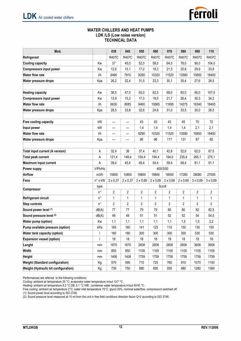
WATER CHILLERS AND HEAT PUMPS
LDK /LS (Low noise version) TECHNICAL DATA
Mod. 039 045 050 060 070 080 090 110
Refrigerant R407C R407C R407C R407C R407C R407C R407C R407C Cooling capacity Kw 37 45,0 52,0 58,0 64,0 78,0 90,0 104,0 Compressors input power Kw 12,6 15,1 17,2 19,3 21,5 25,8 29,9 33,9 Water flow rate l/h 6490 7910 9290 10320 11520 13590 15650 18400 Water pressure drops Kpa 26,2 32,4 31,5 23,3 30,1 30,4 27,6 26,5
Heating capacity Kw 38,5 47,0 55,0 62,0 68,0 83,0 95,0 107,0 Compressors input power Kw 12,9 15,2 17,3 19,5 21,7 26,4 30,3 34,2 Water flow rate l/h 6630 8085 9460 10665 11695 14275 16340 18400 Water pressure drops Kpa 28,5 33,8 32,6 24,8 31,0 33,5 30,0 26,5
Free cooling capacity kW --- --- 43 43 43 45 70 72 Input power kW --- --- 1,4 1,4 1,4 1,4 2,1 2,1 Water flow rate l/h --- --- 9290 10320 11520 13590 15650 18400 Water pressure drops Kpa --- --- 90 96 117 131 87 85
Total input current (A version) A 32,4 36 37,4 40,1 42,8 52,6 62,0 67,5 Total peak current A 121,4 148,4 154,4 194,4 194,0 235,4 265,1 275,1 Maximum input current A 39,4 45,4 49,4 54,4 59,4 69,4 81,1 91,1 Power suppy V/Ph/Hz 400/3/50 Airflow m3/h 10800 10800 18800 18800 18000 17280 28080 27000 Fans n° x kW 2 x 0,37 2 x 0,37 2 x 0,69 2 x 0,69 2 x 0,69 2 x 0,69 3 x 0,69 3 x 0,69
type Scroll Compressor
n° 2 2 2 2 2 2 2 2 Refrigerant circuit n° 1 1 1 1 1 1 1 1 Step controls n° 2 2 2 2 2 2 2 2 Sound power level (1) dB(A) 77 77 79 79 80 80 82 82,5 Sound pressure level (2) dB(A) 49 49 51 51 52 52 54 54,5 Water pump (option) Kw 1,1 1,1 1,1 1,1 1,1 1,5 1,5 2,2 Pump available pressure (option) kPa 165 160 141 125 110 150 130 150 Water tank capacity (option) l 180 180 300 300 300 300 530 530 Expansion vessel (option) l 18 18 18 18 18 18 18 18 Lenght mm 1870 1870 2608 2608 2608 2608 3608 3608 Width mm 850 850 1105 1105 1105 1105 1105 1105 Height mm 1406 1406 1759 1759 1759 1759 1759 1759 Weight (Standard configuration) Kg 570 590 710 725 760 810 1070 1150 Weight (Hydraulic kit configuration) Kg 730 750 880 895 930 980 1280 1360 Performances are referred to the following conditions: Cooling: ambient air temperature 35 °C; evaporator water temperature in/out 12/7 °C. Heating: ambient air temperature 8.3 °C DB, 6.1 °C WB ; condenser water temperature in/out 40/45 °C. Free cooling: ambient air temperature 2°C; water inlet temperature 15°C, glycol 20%, nominal waterflow, compressors switched off. (1): Sound power level according to ISO 3746. (2): Sound pressure level measured at 10 mt from the unit in free field conditions direction factor Q=2 according to ISO 3746.
LDK Air cooled water chillers
MTLDKGB REV.112006 13
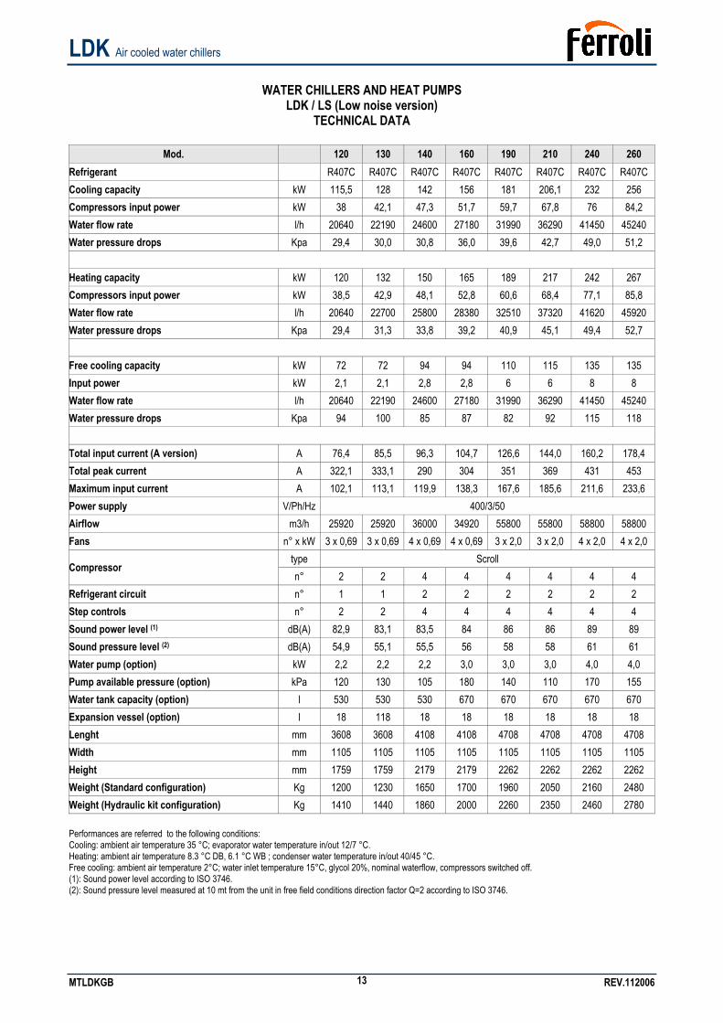
WATER CHILLERS AND HEAT PUMPS
LDK / LS (Low noise version) TECHNICAL DATA
Mod. 120 130 140 160 190 210 240 260
Refrigerant R407C R407C R407C R407C R407C R407C R407C R407C Cooling capacity kW 115,5 128 142 156 181 206,1 232 256 Compressors input power kW 38 42,1 47,3 51,7 59,7 67,8 76 84,2 Water flow rate l/h 20640 22190 24600 27180 31990 36290 41450 45240 Water pressure drops Kpa 29,4 30,0 30,8 36,0 39,6 42,7 49,0 51,2
Heating capacity kW 120 132 150 165 189 217 242 267 Compressors input power kW 38,5 42,9 48,1 52,8 60,6 68,4 77,1 85,8 Water flow rate l/h 20640 22700 25800 28380 32510 37320 41620 45920 Water pressure drops Kpa 29,4 31,3 33,8 39,2 40,9 45,1 49,4 52,7
Free cooling capacity kW 72 72 94 94 110 115 135 135 Input power kW 2,1 2,1 2,8 2,8 6 6 8 8 Water flow rate l/h 20640 22190 24600 27180 31990 36290 41450 45240 Water pressure drops Kpa 94 100 85 87 82 92 115 118
Total input current (A version) A 76,4 85,5 96,3 104,7 126,6 144,0 160,2 178,4 Total peak current A 322,1 333,1 290 304 351 369 431 453 Maximum input current A 102,1 113,1 119,9 138,3 167,6 185,6 211,6 233,6 Power supply V/Ph/Hz 400/3/50 Airflow m3/h 25920 25920 36000 34920 55800 55800 58800 58800 Fans n° x kW 3 x 0,69 3 x 0,69 4 x 0,69 4 x 0,69 3 x 2,0 3 x 2,0 4 x 2,0 4 x 2,0
type Scroll Compressor
n° 2 2 4 4 4 4 4 4 Refrigerant circuit n° 1 1 2 2 2 2 2 2 Step controls n° 2 2 4 4 4 4 4 4 Sound power level (1) dB(A) 82,9 83,1 83,5 84 86 86 89 89 Sound pressure level (2) dB(A) 54,9 55,1 55,5 56 58 58 61 61 Water pump (option) kW 2,2 2,2 2,2 3,0 3,0 3,0 4,0 4,0 Pump available pressure (option) kPa 120 130 105 180 140 110 170 155 Water tank capacity (option) l 530 530 530 670 670 670 670 670 Expansion vessel (option) l 18 118 18 18 18 18 18 18 Lenght mm 3608 3608 4108 4108 4708 4708 4708 4708 Width mm 1105 1105 1105 1105 1105 1105 1105 1105 Height mm 1759 1759 2179 2179 2262 2262 2262 2262 Weight (Standard configuration) Kg 1200 1230 1650 1700 1960 2050 2160 2480 Weight (Hydraulic kit configuration) Kg 1410 1440 1860 2000 2260 2350 2460 2780 Performances are referred to the following conditions: Cooling: ambient air temperature 35 °C; evaporator water temperature in/out 12/7 °C. Heating: ambient air temperature 8.3 °C DB, 6.1 °C WB ; condenser water temperature in/out 40/45 °C. Free cooling: ambient air temperature 2°C; water inlet temperature 15°C, glycol 20%, nominal waterflow, compressors switched off. (1): Sound power level according to ISO 3746. (2): Sound pressure level measured at 10 mt from the unit in free field conditions direction factor Q=2 according to ISO 3746.
LDK Air cooled water chillers
MTLDKGB REV.112006 14
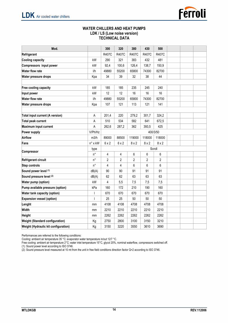
WATER CHILLERS AND HEAT PUMPS
LDK / LS (Low noise version) TECHNICAL DATA
Mod. 300 320 380 430 500
Refrigerant R407C R407C R407C R407C R407C Cooling capacity kW 290 321 383 432 481 Compressors input power kW 92,4 100,6 126,4 138,7 150,9 Water flow rate l/h 49880 55200 65800 74300 82700 Water pressure drops Kpa 34 39 32 38 44
Free cooling capacity kW 185 185 235 245 240 Input power kW 12 12 16 16 16 Water flow rate l/h 49880 55200 65800 74300 82700 Water pressure drops Kpa 107 121 113 121 141
Total input current (A version) A 201,4 220 279,2 301,7 324,2 Total peak current A 510 534 582 641 672,5 Maximum input current A 262,6 287,2 362 393,5 425 Power supply V/Ph/Hz 400/3/50 Airflow m3/h 89000 88500 119000 118000 118000 Fans n° x kW 6 x 2 6 x 2 8 x 2 8 x 2 8 x 2
type Scroll Compressor
n° 4 4 6 6 6 Refrigerant circuit n° 2 2 2 2 2 Step controls n° 4 4 6 6 6 Sound power level (1) dB(A) 90 90 91 91 91 Sound pressure level (2) dB(A) 62 62 63 63 63 Water pump (option) kW 4 5,5 7,5 7,5 7,5 Pump available pressure (option) kPa 160 172 210 190 160 Water tank capacity (option) l 670 670 670 670 670 Expansion vessel (option) l 25 25 50 50 50 Lenght mm 4108 4108 4708 4708 4708 Width mm 2210 2210 2210 2210 2210 Height mm 2262 2262 2262 2262 2262 Weight (Standard configuration) Kg 2750 2800 3100 3150 3210 Weight (Hydraulic kit configuration) Kg 3150 3220 3550 3610 3690 Performances are referred to the following conditions: Cooling: ambient air temperature 35 °C; evaporator water temperature in/out 12/7 °C. Free cooling: ambient air temperature 2°C; water inlet temperature 15°C, glycol 20%, nominal waterflow, compressors switched off. (1): Sound power level according to ISO 3746. (2): Sound pressure level measured at 10 mt from the unit in free field conditions direction factor Q=2 according to ISO 3746.
LDK Air cooled water chillers
MTLDKGB REV.112006 15
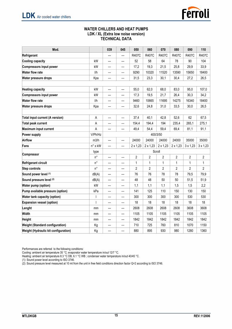
WATER CHILLERS AND HEAT PUMPS
LDK / XL (Extra low noise version) TECHNICAL DATA
Mod. 039 045 050 060 070 080 090 110
Refrigerant --- --- R407C R407C R407C R407C R407C R407C Cooling capacity kW --- --- 52 58 64 78 90 104 Compressors input power kW --- --- 17,2 19,3 21,5 25,8 29,9 33,9 Water flow rate l/h --- --- 9290 10320 11520 13590 15650 18400 Water pressure drops Kpa --- --- 31,5 23,3 30,1 30,4 27,2 26,5
Heating capacity kW --- --- 55,0 62,0 68,0 83,0 95,0 107,0 Compressors input power kW --- --- 17,3 19,5 21,7 26,4 30,3 34,2 Water flow rate l/h --- --- 9460 10665 11695 14275 16340 18400 Water pressure drops Kpa --- --- 32,6 24,8 31,0 33,5 30,0 26,5
Total input current (A version) A --- --- 37,4 40,1 42,8 52,6 62 67,5 Total peak current A --- --- 154,4 194,4 194 235,4 265,1 275,1 Maximum input current A --- --- 49,4 54,4 59,4 69,4 81,1 91,1 Power supply V/Ph/Hz 400/3/50 Airflow m3/h --- --- 24000 24000 24000 24000 35000 35000 Fans n° x kW --- --- 2 x 1,23 2 x 1,23 2 x 1,23 2 x 1,23 3 x 1,23 3 x 1,23
type Scroll Compressor
n° --- --- 2 2 2 2 2 2 Refrigerant circuit n° --- --- 1 1 1 1 1 1 Step controls n° --- --- 2 2 2 2 2 2 Sound power level (1) dB(A) --- --- 76 76 78 78 79,5 79,9 Sound pressure level (2) dB(A) --- --- 48 48 50 50 51,5 51,9 Water pump (option) kW --- --- 1,1 1,1 1,1 1,5 1,5 2,2 Pump available pressure (option) kPa --- --- 141 125 110 150 130 150 Water tank capacity (option) l --- --- 300 300 300 300 530 530 Expansion vessel (option) l --- --- 18 18 18 18 18 18 Lenght mm --- --- 2608 2608 2608 2608 3608 3608 Width mm --- --- 1105 1105 1105 1105 1105 1105 Height mm --- --- 1842 1842 1842 1842 1842 1842 Weight (Standard configuration) Kg --- --- 710 725 760 810 1070 1150 Weight (Hydraulic kit configuration) Kg --- --- 880 895 930 980 1280 1360 Performances are referred to the following conditions: Cooling: ambient air temperature 35 °C; evaporator water temperature in/out 12/7 °C. Heating: ambient air temperature 8.3 °C DB, 6.1 °C WB ; condenser water temperature in/out 40/45 °C. (1): Sound power level according to ISO 3746. (2): Sound pressure level measured at 10 mt from the unit in free field conditions direction factor Q=2 according to ISO 3746.
LDK Air cooled water chillers
MTLDKGB REV.112006 16
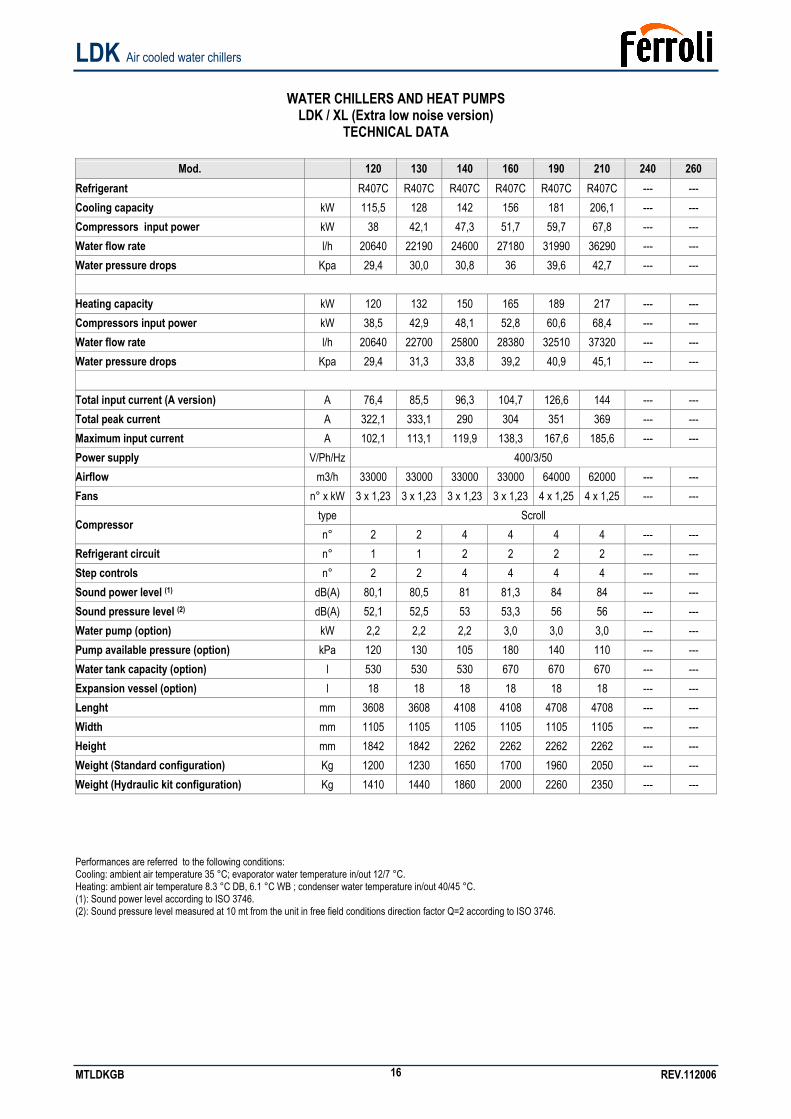
WATER CHILLERS AND HEAT PUMPS
LDK / XL (Extra low noise version) TECHNICAL DATA
Mod. 120 130 140 160 190 210 240 260
Refrigerant R407C R407C R407C R407C R407C R407C --- --- Cooling capacity kW 115,5 128 142 156 181 206,1 --- --- Compressors input power kW 38 42,1 47,3 51,7 59,7 67,8 --- --- Water flow rate l/h 20640 22190 24600 27180 31990 36290 --- --- Water pressure drops Kpa 29,4 30,0 30,8 36 39,6 42,7 --- ---
Heating capacity kW 120 132 150 165 189 217 --- --- Compressors input power kW 38,5 42,9 48,1 52,8 60,6 68,4 --- --- Water flow rate l/h 20640 22700 25800 28380 32510 37320 --- --- Water pressure drops Kpa 29,4 31,3 33,8 39,2 40,9 45,1 --- ---
Total input current (A version) A 76,4 85,5 96,3 104,7 126,6 144 --- --- Total peak current A 322,1 333,1 290 304 351 369 --- --- Maximum input current A 102,1 113,1 119,9 138,3 167,6 185,6 --- --- Power supply V/Ph/Hz 400/3/50 Airflow m3/h 33000 33000 33000 33000 64000 62000 --- --- Fans n° x kW 3 x 1,23 3 x 1,23 3 x 1,23 3 x 1,23 4 x 1,25 4 x 1,25 --- ---
type Scroll Compressor
n° 2 2 4 4 4 4 --- --- Refrigerant circuit n° 1 1 2 2 2 2 --- --- Step controls n° 2 2 4 4 4 4 --- --- Sound power level (1) dB(A) 80,1 80,5 81 81,3 84 84 --- --- Sound pressure level (2) dB(A) 52,1 52,5 53 53,3 56 56 --- --- Water pump (option) kW 2,2 2,2 2,2 3,0 3,0 3,0 --- --- Pump available pressure (option) kPa 120 130 105 180 140 110 --- --- Water tank capacity (option) l 530 530 530 670 670 670 --- --- Expansion vessel (option) l 18 18 18 18 18 18 --- --- Lenght mm 3608 3608 4108 4108 4708 4708 --- --- Width mm 1105 1105 1105 1105 1105 1105 --- --- Height mm 1842 1842 2262 2262 2262 2262 --- --- Weight (Standard configuration) Kg 1200 1230 1650 1700 1960 2050 --- --- Weight (Hydraulic kit configuration) Kg 1410 1440 1860 2000 2260 2350 --- --- Performances are referred to the following conditions: Cooling: ambient air temperature 35 °C; evaporator water temperature in/out 12/7 °C. Heating: ambient air temperature 8.3 °C DB, 6.1 °C WB ; condenser water temperature in/out 40/45 °C. (1): Sound power level according to ISO 3746. (2): Sound pressure level measured at 10 mt from the unit in free field conditions direction factor Q=2 according to ISO 3746.
LDK Air cooled water chillers
MTLDKGB REV.112006 17
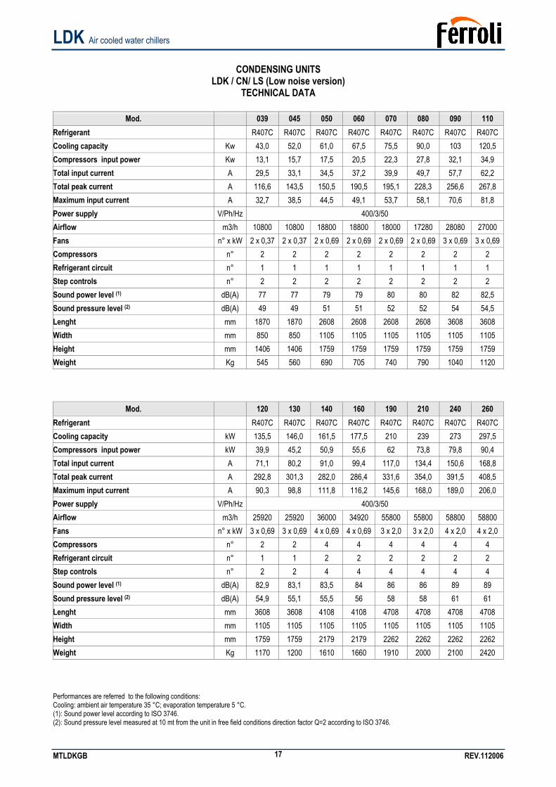
CONDENSING UNITS
LDK / CN/ LS (Low noise version) TECHNICAL DATA
Mod. 039 045 050 060 070 080 090 110
Refrigerant R407C R407C R407C R407C R407C R407C R407C R407C Cooling capacity Kw 43,0 52,0 61,0 67,5 75,5 90,0 103 120,5 Compressors input power Kw 13,1 15,7 17,5 20,5 22,3 27,8 32,1 34,9 Total input current A 29,5 33,1 34,5 37,2 39,9 49,7 57,7 62,2 Total peak current A 116,6 143,5 150,5 190,5 195,1 228,3 256,6 267,8 Maximum input current A 32,7 38,5 44,5 49,1 53,7 58,1 70,6 81,8 Power supply V/Ph/Hz 400/3/50 Airflow m3/h 10800 10800 18800 18800 18000 17280 28080 27000 Fans n° x kW 2 x 0,37 2 x 0,37 2 x 0,69 2 x 0,69 2 x 0,69 2 x 0,69 3 x 0,69 3 x 0,69 Compressors n° 2 2 2 2 2 2 2 2 Refrigerant circuit n° 1 1 1 1 1 1 1 1 Step controls n° 2 2 2 2 2 2 2 2 Sound power level (1) dB(A) 77 77 79 79 80 80 82 82,5 Sound pressure level (2) dB(A) 49 49 51 51 52 52 54 54,5 Lenght mm 1870 1870 2608 2608 2608 2608 3608 3608 Width mm 850 850 1105 1105 1105 1105 1105 1105 Height mm 1406 1406 1759 1759 1759 1759 1759 1759 Weight Kg 545 560 690 705 740 790 1040 1120
Mod. 120 130 140 160 190 210 240 260 Refrigerant R407C R407C R407C R407C R407C R407C R407C R407C Cooling capacity kW 135,5 146,0 161,5 177,5 210 239 273 297,5 Compressors input power kW 39,9 45,2 50,9 55,6 62 73,8 79,8 90,4 Total input current A 71,1 80,2 91,0 99,4 117,0 134,4 150,6 168,8 Total peak current A 292,8 301,3 282,0 286,4 331,6 354,0 391,5 408,5 Maximum input current A 90,3 98,8 111,8 116,2 145,6 168,0 189,0 206,0 Power supply V/Ph/Hz 400/3/50 Airflow m3/h 25920 25920 36000 34920 55800 55800 58800 58800 Fans n° x kW 3 x 0,69 3 x 0,69 4 x 0,69 4 x 0,69 3 x 2,0 3 x 2,0 4 x 2,0 4 x 2,0 Compressors n° 2 2 4 4 4 4 4 4 Refrigerant circuit n° 1 1 2 2 2 2 2 2 Step controls n° 2 2 4 4 4 4 4 4 Sound power level (1) dB(A) 82,9 83,1 83,5 84 86 86 89 89 Sound pressure level (2) dB(A) 54,9 55,1 55,5 56 58 58 61 61 Lenght mm 3608 3608 4108 4108 4708 4708 4708 4708 Width mm 1105 1105 1105 1105 1105 1105 1105 1105 Height mm 1759 1759 2179 2179 2262 2262 2262 2262 Weight Kg 1170 1200 1610 1660 1910 2000 2100 2420 Performances are referred to the following conditions: Cooling: ambient air temperature 35 °C; evaporation temperature 5 °C. (1): Sound power level according to ISO 3746. (2): Sound pressure level measured at 10 mt from the unit in free field conditions direction factor Q=2 according to ISO 3746.
LDK Air cooled water chillers
MTLDKGB REV.112006 18
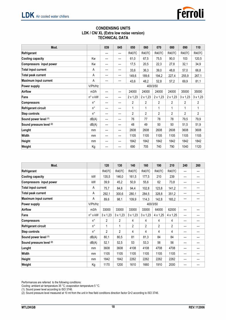
CONDENSING UNITS
LDK / CN/ XL (Extra low noise version) TECHNICAL DATA
Mod. 039 045 050 060 070 080 090 110
Refrigerant --- --- R407C R407C R407C R407C R407C R407C Cooling capacity Kw --- --- 61,0 67,5 75,5 90,0 103 120,5 Compressors input power Kw --- --- 17,5 20,5 22,3 27,8 32,1 34,9 Total input current A --- --- 33,6 36,3 39,0 48,8 57,0 66,8 Total peak current A --- --- 149,6 189,6 194,2 227,4 255,9 267,1 Maximum input current A --- --- 43,6 48,2 52,8 57,2 69,9 81,1 Power supply V/Ph/Hz 400/3/50 Airflow m3/h --- --- 24000 24000 24000 24000 35000 35000 Fans n° x kW --- --- 2 x 1,23 2 x 1,23 2 x 1,23 2 x 1,23 3 x 1,23 3 x 1,23 Compressors n° --- --- 2 2 2 2 2 2 Refrigerant circuit n° --- --- 1 1 1 1 1 1 Step controls n° --- --- 2 2 2 2 2 2 Sound power level (1) dB(A) --- --- 76 77 78 78 79,5 79,9 Sound pressure level (2) dB(A) --- --- 48 49 50 50 51,5 51,9 Lenght mm --- --- 2608 2608 2608 2608 3608 3608 Width mm --- --- 1105 1105 1105 1105 1105 1105 Height mm --- --- 1842 1842 1842 1842 1842 1842 Weight Kg --- --- 690 705 740 790 1040 1120
Mod. 120 130 140 160 190 210 240 260 Refrigerant R407C R407C R407C R407C R407C R407C --- --- Cooling capacity kW 135,5 146,0 161,5 177,5 210 239 --- --- Compressors input power kW 39,9 45,2 50,9 55,6 62 73,8 --- --- Total input current A 75,7 84,8 94,4 102,8 123,8 141,2 --- --- Total peak current A 292,1 300,6 280,1 284,5 328,8 351,2 --- --- Maximum input current A 89,6 98,1 109,9 114,3 142,8 165,2 --- --- Power supply V/Ph/Hz 400/3/50 Airflow m3/h 33000 33000 33000 33000 64000 62000 --- --- Fans n° x kW 3 x 1,23 3 x 1,23 3 x 1,23 3 x 1,23 4 x 1,25 4 x 1,25 --- --- Compressors n° 2 2 4 4 4 4 --- --- Refrigerant circuit n° 1 1 2 2 2 2 --- --- Step controls n° 2 2 4 4 4 4 --- --- Sound power level (1) dB(A) 80,1 80,5 81 81,3 84 84 --- --- Sound pressure level (2) dB(A) 52,1 52,5 53 53,3 56 56 --- --- Lenght mm 3608 3608 4108 4108 4708 4708 --- --- Width mm 1105 1105 1105 1105 1105 1105 --- --- Height mm 1842 1842 2262 2262 2262 2262 --- --- Weight Kg 1170 1200 1610 1660 1910 2000 --- --- Performances are referred to the following conditions: Cooling: ambient air temperature 35 °C; evaporation temperature 5 °C. (1): Sound power level according to ISO 3746. (2): Sound pressure level measured at 10 mt from the unit in free field conditions direction factor Q=2 according to ISO 3746.
LDK Air cooled water chillers
MTLDKGB REV.112006 19
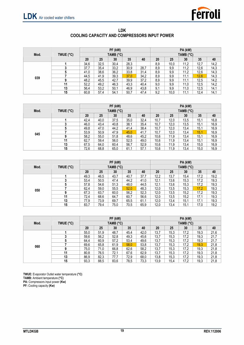
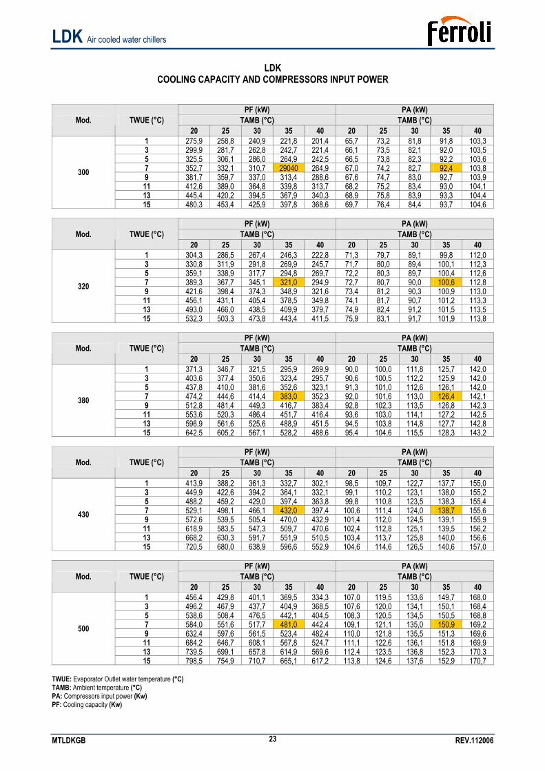
LDK
COOLING CAPACITY AND COMPRESSORS INPUT POWER
PF (kW) PA (kW) TAMB (°C) TAMB (°C) Mod. TWUE (°C)
20 25 30 35 40 20 25 30 35 40 1 34,6 32,5 30,4 28,3 8,9 10,0 11,2 12,7 14,2 3 37,7 35,4 33,2 30,9 28,7 8,9 9,9 11,2 12,6 14,3 5 41,0 38,6 36,2 33,8 31,4 8,9 9,9 11,2 12,6 14,3 7 44,5 41,9 39,3 37,0 34,2 8,9 9,9 11,1 12,6 14,3 9 48,2 45,5 42,7 39,9 37,2 8,9 9,9 11,1 12,5 14,2 11 52,2 49,2 46,3 43,3 40,4 9,0 9,9 11,0 12,5 14,2 13 56,4 53,2 50,1 46,9 43,8 9,1 9,9 11,0 12,5 14,1
039
15 60,8 57,4 54,1 50,7 47,4 9,2 10,0 11,1 12,4 14,1
PF (kW) PA (kW) TAMB (°C) TAMB (°C) Mod. TWUE (°C)
20 25 30 35 40 20 25 30 35 40 1 42,4 40,0 37,5 35,0 32,4 10,7 12,0 13,5 15,1 16,8 3 46,0 43,4 40,8 38,1 35,4 10,7 12,0 13,5 15,1 16,9 5 49,8 47,0 44,2 41,4 38,4 10,7 12,0 13,4 15,1 16,9 7 53,9 50,9 47,9 45,0 41,7 10,7 12,0 13,4 15,1 16,9 9 58,2 55,0 51,8 48,6 45,2 10,6 11,9 13,4 15,1 16,9 11 62,7 59,4 56,0 52,5 49,0 10,6 11,9 13,4 15,1 16,9 13 67,5 64,0 60,4 56,7 52,9 10,6 11,9 13,4 15,0 16,9
045
15 72,6 68,8 65,0 61,1 57,1 10,6 11,9 13,4 15,0 16,9
PF (kW) PA (kW) TAMB (°C) TAMB (°C) Mod. TWUE (°C)
20 25 30 35 40 20 25 30 35 40 1 49,3 46,5 43,7 40,7 37,7 12,2 13,7 15,4 17,2 19,2 3 53,4 50,5 47,4 44,2 41,0 12,1 13,6 15,3 17,2 19,3 5 57,8 54,6 51,3 48,0 44,5 12,1 13,6 15,3 17,2 19,3 7 62,4 59,0 55,5 52,0 48,3 12,0 13,5 15,3 17,2 19,3 9 67,3 63,7 60,0 56,2 52,3 12,0 13,5 15,2 17,2 19,3 11 72,4 68,6 64,7 60,7 56,6 12,0 13,5 15,2 17,1 19,3 13 77,9 73,9 69,7 65,5 61,1 12,0 13,4 15,1 17,1 19,3
050
15 83,7 79,4 75,0 70,5 65,9 12,0 13,4 15,1 17,0 19,2
PF (kW) PA (kW) TAMB (°C) TAMB (°C) Mod. TWUE (°C)
20 25 30 35 40 20 25 30 35 40 1 55,0 51,9 48,7 45,4 42,0 13,7 15,3 17,2 19,3 21,6 3 59,6 56,2 52,8 49,3 45,6 13,7 15,3 17,2 19,3 21,7 5 64,4 60,9 57,2 53,4 49,6 13,7 15,3 17,2 19,3 21,7 7 69,6 65,8 61,9 58,0 53,8 13,7 15,3 17,2 19,3 21,8 9 75,0 71,0 66,8 62,6 58,2 13,7 15,3 17,2 19,3 21,8 11 80,8 76,5 72,1 67,6 62,9 13,7 15,3 17,2 19,3 21,8 13 86,9 82,3 77,7 72,9 68,0 13,8 15,3 17,2 19,3 21,8
060
15 93,3 88,5 83,6 78,5 73,3 13,9 15,4 17,2 19,3 21,8 TWUE: Evaporator Outlet water temperature (°C) TAMB: Ambient temperature (°C) PA: Compressors input power (Kw) PF: Cooling capacity (Kw)
LDK Air cooled water chillers
MTLDKGB REV.112006 20
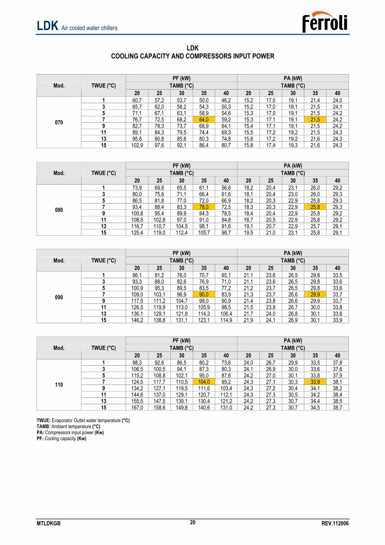
LDK
COOLING CAPACITY AND COMPRESSORS INPUT POWER
PF (kW) PA (kW) TAMB (°C) TAMB (°C) Mod. TWUE (°C)
20 25 30 35 40 20 25 30 35 40 1 60,7 57,2 53,7 50,0 46,2 15,2 17,0 19,1 21,4 24,0 3 65,7 62,0 58,2 54,3 50,3 15,2 17,0 19,1 21,5 24,1 5 71,1 67,1 63,1 58,9 54,6 15,3 17,0 19,1 21,5 24,2 7 76,7 72,5 68,2 64,0 59,2 15,3 17,1 19,1 21,5 24,2 9 82,7 78,3 73,7 68,9 64,1 15,4 17,1 19,1 21,5 24,2 11 89,1 84,3 79,5 74,4 69,3 15,5 17,2 19,2 21,5 24,3 13 95,8 90,8 85,6 80,3 74,8 15,6 17,2 19,2 21,6 24,3
070
15 102,9 97,6 92,1 86,4 80,7 15,8 17,4 19,3 21,6 24,3
PF (kW) PA (kW) TAMB (°C) TAMB (°C) Mod. TWUE (°C)
20 25 30 35 40 20 25 30 35 40 1 73,9 69,8 65,5 61,1 56,6 18,2 20,4 23,1 26,0 29,2 3 80,0 75,6 71,1 66,4 61,6 18,1 20,4 23,0 26,0 29,3 5 86,5 81,8 77,0 72,0 66,9 18,2 20,3 22,9 25,8 29,3 7 93,4 88,4 83,3 78,0 72,5 18,3 20,3 22,9 25,8 29,3 9 100,8 95,4 89,9 84,3 78,5 18,4 20,4 22,9 25,8 29,2 11 108,5 102,8 97,0 91,0 84,8 18,7 20,5 22,9 25,8 29,2 13 116,7 110,7 104,5 98,1 91,6 19,1 20,7 22,9 25,7 29,1
080
15 125,4 119,0 112,4 105,7 98,7 19,5 21,0 23,1 25,8 29,1
PF (kW) PA (kW) TAMB (°C) TAMB (°C) Mod. TWUE (°C)
20 25 30 35 40 20 25 30 35 40 1 86,1 81,2 76,0 70,7 65,1 21,1 23,6 26,5 29,8 33,5 3 93,3 88,0 82,6 76,9 71,0 21,1 23,6 26,5 29,8 33,6 5 100,9 95,3 89,5 83,5 77,2 21,2 23,7 26,5 29,8 33,6 7 109,0 103,1 96,9 90,0 83,9 21,3 23,7 26,6 29,9 33,7 9 117,5 111,2 104,7 98,0 90,9 21,4 23,8 26,6 29,9 33,7 11 126,5 119,9 113,0 105,9 98,5 21,5 23,9 26,7 30,0 33,8 13 136,1 129,1 121,8 114,3 106,4 21,7 24,0 26,8 30,1 33,8
090
15 146,2 138,8 131,1 123,1 114,9 21,9 24,1 26,9 30,1 33,9
PF (kW) PA (kW) TAMB (°C) TAMB (°C) Mod. TWUE (°C)
20 25 30 35 40 20 25 30 35 40 1 98,3 92,6 86,5 80,2 73,6 24,0 26,7 29,9 33,5 37,8 3 106,5 100,5 94,1 87,3 80,3 24,1 26,9 30,0 33,6 37,8 5 115,2 108,8 102,1 95,0 87,6 24,2 27,0 30,1 33,8 37,9 7 124,5 117,7 110,5 104,0 95,2 24,3 27,1 30,3 33,9 38,1 9 134,2 127,1 119,5 111,6 103,4 24,3 27,2 30,4 34,1 38,2 11 144,6 137,0 129,1 120,7 112,1 24,3 27,3 30,5 34,2 38,4 13 155,5 147,5 139,1 130,4 121,2 24,2 27,3 30,7 34,4 38,5
110
15 167,0 158,6 149,8 140,6 131,0 24,2 27,3 30,7 34,5 38,7 TWUE: Evaporator Outlet water temperature (°C) TAMB: Ambient temperature (°C) PA: Compressors input power (Kw) PF: Cooling capacity (Kw)
LDK Air cooled water chillers
MTLDKGB REV.112006 21
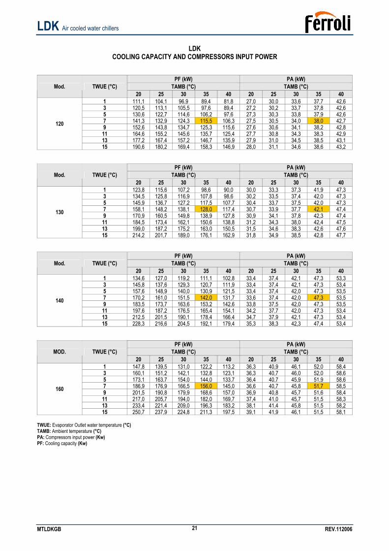
LDK
COOLING CAPACITY AND COMPRESSORS INPUT POWER
PF (kW) PA (kW) TAMB (°C) TAMB (°C) Mod. TWUE (°C)
20 25 30 35 40 20 25 30 35 40 1 111,1 104,1 96,9 89,4 81,8 27,0 30,0 33,6 37,7 42,6 3 120,5 113,1 105,5 97,6 89,4 27,2 30,2 33,7 37,8 42,6 5 130,6 122,7 114,6 106,2 97,6 27,3 30,3 33,8 37,9 42,6 7 141,3 132,9 124,3 115,5 106,3 27,5 30,5 34,0 38,0 42,7 9 152,6 143,8 134,7 125,3 115,6 27,6 30,6 34,1 38,2 42,8 11 164,6 155,2 145,6 135,7 125,4 27,7 30,8 34,3 38,3 42,9 13 177,2 167,4 157,2 146,7 135,9 27,9 31,0 34,5 38,5 43,1
120
15 190,6 180,2 169,4 158,3 146,9 28,0 31,1 34,6 38,6 43,2
PF (kW) PA (kW) TAMB (°C) TAMB (°C) Mod. TWUE (°C)
20 25 30 35 40 20 25 30 35 40 1 123,8 115,6 107,2 98,6 90,0 30,0 33,3 37,3 41,9 47,3 3 134,5 125,8 116,9 107,8 98,6 30,2 33,5 37,4 42,0 47,3 5 145,9 136,7 127,2 117,5 107,7 30,4 33,7 37,5 42,0 47,3 7 158,1 148,2 138,1 128,0 117,4 30,7 33,9 37,7 42,1 47,4 9 170,9 160,5 149,8 138,9 127,8 30,9 34,1 37,8 42,3 47,4 11 184,5 173,4 162,1 150,6 138,8 31,2 34,3 38,0 42,4 47,5 13 199,0 187,2 175,2 163,0 150,5 31,5 34,6 38,3 42,6 47,6
130
15 214,2 201,7 189,0 176,1 162,9 31,8 34,9 38,5 42,8 47,7
PF (kW) PA (kW) TAMB (°C) TAMB (°C) Mod. TWUE (°C)
20 25 30 35 40 20 25 30 35 40 1 134,6 127,0 119,2 111,1 102,8 33,4 37,4 42,1 47,3 53,3 3 145,8 137,6 129,3 120,7 111,9 33,4 37,4 42,1 47,3 53,4 5 157,6 148,9 140,0 130,9 121,5 33,4 37,4 42,0 47,3 53,5 7 170,2 161,0 151,5 142,0 131,7 33,6 37,4 42,0 47,3 53,5 9 183,5 173,7 163,6 153,2 142,6 33,8 37,5 42,0 47,3 53,5 11 197,6 187,2 176,5 165,4 154,1 34,2 37,7 42,0 47,3 53,4 13 212,5 201,5 190,1 178,4 166,4 34,7 37,9 42,1 47,3 53,4
140
15 228,3 216,6 204,5 192,1 179,4 35,3 38,3 42,3 47,4 53,4
PF (kW) PA (kW) TAMB (°C) TAMB (°C) MOD. TWUE (°C)
20 25 30 35 40 20 25 30 35 40 1 147,8 139,5 131,0 122,2 113,2 36,3 40,9 46,1 52,0 58,4 3 160,1 151,2 142,1 132,8 123,1 36,3 40,7 46,0 52,0 58,6 5 173,1 163,7 154,0 144,0 133,7 36,4 40,7 45,9 51,9 58,6 7 186,9 176,9 166,5 156,0 145,0 36,6 40,7 45,8 51,7 58,5 9 201,5 190,8 179,9 168,6 157,0 36,9 40,8 45,7 51,6 58,4 11 217,0 205,7 194,0 182,0 169,7 37,4 41,0 45,7 51,5 58,3 13 233,4 221,4 209,0 196,3 183,2 38,1 41,4 45,8 51,5 58,2
160
15 250,7 237,9 224,8 211,3 197,5 39,1 41,9 46,1 51,5 58,1 TWUE: Evaporator Outlet water temperature (°C) TAMB: Ambient temperature (°C) PA: Compressors input power (Kw) PF: Cooling capacity (Kw)
LDK Air cooled water chillers
MTLDKGB REV.112006 22
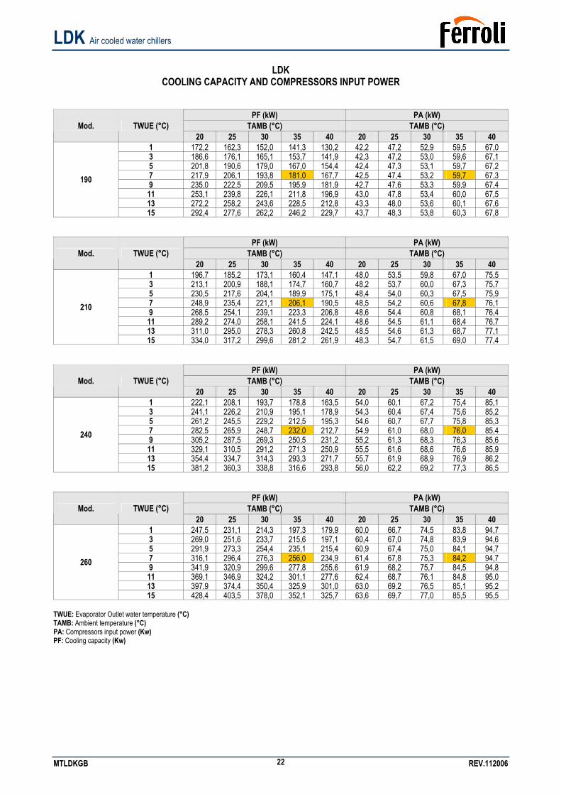
LDK
COOLING CAPACITY AND COMPRESSORS INPUT POWER
PF (kW) PA (kW) TAMB (°C) TAMB (°C) Mod. TWUE (°C)
20 25 30 35 40 20 25 30 35 40 1 172,2 162,3 152,0 141,3 130,2 42,2 47,2 52,9 59,5 67,0 3 186,6 176,1 165,1 153,7 141,9 42,3 47,2 53,0 59,6 67,1 5 201,8 190,6 179,0 167,0 154,4 42,4 47,3 53,1 59,7 67,2 7 217,9 206,1 193,8 181,0 167,7 42,5 47,4 53,2 59,7 67,3 9 235,0 222,5 209,5 195,9 181,9 42,7 47,6 53,3 59,9 67,4 11 253,1 239,8 226,1 211,8 196,9 43,0 47,8 53,4 60,0 67,5 13 272,2 258,2 243,6 228,5 212,8 43,3 48,0 53,6 60,1 67,6
190
15 292,4 277,6 262,2 246,2 229,7 43,7 48,3 53,8 60,3 67,8
PF (kW) PA (kW) TAMB (°C) TAMB (°C) Mod. TWUE (°C)
20 25 30 35 40 20 25 30 35 40 1 196,7 185,2 173,1 160,4 147,1 48,0 53,5 59,8 67,0 75,5 3 213,1 200,9 188,1 174,7 160,7 48,2 53,7 60,0 67,3 75,7 5 230,5 217,6 204,1 189,9 175,1 48,4 54,0 60,3 67,5 75,9 7 248,9 235,4 221,1 206,1 190,5 48,5 54,2 60,6 67,8 76,1 9 268,5 254,1 239,1 223,3 206,8 48,6 54,4 60,8 68,1 76,4 11 289,2 274,0 258,1 241,5 224,1 48,6 54,5 61,1 68,4 76,7 13 311,0 295,0 278,3 260,8 242,5 48,5 54,6 61,3 68,7 77,1
210
15 334,0 317,2 299,6 281,2 261,9 48,3 54,7 61,5 69,0 77,4
PF (kW) PA (kW) TAMB (°C) TAMB (°C) Mod. TWUE (°C)
20 25 30 35 40 20 25 30 35 40 1 222,1 208,1 193,7 178,8 163,5 54,0 60,1 67,2 75,4 85,1 3 241,1 226,2 210,9 195,1 178,9 54,3 60,4 67,4 75,6 85,2 5 261,2 245,5 229,2 212,5 195,3 54,6 60,7 67,7 75,8 85,3 7 282,5 265,9 248,7 232,0 212,7 54,9 61,0 68,0 76,0 85,4 9 305,2 287,5 269,3 250,5 231,2 55,2 61,3 68,3 76,3 85,6 11 329,1 310,5 291,2 271,3 250,9 55,5 61,6 68,6 76,6 85,9 13 354,4 334,7 314,3 293,3 271,7 55,7 61,9 68,9 76,9 86,2
240
15 381,2 360,3 338,8 316,6 293,8 56,0 62,2 69,2 77,3 86,5
PF (kW) PA (kW) TAMB (°C) TAMB (°C) Mod. TWUE (°C)
20 25 30 35 40 20 25 30 35 40 1 247,5 231,1 214,3 197,3 179,9 60,0 66,7 74,5 83,8 94,7 3 269,0 251,6 233,7 215,6 197,1 60,4 67,0 74,8 83,9 94,6 5 291,9 273,3 254,4 235,1 215,4 60,9 67,4 75,0 84,1 94,7 7 316,1 296,4 276,3 256,0 234,9 61,4 67,8 75,3 84,2 94,7 9 341,9 320,9 299,6 277,8 255,6 61,9 68,2 75,7 84,5 94,8 11 369,1 346,9 324,2 301,1 277,6 62,4 68,7 76,1 84,8 95,0 13 397,9 374,4 350,4 325,9 301,0 63,0 69,2 76,5 85,1 95,2
260
15 428,4 403,5 378,0 352,1 325,7 63,6 69,7 77,0 85,5 95,5 TWUE: Evaporator Outlet water temperature (°C) TAMB: Ambient temperature (°C) PA: Compressors input power (Kw) PF: Cooling capacity (Kw)
LDK Air cooled water chillers
MTLDKGB REV.112006 23
LDK
COOLING CAPACITY AND COMPRESSORS INPUT POWER
PF (kW) PA (kW) TAMB (°C) TAMB (°C) Mod. TWUE (°C)
20 25 30 35 40 20 25 30 35 40 1 275,9 258,8 240,9 221,8 201,4 65,7 73,2 81,8 91,8 103,3 3 299,9 281,7 262,8 242,7 221,4 66,1 73,5 82,1 92,0 103,5 5 325,5 306,1 286,0 264,9 242,5 66,5 73,8 82,3 92,2 103,6 7 352,7 332,1 310,7 29040 264,9 67,0 74,2 82,7 92,4 103,8 9 381,7 359,7 337,0 313,4 288,6 67,6 74,7 83,0 92,7 103,9 11 412,6 389,0 364,8 339,8 313,7 68,2 75,2 83,4 93,0 104,1 13 445,4 420,2 394,5 367,9 340,3 68,9 75,8 83,9 93,3 104,4
300
15 480,3 453,4 425,9 397,8 368,6 69,7 76,4 84,4 93,7 104,6
PF (kW) PA (kW) TAMB (°C) TAMB (°C) Mod. TWUE (°C)
20 25 30 35 40 20 25 30 35 40 1 304,3 286,5 267,4 246,3 222,8 71,3 79,7 89,1 99,8 112,0 3 330,8 311,9 291,8 269,9 245,7 71,7 80,0 89,4 100,1 112,3 5 359,1 338,9 317,7 294,8 269,7 72,2 80,3 89,7 100,4 112,6 7 389,3 367,7 345,1 321,0 294,9 72,7 80,7 90,0 100,6 112,8 9 421,6 398,4 374,3 348,9 321,6 73,4 81,2 90,3 100,9 113,0 11 456,1 431,1 405,4 378,5 349,8 74,1 81,7 90,7 101,2 113,3 13 493,0 466,0 438,5 409,9 379,7 74,9 82,4 91,2 101,5 113,5
320
15 532,3 503,3 473,8 443,4 411,5 75,9 83,1 91,7 101,9 113,8
PF (kW) PA (kW) TAMB (°C) TAMB (°C) Mod. TWUE (°C)
20 25 30 35 40 20 25 30 35 40 1 371,3 346,7 321,5 295,9 269,9 90,0 100,0 111,8 125,7 142,0 3 403,6 377,4 350,6 323,4 295,7 90,6 100,5 112,2 125,9 142,0 5 437,8 410,0 381,6 352,6 323,1 91,3 101,0 112,6 126,1 142,0 7 474,2 444,6 414,4 383,0 352,3 92,0 101,6 113,0 126,4 142,1 9 512,8 481,4 449,3 416,7 383,4 92,8 102,3 113,5 126,8 142,3 11 553,6 520,3 486,4 451,7 416,4 93,6 103,0 114,1 127,2 142,5 13 596,9 561,6 525,6 488,9 451,5 94,5 103,8 114,8 127,7 142,8
380
15 642,5 605,2 567,1 528,2 488,6 95,4 104,6 115,5 128,3 143,2
PF (kW) PA (kW) TAMB (°C) TAMB (°C) Mod. TWUE (°C)
20 25 30 35 40 20 25 30 35 40 1 413,9 388,2 361,3 332,7 302,1 98,5 109,7 122,7 137,7 155,0 3 449,9 422,6 394,2 364,1 332,1 99,1 110,2 123,1 138,0 155,2 5 488,2 459,2 429,0 397,4 363,8 99,8 110,8 123,5 138,3 155,4 7 529,1 498,1 466,1 432,0 397,4 100,6 111,4 124,0 138,7 155,6 9 572,6 539,5 505,4 470,0 432,9 101,4 112,0 124,5 139,1 155,9 11 618,9 583,5 547,3 509,7 470,6 102,4 112,8 125,1 139,5 156,2 13 668,2 630,3 591,7 551,9 510,5 103,4 113,7 125,8 140,0 156,6
430
15 720,5 680,0 638,9 596,6 552,9 104,6 114,6 126,5 140,6 157,0
PF (kW) PA (kW) TAMB (°C) TAMB (°C) Mod. TWUE (°C)
20 25 30 35 40 20 25 30 35 40 1 456,4 429,8 401,1 369,5 334,3 107,0 119,5 133,6 149,7 168,0 3 496,2 467,9 437,7 404,9 368,5 107,6 120,0 134,1 150,1 168,4 5 538,6 508,4 476,5 442,1 404,5 108,3 120,5 134,5 150,5 168,8 7 584,0 551,6 517,7 481,0 442,4 109,1 121,1 135,0 150,9 169,2 9 632,4 597,6 561,5 523,4 482,4 110,0 121,8 135,5 151,3 169,6 11 684,2 646,7 608,1 567,8 524,7 111,1 122,6 136,1 151,8 169,9 13 739,5 699,1 657,8 614,9 569,6 112,4 123,5 136,8 152,3 170,3
500
15 798,5 754,9 710,7 665,1 617,2 113,8 124,6 137,6 152,9 170,7 TWUE: Evaporator Outlet water temperature (°C) TAMB: Ambient temperature (°C) PA: Compressors input power (Kw) PF: Cooling capacity (Kw)
LDK Air cooled water chillers
MTLDKGB REV.112006 24
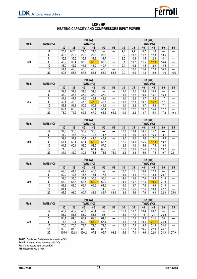
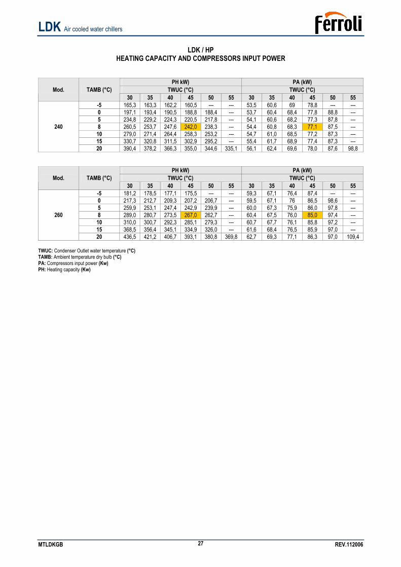
LDK / HP
HEATING CAPACITY AND COMPRESSORS INPUT POWER
PH kW) PA (kW) TWUC (°C) TWUC (°C) Mod. TAMB (°C)
30 35 40 45 50 55 30 35 40 45 50 55 -5 25,1 24,7 24,5 24,3 --- --- 9,1 9,9 10,7 11,6 --- --- 0 30,3 29,8 29,5 29,3 20,3 --- 9,2 10,2 11,2 12,3 13,5 --- 5 36,2 35,6 35,1 34,9 31,7 --- 9,2 10,3 11,5 12,8 14,1 --- 8 40,2 39,4 38,8 38,5 38,2 --- 9,1 10,2 11,5 12,9 14,4 --- 10 43,0 42,2 41,5 41,0 40,7 --- 9,1 10,2 11,5 12,9 14,5 --- 15 51,1 49,8 48,8 48,0 47,5 --- 9,0 10,1 11,4 12,9 14,6 ---
039
20 60,5 58,8 57,3 56,1 55,2 54,5 9,0 10,0 11,3 12,9 14,6 16,6
PH kW) PA (kW) TWUC (°C) TWUC (°C) Mod. TAMB (°C)
30 35 40 45 50 55 30 35 40 45 50 55 -5 32,1 31,9 31,8 31,8 --- --- 11,0 12,1 13,4 14,9 --- --- 0 37,9 37,5 37,2 37,0 37,0 --- 11,0 12,2 13,6 15,1 16,8 --- 5 44,8 44,1 43,5 43,1 42,8 --- 11,0 12,3 13,7 15,2 17 --- 8 49,4 48,6 47,8 47,0 46,7 --- 11,0 12,3 13,7 15,2 17 --- 10 52,8 51,8 50,9 50,2 49,6 --- 11,0 12,3 13,7 15,3 17,1 --- 15 62,1 60,8 59,5 58,4 57,4 --- 10,9 12,2 13,7 15,4 17,2 ---
045
20 73,0 71,2 69,5 67,9 66,5 65,2 10,9 12,2 13,7 15,4 17,2 19,3
PH kW) PA (kW) TWUC (°C) TWUC (°C) Mod. TAMB (°C)
30 35 40 45 50 55 30 35 40 45 50 55 -5 37,3 36,8 36,2 35,6 --- --- 12,3 13,4 14,5 15,7 --- --- 0 44,2 43,6 42,9 42,3 41,7 --- 12,5 14,0 15,2 16,6 18,1 --- 5 52,1 51,2 50,4 49,7 48,9 --- 12,5 14,0 15,6 17,1 18,9 --- 8 57,4 56,4 55,4 55,0 53,7 --- 12,5 14,0 15,6 17,3 19,2 --- 10 61,2 60,1 59,0 58,0 57,0 --- 12,5 14,0 15,6 17,5 19,4 --- 15 71,8 70,2 68,8 67,4 66,2 --- 12,3 13,9 15,6 17,6 19,7 ---
050
20 84,1 82,0 80,1 78,3 76,6 75,0 12,2 13,8 15,6 17,5 19,7 22,1
PH kW) PA (kW) TWUC (°C) TWUC (°C) Mod. TAMB (°C)
30 35 40 45 50 55 30 35 40 45 50 55 -5 42,3 41,7 41,2 40,7 --- --- 13,7 15 16,4 17,9 --- --- 0 50,0 49,3 48,7 48,1 47,6 --- 13,9 15,4 17,1 18,8 20,7 --- 5 59,0 58,0 57,1 56,3 55,6 --- 14,0 15,6 17,4 19,3 21,4 --- 8 65,0 63,8 62,7 62,0 60,9 --- 14,0 15,7 17,5 19,5 21,8 --- 10 69,3 68,0 66,7 65,6 64,6 --- 14,0 15,7 17,6 19,6 21,9 --- 15 81,4 79,5 77,8 76,3 74,9 --- 13,9 15,6 17,6 19,8 22,2 ---
060
20 95,5 93,0 90,7 88,6 86,7 84,9 13,9 15,6 17,6 19,8 22,3 25,0
PH kW) PA (kW) TWUC (°C) TWUC (°C) Mod. TAMB (°C)
30 35 40 45 50 55 30 35 40 45 50 55 -5 46,7 46,2 45,7 45,4 --- --- 15,1 16,7 18,4 20,2 --- --- 0 55,2 54,5 53,9 53,4 53 --- 15,4 17,1 19 21 23,2 --- 5 65,1 64,0 63,1 62,3 61,7 --- 15,5 17,3 19,3 21,5 24 --- 8 71,8 70,4 69,2 68,0 67,4 --- 15,5 17,3 19,4 21,7 24,3 --- 10 76,6 75,0 73,7 72,5 71,5 --- 15,5 17,3 19,5 21,8 24,4 --- 15 90,0 87,8 85,9 84,2 82,7 --- 15,5 17,4 19,5 22,0 24,7 ---
070
20 105,6 102,8 100,2 97,8 95,7 93,8 15,6 17,4 19,6 22,0 24,8 27,9 TWUC: Condenser Outlet water temperature (°C) TAMB: Ambient temperature dry bulb (°C) PA: Compressors input power (Kw) PH: Heating capacity (Kw)
LDK Air cooled water chillers
MTLDKGB REV.112006 25
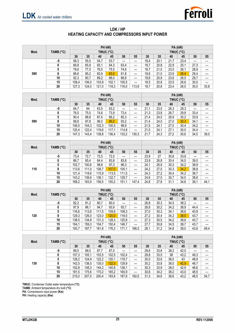
LDK / HP
HEATING CAPACITY AND COMPRESSORS INPUT POWER
PH kW) PA (kW) TWUC (°C) TWUC (°C) Mod. TAMB (°C)
30 35 40 45 50 55 30 35 40 45 50 55 -5 56,3 55,5 54,7 53,7 --- --- 18,4 20,1 21,7 23,4 --- --- 0 66,8 65,9 65,1 64,3 63,4 --- 18,7 20,8 22,9 25,1 27,3 --- 5 78,6 77,5 76,5 75,5 74,6 --- 18,7 21,0 23,5 26,1 28,9 --- 8 86,6 85,2 83,9 83,0 81,8 --- 18,6 21,0 23,6 26,4 29,4 --- 10 92,3 90,7 89,2 88,0 86,8 --- 18,6 20,9 23,6 26,5 29,7 --- 15 108,4 106,0 103,9 102,1 100,5 --- 18,5 20,8 23,5 26,6 30,0 ---
080
20 127,3 124,0 121,0 118,3 116,0 113,9 18,7 20,8 23,4 26,5 30,0 33,8
PH kW) PA (kW) TWUC (°C) TWUC (°C) Mod. TAMB (°C)
30 35 40 45 50 55 30 35 40 45 50 55 -5 64,7 64 63,5 63,2 --- --- 21,1 23,5 26,3 29,3 --- --- 0 76,5 75,5 74,6 73,9 73,4 --- 21,3 23,8 26,7 29,8 33,4 --- 5 90,4 88,8 87,4 86,2 85,3 --- 21,4 24,0 26,9 30,2 33,9 --- 8 99,8 97,8 96,0 95,0 93,2 --- 21,4 24,0 27,0 30,3 34,1 --- 10 106,5 104,3 102,3 100,5 98,9 --- 21,5 24,1 27,0 30,4 34,2 --- 15 125,4 122,4 119,6 117,1 114,8 --- 21,5 24,1 27,1 30,5 34,4 ---
090
20 147,3 143,4 139,8 136,4 133,2 130,3 21,7 24,3 27,2 30,6 34,5 39,0
PH kW) PA (kW) TWUC (°C) TWUC (°C) Mod. TAMB (°C)
30 35 40 45 50 55 30 35 40 45 50 55 -5 73,4 72,7 72,5 72,0 --- --- 23,9 27 30,8 33,8 --- --- 0 86,7 85,4 84,4 83,8 83,8 --- 23,9 26,8 30,4 34,5 39,5 --- 5 102,7 100,6 98,8 97,3 96,3 --- 24,1 26,9 30,3 34,2 38,9 --- 8 113,6 111,0 108,7 107,0 105,1 --- 24,2 27,0 30,3 34,2 38,8 --- 10 121,4 118,6 115,9 113,5 111,5 --- 24,3 27,2 30,4 34,2 38,7 --- 15 143,2 139,6 136,1 132,7 129,7 --- 24,6 27,5 30,7 34,5 38,8 ---
110
20 168,2 163,9 159,5 155,2 151,1 147,4 24,8 27,8 31,1 34,8 39,1 44,1
PH kW) PA (kW) TWUC (°C) TWUC (°C) Mod. TAMB (°C)
30 35 40 45 50 55 30 35 40 45 50 55 -5 82,2 81,2 80,7 80,0 --- --- 26,8 30,3 34,5 38,2 --- --- 0 97,9 96,1 94,7 93,9 93,7 --- 26,8 30,2 34,2 38,9 44,4 --- 5 116,6 113,8 111,5 109,6 108,3 --- 27,0 30,3 34,1 38,6 43,9 --- 8 129,3 126,0 123,0 120,0 118,5 --- 27,2 30,4 34,2 38,5 43,7 --- 10 138,5 134,8 131,3 128,3 125,8 --- 27,3 30,5 34,2 38,6 43,7 --- 15 164,1 159,3 154,7 150,4 146,7 --- 27,7 30,8 34,5 38,7 43,7 ---
120
20 193,7 187,7 181,8 176,3 171,1 166,5 28,1 31,2 34,8 39,0 43,8 49,4
PH kW) PA (kW) TWUC (°C) TWUC (°C) Mod. TAMB (°C)
30 35 40 45 50 55 30 35 40 45 50 55 -5 89,5 89,5 87,7 87,0 --- --- 29,6 33,6 38,2 42,5 --- --- 0 107,3 105,1 103,5 102,5 102,4 --- 29,8 33,5 38 43,2 49,3 --- 5 128,2 124,9 122,2 120,1 118,7 --- 30,0 33,6 38,0 43 48,9 --- 8 142,5 138,5 135,0 132,0 129,9 --- 30,2 33,8 38,0 42,9 48,7 --- 10 152,8 148,3 144,2 140,8 138,1 --- 30,3 33,9 38,0 42,9 48,6 --- 15 181,5 175,6 170,2 165,2 160,9 --- 30,8 34,2 38,2 43,0 48,5 ---
130
20 215,0 207,5 200,4 193,8 187,9 182,6 31,3 34,6 38,6 43,2 48,5 54,7 TWUC: Condenser Outlet water temperature (°C) TAMB: Ambient temperature dry bulb (°C) PA: Compressors input power (Kw) PH: Heating capacity (Kw)
LDK Air cooled water chillers
MTLDKGB REV.112006 26
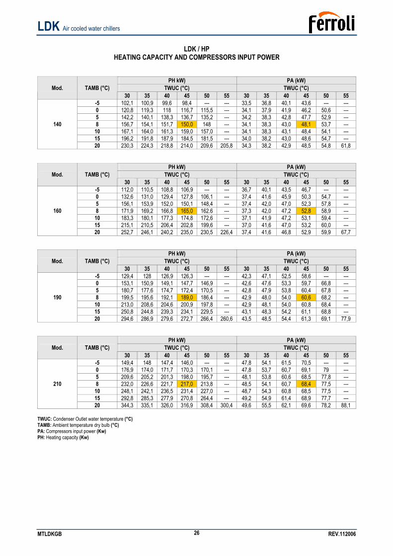
LDK / HP
HEATING CAPACITY AND COMPRESSORS INPUT POWER
PH kW) PA (kW) TWUC (°C) TWUC (°C) Mod. TAMB (°C)
30 35 40 45 50 55 30 35 40 45 50 55 -5 102,1 100,9 99,6 98,4 --- --- 33,5 36,8 40,1 43,6 --- --- 0 120,8 119,3 118 116,7 115,5 --- 34,1 37,9 41,9 46,2 50,6 --- 5 142,2 140,1 138,3 136,7 135,2 --- 34,2 38,3 42,8 47,7 52,9 --- 8 156,7 154,1 151,7 150,0 148 --- 34,1 38,3 43,0 48,1 53,7 --- 10 167,1 164,0 161,3 159,0 157,0 --- 34,1 38,3 43,1 48,4 54,1 --- 15 196,2 191,8 187,9 184,5 181,5 --- 34,0 38,2 43,0 48,6 54,7 ---
140
20 230,3 224,3 218,8 214,0 209,6 205,8 34,3 38,2 42,9 48,5 54,8 61,8
PH kW) PA (kW) TWUC (°C) TWUC (°C) Mod. TAMB (°C)
30 35 40 45 50 55 30 35 40 45 50 55 -5 112,0 110,5 108,8 106,9 --- --- 36,7 40,1 43,5 46,7 --- --- 0 132,6 131,0 129,4 127,8 106,1 --- 37,4 41,6 45,9 50,3 54,7 --- 5 156,1 153,9 152,0 150,1 148,4 --- 37,4 42,0 47,0 52,3 57,8 --- 8 171,9 169,2 166,8 165,0 162.6 --- 37,3 42,0 47,2 52,8 58,9 --- 10 183,3 180,1 177,3 174,8 172,6 --- 37,1 41,9 47,2 53,1 59,4 --- 15 215,1 210,5 206,4 202,8 199,6 --- 37,0 41,6 47,0 53,2 60,0 ---
160
20 252,7 246,1 240,2 235,0 230,5 226,4 37,4 41,6 46,8 52,9 59,9 67,7
PH kW) PA (kW) TWUC (°C) TWUC (°C) Mod. TAMB (°C)
30 35 40 45 50 55 30 35 40 45 50 55 -5 129,4 128 126,9 126,3 --- --- 42,3 47,1 52,5 58,6 --- --- 0 153,1 150,9 149,1 147,7 146,9 --- 42,6 47,6 53,3 59,7 66,8 --- 5 180,7 177,6 174,7 172,4 170,5 --- 42,8 47,9 53,8 60,4 67,8 --- 8 199,5 195,6 192,1 189,0 186,4 --- 42,9 48,0 54,0 60,6 68,2 --- 10 213,0 208,6 204,6 200,9 197,8 --- 42,9 48,1 54,0 60,8 68,4 --- 15 250,8 244,8 239,3 234,1 229,5 --- 43,1 48,3 54,2 61,1 68,8 ---
190
20 294,6 286,9 279,6 272,7 266,4 260,6 43,5 48,5 54,4 61,3 69,1 77,9
PH kW) PA (kW) TWUC (°C) TWUC (°C) Mod. TAMB (°C)
30 35 40 45 50 55 30 35 40 45 50 55 -5 149,4 148 147,4 146,0 --- --- 47,8 54,1 61,5 70,5 --- --- 0 176,9 174,0 171,7 170,3 170,1 --- 47,8 53,7 60,7 69,1 79 --- 5 209,6 205,2 201,3 198,0 195,7 --- 48,1 53,8 60,6 68,5 77,8 --- 8 232,0 226,6 221,7 217,0 213,8 --- 48,5 54,1 60,7 68,4 77,5 --- 10 248,1 242,1 236,5 231,4 227,0 --- 48,7 54,3 60,8 68,5 77,5 --- 15 292,8 285,3 277,9 270,8 264,4 --- 49,2 54,9 61,4 68,9 77,7 ---
210
20 344,3 335,1 326,0 316,9 308,4 300,4 49,6 55,5 62,1 69,6 78,2 88,1 TWUC: Condenser Outlet water temperature (°C) TAMB: Ambient temperature dry bulb (°C) PA: Compressors input power (Kw) PH: Heating capacity (Kw)
LDK Air cooled water chillers
MTLDKGB REV.112006 27
LDK / HP
HEATING CAPACITY AND COMPRESSORS INPUT POWER
PH kW) PA (kW) TWUC (°C) TWUC (°C) Mod. TAMB (°C)
30 35 40 45 50 55 30 35 40 45 50 55 -5 165,3 163,3 162,2 160,5 --- --- 53,5 60,6 69 78,8 --- --- 0 197,1 193,4 190,5 188,8 188,4 --- 53,7 60,4 68,4 77,8 88,8 --- 5 234,8 229,2 224,3 220,5 217,8 --- 54,1 60,6 68,2 77,3 87,8 --- 8 260,5 253,7 247,6 242,0 238,3 --- 54,4 60,8 68,3 77,1 87,5 --- 10 279,0 271,4 264,4 258,3 253,2 --- 54,7 61,0 68,5 77,2 87,3 --- 15 330,7 320,8 311,5 302,9 295,2 --- 55,4 61,7 68,9 77,4 87,3 ---
240
20 390,4 378,2 366,3 355,0 344,6 335,1 56,1 62,4 69,6 78,0 87,6 98,8
PH kW) PA (kW) TWUC (°C) TWUC (°C) Mod. TAMB (°C)
30 35 40 45 50 55 30 35 40 45 50 55 -5 181,2 178,5 177,1 175,5 --- --- 59,3 67,1 76,4 87,4 --- --- 0 217,3 212,7 209,3 207,2 206,7 --- 59,5 67,1 76 86,5 98,6 --- 5 259,9 253,1 247,4 242,9 239,9 --- 60,0 67,3 75,9 86,0 97,8 --- 8 289,0 280,7 273,5 267,0 262,7 --- 60,4 67,5 76,0 85,0 97,4 --- 10 310,0 300,7 292,3 285,1 279,3 --- 60,7 67,7 76,1 85,8 97,2 --- 15 368,5 356,4 345,1 334,9 326,0 --- 61,6 68,4 76,5 85,9 97,0 ---
260
20 436,5 421,2 406,7 393,1 380,8 369,8 62,7 69,3 77,1 86,3 97,0 109,4 TWUC: Condenser Outlet water temperature (°C) TAMB: Ambient temperature dry bulb (°C) PA: Compressors input power (Kw) PH: Heating capacity (Kw)
LDK Air cooled water chillers
MTLDKGB REV.112006 28
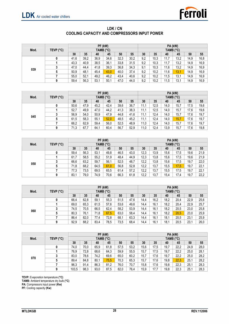
LDK / CN
COOLING CAPACITY AND COMPRESSORS INPUT POWER
PF (kW) PA (kW) TAMB (°C) TAMB (°C) Mod. TEVP (°C)
30 35 40 45 50 55 30 35 40 45 50 55 0 41,6 39,2 36,9 34,6 32,3 30,2 9,2 10,3 11,7 13,2 14,9 16,8 1 43,3 40,9 38,5 36,1 33,8 31,5 9,2 10,3 11,7 13,2 14,9 16,9 3 47,0 44,4 41,8 39,3 36,8 34,3 9,1 10,3 11,6 13,2 14,9 16,9 5 50,9 48,1 45,4 43,0 40,0 37,4 9,2 10,2 11,6 13,1 14,9 16,9 7 55,0 52,1 49,2 46,2 43,4 40,6 9,2 10,2 11,5 13,1 14,9 16,9
039
9 59,4 56,3 53,1 50,1 47,0 44,0 9,2 10,2 11,5 13,1 14,9 16,9
PF (kW) PA (kW) TAMB (°C) TAMB (°C) Mod. TEVP (°C)
30 35 40 45 50 55 30 35 40 45 50 55 0 50,6 47,9 45,2 42,4 39,6 36,7 11,1 12,5 14,0 15,7 17,5 19,6 1 52,7 49,9 47,0 44,2 41,3 38,3 11,1 12,5 14,0 15,7 17,6 19,6 3 56,9 54,0 50,9 47,9 44,8 41,6 11,1 12,4 14,0 15,7 17,6 19,7 5 61,5 58,3 55,1 52,0 48,5 45,2 11,1 12,4 14,0 15,7 17,6 19,7 7 66,2 62,9 59,4 56,0 52,5 48,9 11,0 12,4 14,0 15,7 17,6 19,7
045
9 71,3 67,7 64,1 60,4 56,7 52,9 11,0 12,4 13,9 15,7 17,6 19,8
PF (kW) PA (kW) TAMB (°C) TAMB (°C) Mod. TEVP (°C)
30 35 40 45 50 55 30 35 40 45 50 55 0 59,4 56,3 53,1 49,8 46,5 43,0 12,3 13,9 15,6 17,5 19,6 21,9 1 61,7 58,5 55,2 51,9 48,4 44,9 12,3 13,8 15,6 17,5 19,6 21,9 3 66,6 63,2 59,7 56,1 52,5 48,7 12,2 13,8 15,6 17,5 19,7 22,0 5 71,8 68,2 64,5 61,0 56,8 52,8 12,2 13,7 15,5 17,5 19,7 22,1 7 77,3 73,5 69,5 65,5 61,4 57,2 12,2 13,7 15,5 17,5 19,7 22,1
050
9 83,1 79,0 74,9 70,6 66,3 61,8 12,2 13,7 15,4 17,4 19,7 22,2
PF (kW) PA (kW) TAMB (°C) TAMB (°C) Mod. TEVP (°C)
30 35 40 45 50 55 30 35 40 45 50 55 0 66,4 62,8 59,1 55,3 51,5 47,6 14,4 16,2 18,2 20,4 22,9 25,6 1 69,0 65,3 61,5 57,6 53,6 49,6 14,4 16,1 18,2 20,4 22,9 25,7 3 74,5 70,5 66,5 62,4 58,2 53,9 14,4 16,1 18,2 20,5 23,0 25,8 5 80,3 76,1 71,8 67,5 63,0 58,4 14,4 16,1 18,2 20,5 23,0 25,9 7 86,4 82,0 77,4 72,8 68,1 63,3 14,4 16,1 18,1 20,5 23,1 25,9
060
9 92,9 88,2 83,4 78,5 73,5 68,4 14,4 16,1 18,1 20,5 23,1 26,0
PF (kW) PA (kW) TAMB (°C) TAMB (°C) Mod. TEVP (°C)
30 35 40 45 50 55 30 35 40 45 50 55 0 74,0 70,0 65,9 61,8 57,5 53,2 15,6 17,5 19,7 22,2 24,9 28,0 1 76,9 72,8 68,6 64,3 59,9 55,5 15,7 17,5 19,7 22,2 25,0 28,1 3 83,0 78,6 74,2 69,6 65,0 60,2 15,7 17,6 19,7 22,2 25,0 28,2 5 89,4 84,8 80,1 75,5 70,3 65,3 15,7 17,6 19,8 22,3 25,1 28,2 7 96,3 91,4 86,3 81,2 76,0 70,7 15,8 17,6 19,8 22,3 25,1 28,3
070
9 103,5 98,3 93,0 87,5 82,0 76,4 15,9 17,7 19,8 22,3 25,1 28,3 TEVP: Evaporation temperature (°C) TAMB: Ambient temperature dry bulb (°C) PA: Compressors input power (Kw) PF: Cooling capacity (Kw)
LDK Air cooled water chillers
MTLDKGB REV.112006 29
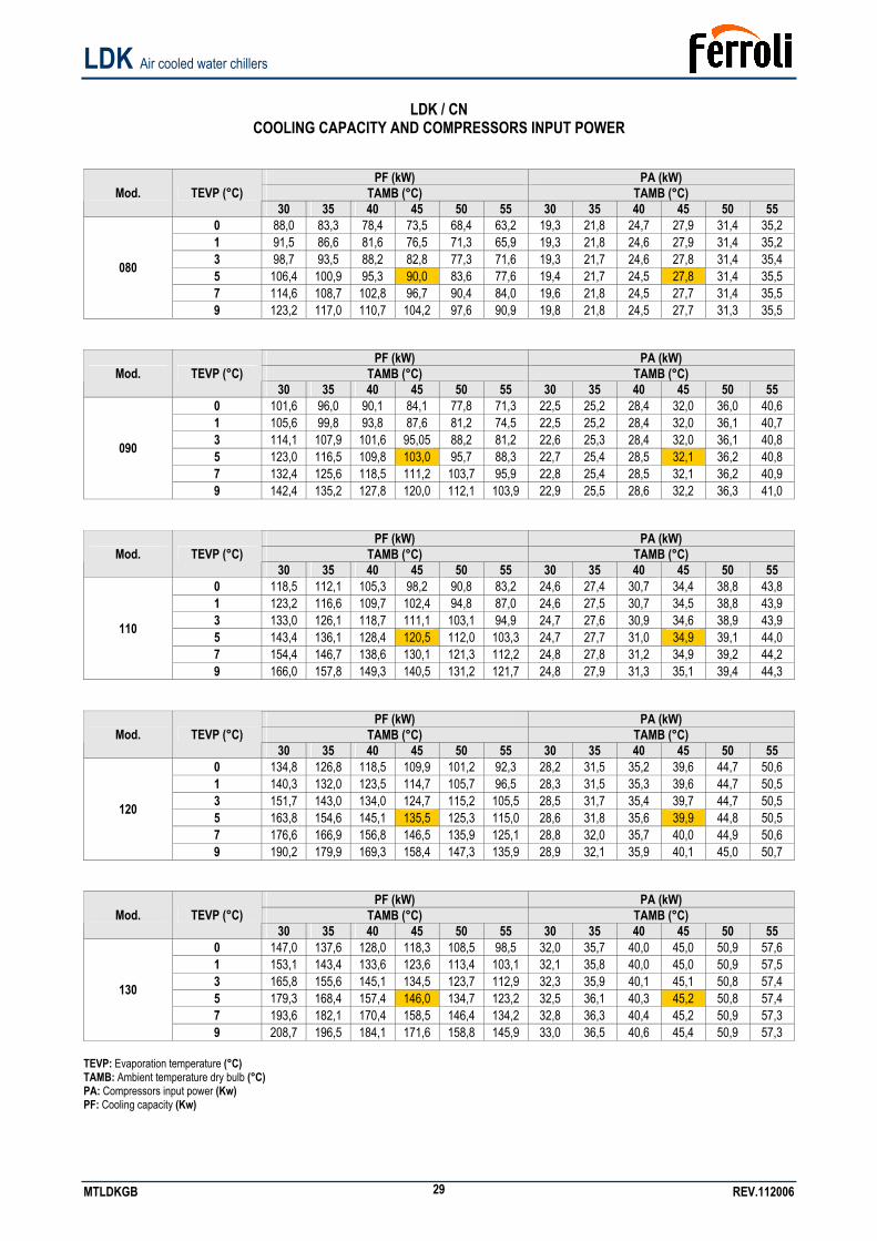
LDK / CN
COOLING CAPACITY AND COMPRESSORS INPUT POWER
PF (kW) PA (kW) TAMB (°C) TAMB (°C) Mod. TEVP (°C)
30 35 40 45 50 55 30 35 40 45 50 55 0 88,0 83,3 78,4 73,5 68,4 63,2 19,3 21,8 24,7 27,9 31,4 35,2 1 91,5 86,6 81,6 76,5 71,3 65,9 19,3 21,8 24,6 27,9 31,4 35,2 3 98,7 93,5 88,2 82,8 77,3 71,6 19,3 21,7 24,6 27,8 31,4 35,4 5 106,4 100,9 95,3 90,0 83,6 77,6 19,4 21,7 24,5 27,8 31,4 35,5 7 114,6 108,7 102,8 96,7 90,4 84,0 19,6 21,8 24,5 27,7 31,4 35,5
080
9 123,2 117,0 110,7 104,2 97,6 90,9 19,8 21,8 24,5 27,7 31,3 35,5
PF (kW) PA (kW) TAMB (°C) TAMB (°C) Mod. TEVP (°C)
30 35 40 45 50 55 30 35 40 45 50 55 0 101,6 96,0 90,1 84,1 77,8 71,3 22,5 25,2 28,4 32,0 36,0 40,6 1 105,6 99,8 93,8 87,6 81,2 74,5 22,5 25,2 28,4 32,0 36,1 40,7 3 114,1 107,9 101,6 95,05 88,2 81,2 22,6 25,3 28,4 32,0 36,1 40,8 5 123,0 116,5 109,8 103,0 95,7 88,3 22,7 25,4 28,5 32,1 36,2 40,8 7 132,4 125,6 118,5 111,2 103,7 95,9 22,8 25,4 28,5 32,1 36,2 40,9
090
9 142,4 135,2 127,8 120,0 112,1 103,9 22,9 25,5 28,6 32,2 36,3 41,0
PF (kW) PA (kW) TAMB (°C) TAMB (°C) Mod. TEVP (°C)
30 35 40 45 50 55 30 35 40 45 50 55 0 118,5 112,1 105,3 98,2 90,8 83,2 24,6 27,4 30,7 34,4 38,8 43,8 1 123,2 116,6 109,7 102,4 94,8 87,0 24,6 27,5 30,7 34,5 38,8 43,9 3 133,0 126,1 118,7 111,1 103,1 94,9 24,7 27,6 30,9 34,6 38,9 43,9 5 143,4 136,1 128,4 120,5 112,0 103,3 24,7 27,7 31,0 34,9 39,1 44,0 7 154,4 146,7 138,6 130,1 121,3 112,2 24,8 27,8 31,2 34,9 39,2 44,2
110
9 166,0 157,8 149,3 140,5 131,2 121,7 24,8 27,9 31,3 35,1 39,4 44,3
PF (kW) PA (kW) TAMB (°C) TAMB (°C) Mod. TEVP (°C)
30 35 40 45 50 55 30 35 40 45 50 55 0 134,8 126,8 118,5 109,9 101,2 92,3 28,2 31,5 35,2 39,6 44,7 50,6 1 140,3 132,0 123,5 114,7 105,7 96,5 28,3 31,5 35,3 39,6 44,7 50,5 3 151,7 143,0 134,0 124,7 115,2 105,5 28,5 31,7 35,4 39,7 44,7 50,5 5 163,8 154,6 145,1 135,5 125,3 115,0 28,6 31,8 35,6 39,9 44,8 50,5 7 176,6 166,9 156,8 146,5 135,9 125,1 28,8 32,0 35,7 40,0 44,9 50,6
120
9 190,2 179,9 169,3 158,4 147,3 135,9 28,9 32,1 35,9 40,1 45,0 50,7
PF (kW) PA (kW) TAMB (°C) TAMB (°C) Mod. TEVP (°C)
30 35 40 45 50 55 30 35 40 45 50 55 0 147,0 137,6 128,0 118,3 108,5 98,5 32,0 35,7 40,0 45,0 50,9 57,6 1 153,1 143,4 133,6 123,6 113,4 103,1 32,1 35,8 40,0 45,0 50,9 57,5 3 165,8 155,6 145,1 134,5 123,7 112,9 32,3 35,9 40,1 45,1 50,8 57,4 5 179,3 168,4 157,4 146,0 134,7 123,2 32,5 36,1 40,3 45,2 50,8 57,4 7 193,6 182,1 170,4 158,5 146,4 134,2 32,8 36,3 40,4 45,2 50,9 57,3
130
9 208,7 196,5 184,1 171,6 158,8 145,9 33,0 36,5 40,6 45,4 50,9 57,3 TEVP: Evaporation temperature (°C) TAMB: Ambient temperature dry bulb (°C) PA: Compressors input power (Kw) PF: Cooling capacity (Kw)
LDK Air cooled water chillers
MTLDKGB REV.112006 30
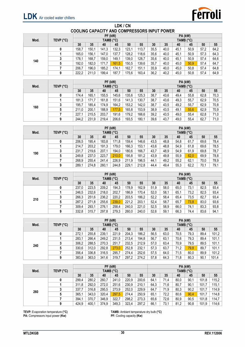
LDK / CN COOLING CAPACITY AND COMPRESSORS INPUT POWER
PF (kW) PA (kW) TAMB (°C) TAMB (°C) Mod. TEVP (°C)
30 35 40 45 50 55 30 35 40 45 50 55 0 158,7 150,1 141,3 132,3 123,1 113,7 35,5 40,0 45,1 50,9 57,2 64,2 1 165,0 156,1 147,0 137,7 128,2 118,6 35,6 40,0 45,1 50,9 57,3 64,3 3 178,1 168,7 159,0 149,1 139,0 128,7 35,6 40,0 45,1 50,9 57,4 64,6 5 192,0 182,0 171,7 161,5 150,5 139,6 35,7 40,0 45,0 50,9 57,4 64,7 7 206,7 196,0 185,2 174,1 162,7 151,1 35,9 40,0 45,0 50,8 57,4 64,8
140
9 222,2 211,0 199,4 187,7 175,6 163,4 36,2 40,2 45,0 50,8 57,4 64,9
PF (kW) PA (kW) TAMB (°C) TAMB (°C) Mod. TEVP (°C)
30 35 40 45 50 55 30 35 40 45 50 55 0 174,4 165,1 155,5 145,6 135,6 125,3 38,7 43,6 49,4 55,8 62,8 70,3 1 181,3 171,7 161,8 151,6 141,3 130,7 38,7 43,6 49,3 55,7 62,9 70,5 3 195,7 185,4 174,9 164,2 153,2 142,0 38,7 43,5 49,2 55,7 62,9 70,8 5 211,0 200,1 188,9 177,5 165,8 153,9 38,9 43,5 49,1 55,6 62,9 70,9 7 227,1 215,5 203,7 191,6 179,2 166,6 39,2 43,5 49,0 55,4 62,8 71,0
160
9 244,2 231,9 219,4 206,6 193,5 180,1 39,6 43,7 49,0 55,4 62,7 71,0
PF (kW) PA (kW) TAMB (°C) TAMB (°C) Mod. TEVP (°C)
30 35 40 45 50 55 30 35 40 45 50 55 0 206,5 195,4 183,8 171,8 159,4 146,6 43,5 48,8 54,8 61,7 69,6 78,4 1 214,7 203,2 191,3 179,0 166,3 153,1 43,6 48,8 54,9 61,8 69,6 78,5 3 231,7 219,6 207,1 194,0 180,6 166,7 43,7 48,9 54,9 61,9 69,8 78,7 5 249,8 237,0 223,7 210,0 195,8 181,2 43,9 49,8 55,9 62,0 69,9 78,8 7 268,9 255,4 241,4 226,9 211,9 196,5 44,1 49,2 55,2 62,1 70,0 78,9
190
9 289,1 274,8 260,1 244,8 229,1 212,8 44,4 49,4 55,3 62,2 70,1 79,1
PF (kW) PA (kW) TAMB (°C) TAMB (°C) Mod. TEVP (°C)
30 35 40 45 50 55 30 35 40 45 50 55 0 237,0 223,5 209,2 194,3 178,9 162,9 51,9 58,0 65,0 73,1 82,5 93,4 1 246,5 232,6 218,0 202,7 186,9 170,4 52,0 58,1 65,1 73,2 82,5 93,4 3 266,3 251,6 236,2 220,2 203,5 186,2 52,2 58,4 65,4 73,5 82,7 93,4 5 287,2 271,8 255,6 239,0 221,2 203,1 52,4 58,7 65,7 73,8 83,0 93,6 7 309,4 293,1 276,1 258,4 240,0 221,0 52,5 58,9 66,0 74,1 83,3 93,8
210
9 332,8 315,7 297,8 279,3 260,0 240,0 52,6 59,1 66,3 74,4 83,6 94,1
PF (kW) PA (kW) TAMB (°C) TAMB (°C) Mod. TEVP (°C)
30 35 40 45 50 55 30 35 40 45 50 55 0 272,1 255,8 239,1 221,9 204,3 186,2 56,5 63,0 70,5 79,3 89,4 101,2 1 283,1 266,4 249,2 231,5 213,4 194,8 56,7 63,1 70,6 79,3 89,4 101,1 3 306,2 288,5 270,3 251,7 232,5 212,9 57,0 63,4 70,9 79,5 89,5 101,1 5 330,6 312,0 292,8 273,0 252,8 232,1 57,3 63,7 71,2 79,8 89,7 101,1 7 356,4 336,8 316,5 295,7 274,4 252,6 57,5 64,0 71,5 80,0 89,9 101,2
240
9 383,8 363,0 341,6 319,7 297,2 274,2 57,8 64,3 71,8 80,3 90,1 101,4
PF (kW) PA (kW) TAMB (°C) TAMB (°C) Mod. TEVP (°C)
30 35 40 45 50 55 30 35 40 45 50 55 0 299,4 280,2 260,7 241,0 220,9 200,6 64,1 71,4 80,0 90,1 101,8 115,2 1 311,8 292,0 272,0 251,6 230,9 210,1 64,3 71,6 80,7 90,1 101,7 115,1 3 337,7 316,8 295,5 273,9 252,0 229,9 64,7 71,9 80,3 90,2 101,7 114,9 5 365,1 343,0 320,4 297,5 274,4 250,9 65,1 72,2 80,6 90,4 101,7 114,8 7 394,1 370,7 346,9 322,7 298,2 273,3 65,6 72,6 80,9 90,5 101,8 114,7
260
9 424,9 400,1 374,9 349,3 323,4 297,2 66,1 73,1 81,2 90,8 101,9 114,6 TEVP: Evaporation temperature (°C) TAMB: Ambient temperature dry bulb (°C) PA: Compressors input power (Kw) PF: Cooling capacity (Kw)
LDK Air cooled water chillers
MTLDKGB REV.112006 31
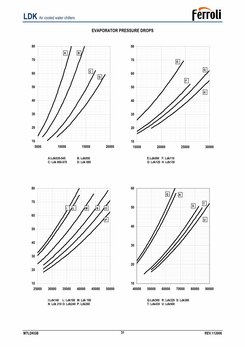
EVAPORATOR PRESSURE DROPS
10
20
30
40
50
60
70
80
5000 10000 15000 20000
10
20
30
40
50
60
70
80
15000 20000 25000 30000
A:Ldk039-045 B: Ldk050 C: Ldk 060-070 D: Ldk 080
E:Ldk090 F: Ldk110 G: Ldk120 H: Ldk130
10
20
30
40
50
60
70
80
25000 30000 35000 40000 45000 50000
10
20
30
40
50
60
40000 50000 60000 70000 80000 90000
I:Ldk140 L: Ldk160 M: Ldk 190 N: Ldk 210 O: Ldk240 P: Ldk260
Q:Ldk300 R: Ldk320 S: Ldk380 T: Ldk430 U: Ldk500
I L M N O
P
E
D C
B A
F
G
H
Q R
S T
U
LDK Air cooled water chillers
MTLDKGB REV.112006 32
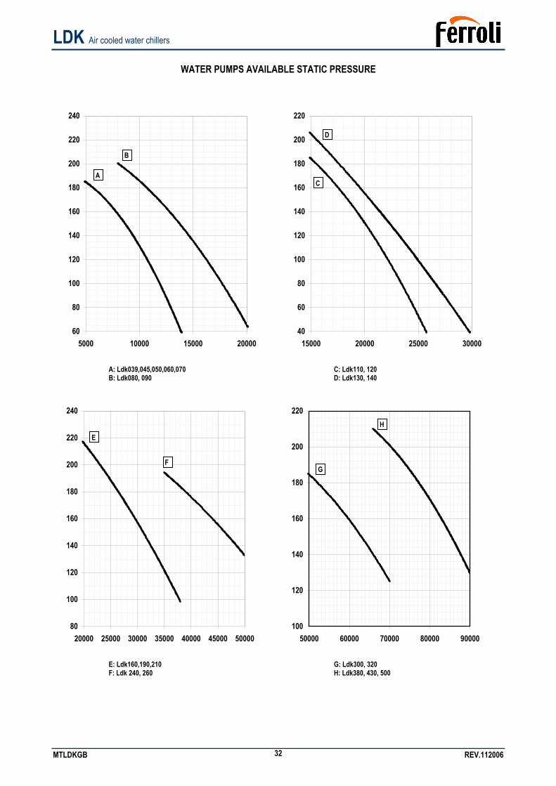
WATER PUMPS AVAILABLE STATIC PRESSURE
60
80
100
120
140
160
180
200
220
240
5000 10000 15000 20000
40
60
80
100
120
140
160
180
200
220
15000 20000 25000 30000
A: Ldk039,045,050,060,070 B: Ldk080, 090
C: Ldk110, 120 D: Ldk130, 140
80
100
120
140
160
180
200
220
240
20000 25000 30000 35000 40000 45000 50000
100
120
140
160
180
200
220
50000 60000 70000 80000 90000
E: Ldk160,190,210 F: Ldk 240, 260
G: Ldk300, 320 H: Ldk380, 430, 500
B
AC
D
H
F
E
G
LDK Air cooled water chillers
MTLDKGB REV.112006 33
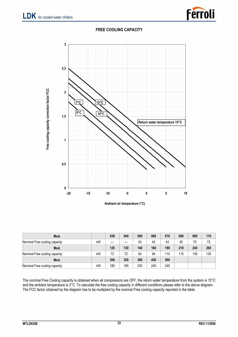
FREE COOLING CAPACITY
Free
cool
ing
capa
city c
orre
ctio
n fa
ctor
FCC
0
0,5
1
1,5
2
2,5
3
-20 -15 -10 -5 0 5 10
Ambient air temperature (°C)
Mod. 039 045 050 060 070 080 090 110 Nominal Free cooling capacity kW --- --- 43 43 43 45 70 72
Mod. 120 130 140 160 190 210 240 260 Nominal Free cooling capacity kW 72 72 94 94 110 115 135 135
Mod. 300 320 380 430 500 Nominal Free cooling capacity kW 185 185 235 245 240 The nominal Free Cooling capacity is obtained when all compressors are OFF, the return water temperature from the system is 15°C and the ambient temperature is 2°C. To calculate the free cooling capacity in different conditions please refer to the above diagram. The FCC factor obtained by the diagram has to be multiplied by the nominal Free cooling capacity reported in the table.
Return water temperature 15°C
12°C
10°C
7°C
5°C
LDK Air cooled water chillers
MTLDKGB REV.112006 34
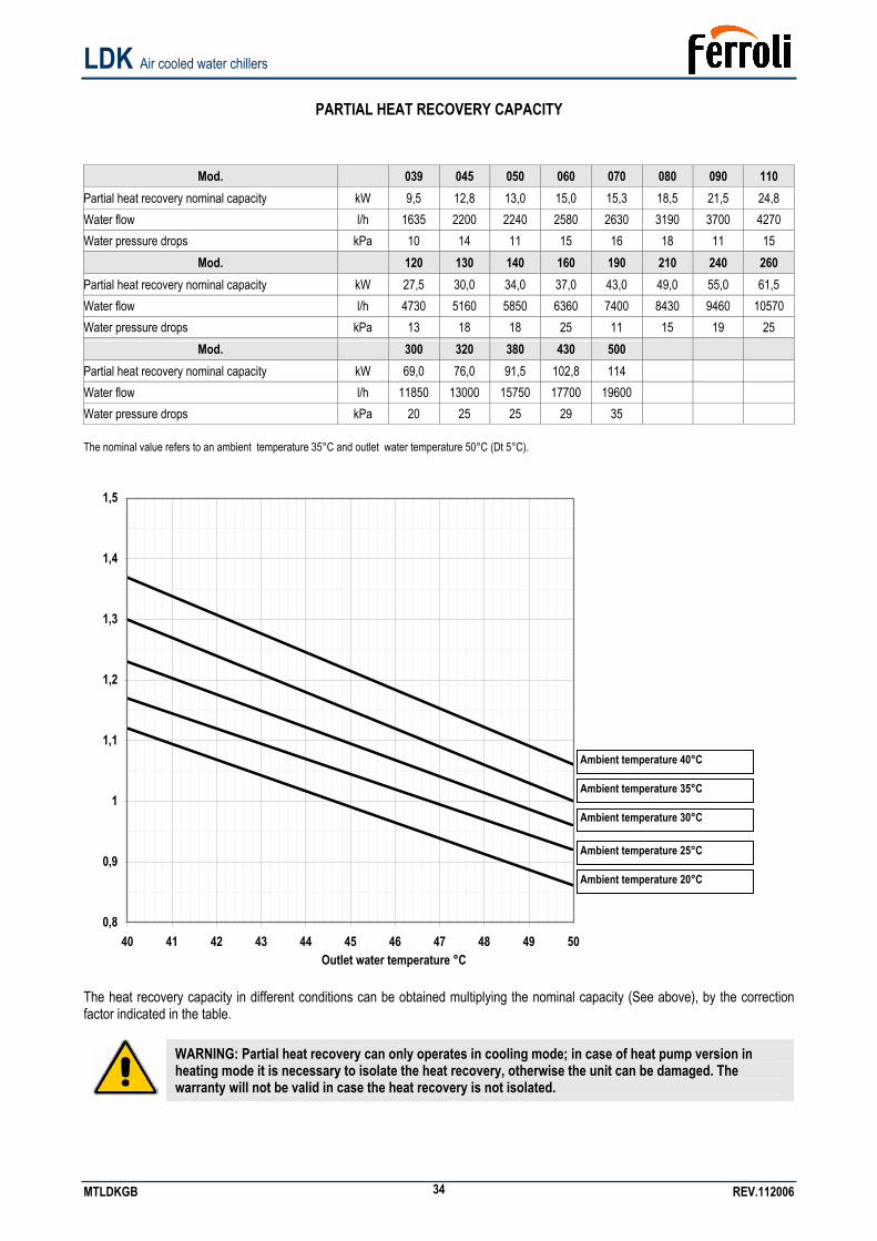
PARTIAL HEAT RECOVERY CAPACITY
Mod. 039 045 050 060 070 080 090 110 Partial heat recovery nominal capacity kW 9,5 12,8 13,0 15,0 15,3 18,5 21,5 24,8 Water flow l/h 1635 2200 2240 2580 2630 3190 3700 4270 Water pressure drops kPa 10 14 11 15 16 18 11 15
Mod. 120 130 140 160 190 210 240 260 Partial heat recovery nominal capacity kW 27,5 30,0 34,0 37,0 43,0 49,0 55,0 61,5 Water flow l/h 4730 5160 5850 6360 7400 8430 9460 10570 Water pressure drops kPa 13 18 18 25 11 15 19 25
Mod. 300 320 380 430 500 Partial heat recovery nominal capacity kW 69,0 76,0 91,5 102,8 114 Water flow l/h 11850 13000 15750 17700 19600 Water pressure drops kPa 20 25 25 29 35 The nominal value refers to an ambient temperature 35°C and outlet water temperature 50°C (Dt 5°C).
0,8
0,9
1
1,1
1,2
1,3
1,4
1,5
40 41 42 43 44 45 46 47 48 49 50
The heat recovery capacity in different conditions can be obtained multiplying the nominal capacity (See above), by the correction factor indicated in the table.
WARNING: Partial heat recovery can only operates in cooling mode; in case of heat pump version in heating mode it is necessary to isolate the heat recovery, otherwise the unit can be damaged. The warranty will not be valid in case the heat recovery is not isolated.
Ambient temperature 35°C
Ambient temperature 30°C
Ambient temperature 25°C
Ambient temperature 40°C
Ambient temperature 20°C
Outlet water temperature °C
LDK Air cooled water chillers
MTLDKGB REV.112006 35
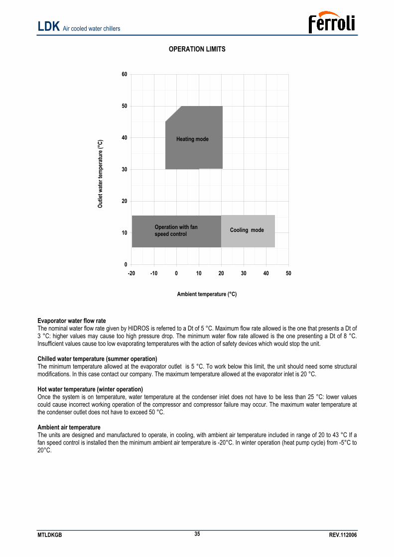
OPERATION LIMITS
Outle
t wat
er te
mpe
ratu
re (°
C)
0
10
20
30
40
50
60
-20 -10 0 10 20 30 40 50
Ambient temperature (°C)
Evaporator water flow rate The nominal water flow rate given by HIDROS is referred to a Dt of 5 °C. Maximum flow rate allowed is the one that presents a Dt of 3 °C: higher values may cause too high pressure drop. The minimum water flow rate allowed is the one presenting a Dt of 8 °C. Insufficient values cause too low evaporating temperatures with the action of safety devices which would stop the unit. Chilled water temperature (summer operation) The minimum temperature allowed at the evaporator outlet is 5 °C. To work below this limit, the unit should need some structural modifications. In this case contact our company. The maximum temperature allowed at the evaporator inlet is 20 °C. Hot water temperature (winter operation) Once the system is on temperature, water temperature at the condenser inlet does not have to be less than 25 °C: lower values could cause incorrect working operation of the compressor and compressor failure may occur. The maximum water temperature at the condenser outlet does not have to exceed 50 °C. Ambient air temperature The units are designed and manufactured to operate, in cooling, with ambient air temperature included in range of 20 to 43 °C If a fan speed control is installed then the minimum ambient air temperature is -20°C. In winter operation (heat pump cycle) from -5°C to 20°C.
Operation with fan speed control
Heating mode
Cooling mode
LDK Air cooled water chillers
MTLDKGB REV.112006 36
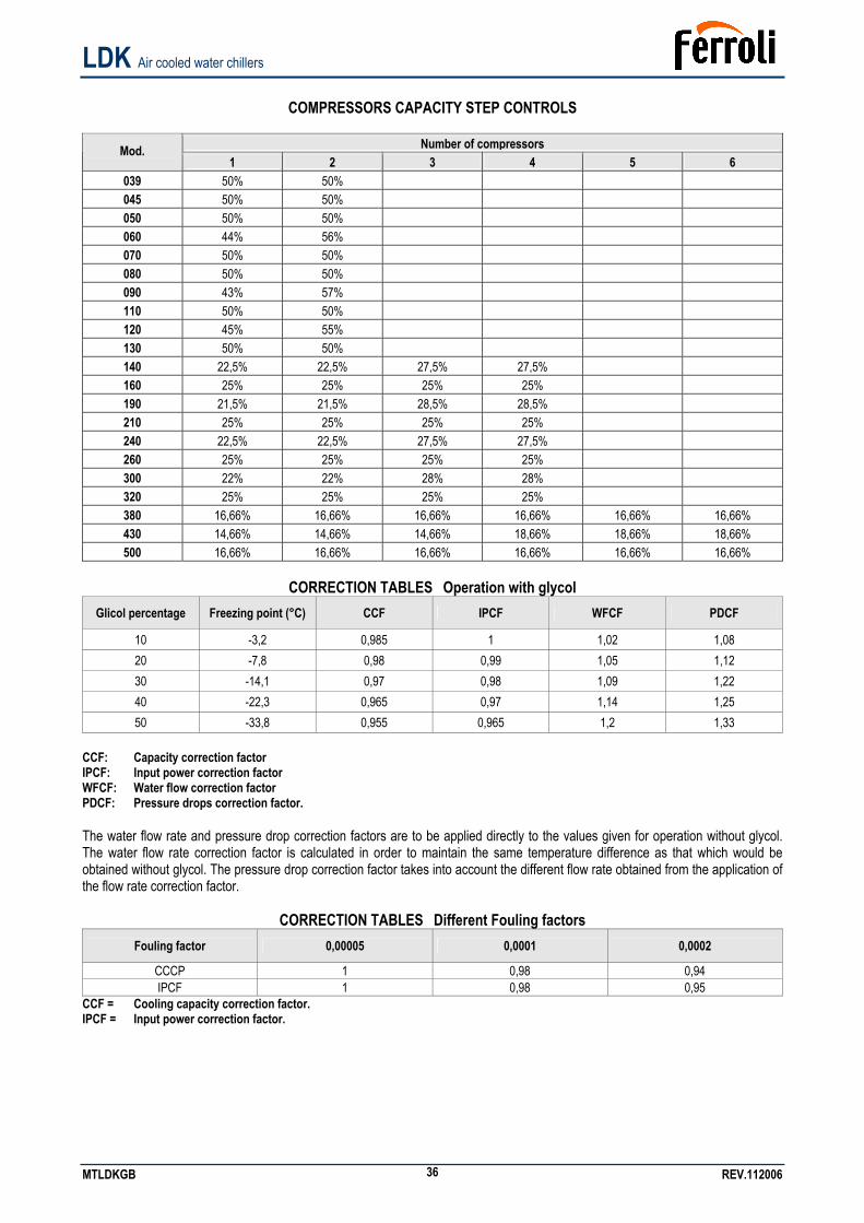
COMPRESSORS CAPACITY STEP CONTROLS
Number of compressors Mod.
1 2 3 4 5 6 039 50% 50% 045 50% 50% 050 50% 50% 060 44% 56% 070 50% 50% 080 50% 50% 090 43% 57% 110 50% 50% 120 45% 55% 130 50% 50% 140 22,5% 22,5% 27,5% 27,5% 160 25% 25% 25% 25% 190 21,5% 21,5% 28,5% 28,5% 210 25% 25% 25% 25% 240 22,5% 22,5% 27,5% 27,5% 260 25% 25% 25% 25% 300 22% 22% 28% 28% 320 25% 25% 25% 25% 380 16,66% 16,66% 16,66% 16,66% 16,66% 16,66% 430 14,66% 14,66% 14,66% 18,66% 18,66% 18,66% 500 16,66% 16,66% 16,66% 16,66% 16,66% 16,66%
CORRECTION TABLES Operation with glycol
Glicol percentage Freezing point (°C) CCF IPCF WFCF PDCF
10 -3,2 0,985 1 1,02 1,08 20 -7,8 0,98 0,99 1,05 1,12 30 -14,1 0,97 0,98 1,09 1,22 40 -22,3 0,965 0,97 1,14 1,25 50 -33,8 0,955 0,965 1,2 1,33
CCF: Capacity correction factor IPCF: Input power correction factor WFCF: Water flow correction factor PDCF: Pressure drops correction factor. The water flow rate and pressure drop correction factors are to be applied directly to the values given for operation without glycol. The water flow rate correction factor is calculated in order to maintain the same temperature difference as that which would be obtained without glycol. The pressure drop correction factor takes into account the different flow rate obtained from the application of the flow rate correction factor.
CORRECTION TABLES Different Fouling factors Fouling factor 0,00005 0,0001 0,0002
CCCP 1 0,98 0,94 IPCF 1 0,98 0,95
CCF = Cooling capacity correction factor. IPCF = Input power correction factor.
LDK Air cooled water chillers
MTLDKGB REV.112006 37
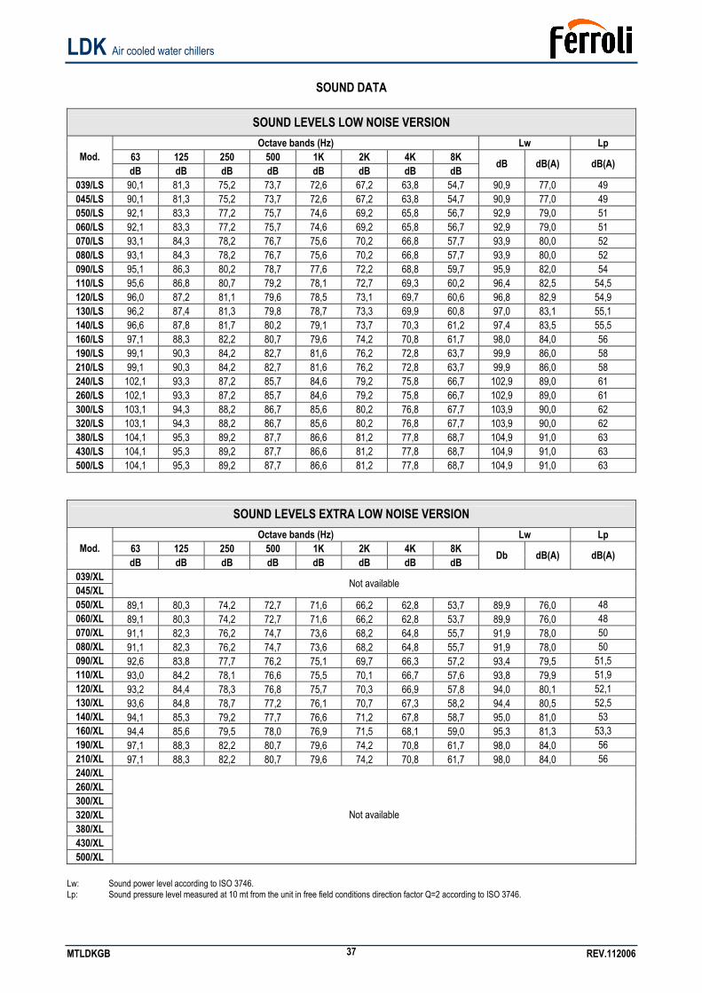
SOUND DATA
SOUND LEVELS LOW NOISE VERSION Octave bands (Hz) Lw Lp
63 125 250 500 1K 2K 4K 8K Mod. dB dB dB dB dB dB dB dB dB dB(A) dB(A)
039/LS 90,1 81,3 75,2 73,7 72,6 67,2 63,8 54,7 90,9 77,0 49 045/LS 90,1 81,3 75,2 73,7 72,6 67,2 63,8 54,7 90,9 77,0 49 050/LS 92,1 83,3 77,2 75,7 74,6 69,2 65,8 56,7 92,9 79,0 51 060/LS 92,1 83,3 77,2 75,7 74,6 69,2 65,8 56,7 92,9 79,0 51 070/LS 93,1 84,3 78,2 76,7 75,6 70,2 66,8 57,7 93,9 80,0 52 080/LS 93,1 84,3 78,2 76,7 75,6 70,2 66,8 57,7 93,9 80,0 52 090/LS 95,1 86,3 80,2 78,7 77,6 72,2 68,8 59,7 95,9 82,0 54 110/LS 95,6 86,8 80,7 79,2 78,1 72,7 69,3 60,2 96,4 82,5 54,5 120/LS 96,0 87,2 81,1 79,6 78,5 73,1 69,7 60,6 96,8 82,9 54,9 130/LS 96,2 87,4 81,3 79,8 78,7 73,3 69,9 60,8 97,0 83,1 55,1 140/LS 96,6 87,8 81,7 80,2 79,1 73,7 70,3 61,2 97,4 83,5 55,5 160/LS 97,1 88,3 82,2 80,7 79,6 74,2 70,8 61,7 98,0 84,0 56 190/LS 99,1 90,3 84,2 82,7 81,6 76,2 72,8 63,7 99,9 86,0 58 210/LS 99,1 90,3 84,2 82,7 81,6 76,2 72,8 63,7 99,9 86,0 58 240/LS 102,1 93,3 87,2 85,7 84,6 79,2 75,8 66,7 102,9 89,0 61 260/LS 102,1 93,3 87,2 85,7 84,6 79,2 75,8 66,7 102,9 89,0 61 300/LS 103,1 94,3 88,2 86,7 85,6 80,2 76,8 67,7 103,9 90,0 62 320/LS 103,1 94,3 88,2 86,7 85,6 80,2 76,8 67,7 103,9 90,0 62 380/LS 104,1 95,3 89,2 87,7 86,6 81,2 77,8 68,7 104,9 91,0 63 430/LS 104,1 95,3 89,2 87,7 86,6 81,2 77,8 68,7 104,9 91,0 63 500/LS 104,1 95,3 89,2 87,7 86,6 81,2 77,8 68,7 104,9 91,0 63
SOUND LEVELS EXTRA LOW NOISE VERSION Octave bands (Hz) Lw Lp
63 125 250 500 1K 2K 4K 8K Mod. dB dB dB dB dB dB dB dB Db dB(A) dB(A)
039/XL 045/XL Not available
050/XL 89,1 80,3 74,2 72,7 71,6 66,2 62,8 53,7 89,9 76,0 48 060/XL 89,1 80,3 74,2 72,7 71,6 66,2 62,8 53,7 89,9 76,0 48 070/XL 91,1 82,3 76,2 74,7 73,6 68,2 64,8 55,7 91,9 78,0 50 080/XL 91,1 82,3 76,2 74,7 73,6 68,2 64,8 55,7 91,9 78,0 50 090/XL 92,6 83,8 77,7 76,2 75,1 69,7 66,3 57,2 93,4 79,5 51,5 110/XL 93,0 84,2 78,1 76,6 75,5 70,1 66,7 57,6 93,8 79,9 51,9 120/XL 93,2 84,4 78,3 76,8 75,7 70,3 66,9 57,8 94,0 80,1 52,1 130/XL 93,6 84,8 78,7 77,2 76,1 70,7 67,3 58,2 94,4 80,5 52,5 140/XL 94,1 85,3 79,2 77,7 76,6 71,2 67,8 58,7 95,0 81,0 53 160/XL 94,4 85,6 79,5 78,0 76,9 71,5 68,1 59,0 95,3 81,3 53,3 190/XL 97,1 88,3 82,2 80,7 79,6 74,2 70,8 61,7 98,0 84,0 56 210/XL 97,1 88,3 82,2 80,7 79,6 74,2 70,8 61,7 98,0 84,0 56 240/XL 260/XL 300/XL 320/XL 380/XL 430/XL 500/XL
Not available
Lw: Sound power level according to ISO 3746. Lp: Sound pressure level measured at 10 mt from the unit in free field conditions direction factor Q=2 according to ISO 3746.
LDK Air cooled water chillers
MTLDKGB REV.112006 38
SAFETY DEVICE SETTING
Capacity Steps Capacity steps 2 4 Device Set-point Differential Set point Differential
Reset Type
Control thermostat (summer) °C 10 2 9 3 … Control thermostat (winter) °C 42 2 43 3 … Anti-freeze thermostat °C 4 6 4 6 MANUAL Electric heater thermostat °C 4 6 4 6 MANUAL High pressure switch Bar 28 7 28 7 MANUAL Low pressure switch Bar 0,7 1 0,7 1 MANUAL Water safety valve (Optional) Bar 6 … 6 … …
ELECTRIC DATA
Power supply V/~/Hz 400 / 3 / 50 Control board V/~/Hz 24 / 1 / 50 Auxiliary circuit V/~/Hz 230 / 1 / 50 Fans power supply V/~/Hz 400 / 3 / 50
Electric data may change for updating. It is therefore necessary to refer always to the wiring diagram inside the units.
WARNING: All this operation described in next chapters MUST BE DONE BY TRAINED PEOPLE ONLY. Before every operation of servicing on the unit, be sure that the electric supply is disconnected.
INSPECTION When installing or servicing the unit, it is necessary to strictly follow the rules reported on this manual, to conform to all the specifications of the labels on the unit, and to take any possible precautions of the case. Not observing the rules reported on this manual can create dangerous situations. After receiving the unit, immediately check its integrity. The unit left the factory in perfect condition; any eventual damage must be questioned to the carrier and recorded on the Delivery Note before it is signed. HIDROS must be informed, within 8 days, of the extent of the damage. The Customer should prepare a written statement of any severe damage.
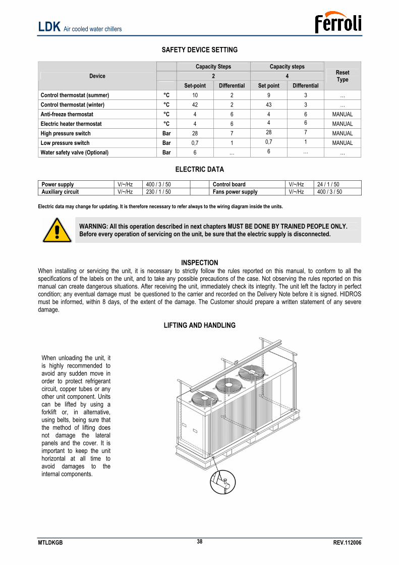
LIFTING AND HANDLING
When unloading the unit, it is highly recommended to avoid any sudden move in order to protect refrigerant circuit, copper tubes or any other unit component. Units can be lifted by using a forklift or, in alternative, using belts, being sure that the method of lifting does not damage the lateral panels and the cover. It is important to keep the unit horizontal at all time to avoid damages to the internal components.
LDK Air cooled water chillers
MTLDKGB REV.112006 39
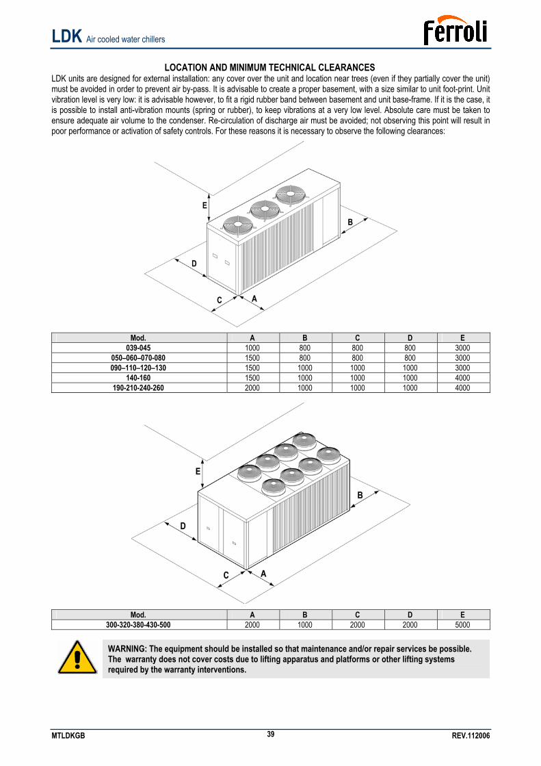
LOCATION AND MINIMUM TECHNICAL CLEARANCES
LDK units are designed for external installation: any cover over the unit and location near trees (even if they partially cover the unit) must be avoided in order to prevent air by-pass. It is advisable to create a proper basement, with a size similar to unit foot-print. Unit vibration level is very low: it is advisable however, to fit a rigid rubber band between basement and unit base-frame. If it is the case, it is possible to install anti-vibration mounts (spring or rubber), to keep vibrations at a very low level. Absolute care must be taken to ensure adequate air volume to the condenser. Re-circulation of discharge air must be avoided; not observing this point will result in poor performance or activation of safety controls. For these reasons it is necessary to observe the following clearances:
Mod. A B C D E
039-045 1000 800 800 800 3000 050–060–070-080 1500 800 800 800 3000 090–110–120–130 1500 1000 1000 1000 3000
140-160 1500 1000 1000 1000 4000 190-210-240-260 2000 1000 1000 1000 4000
Mod. A B C D E
300-320-380-430-500 2000 1000 2000 2000 5000
WARNING: The equipment should be installed so that maintenance and/or repair services be possible. The warranty does not cover costs due to lifting apparatus and platforms or other lifting systems required by the warranty interventions.
LDK Air cooled water chillers
MTLDKGB REV.112006 40
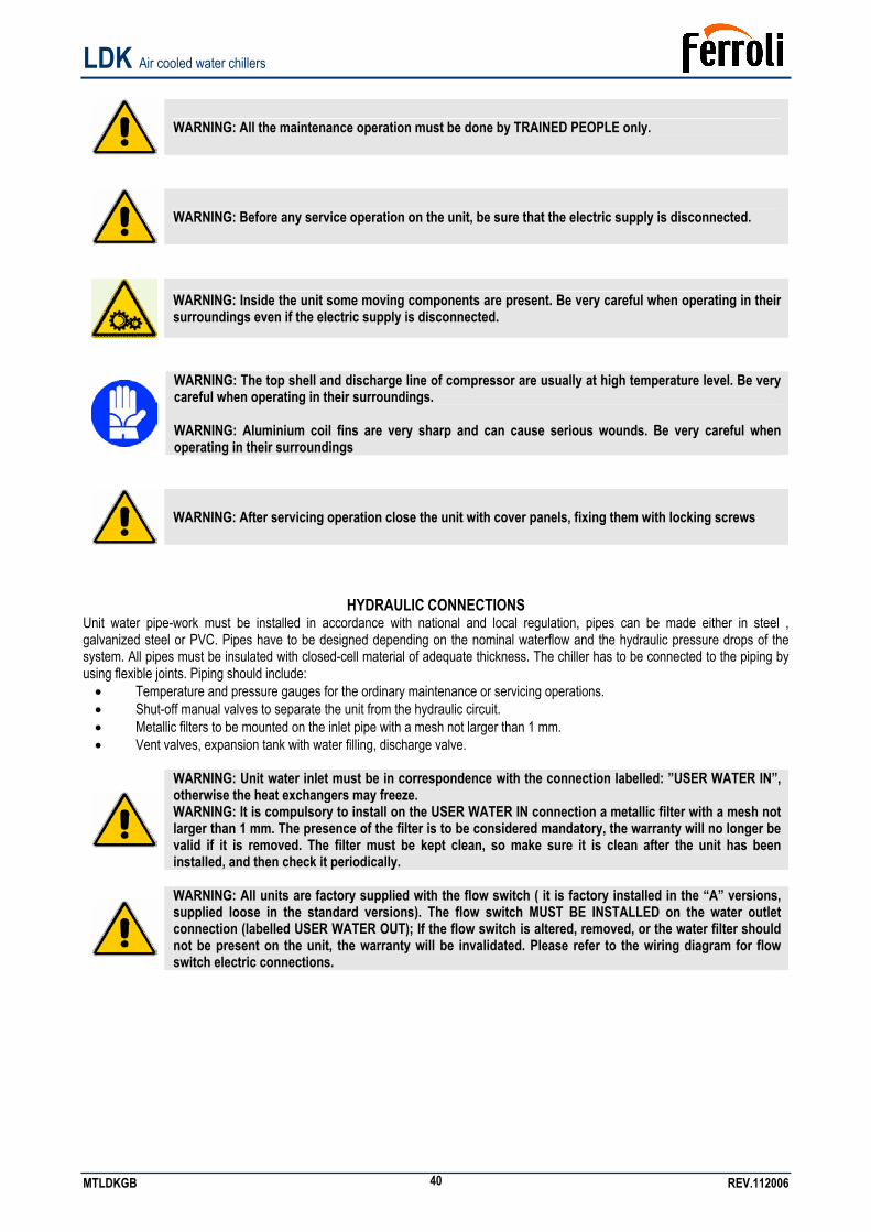
WARNING: All the maintenance operation must be done by TRAINED PEOPLE only.
WARNING: Before any service operation on the unit, be sure that the electric supply is disconnected.
WARNING: Inside the unit some moving components are present. Be very careful when operating in their surroundings even if the electric supply is disconnected.
WARNING: The top shell and discharge line of compressor are usually at high temperature level. Be very careful when operating in their surroundings.
WARNING: Aluminium coil fins are very sharp and can cause serious wounds. Be very careful when operating in their surroundings
WARNING: After servicing operation close the unit with cover panels, fixing them with locking screws
HYDRAULIC CONNECTIONS Unit water pipe-work must be installed in accordance with national and local regulation, pipes can be made either in steel , galvanized steel or PVC. Pipes have to be designed depending on the nominal waterflow and the hydraulic pressure drops of the system. All pipes must be insulated with closed-cell material of adequate thickness. The chiller has to be connected to the piping by using flexible joints. Piping should include: • Temperature and pressure gauges for the ordinary maintenance or servicing operations. • Shut-off manual valves to separate the unit from the hydraulic circuit. • Metallic filters to be mounted on the inlet pipe with a mesh not larger than 1 mm. • Vent valves, expansion tank with water filling, discharge valve.
WARNING: Unit water inlet must be in correspondence with the connection labelled: ”USER WATER IN”, otherwise the heat exchangers may freeze. WARNING: It is compulsory to install on the USER WATER IN connection a metallic filter with a mesh not larger than 1 mm. The presence of the filter is to be considered mandatory, the warranty will no longer be valid if it is removed. The filter must be kept clean, so make sure it is clean after the unit has been installed, and then check it periodically.
WARNING: All units are factory supplied with the flow switch ( it is factory installed in the “A” versions, supplied loose in the standard versions). The flow switch MUST BE INSTALLED on the water outlet connection (labelled USER WATER OUT); If the flow switch is altered, removed, or the water filter should not be present on the unit, the warranty will be invalidated. Please refer to the wiring diagram for flow switch electric connections.
LDK Air cooled water chillers
MTLDKGB REV.112006 41
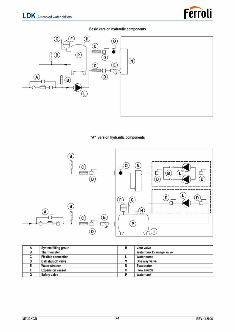
Basic version hydraulic components
“A” version hydraulic components
A System filling group H Vent valve B Thermometer I Water tank Drainage valve C Flexible connection L Water pump D Ball shut-off valve M One way valve E Water strainer N Evaporator F Expansion vessel O Flow switch G Safety valve P Water tank
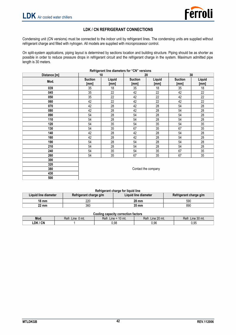
LDK Air cooled water chillers
MTLDKGB REV.112006 42
LDK / CN REFRIGERANT CONNECTIONS
Condensing unit (CN versions) must be connected to the indoor unit by refrigerant lines. The condensing units are supplied without refrigerant charge and filled with nytrogen. All models are supplied with microprocessor control. On split-system applications, piping layout is determined by sections location and building structure. Piping should be as shorter as possible in order to reduce pressure drops in refrigerant circuit and the refrigerant charge in the system. Maximum admitted pipe length is 30 meters.
Refrigerant line diameters for “CN” versions Distance [m] 10 20 30
Mod. Suction [mm]
Liquid [mm]
Suction [mm]
Liquid [mm]
Suction [mm]
Liquid [mm]
039 35 18 35 18 35 18 045 35 22 42 22 42 22 050 35 22 42 22 42 22 060 42 22 42 22 42 22 070 42 28 42 28 54 28 080 42 28 42 28 54 28 090 54 28 54 28 54 28 110 54 28 54 28 54 28 120 54 35 54 35 54 35 130 54 35 67 35 67 35 140 42 28 42 28 54 28 160 42 28 42 28 54 28 190 54 28 54 28 54 28 210 54 28 54 28 54 28 240 54 35 54 35 67 35 260 54 35 67 35 67 35 300 320 380 430 500
Contact the company
Refrigerant charge for liquid line Liquid line diameter Refrigerant charge g/m Liquid line diameter Refrigerant charge g/m
18 mm 220 28 mm 590 22 mm 360 35 mm 890
Cooling capacity correction factors
Mod. Refr. Line 0 mt. Refr. Line = 10 mt. Refr. Line 20 mt. Refr. Line 30 mt. LDK / CN 1 0,98 0,96 0,95
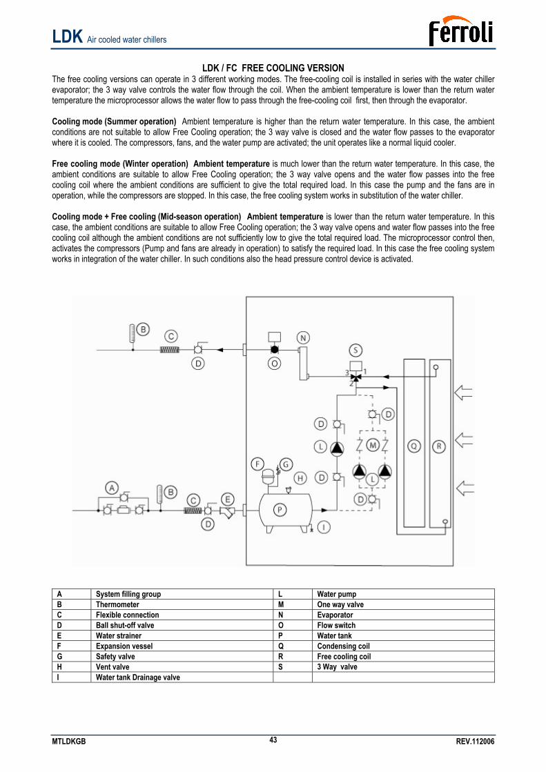
LDK Air cooled water chillers
MTLDKGB REV.112006 43
LDK / FC FREE COOLING VERSION
The free cooling versions can operate in 3 different working modes. The free-cooling coil is installed in series with the water chiller evaporator; the 3 way valve controls the water flow through the coil. When the ambient temperature is lower than the return water temperature the microprocessor allows the water flow to pass through the free-cooling coil first, then through the evaporator. Cooling mode (Summer operation) Ambient temperature is higher than the return water temperature. In this case, the ambient conditions are not suitable to allow Free Cooling operation; the 3 way valve is closed and the water flow passes to the evaporator where it is cooled. The compressors, fans, and the water pump are activated; the unit operates like a normal liquid cooler. Free cooling mode (Winter operation) Ambient temperature is much lower than the return water temperature. In this case, the ambient conditions are suitable to allow Free Cooling operation; the 3 way valve opens and the water flow passes into the free cooling coil where the ambient conditions are sufficient to give the total required load. In this case the pump and the fans are in operation, while the compressors are stopped. In this case, the free cooling system works in substitution of the water chiller. Cooling mode + Free cooling (Mid-season operation) Ambient temperature is lower than the return water temperature. In this case, the ambient conditions are suitable to allow Free Cooling operation; the 3 way valve opens and water flow passes into the free cooling coil although the ambient conditions are not sufficiently low to give the total required load. The microprocessor control then, activates the compressors (Pump and fans are already in operation) to satisfy the required load. In this case the free cooling system works in integration of the water chiller. In such conditions also the head pressure control device is activated.
A System filling group L Water pump B Thermometer M One way valve C Flexible connection N Evaporator D Ball shut-off valve O Flow switch E Water strainer P Water tank F Expansion vessel Q Condensing coil G Safety valve R Free cooling coil H Vent valve S 3 Way valve I Water tank Drainage valve
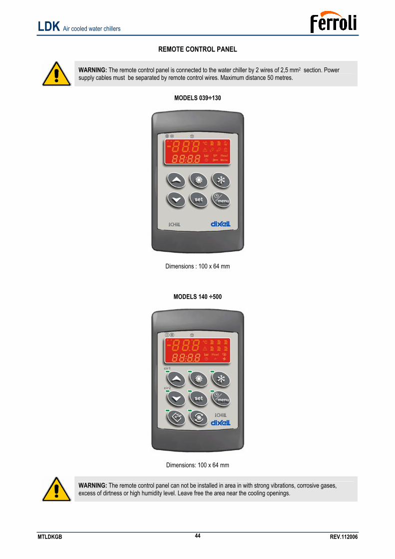
LDK Air cooled water chillers
MTLDKGB REV.112006 44
REMOTE CONTROL PANEL
WARNING: The remote control panel is connected to the water chiller by 2 wires of 2,5 mm2 section. Power supply cables must be separated by remote control wires. Maximum distance 50 metres.
MODELS 039÷130
Dimensions : 100 x 64 mm
MODELS 140 ÷500
Dimensions: 100 x 64 mm
WARNING: The remote control panel can not be installed in area in with strong vibrations, corrosive gases, excess of dirtness or high humidity level. Leave free the area near the cooling openings.
LDK Air cooled water chillers
MTLDKGB REV.112006 45
FAN SPEED CONTROL (optional)
If unit operation below 20 °C is required, fan speed control must be present in the unit. This device will allow unit operation under low ambient temperature, by reducing condenser air flow and obtaining in this way permissible operating parameters. This device can be used as well to reduce unit sound level emission when ambient temperature is decreasing (i.e. during night time).
WARNING: Fan speed control is factory pre-set. The values must never be modified
ELECTRICAL CONNECTIONS It must be verified that electric supply is corresponding to the unit electric nominal data (tension, phases, frequency) reported on the label in the front panel of the unit. Power connections must be made in accordance to the wiring diagram enclosed with the unit and in accordance to the norms in force. Power cable and line protection must be sized according to the specification reported on the form of the wiring diagram enclosed with the unit.
WARNING: The line voltage fluctuations can not be more than ±5% of the nominal value, while the voltage unbalance between one phase and another can not exceed 2%. If those tolerances should not be respected, please contact our Company. WARNING: Electric supply must be in the limits shown: in the opposite case warranty will terminate immediately. Before every operation on the electric section, be sure that the electric supply is disconnected. WARNING: The Flow switch must be connected following the indication reported in the wiring diagram. Never bridge the flow switch connections in the terminal board. Guarantee will be invalidated if flow switch connections are altered or not properly made.
START UP Before start-up • Check that all power cables are properly connected and all terminals are hardly fixed. • The voltage at the phase R S T is the one shown in the unit labels. • Check that there is not any refrigerant leakage. • Check that crankcase heaters are powered correctly. • Check that all water connections are properly installed and all indications on unit labels are observed. • The system must be bleed off in order to eliminate any air. • Before proceeding to start up check that all the cover panels are re-located in the proper position and locked with fastening screws.
WARNING: Crankcase heaters must be powered at least 12 hours before start up by closing the main switch (heaters are automatically supplied when main switch is closed). The crankcase heaters are working properly if after some minutes the compressor crankcase temperature is about 10÷15°C higher than ambient temperature
Start up Please refer to the microprocessor manual enclosed with the unit. If the unit should not start: • Check that the control thermostat is set to the correct value.
WARNING: Do not modify internal wiring of the unit otherwise warranty will terminate immediately. WARNING: for heat pump versions, the summer/winter operation must be selected at the beginning of the related season. Frequent change over of the seasonal operation mode must be avoided in order to prevent severe damage to compressors.
LDK Air cooled water chillers
MTLDKGB REV.112006 46
Controls during unit operation • Check the fans rotation. If the rotation is incorrect, disconnect the main switch and change over any two phases of the incoming main supply to reverse motor rotation: • Check that water temperature at evaporator inlet is near to the set point of the control thermostat. • For “A” version units (units with pumps and storage tank) if the motor driven pump should be noisy, slowly close discharge shut-off valve until normal working conditions are restored. This trouble may occur when system pressure drop is quite different from pump available pressure. Refrigerant charge checking • After few hours the unit is working, check that sight glass shows a green colour core: if the core is yellow moisture would be present in the circuit. In this case it is necessary circuit dehydration to be carried out by qualified people only. Check that at the sight glass there is no continuous vapour bubbles presence. In this case additional refrigerant charge could be required. It is however allowed the presence of few vapour bubbles. • Few minutes after the start up, working on summer operating mode (cooling), check that condensing temperature, is approximately 15 °C higher than condenser inlet air temperature. Check moreover that evaporation temperature is bout 5 °C lower than the evaporator outlet temperature. • Check that refrigerant superheat on the evaporator is about 5-7 °C • Check if refrigerant sub-cooling on the condenser is about 5-7 °C. Unit switch OFF Please refer to the microprocessor manual enclosed with the unit.
WARNING: Never switch off the unit (for temporary stop), by opening the main switch: this component should be used only to disconnect the unit from power supply when the current is not passing through, i.e. when the unit is in OFF mode. Moreover, with no supply to crankcase heater, at the unit start up, compressor could be seriously damaged.
MAINTENANCE AND PERIODIC CHECKS
WARNING: All operations described in this chapter MUST BE DONE BY TRAINED PEOPLE ONLY. Before every operation of servicing on the unit, be sure that the electric supply is disconnected. The top shell and discharge line of compressor are usually at high temperature level. Be very careful when operating in their surroundings. Aluminium coil fins are very sharp and can cause serious wounds. Be very careful when operating in their surroundings. After servicing operation close the unit with cover panels, fixing them with locking screws.
It is a good rule to carry on periodic checks in order to verify the correct operation of the unit. • Check that safety and control devices work correctly as previously described (monthly). • Check all the terminals on the electric board and on the compressor are properly fixed. Periodic cleaning of the sliding terminals of the contactors should be done. • Verify refrigerant charge checking sight glass (monthly). • Check there is no oil leakage from compressor (monthly). • Check there is no water leakage in the hydraulic system (monthly). • If the unit is to be expected to be stopped for a long period, unit hydraulic circuit should be emptied from all the tubes and heat exchanger. This operation is compulsory if, during seasonal stop, ambient temperature is expected to go down below the freezing point of employed mixture (typical seasonal operation). • Check flow switch proper working (monthly). • Check compressor crankcase heater proper supply and functioning (monthly). • Clean metallic filters on water pipings (monthly). • Clean finned coils metallic filters with compressed air in the opposite direction of the air flow. If filters should be fully clogged, clean them with a water jet (monthly). • -Check mounting of fan blades and their balancing (every 4 months). • Check the colour of the sight glass core (green=no moisture, yellow=moisture present): if it has a yellow colour, change the refrigerant filter (every 4 months).
LDK Air cooled water chillers
MTLDKGB REV.112006 47
REFRIGERANT CIRCUIT REPAIR
In the case that refrigerant circuit should be discharged, all the refrigerant must be recovered with proper machines. The system must be charged with nitrogen, using a gas bottle with a pressure reducing valve, until 15 bar pressure is reached. Any eventual leakage must be searched with a bubble leak finder. In case bubbles appear discharge the circuit before welding with proper alloys.
WARNING: Never use oxygen instead of nitrogen: explosions may occur.
ENVIRONMENT PROTECTION According to European norms dealing with the use of depleting stratospheric ozone substances, it is forbidden to release refrigerants fluids in the atmosphere. They must be redelivered to the seller or to proper gathering points at the end of their operating life. Refrigerant R407C is mentioned among controlled substances and for this reason it must be subjected to said norms. A particular care is recommended during service operations in order to reduce as much as possible any refrigerant loss.
UNIT OUT OF SERVICE Once the unit is arrived at the end of its life and needs to be removed or replaced, the following operations are recommended: • the unit refrigerant has to be recovered by trained people and sent to proper collecting centre; • compressor lubricating oil has to be recovered and sent to proper collecting centre; • the frame and various components, if not usable any longer, have to be dismantled and divided according to their nature; particularly copper and aluminium, which are present in conspicuous quantity in the unit. These operations allow easy material recover and recycling process, reducing environmental impact.
FAULT FINDING Please refer to the unit microprocessor manual.
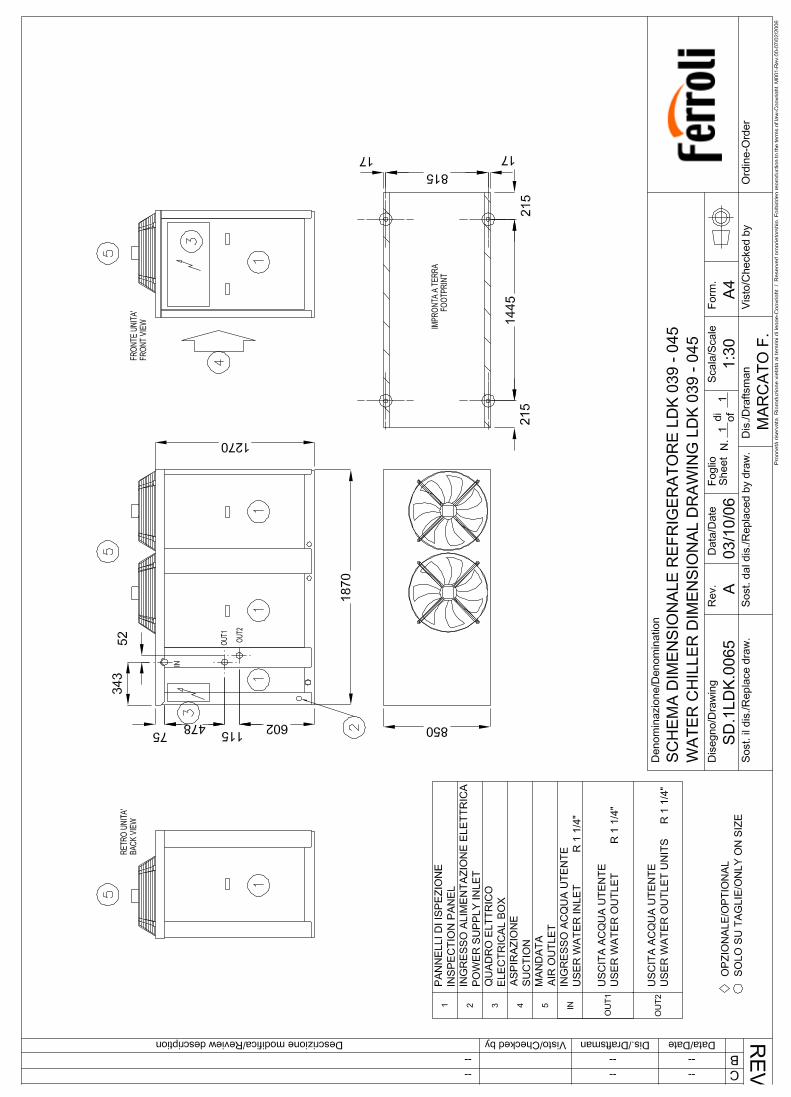
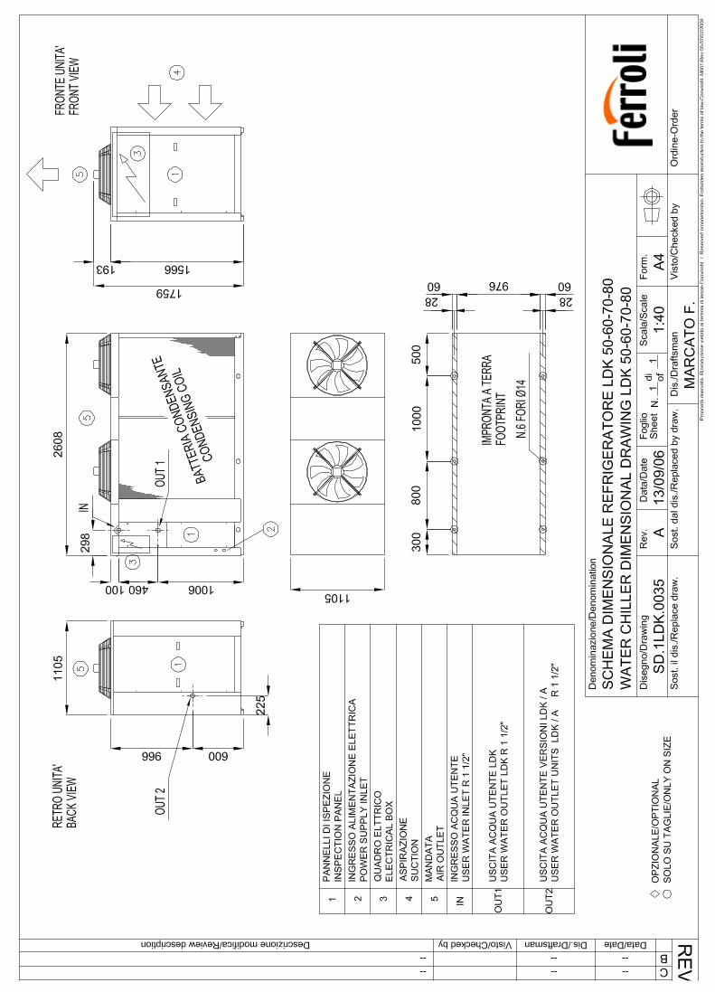
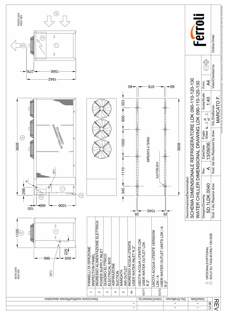
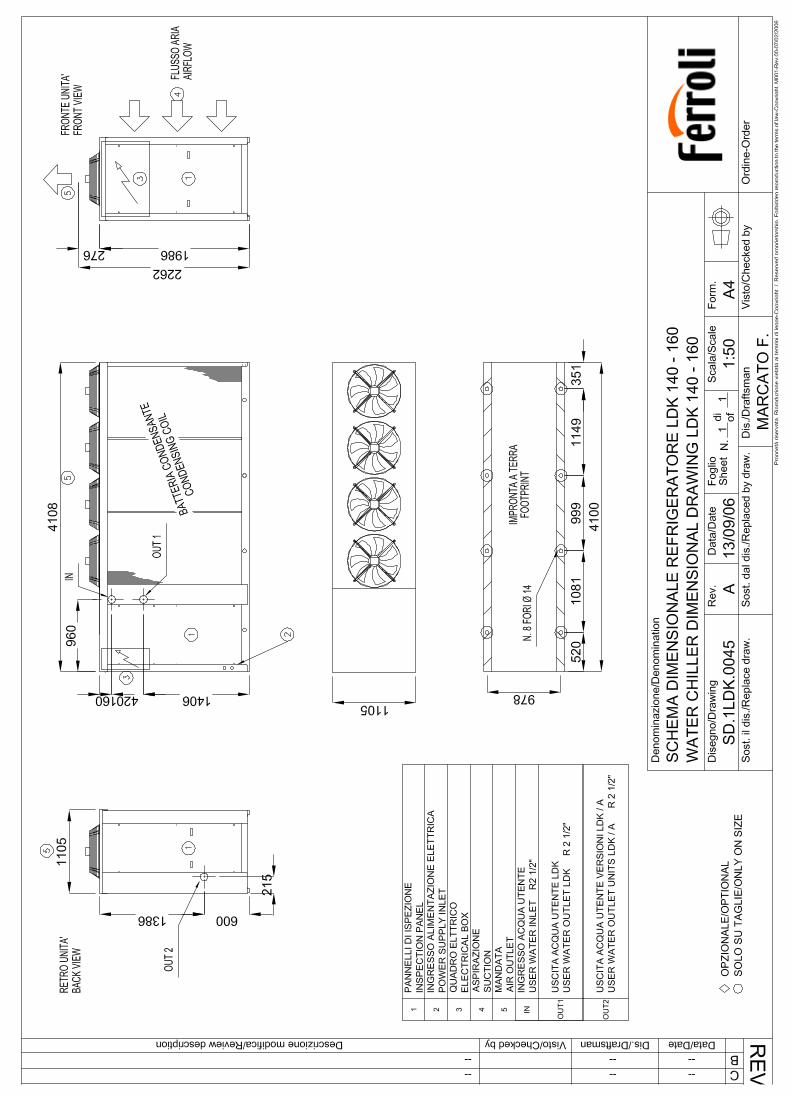
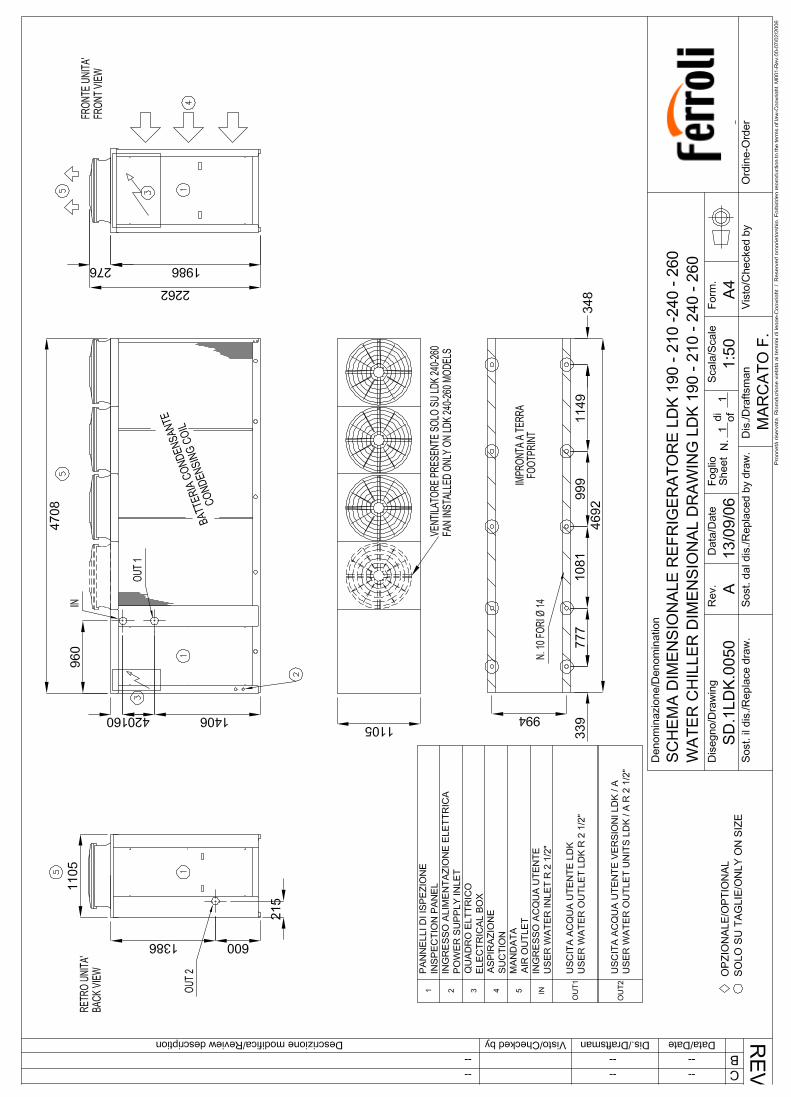
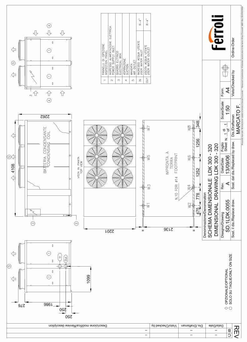
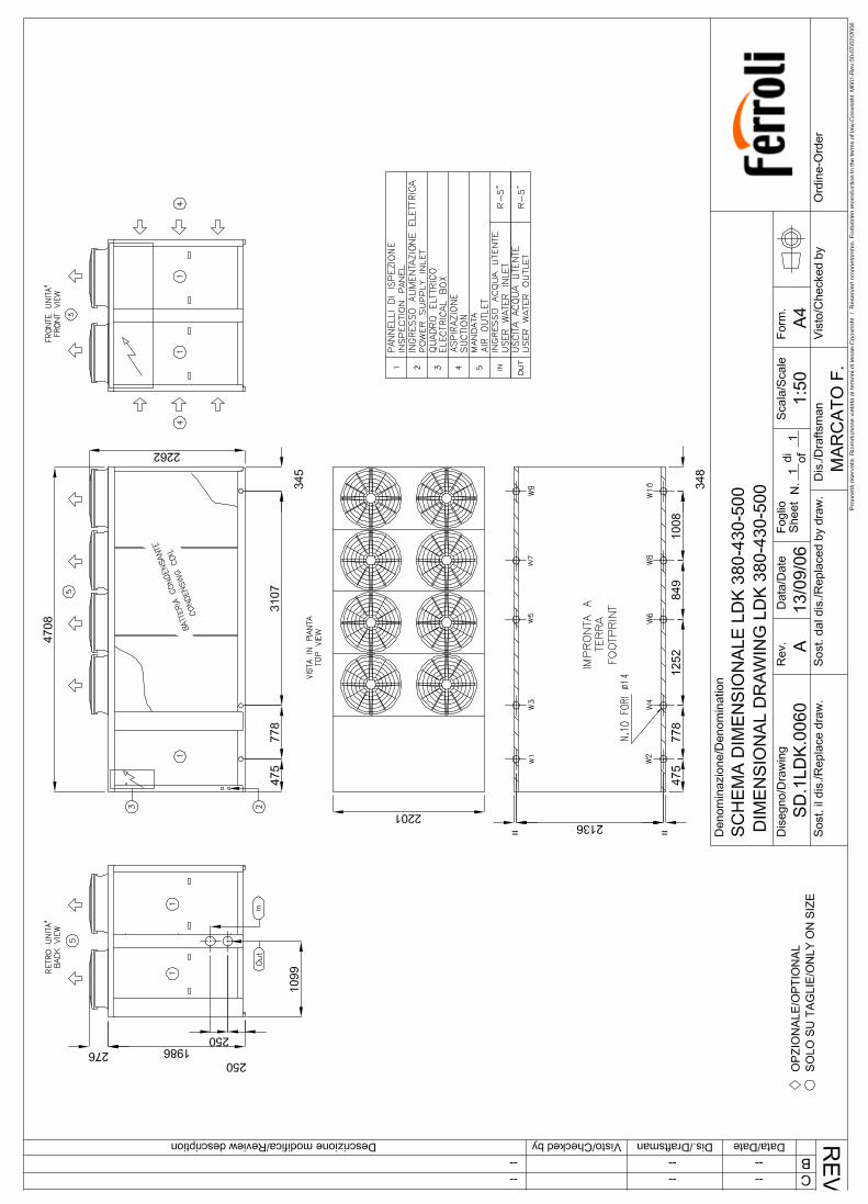
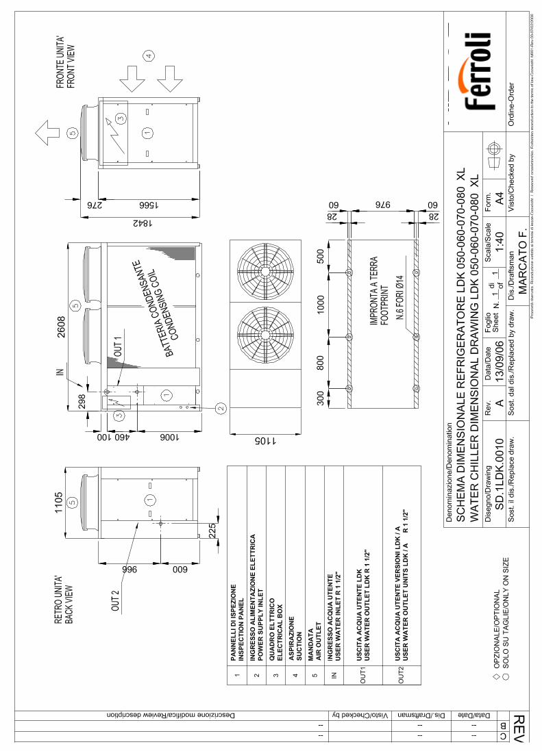
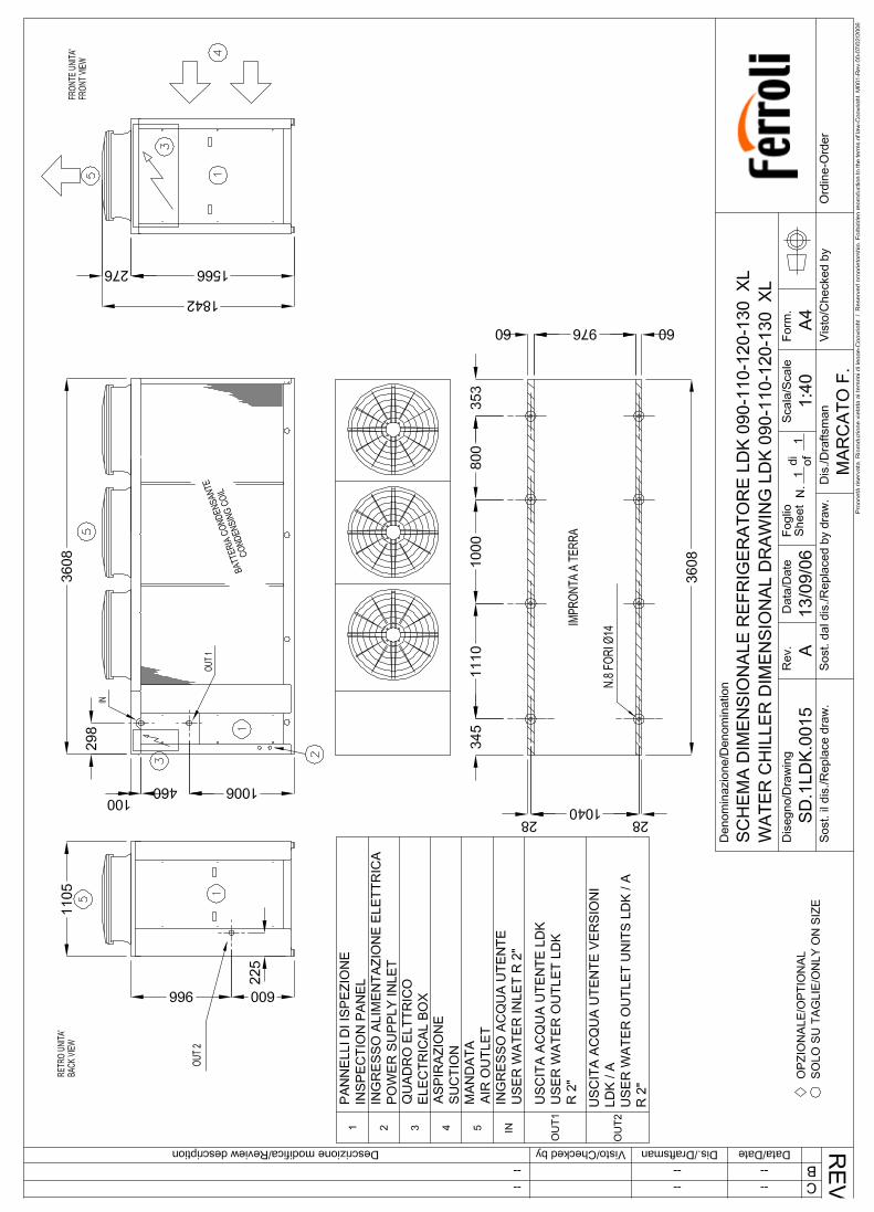
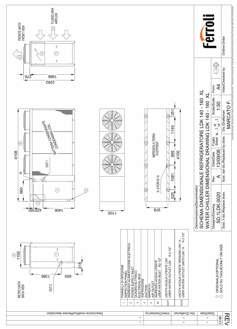
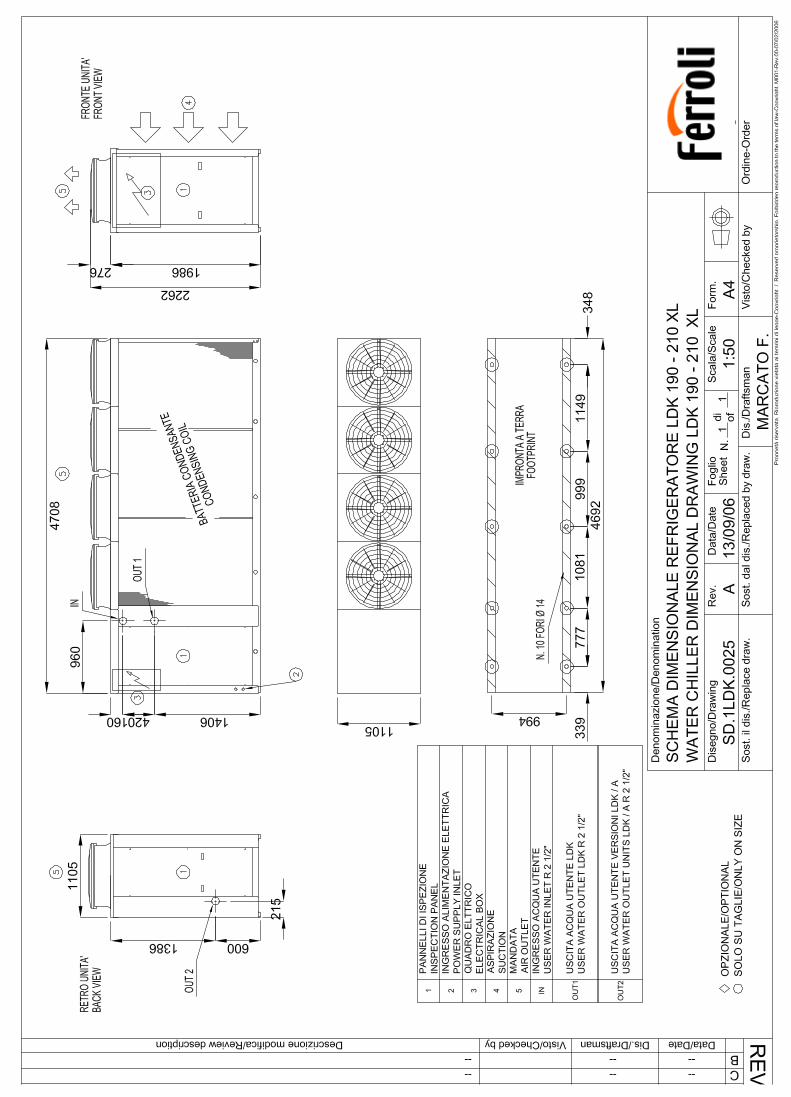

MTLDKGB REV.112006
Ferroli spa ¬37047 San Bonifacio (Verona) Italy ¬ Via Ritonda 78/Atel. +39.045.6139411 ¬ fax +39.045.6100933 ¬ www.ferroli.it