Embed Size (px)
Citation preview

air duct systems | general information and theory
Lindab 1
General information and theory 2
Safe 3
Silencers 4
Dampers and Measure units 5
Roof hoods 6
Other circular products 7
Isol 8
Transfer 9
Rectangular 10
Index 11
General information and theory

10 We reserve the right to make changes without prior notice
air duct systems | general information and theory
1
2
3
4
5
6
7
8
9
10
11
Dimensions
Designations and examplesThese designations and dimensions of ducts and fittings are adapted to CEN standards.
Lengths are given in mm.
Angles are given in degrees.
Fittings with Ød1 – Ød4 fit inside ducts and fittings with Ød.
Duct and female dimension .............................................. Ød
Connector dimension............................. Ød1, Ød2, Ød3, Ød4
Sheet metal thickness........................................................... t
Installation length ..................................................... l, l1, l2, l3
Bend radius ........................................................................ rm
Insertion length......................................................................li
Eccentricity......................................................................... cc
Component length ............................................................... L
Circumference..................................................................... O
Cross-sectional area ............................................................A
Mass.................................................................................... m
Linear mass........................................................................ ml
l 3
l
Ød 1
Ød3
Ød4
l
r m ll i
Ød1
l
ccØ
d
Ød 2
l 3
Ød3
Ød
l 3
L
Ød
Ød3
l
Ød
t

air duct systems | general information and theory
We reserve the right to make changes without prior notice 11
1
2
3
4
5
6
7
8
9
10
11
Tolerances
Bold face denotes standard dimensions.Standard face denotes intermediate dimensions.
Ducts
Length Angle
Fittings
Weight Sheet metal thickness
Ødnom
Tolerancerange
63 63,0 – 63,580 80,0 – 80,5
100 100,0 – 100,5112 112,0 – 112,5125 125,0 – 125,5140 140,0 – 140,6150 150,0 – 150,6160 160,0 – 160,6180 180,0 – 180,7200 200,0 – 200,7224 224,0 – 224,8250 250,0 – 250,8280 280,0 – 280,9300 300,0 – 300,9315 315,0 – 315,9355 355,0 – 356,0400 400,0 – 401,0450 450,0 – 451,1500 500,0 – 501,1560 560,0 – 561,2600 600,0 – 601,2630 630,0 – 631,2710 710,0 – 711,6800 800,0 – 801,6900 900,0 – 902,0
1000 1000,0 – 1002,01120 1120,0 – 1122,51250 1250,0 – 1252,51400 1400,0 – 1402,81500 1500,0 – 1502,91600 1600,0 – 1603,1
l
Ød
According to EN1506
α Tolerance
±2˚
l, l1, l3, etc Tolerance
0–15 +0-2
16–100 +0-5
101– +0-10
L ±5
Ød1, d2, d3, d4nom
Tolerancerange
linom
63 61,8 – 62,3 4080 78,8 – 79,3 40
100 98,8 – 99,3 40112 110,8 – 111,3 40125 123,8 – 124,3 40140 138,7 – 139,3 40150 148,7 – 149,3 40160 158,7 – 159,3 40180 178,6 – 179,3 40200 198,6 – 199,3 40224 222,5 – 223,3 40250 248,5 – 249,3 60280 278,4 – 279,3 60300 298,4 – 299,3 60315 313,4 – 314,3 60355 353,3 – 354,3 60400 398,3 – 399,3 80450 448,2 – 449,3 80500 498,2 – 499,3 80560 558,1 – 559,3 80600 598,1 – 599,3 80630 628,1 – 629,3 80710 708,0 – 709,3 100800 798,0 – 799,3 100900 897,9 – 899,3 100
1000 997,9 – 999,3 1201120 1117,8 – 1119,3 1201250 1247,8 – 1249,3 1201400 1397,3 – 1398,8 1501500 1496,9 – 1498,5 1501600 1596,5 – 1598,2 150
l i
Ød1According to EN1506
±10% As in sheet metal standard EN 10143:1993.

12 We reserve the right to make changes without prior notice
air duct systems | general information and theory
1
2
3
4
5
6
7
8
9
10
11
Material
Sheet metal gradeFittings and ducts in the standard Lindab range are made from hot dip galvanized steel sheet with a yield point in ten-sion of 200 N/mm2, and the zinc coating shall at least comply with Z 275.
Surface treatment of class Z 275 means 275 g zinc/m2, dou-ble sided. Z 275 thus specifies the total amount of zinc on both sides of a 1 m2 sheet. The thickness can thus be calcu-lated as follows
Zinc thickness = =
Sheet metal thicknessesOther thicknesses of sheet metal can be supplied. You will have to expect some changes to the product range, however. For example, an increase in thickness in the ducts of 0,5 mm means that the internal diameter falls by 1,0 mm, which means in turn that standard fittings do not fit, and will have to be specially made for these ducts.
Material• The following material is used in the standard range:
• Ducts and hand made fittings are made with material to EN 10142 – Fe PO2 G Z 275 MA–C.
• Pressed fittings are made with material to EN 10142 – Fe PO2 G Z 275 MA–C and EN 10142 – Fe PO6 G Z 275 MB–C
Other material can also be supplied, for example
• Stainless steel to EN 1.4436 or AISI 316 or EN 1.4301 or AISI 304. Some fittings which are normally pressed have to be hand made and swaged together.
• Aluminium to ISO/DIS 209-1. Some fittings which are normally pressed have to be hand made and swaged together.
• Plastic coated products
Ducts are made from "Plastisol” as standard, i.e. hot dip gal-vanised steel sheet Z 275, with an internal and external coating,100 µm thick, of polyvinyl chloride (PVC).
Fittings are made, as standard, from hot dip galvanised steel sheet Z 275 and then powder coated internally and externally with a mixed powder consisting of epoxy and polyester (PE) to a thickness of 80 µm.
Ducts can also be supplied with an optional coating of epoxy + PE. This can be done either both internally and externally, or only on the inside or outside. Powder-coated ducts elimi-nate the risk of differing shades in colour between ducts and fittings.
Standard colours are white NCS S0502-Y 30 gloss units ac-cording to Gardner 60° and brown NCS S7010-Y70R 45 gloss units.
NOTE! For ducts of Ø<100, the maximum length is 1,5 m for internal coating.
Fittings can optionally be coated on only the inside or out-side.
Powder coating can be optionally obtained in thicknesses of up to 200 µm.
• Aluzink with surface treatment to AZ 185 means 185 g aluzink/m2 double sided. Some fittings which are normally pressed have to be fabricated and swaged together.
zinc weightno. of sides × zinc density-----------------------------------------------------------
0 275,2 7140⋅-------------------= 10
6⋅ 19µm=

air duct systems | general information and theory
We reserve the right to make changes without prior notice 13
1
2
3
4
5
6
7
8
9
10
11
Material
Temperature limits for our materialsThe shadowed fields denote standard versions.
1 Discoloration occurs at about 200 °C in galvanized steel. This is mostly an appearance problem and does not mean impaired corrosion protection in a normal environment.
2 If the temperature rises to about 300 °C, the adhesion of the zinc is impaired, which means poorer corrosion protection.3 Aluminium sheet will soften after a couple of years at 200 °C.
Product Material/type
OperationContinual Intermittent
Temperature limitmin°C
max°C
min°C
max°C
Pressed and seam welded
Galvanized steel sheet metal 2001 2502
Aluminium sheet metal 2003 300Stainless steel sheet metal 500 700PVC coated sheet steel metal 60PE-/EP coated products 60
Swaged, spot welded and/or blind interlocked joint
Aluzink sheet metal 315Mastic -40 70
Safe gasket and damper blade seals
EPDM rubber -30 100 -50 120Silicone rubber -70 150 -90 200
Foam rubber seal EPDM rubber -30 100 -50 120Foam plastic gasket Polyester -40 70
Damper shaft bearingsPolyamide -30 150 -50 200Brass 300
to constant flow units Teflon (PTFE) 150 200
Damper actuatorElectric -30 50Pneumatic -5 60
Duct filter Polyester 120
Drain hoseEtheylene vinyl acetate and polyethylene
-45 65
InsulationGlass wool 200Rock wool 700
Silencer Polyester 130 180

air duct systems | general information and theory
14 We reserve the right to make changes without prior notice
1
2
3
4
5
6
7
8
9
10
11
The SI system
UnitsThe SI system (Système lnternational d'Unités) is used in this catalogue, in accordance with international practice. Units may be given in the “technical system” in diagrams and tables, in parallel with the SI system.
Some basic unitsFor length metre m
For mass kilogramme kg
For time second s
For electric current ampere A
For temperature kelvin K
Some derived unitsFor frequency hertz Hz 1 Hz = 1/s
For force newton N 1 N = 1 kg · m/s²
For pressure, mechanical stress pascal Pa 1 Pa = 1 N/m2
For energy, work joule J 1 J = 1 N · m
For power watt W 1 W = 1 J/s
For electric potential, electric tension volt V 1 V = 1 W/A
Some additional unitsFor time minute min 1 min = 60 s
hour h 1 h = 3 600 s = 60 min
For flat angles degree ° 1° = 1/360 of a circle
For volume litre l 1 l = 1 000 cm³ = 1 dm³
Some multiple prefixesIndex Designation Des. Example
1012 tera T 1 terajoule 1 TJ
109 giga G 1 gigawatt 1 GW
106 mega M 1 megavolt 1 MV
103 kilo k 1 kilometre 1 km
102 hecto h 1 hectogramme 1 hg
101 deca da 1 decalumen 1 dalm
10-1 deci d 1 decimetre 1 dm
10-2 centi c 1 centimetre 1 cm
10-3 milli m 1 milligramme 1 mg
10-6 micro µ 1 micrometre 1 µm
10-9 nano n 1 nanohenry 1 nH
10-12 pico p 1 picofarad 1 pF

air duct systems | general information and theory
We reserve the right to make changes without prior notice 15
1
2
3
4
5
6
7
8
9
10
11
The SI system
Conversion factorsTables for conversion to other dimensions are given for some of the units commonly used in the industry.
Pressure, p
Length, l
Area, A
Volume, V
Velocity, v
PapascalN/m2
mm wcmm Aq
mm H2Omm Hg
(at 20 °C)
in wg" wgin wc
psi(g)ibf/in2 bar
1 0,102 0,007 53 0,004 02 0,000 145 0,000 010 0
9,79 1 0,073 7 0,039 4 0,001 42 0,000 097 9
133 13,6 1 0,534 0,019 3 0,001 33
249 25,4 1,87 1 0,036 1 0,002 49
6 895 704 51,9 27,7 1 0,068 9
100 000 10 215 753 402 14,5 1
ininch
ftfoot
ydyard
mmetre mile
1 0,083 3 0,027 8 0,025 4 0,000 015 8
12,0 1 0,333 0,305 0,000 189
36,0 3,00 1 0,914 0,000 568
39,4 3,28 1,09 1 0,000 621
63 360 5 280 1 760 1 609 1
in2
sq inft2
sq ftyd2
sq ydm2
sq metre arha
hectare
1 0,006 94 0,000 772 0,000 645 0,000 006 45 0,000 000 064 5
144 1 0,111 0,092 9 0,000 929 0,000 009 29
1 296 9,00 1 0,836 0,008 36 0,000 083 6
1 550 10,8 1,20 1 0,010 0 0,000 100
155 000 1 076 120 100 1 0,010 0
15 500 031 107 639 11 960 10 000 100 1
in3
cu inl
litreUS galgallon
UK galgallon
ft3cu ft
yd3
cu ydm3
cubic metre
1 0,016 4 0,004 33 0,003 60 0,000 579 0,000 021 4 0,000 016 4
61,0 1 0,264 0,220 0,035 3 0,001 31 0,001 00
231 3,79 1 0,833 0,134 0,004 95 0,003 79
277 4,55 1,20 1 0,161 0,005 95 0,004 55
1 728 28,3 7,48 6,23 1 0,037 0 0,028 3
46 656 765 202 168 27,0 1 0,765
61 024 1 000 264 220 35,3 1,31 1
ft/minfpm
km/hBz ft/s
mile/hmph
knotkn m/s
1 0,018 3 0,016 7 0,011 4 0,009 87 0,005 08
54,7 1 0,911 0,621 0,540 0,278
60,0 1,10 1 0,682 0,592 0,305
88,0 1,61 1,47 1 0,869 0,447
101 1,85 1,69 1,15 1 0,514
197 3,60 3,28 2,24 1,94 1

air duct systems | general information and theory
16 We reserve the right to make changes without prior notice
1
2
3
4
5
6
7
8
9
10
11
The SI system
Conversion factors
Volume flow, qv
Mass, m
Mass flow, qm
Density, ρ
Force, F
Torque, M
Energy, work, E
ft3/hcfh l/min m3/h
ft3/mincfm l/s m3/s
1 0,472 0,028 3 0,016 7 0,007 87 0,000 007 87
2,12 1 0,060 0 0,035 3 0,016 7 0,000 016 7
35,3 16,7 1 0,589 0,278 0,000 278
60,0 28,3 1,70 1 0,472 0,000 472
127 60,0 3,60 2,12 1 0,001 00
127 133 60 000 3 600 2 119 1 000 1
ozounce
lbpound
kgkilogramme
1 0,062 5 0,028 3
16,0 1 0,454
35,3 2,20 1
lb/min kg/s
1 0,007 56
132 1
kg/m3 lb/ft3 g/cm3 lb/in3
1 0,062 4 0,001 00 0,000 036 1
16,0 1 0,016 0 0,000 579
1 000 62,4 1 0,036 1
27 680 1 728 27,7 1
Nnewton
lbfpound-force
kpkilopond
1 0,225 0,102
4,45 1 0,454
9,81 2,20 1
lbf · in Nm lbf · ft kpm
1 0,113 0,083 3 0,011 5
8,85 1 0,738 0,102
12,0 1,36 1 0,138
86,8 9,81 7,23 1
Jjoule
Nm, WsBtu
British thermal unitkcal
kilocalorie kWh
1 0,000 948 0,000 239 0,000 000 278
1 055 1 0,252 0,000 293
4 187 3,97 1 0,001 16
3 600 000 3 412 860 1

air duct systems | general information and theory
We reserve the right to make changes without prior notice 17
1
2
3
4
5
6
7
8
9
10
11
The SI system
Conversion factors
Power, P
Temperature difference, temperature change, ∆T for K; ∆ϑ for °C
Associated temperatures
Conversion between temperatures°C = (°F - 32) × 5/9 °C = K - 273,15
°F = °C × 9/5 + 32 K = °C + 273,15
Greek lettersGreek letters are used in technical and scientific texts to denote physical units. Minor variations in the shapes of the letters can be tolerated, on condition that this does not cause any risk of confusion.
Btu/h
Wwatt
Nm/s, J/s kcal/h
hkmetric
horsepower
hpUK, US
horsepower
1 0,293 0,252 0,000 398 0,000 393
3,41 1 0,860 0,001 36 0,001 34
3,97 1,16 1 0,001 58 0,001 56
2 510 735 632 1 0,986
2 544 746 641 1,01 1
Kkelvin
°Fdegree Fahrenheit
°Cdegree Celsius
1 1,80 1,00
0,556 1 0,556
1,00 1,80 1
K °F °C Physical state
0,00 -460 -273 Absolute zero
255 0,00 -17,8 Mixture of sal ammoniac and snow
273 32,0 0,00 Melting point of ice
293 68,0 20,0 Standard atmospheric temperature
311 100 37,8 Normal temperature of human body
373 212 100 Boiling point of water
Name Lower case Upper case
alfa α Αbeta β Βgamma γ Γdelta δ ∆epsilon ε Εzeta ζ Ζeta η Ηteta ϑ Θjota ι Ιkappa κ Κlambda λ Λmy µ Μ
Name Lower case Upper case
ny ν Νksi ξ Ξomikron ο Οpi π Πro ρ Ρsigma σ Σtau τ Τypsilon υ Υfi ϕ Φki χ Χpsi ψ Ψomega ω Ω

18 We reserve the right to make changes without prior notice
air duct systems | general information and theory
1
2
3
4
5
6
7
8
9
10
11
Pressure
Total pressure = dynamic pressure + static pressureThe static pressure in the atmosphere varies with the weather - high pressure or low pressure - and with the height above sea level. The standard pressure, atmospheric pres-sure at sea level is:
101,3 kPa = 1,013 bar = 1013 mbar(= 1 atm = 760 mm Hg)
At one particular point, such as in a ventilation duct, the stat-ic pressure comes from all sides.
In a ventilation system, the static pressure is related to the ambient atmospheric pressure outside the duct system; the static pressure can thus be positive - higher than ambient at-mospheric, or negative - lower than ambient atmospheric pressure.

air duct systems | general information and theory
We reserve the right to make changes without prior notice 19
1
2
3
4
5
6
7
8
9
10
11
Pressure
Pressure dropIf you produce a static pressure difference in an open duct system, you can get the air to flow from a point of higher pressure to a point of lower pressure - from the atmosphere via the inlet grating to the suction side of the fan, and from the supply side of the fan via the supply terminals back to the atmosphere. The pressure difference is converted into kinetic energy.
Dynamic pressure is a measure of the kinetic energy of the moving air. The connection between pressure and energy is easy to see if you use SI system unitsPa = N/m2 = Nm/m3 = J/m3 i.e. energy (in J) per unit volume (in m3) of the flowing air.
The dynamic pressure depends on
with the units
Flow in a duct system is normally not free of loss. Friction losses occur and the air is forced to change direction. It re-quires pressure (i.e. energy) to manage both dynamic and static pressure - the sum of these two is referred to as total pressure.
pt = ps + pd
Since ps will be negative in relation to atmospheric pressure (on the suction side of the fan), this means that pt will also be negative if the total of ps and pd is negative.
Pressure drop and flow losses
In a ventilation system, you want to get air moving! Clean air is to be supplied to the occupancy zone and polluted air must leave the room, process or machine. Energy is needed to move the air, which is added via the fan, which gets the air moving.
In order to flow through a duct system, air has to overcome two types of flow resistances or pressure drops:
• friction loss between the flowing air and the duct walls.
• single loss when the air changes direction or speed.
Friction loss (also known as the R value) is expressed in the
unit Pa/m
where
∆pf = friction loss per metre (Pa/m)
λ = friction factor related to duct material and surface rough-ness
dh = hydraulic diameter of the duct, the diameter of a circular duct which gives the same friction pressure drop at the same flow velocity as a rectangular duct
where a and b are duct sidesFor a circular duct, dh = d
ρ = air density (kg/m3)
v = average velocity of the air (m/s)
pd ρ v2
2-----⋅=
kg
m3------- m
s-----⎝ ⎠
⎛ ⎞ 2⋅ kg
m3------- m2
s2-------⋅ kgm
s2------------ m
m3-------⋅ N 1
m2-------⋅ N
m2------- Pa= = = = =
∆pfλdh------ ρv2
2-----⋅=
dh2 a b⋅ ⋅a b+
-------------------=

20 We reserve the right to make changes without prior notice
air duct systems | general information and theory
1
2
3
4
5
6
7
8
9
10
11
Pressure
Pressure drop calculation
Fan pressure capacity requiredLet us do a pressure drop calculation for a simple duct sys-tem!
Add up the pressure drops on the far right of the table. Then select a suitable fan which gives the required flow q = 500 l/s and a total pressure rise of pt = 125 Pa.
13
12
11
10
9
5 87643
2
1
• Number the fittings, in the direction of air flow.
• Then put the dimension and data of each component in a table as in the example.
• Read the pressure drop from the graph for each component. You can follow this example from the reduced scale graphs below.
200
100
50
10
53,3
0,2
0,5
1
15
[Pa]
100 500
100–
63
125–
80
160–
100
200–
125
250–
160
315–
200
400–
250
500–
315
630–
400
1000 5000 10000
50 100 500 1000 5000 [l/s]
[m3/h]
Flow q
Pre
ssur
e dr
op ∆
pt
RCU SR BSU 90° SLBU 100
RCFU HF
200
100
50
10
5,3
2
0,2
0,5
1
15
[Pa]
100 500
80–6
3
100–
80
125–
100
160–
125
200–
160
250–
200
315–
250
400–
315
500–
400
630–
500
1000 5000 10000
50 100 500 1000 5000 [l/s]
[m3/h]
Flow q
Pre
ssur
e dr
op ∆
pt
RCURCFU
5 10 50 100 5001000 5000 10000 50000
Flow q
0,02
0,05
0,1
0,5
11,5
4,810
50
100
200
Spe
cific
pre
ssur
e dr
op ∆
p t
2
34
5
10
15
20 Dimension ød [mm]
Hastig
het v
[m/s
]
[l/s]
[Pa/m]
6380
100
125
160
200
250
315
400
500
630
800
1000
1250
10 50 100 500 1000 5000 10000 50000 100000 [m3/h]
200
100
50
10
5
0,2
0,5
1
15
[Pa]
100 500
80–6
3
100–
80
125–
100
160–
125
200–
160
250–
200
315–
250
400–
315
500–
400
630–
500
1000 5000 10000
50 100 500 1000 5000 [l/s]
[m3/h]
Flow q
Pre
ssur
e dr
op∆
p t
100
50
1014
5,5
110
50 100 500
80 100 125 160 200 250 315Dimension Ød1 [mm]
1000 5000 10000
50 100 500 1000 3000 [l/s]
[m3/h]Flow q
Pre
ssur
e dr
op ∆
pt [
Pa]
500
1000
30
500 1000 5000 10000
50 100 500
1250
1000
800
630
500400
40
50
60
70
80
90
1000 5000 10000
100
50
22
10
Dimension Ød [mm]
[l/s]
[m3/h]
Flow q
Pre
ssur
e dr
op ∆
pt [
Pa]
Sound power level LWA [dB]
315 1
200
90060
0
400 1
200
90060
0
500
1200
900
630
1500
1200
900
800 1
500
1200
0,5
1
10
5
42
100
500
500 1000 5000 10000 30000
100 500 1000 5000 10000 [l/s]
[m3/h]
Flow q
[Pa] Dimension Ød1 [mm]
Pre
ssur
e dr
op ∆
pt
1 2 4 7 9 11 3
6 10 12 13
8 5
No Flowl/s
ComponentDenom.
DimensionØ mm
Lengthm
PressuredropPa/m
PressuredropPa
2
3
4
5
6
7
8
9
10
11
12
13
1 500
"
"
"
"
"
"
"
"
"
"
"
"
RCU
SR
BSU 90°
SR
SLBU 100
RCFU
SR
BSU
SR
RCU
SR
RCFU
HF
500-315
315
315
315
315/1200
315-250
250
250
250
315-250
315
400-315
400
-
2
-
1,6
1,2
-
1,5
-
1,2
-
3,5
-
-
-
1,5
-
1,5
-
-
4,8
-
4,8
-
1,5
-
-
3,3
3,0
5,5
2,4
42,0
5,0
7,2
14,0
5,8
6,0
5,3
2,0
22,0
Total pressure drop (sum of rows 1 – 13) = 123,4

air duct systems | general information and theory
We reserve the right to make changes without prior notice 21
1
2
3
4
5
6
7
8
9
10
11
Pressure
PrerequisitesIn order to correctly dimension a duct system you need infor-mation about the total pressure drops of the fittings.
The total pressure drop ∆ pt (Pa) between two sections, 1 and 2, in a duct system is defined by
pt = pt1 - pt2 = (ps1+pd1) - (ps2+pd2)
where and
It is assumed in pressure drop calculation of ventilation ducts that:
• incompressible flow, i.e. air density does not change
• isothermal relationship, i.e. no exchange of heat between the duct and its surroundings occurs
• no changes in potential energy, i.e. height differences between the various sections of the duct system are neglected
Designations usedl = length m (mm)
a = long side m (mm)
b = short side m (mm)
r = radius m (mm)
d = diameter m (mm)
dh = hydraulic diameter m (mm)
Ac = cross sectional area m2
pA = atmospheric pressure mbar
ps = static pressure Pa
pd = dynamic pressure Pa
pt = total pressure Pa
∆p = pressure drop Pa
∆pt = total pressure drop Pa
ϑ = temperature °C
v = air velocity (average) m/s
q = air flow m3/s
ρ = density kg/m3
α = angle °
ϕ = relative humidity %
λ = friction number
R = coefficient of friction Pa/m
ζ = resistance number
ν = kinematic viscosity m2/s
The total pressure drops for the most common fittings are shown in graphs, as a function of air flow (or velocity in some cases).
The basic data for the graphs comes from measurements and calculations done at our laboratories. Some graphs are taken from litterature.
The graphs apply to air under standard conditions.
ν = 15,1 · 10-6 m2/s
ϑ = 20 °C
ρ = 1,2 kg/m3
ϕ = 65 %
pA = 1013,2 mbar
For air of other density (ρother) the flow (qother_density) is obtained from the formula
qother_density =
Ac1
ps1
v1
Ac2
ps2
v2
Section 1 Section 2
pdρ v2⋅
2-------------= v q
Ac------=
qgraph1,2
ρother---------------⋅

22 We reserve the right to make changes without prior notice
air duct systems | general information and theory
1
2
3
4
5
6
7
8
9
10
11
Sound
Ventilation does not have to be noisy!
SourceWaves on water
We throw a stone onto completely calm water.
Waves in air
We fire a starter´s gun.
DistributionWaves on water
Waves on water spread out in increasing concentric circles from the centre, where the stone hit the water.
Waves in air
Sound waves spread out in the air, in all directions, in an in-creasing ball from the centre, i.e. the gun.
If you use your common sense, and construct your air treat-ment system with consideration and good components, you can often avoid problems and complaints.
Fans make noise, this is something you can not do a lot about. But you can prevent the noise from getting into the ar-eas connected to the fan system - you can absorb and damp the noise on the way.
This description does not claim to teach you how to calculate and attenuate noise in a ventilation system - there are books available on this.
This description only aims at providing information about a few simple rules and hints, which together with common sence can be enough for simple installations.
You must have some basic knowledge about how and where noise is generated, transmitted and attenuated in the system, to be table to choose the correct principle and correct com-ponents. To take a simple analogy: noise transmission con-sists of waves in a medium, i.e. air, which we can not see. This is very similar to the way waves spread on water.
Let us examine the analogy, to make the comparison clearer:

air duct systems | general information and theory
We reserve the right to make changes without prior notice 23
1
2
3
4
5
6
7
8
9
10
11
Sound
Energy transportWaves on water
Kinetic energy is transmitted from molecule to molecule in the water. They bounce against each other. Molecules move back and forwards. Energy spreads from the source.
Waves in air
Kinetic energy is transmitted from molecule to molecule in the air. They bounce against each other, and move back and forwards. Energy spreads from the source.
DistanceWaves on water
When waves depart from the centre, where the stone hit, the wave height becomes lower and lower, until they are invisi-ble. The water is calm again.
Waves in air
When sound waves depart from the source, the starter´s gun, wave movement drops off and the sound becomes weaker and weaker until it can no longer be heard.
IntensityWaves on water
The energy which started the wave propagation, or the pow-er needed to keep it going, is distributed across an increas-ing area as the distance, the radius, increases.
Waves in air
The energy which started the wave propagation, or the power needed to keep it going, is distributed across an increasing volume as the distance, the radius, increases.
Obstruction in the wayWaves on water
If waves in water encounter the side of a boat or jetty, they will be reflected at the same angle as they met the obstruc-tion.
Waves in air
If waves in air encounter a wall, they will be reflected at the same angle as they met the obstruction.
Energy lossWaves on water
The reflected wave height is lower than the incident wave. Some of the kinetic energy is absorbed in the collision with the jetty side (and is converted into heat).
Waves in air
The reflected wave movement is lower than the incident wave. Some of the kinetic energy is absorbed in the collision with the wall (and is converted into heat)
The ball moves more slowly when it bounces back than when it hits the wall.
In the same way as when you bounce a ball on the wall.

24 We reserve the right to make changes without prior notice
air duct systems | general information and theory
1
2
3
4
5
6
7
8
9
10
11
Sound
Sound can be absorbedWhen sound waves meet a soft, porous wall (mineral wool etc.), the vibrating molecules penetrate the surface layer, and are then braked by friction against the material fibres.
The part of the energy which is thus absorbed is converted to heat in the material, and the rest is reflected back into the room. This type of damping, where the sound is braked by the soft surface layer, is referred to as porous absorption.
The sound absorption ability of different materials varies. This property is expressed as the sound absorption factor α of the material.
If nothing is absorbed, everything is reflected, then a = 0 which makes α = 0:
i = 0 + r
If nothing is reflected, everything is absorbed, then r = 0 which makes α = 1:
i = a + 0
An open window can be said to have α = 1, all sound from the room which arrives at the window disappears out!
In hard materials, such as concrete or marble surfaces, virtu-ally no sound energy is absorbed, everything is reflected and the α value is near to zero. In rooms with hard surfaces, the sound bounces for a long time before it dies out. The room has a long reverberation time and we get a strong, unpleas-ant echo. The sound level caused by normal sound sources becomes high.
In soft materials, such as thick mineral wool boards, the op-posite happens. The α value is close to 1. Sometimes, exces-sively damped, soft rooms are unsuitable “You can’t hear what you say”. Avoid extremes - the reverberation time in a room should be chosen to suit the activities there.
Sound, in a ventilation system, moves just as easily with or against the direction of flow.
Sound which moves through a duct system will be damped in several ways. Let us start off with bare metal duct walls.
Metal walls also absorb - but not muchWhen the metal duct walls are hit by the sound wave, they will start to vibrate at the same frequency as the sound.
The movements are normally very small, and hardly visible to the naked eye (it is often easier to feel the vibration, with your fingertips on the sheet metal).
What happens is the same as when a window vibrates when a heavy truck passes by on the street.
The duct panels and the window will then function as membrane dampers - boards which are made to vibrate by the incident sound energy. But this movement is not without friction, since it is braked by both the bending strength of the sheet, and (mostly) by the connection around the edges of the sheet. As previously, with the porous damper, some of the energy is converted into heat - the sound which remains has become weaker and has been damped.
Given the same free duct area, a circular, spiral seamed duct is stiffer than a rectangular one and will thus provide less damping.
As shown in the illustration on the next page, damping in un-lined ducts is relatively modest. For this reason, it is normally ignored when the noise in the installation is calculated, it is instead used as the margin of safety.
Attenuation in straight sheet metal ducts(1 mm sheet metal thickness)
ai = a + r α = —a
i
r
i
α 0i--- 0= =
α aa--- 1= =
125 250 500 1000 2000 4000 Hz
1,0
α-value
Mineral wool 100 mm
0,5
0
Mine
ral w
ool 5
0 m
m
Mineral wool 25 mm
Concrete
Window glass
Soft carpet on concrete floor

air duct systems | general information and theory
We reserve the right to make changes without prior notice 25
1
2
3
4
5
6
7
8
9
10
11
Sound
Attenuation in straight sheet etal ducts(1 mm sheet metal thickness)
Absorption is more effectiveThe damping becomes more effective if we put absorbent material into the duct system. The way that sound is damped was described above, part of the sound energy is absorbed by the absorption material which is hit by the sound.
If the sound waves bounce enough times against porous sur-faces, the remaining sound energy, the kinetic energy which makes your eardrums vibrate, will be so low that it does not cause annoyance!
Where should you put the absorption material in the ducts?The answer is obvious - where the material comes into con-tact with the greatest number of sound waves. Noise which travels along a long, unlined, straight duct will be directed by reflection against the duct walls. Absorption material here is of less use than if it is put in a bend, a suction or pressure ple-num chamber or in a straight duct just after a fan, or any-where where we have “turbulent sound flow”. The more times sound bounces against the soft sides, the more useful the material becomes.
Why the curved silencer BSLU is so effective!
Straight silencers concentrate the absorption materialThere is a complement to the description of sound waves above. When the sound waves travel along a porous surface, they will be deflected towards the duct walls. This deflection is called, “diffraction”.
This, and the way that sound propagation is disturbed by tur-bulence, gives that straight silencers can have high attenua-tion.
AttenuationdB per m
0,6
0,5
0,4
0,3
0,2
0,1
0
CB
A
De
fg
h
63 125 250 500 > 1k
Middle frequency octave band Hz
Duct dimensions
Rectangular sheet metal ducts 75–200A
Circular sheet metal ducts
800–1000D
400–800C
200–400B
Ø75–200e
800–1600h
400–800g
200–400f

air duct systems | general information and theory
26 We reserve the right to make changes without prior notice
1
2
3
4
5
6
7
8
9
10
11
Sound
As we can see from the values for SLU 50 and SLU 100, damping varies with a few simple rules:
To attenuate low frequencies (< 500 Hz) thicker absorption material is needed. –SLU 100 is more efficient than SLU 50.
To attenuate high frequencies (> 500 Hz), thinner absorption material is suffi-cient. – SLU 50 is just as effective as SLU 100.
The longer way the sound has to pass over the absorption surface the higher the attenuation. Long silencers have higher attenuation than short ones. –SLU with l = 600 attenuates more than SLU with l = 300.
The shorter distance between the ab-sorbing surfaces the higher the attenua-tion. Silencers with small diameter attenuates more than big ones. – SLU Ø 80 attenuates more than SLU Ø 250.
For the same reason, an extra baffle gives higher attenuation than a silencer of the same diameter, but without a baf-fle. – SLBU 100 attenuates more than SLU 100.
SLU 50 SLU 100Ød1nom
lmm
Attenuation in dB for centre frequency Hz63 125 250 500 1k 2k 4k 8k
80 300 1 5 6 13 21 28 28 1780 600 1 7 11 23 35 50 50 2580 900 2 9 16 33 49 50 50 3380 1200 3 11 21 42 50 50 50 41
100 300 1 5 6 14 20 24 22 12
Ød1nom
lmm
Attenuation in dB for centre frequency Hz63 125 250 500 1k 2k 4k 8k
80 300 3 7 9 16 20 28 28 1380 600 5 11 16 26 35 50 50 2580 900 7 16 24 37 50 50 50 3880 1200 9 20 31 47 50 50 50 50
100 300 2 7 10 13 18 23 22 13
SLU 50 NOTE!The attenuation is not directly propor-tional to the length. The reason for this is that you get an extra attenuation at the silencers openings, and all silenc-ers have two openings irrespective of their length.
Ød1nom
lmm
Attenuation in dB for centre frequency Hz63 125 250 500 1k 2k 4k 8k
80 300 1 5 6 13 21 28 28 1780 600 1 7 11 23 35 50 50 2580 900 2 9 16 33 49 50 50 3380 1200 3 11 21 42 50 50 50 41
100 300 1 5 6 14 20 24 22 12
SLU 50Ød1nom
lmm
Attenuation in dB for centre frequency Hz63 125 250 500 1k 2k 4k 8k
80 300 1 5 6 13 21 28 28 1780 600 1 7 11 23 35 50 50 2580 900 2 9 16 33 49 50 50 3380 1200 3 11 21 42 50 50 50 41
100 300 1 5 6 14 20 24 22 12
250 600 1 2 6 13 18 17 8 7250 900 1 3 7 18 24 24 11 9250 1200 2 3 9 23 29 32 13 10315 600 1 3 5 10 15 10 5 6
SLU 100 SLBU 100Ød1nom
lmm
Attenuation in dB for centre frequency Hz63 125 250 500 1k 2k 4k 8k
80 300 3 7 9 16 20 28 28 1380 600 5 11 16 26 35 50 50 2580 900 7 16 24 37 50 50 50 3880 1200 9 20 31 47 50 50 50 50
100 300 2 7 10 13 18 23 22 13
250 900 3 6 13 15 23 25 11 9250 1200 4 8 17 20 30 34 14 10315 600 2 3 6 7 12 11 6 6315 900 3 5 11 12 19 16 8 8315 1200 5 7 15 17 25 22 10 10400 600 3 4 5 5 8 5 5 6
Ød1nom
lmm
Attenuation in dB for centre frequency Hz63 125 250 500 1k 2k 4k 8k
315 600 3 6 13 15 23 25 11 18315 900 4 8 17 20 30 34 14 22315 1200 2 3 6 7 12 11 6 25400 600 3 5 11 12 19 16 8 13

air duct systems | general information and theory
We reserve the right to make changes without prior notice 27
1
2
3
4
5
6
7
8
9
10
11
Sound
Noise frequency influences the choice of silencerAs we see in the tables above, the damping ability varies with the frequency of sound. Before we look at the choice of si-lencers, it could be a good idea to describe the concept of frequency in greater detail.
A sound source influences the surrounding air, and makes it vibrate. The character of the sound depends on the varia-tions in pressure which occur in the air.
Let us assume that the sound source is a vibrating plate - the changes in pressure, or the sound will then have the same frequency as the vibrations in the plate. The strength of the sound will depend on the amount that the plate vibrates, i.e. the amplitude of the movement. Let us start off with that:
If there is only one note, of a single frequency, the pressure will vary sinusoidally, so a pure note is referred to as a sine wave.
The characteristics of sound propagation are:
• frequency (f),which is measured in hertz, Hz, (s-1), (and specifies the number of times a second that a new sound wave arrives).
• wave length (λ, “lambda”),which is measured in metres, m, (and specifies the distance between two similar points on the curve).
and
• speed of sound (c)which is measured in m/s, (and specifies the speed of movement of the sound wave).
These three variables have the following relationship:
c = f · λ
The speed of sound in air is also a function of pressure and temperature.
At normal air pressure and + 20 °C is c ≈ 340 m/s.
A young person with normal hearing can hear sounds at fre-quencies from 20-20 000 Hz, i.e. (in air) at wavelengths rang-ing from 17 m (at 20 Hz) to app. 17 mm (at 20 kHz).
We perceive changes in sound frequency on a logarithmic scale, i.e. it is the relative frequency and not the difference in Hz which determines how a change in note is perceived. A doubling of frequency is perceived as being the same, irre-spective of whether it is a change from 100 to 200 Hz, 1000 to 2000 Hz or 10 to 20 kHz.
The logarithmic scale is usually sub-divided into octaves. i.e. in scales where the top note is twice the frequency of the bot-tom note. This has been customary in music for a long time.
Infrasound
Audible sound
Ultrasound
20 Hz 20 000 Hz
Infrasound
Audible sound
Logarithmic scale
Ultrasound
20 50 100 200 500 1000 2000 5000 10000 20000 Hz
Infrasound
Audible sound
Logarithmic scale
Ultrasound
20 50 100 200 500 1000 2000 5000 10000 20000 Hz
28 We reserve the right to make changes without prior notice
air duct systems | general information and theory
1
2
3
4
5
6
7
8
9
10
11
Sound
And in engineering.
The concept of decibelThe stronger the sound is, the harder the particles of air will bump into each other.
Sound pressure changes in the audible area can vary within very wide limits. Some sounds are so weak that we can not hear them. The so-called audible limit varies with frequency and is 20 µPa at about 1000 Hz .
Other sounds are so loud that we risk hearing damage. The pain limit, the sound pressure which causes pain in your ears also varies with frequency, but is about 20 Pa at 1000 Hz. This means that it is a million times louder than the weakest sound we can perceive.
We also perceive changes in sound pressure on a logarithmic scale. A sound level concept using the decibel (dB) as the unit, has been created to express comparable values.
The dB unit, which is used in many different applications, is generally defined as: 10 · log (X/X0), where X is the unit meas-ured, i.e. the sound pressure, and X0 is a reference level ex-pressed in the same units. The relationship of X/X0 is thus dimensionless. The reference level from which the dB unit is
specified, is given instead. This means that you generally ex-press the level in dB (above X0).
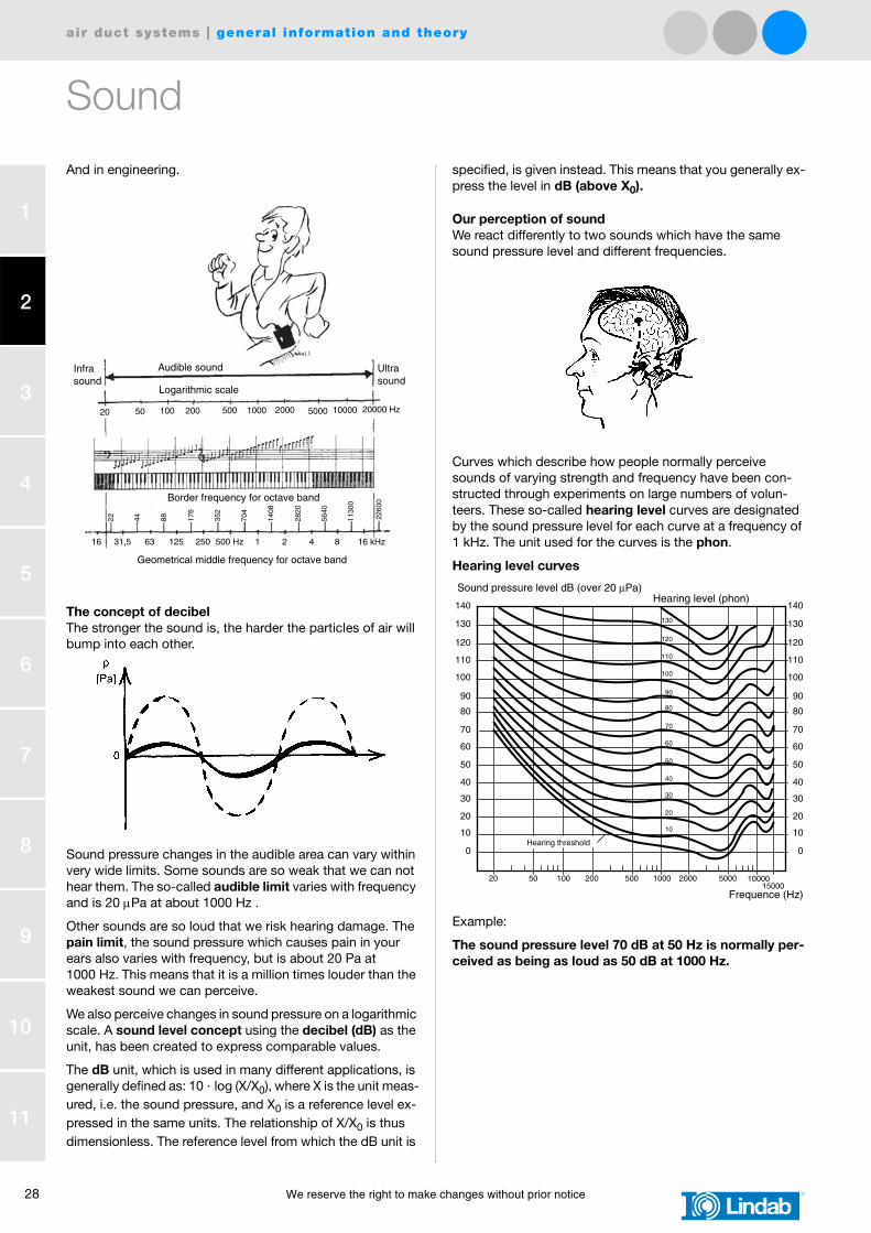
Our perception of soundWe react differently to two sounds which have the same sound pressure level and different frequencies.
Curves which describe how people normally perceive sounds of varying strength and frequency have been con-structed through experiments on large numbers of volun-teers. These so-called hearing level curves are designated by the sound pressure level for each curve at a frequency of 1 kHz. The unit used for the curves is the phon.
Hearing level curves
Example:
The sound pressure level 70 dB at 50 Hz is normally per-ceived as being as loud as 50 dB at 1000 Hz.
Infrasound
Audible sound
Logarithmic scale
Ultrasound
20 50 100 200 500 1000 2000 5000 10000 20000 Hz
Border frequency for octave band
Geometrical middle frequency for octave band
16 31,5 63 125 250 500 Hz 1 2 4 8 16 kHz
22 44 88 176
352
704
1408
2820
5640
1130
0
2260
0
140
130
120
110
100
90
80
70
60
50
40
30
20
10
0
10020 50 1000200 500 2000 500015000
Frequence (Hz)
140
130
120
110
100
90
80
70
60
50
40
30
20
10
0
Hearing level (phon)
130
120
110
100
90
80
70
60
50
40
30
20
10
10000
Sound pressure level dB (over 20 µPa)
Hearing threshold

air duct systems | general information and theory
We reserve the right to make changes without prior notice 29
1
2
3
4
5
6
7
8
9
10
11
Sound
Sound levels
Several methods are used to compare the disturbance caused by two different sounds, and where the perception of the ear to noise has been modelled.
The simplest way is to compare their “weighted” sound lev-els. The incoming sound is filtered in an electronic filter to re-duce the components, mostly the low-frequency components, where the ear is not so sensitive, and amplify the components between 1 and 4 kHz, where we are most sensitive.
Sound meters usually have three electronic filters, A-, B- and C-filter. The A-filter is mostly used these days, where the re-sult, the “weighted” sound level, is expressed in dB (A).
Choosing silencers
The fan is the primary sound source in a ventilation system, but intrusive noise can also be caused by an unsuitable choice of duct components and terminal units:
Lw = 40 + 10 · log q + 20 · log pt dB (above 1 pW)
q = air flow (in m3/s) through the fan
pt = total pressure rise (in Pa) in the fan
40 = “specific noise power level” which considers the effi-ciency of the fan at its point of operation, and the SI units for q and pt
The noise generated in the fan must be attenuated in the duct system, at some point before the room terminal unit. Some of the attenuation is “natural”, examples are given above. This attenuation is often not enough, and additional silencers can be put in the duct system - in the main channel near the fan to damp the fan noise to all the duct branches or in the branch ducts only to damp particularly sensitive rooms.
Low air speeds should be selected in the ducts, to avoid dis-turbing noise in the rooms.
• At a given air speed, a doubling of that speed corresponds to a 12 dB increase in noise levels.
Low air speeds also cut operating costs.
• At a given air speed, the fan power required increases as the square of the air speed.
In this example, calculation has shows that the existing at-tenuation in the duct system is not enough. The table shows that more attenuation is needed. What to choose?
Example
Lindab has a large range of silencers with varying character-istics and dimensions. Let us see what might fit!
31 63 125 250 500 1 2 4 8 16 kHz
2-60
-50
-40
-30
-20
-10
0
Attenuation dB (above 20 µPa)
2 5 102 2 5 103 2 5 104 Hz
C
B
A
AC
B
63 125 250 500 1k 2k 4k 8k
Before X X X X X X X X dB
After X X X X X X X X dB
Difference 2 4 9 13 20 16 8 8 dB
Duct Ø315

30 We reserve the right to make changes without prior notice
air duct systems | general information and theory
1
2
3
4
5
6
7
8
9
10
11
Sound
This is the narrowest silencer, so the longest one, 1200 mm, should be selected to meet the requirements. The deviation in the 125 Hz band, 1 dB, is small and will not be noticeable. This is one of the possible alternatives!
This silencer has a thicker layer of absorbing material (100 mm instead of 50 mm) and thus has better low frequen-cy damping, but also has a larger external diameter than SLU 50. To meet the requirements, you should choose the longer one, 900 mm. The deviations in the 500 and 1k Hz bands, 1 dB, are small and will not be noticeable. This is an other of the possible alternatives.
This silencer has the same thickness of absorbing material as SLU 100 (100 mm) but also has a 100 mm thick baffle which increases damping (but also the pressure drop across the si-lencer). You only have to choose the shortest one, 600 mm, to meet the requirements by a wide margin. The silencer manages all the octave bands by a wide margin. This is still another possible alternative.
The final choice of alternatives is determined by other con-siderations:
• SLU 50 1200if there is space lengthways, (but perhaps tight at the sides).
• SLU 100 900shorter, but needs more room at the sides.
• SLBU 100 600If the lengthways space is limited and if the slight increase in total pressure drop is not important - e.g. in a branch duct where part of the available pressure has to be restricted anyway when the air flows are adjusted.
Decide how safe the values in the sound calculation are, and choose a silencer with the corresponding margin of safety. It is always more expensive and more difficult to add damping afterwards, if it was not installed from the beginning. If the users ever become dissatisfied with the noise, it is difficult to get them to change their views!
You can find the products under Silencers at page XX.
SLU 50 63 125 250 500 1k 2k 4k 8k
600 1 3 5 10 15 10 5 6
900 2 3 7 15 21 13 7 8
1200 2 3 9 19 28 16 9 9 ←
SLU 100 63 125 250 500 1k 2k 4k 8k
600 2 3 6 7 12 11 6 6
900 3 5 11 12 19 16 8 8 ←
1200 5 7 15 17 25 22 10 10
SLBU 100 63 125 250 500 1k 2k 4k 8k
600 4 6 10 16 22 28 27 18 ←
900 5 7 16 23 30 38 32 22
1200 7 9 23 30 38 47 37 25