Embed Size (px)
Citation preview

Operation Manual
AIR FLOW TRANSDUCER MODEL 6332/6332D
Please read this manual carefully and understand the warnings described in this manual before operating the product.
Keep this manual handy for ready reference
KANOMAX JAPAN, INC.
02001 0809

Thank you for purchasing a product of Kanomax, Inc. Please read this operation manual carefully and operate the instrument appropriately by following the instructions given in this manual.
Component List
■ Standard
Item Model Remarks Airflow Transducer
Main Unit (Without Display) 6332 -
Airflow Transducer Main Unit (With Display) 6332D -
■ Probe & Cable (Sold Separately)
Item Model Remarks 0962-00 0963-00
Uni-directional
0964-01 0964-02
Omni-directional (Needle)
0965-00 0965-01
Omni-directional (Spherical)
0965-03
0965-04
Mini-temperature-compensation-sensor integrated type Omni-directional (Spherical)
0965-07
Air Velocity Probe
0965-08
Mini-temperature-compensation-sensor independent type Omni-directional (Spherical)
1504-04 Length: 10m 1504-05 Length: 20m Probe Cable 1504-06 Length: 30m
■ Optional Accessory
Item Model Remarks Display Unit 6332-01 - AC Adapter 6332-02 -
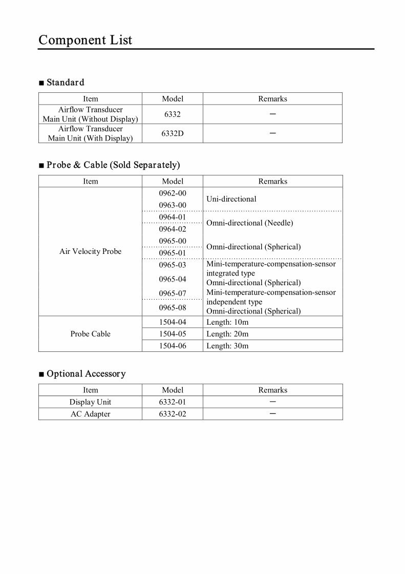
Impor tant Safety Information In this operation manual, warning types and classifications are defined as follows.
[Classifications]
Danger : To Prevent Ser ious Injury or Death Warnings in this classification indicate danger that may result in serious injury or death if not observed.
Caution: To Prevent Damage to the Product
Warnings in this classification indicate risks of damage to the product that may void the product warranty if not observed.
[Descr iption of Symbols]
This symbol indicates a condition (including danger) that requires caution. The subject of each caution is illustrated inside the triangle (e.g., high temperature caution symbol shown on the left). This symbol indicates prohibition. Do not take a prohibited action shown inside or near this symbol (e.g., disassembly prohibition symbol shown on the left). This symbol indicates a mandatory action. A specific action is given near the symbol.
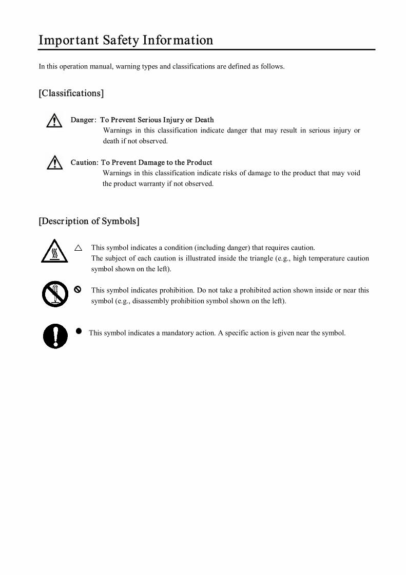
○ Never br ing the probe close to a flammable gas
atmosphere. --- The heated sensor may cause fire or explosion.
○ Never disassemble, modify or repair the instrument. --- Failure to observe the above may cause short circuit and
malfunction.
○ Use the specified voltage for power supply. --- Unspecified voltage may cause electrical shock and fire.
○ Remove dust and any impur ities from the terminal block. --- The dust/impurities may cause fire.
○ Do not use the instrument in a water vapor atmosphere.
--- Failure to observe the above may cause electrical shock,
fire, or damage to the sensor.
○ Never touch the sensor . --- The sensor is heated during operation. Touching the heated sensor
may cause burns, and also may damage the sensor itself. Particular attention must be paid to spherical type sensors (Model: 0965-00/ 0965-01/ 0965-03/ 0965-04/ 0965-07/ 0965-08) as they are very sensitive. Please Handle with care.
Water drops
Warning: High Temperature /
Injury
Do not use unspecified voltage
Danger
Do not use near flammable gas
Do not modify / disassemble
Prohibition
Handle Properly
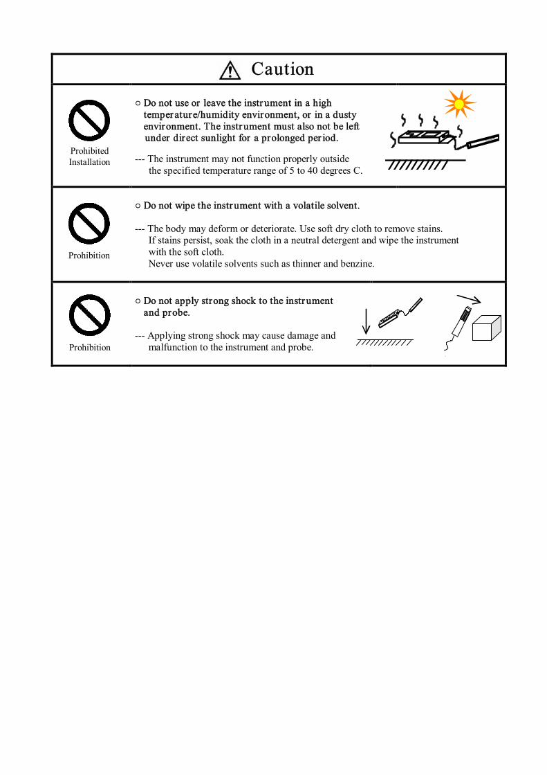
○ Do not use or leave the instrument in a high
temperature/humidity environment, or in a dusty environment. The instrument must also not be left
under direct sunlight for a prolonged per iod. --- The instrument may not function properly outside
the specified temperature range of 5 to 40 degrees C.
○ Do not wipe the instrument with a volatile solvent. --- The body may deform or deteriorate. Use soft dry cloth to remove stains.
If stains persist, soak the cloth in a neutral detergent and wipe the instrument with the soft cloth. Never use volatile solvents such as thinner and benzine.
○ Do not apply strong shock to the instrument
and probe. --- Applying strong shock may cause damage and
malfunction to the instrument and probe.
Caution
Prohibited Installation
Prohibition
Prohibition
Table of Contents
Names and Dimensions of Components...................................................... 1
System Configuration Example.................................................................... 5
Connecting the Probe Cable to the Main Unit ............................................. 6
Connecting the Probe Cable to the Probe..................................................... 6
Installing the Data ROM............................................................................... 7
Switching Output (Setting Current/Voltage and Output Range)................. 8
Connecting Output and Power Supply....................................................... 10
Measurement Method ................................................................................. 11
Optional Accessory ..................................................................................... 12
Display Unit ....................................................................................................................12 AC Adapter ....................................................................................................................13
Cleaning the Probe ...................................................................................... 14
Specification of Main Unit.......................................................................... 15
Specification of Probes (Sold Separately) .................................................. 16
Troubleshooting........................................................................................... 18
Product Warranty and After Service........................................................... 19
Contact Information .................................................................................... 20
1
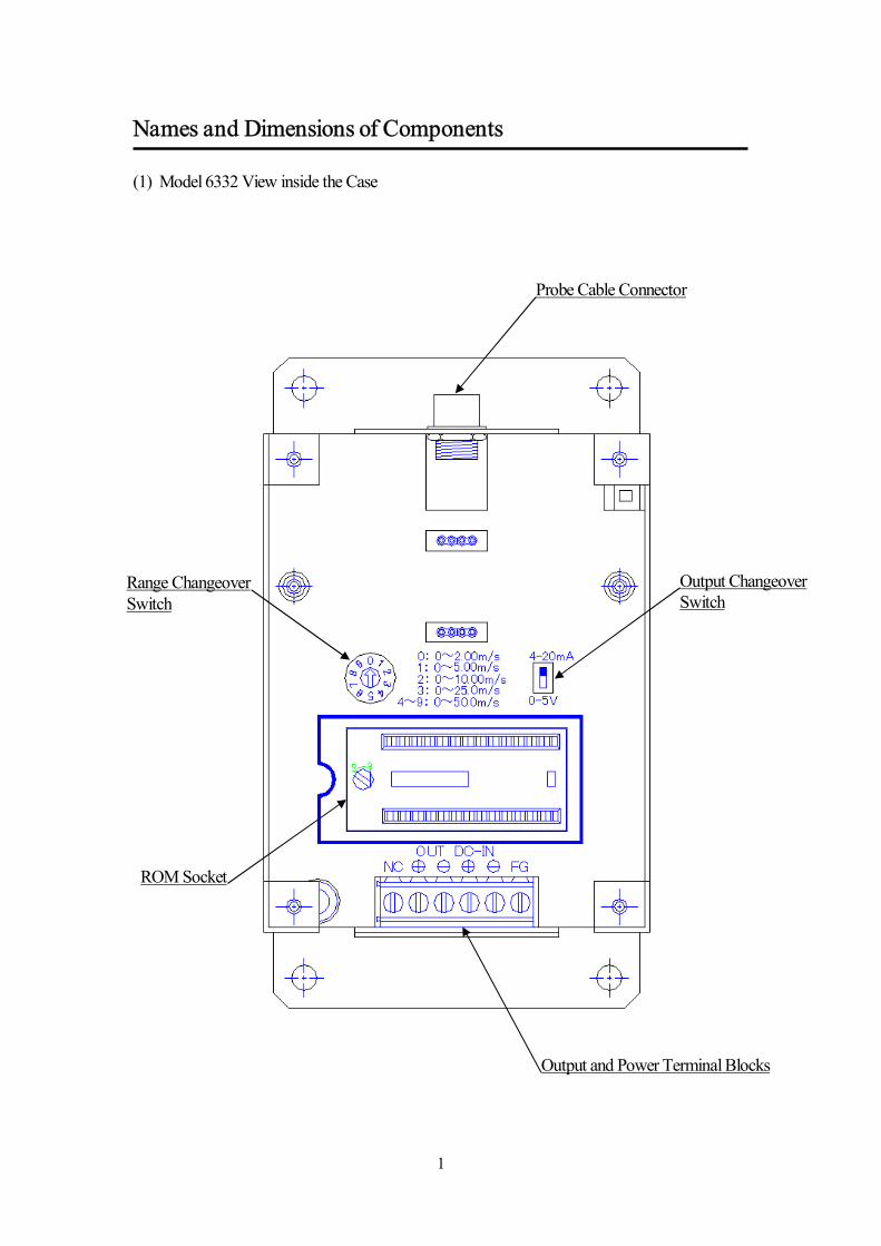
Names and Dimensions of Components (1) Model 6332 View inside the Case
Probe Cable Connector
Output Changeover Switch
Range Changeover Switch
ROM Socket
Output and Power Terminal Blocks
2
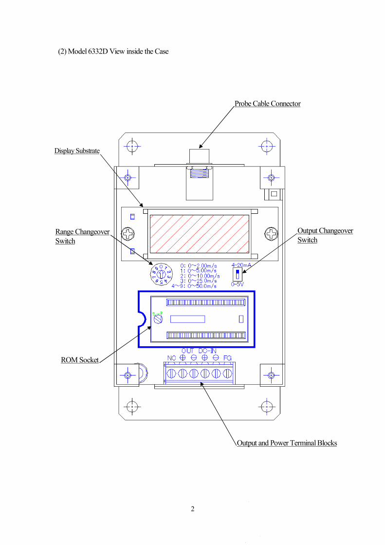
(2) Model 6332D View inside the Case
Probe Cable Connector
Output Changeover Switch
Range Changeover Switch
ROM Socket
Output and Power Terminal Blocks
Display Substrate
3
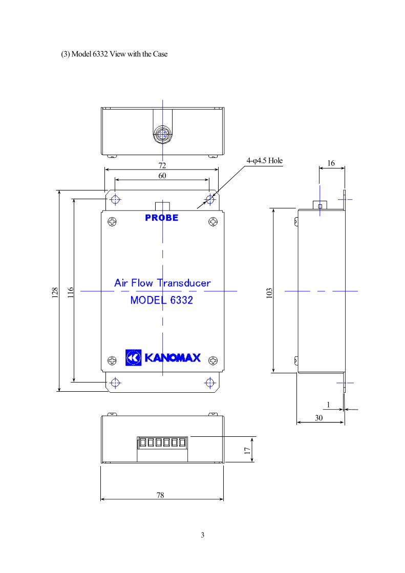
(3) Model 6332 View with the Case
72 60
128
116
78
17
103
16
1 30
4-φ4.5 Hole
4
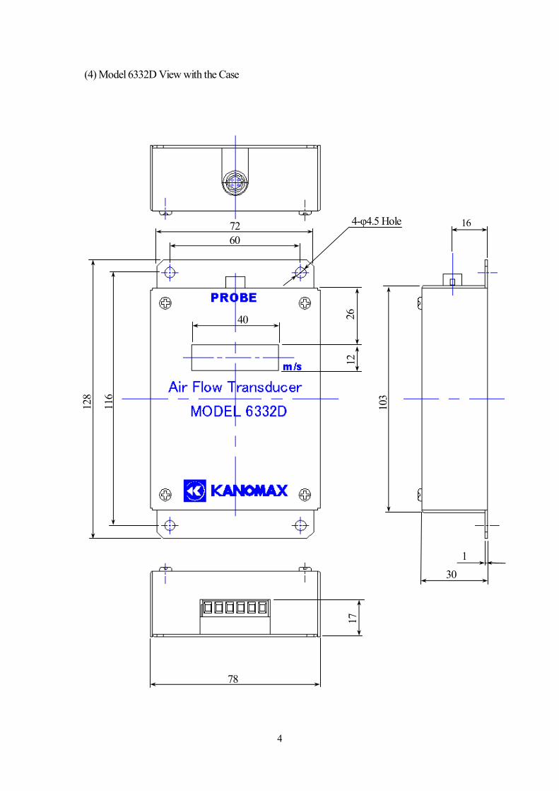
(4) Model 6332D View with the Case
72 60
128
116
78
17
103
16
1 30
4-φ4.5 Hole
12
26
40
5
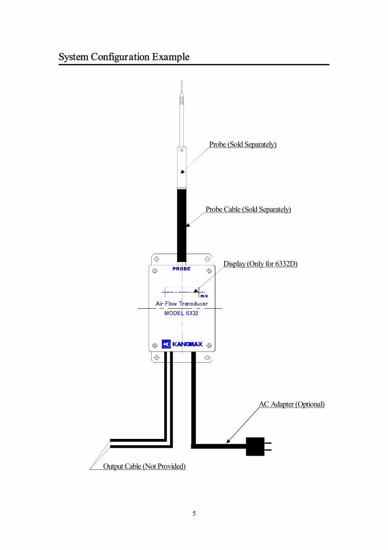
System Configuration Example
Probe (Sold Separately)
Probe Cable (Sold Separately)
Display (Only for 6332D)
AC Adapter (Optional)
Output Cable (Not Provided)
6
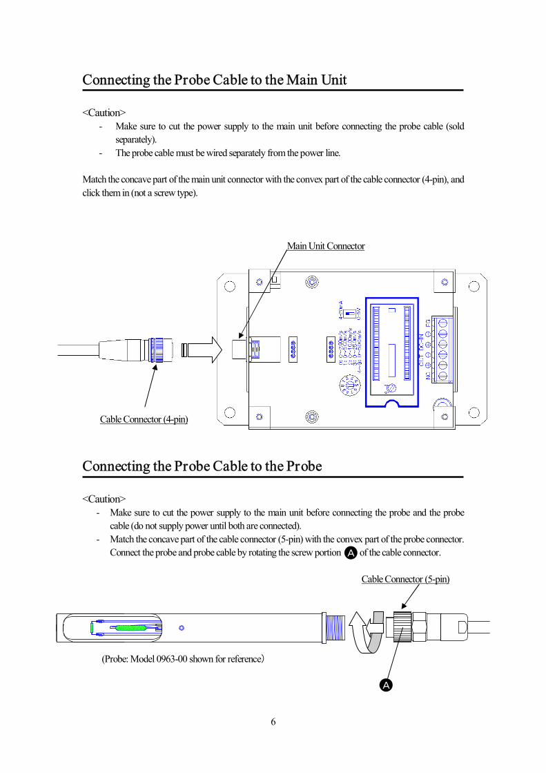
Connecting the Probe Cable to the Main Unit <Caution>
- Make sure to cut the power supply to the main unit before connecting the probe cable (sold separately).
- The probe cable must be wired separately from the power line.
Match the concave part of the main unit connector with the convex part of the cable connector (4-pin), and click them in (not a screw type).
Main Unit Connector Cable Connector (4-pin)
Connecting the Probe Cable to the Probe <Caution>
- Make sure to cut the power supply to the main unit before connecting the probe and the probe cable (do not supply power until both are connected).
- Match the concave part of the cable connector (5-pin) with the convex part of the probe connector. Connect the probe and probe cable by rotating the screw portion of the cable connector.
Cable Connector (5-pin)
(Probe: Model 0963-00 shown for reference)
A
A
7
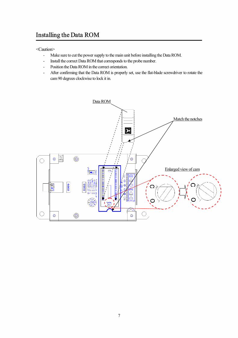
Installing the Data ROM <Caution>
- Make sure to cut the power supply to the main unit before installing the Data ROM. - Install the correct Data ROM that corresponds to the probe number. - Position the Data ROM in the correct orientation. - After confirming that the Data ROM is properly set, use the flat-blade screwdriver to rotate the
cam 90 degrees clockwise to lock it in.
Match the notches
Data ROM
Enlarged view of cam
8
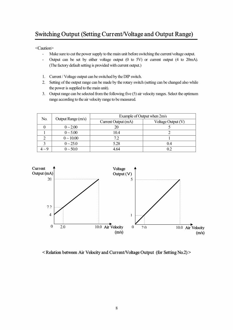
Switching Output (Setting Current/Voltage and Output Range) <Caution>
- Make sure to cut the power supply to the main unit before switching the current/voltage output. - Output can be set by either voltage output (0 to 5V) or current output (4 to 20mA).
(The factory default setting is provided with current output.)
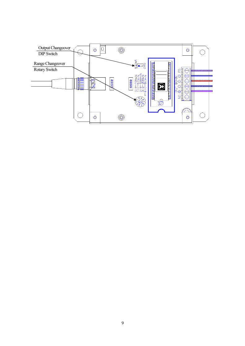
1. Current / Voltage output can be switched by the DIP switch. 2. Setting of the output range can be made by the rotary switch (setting can be changed also while
the power is supplied to the main unit). 3. Output range can be selected from the following five (5) air velocity ranges. Select the optimum
range according to the air velocity range to be measured.
Example of Output when 2m/s No. Output Range (m/s) Current Output (mA) Voltage Output (V) 0 0 ~ 2.00 20 5 1 0 ~ 5.00 10.4 2 2 0 ~ 10.00 7.2 1 3 0 ~ 25.0 5.28 0.4
4 ~ 9 0 ~ 50.0 4.64 0.2
4
20
0 10.0 2.0
7.2
Current Output (mA)
1
5
0 10.0 2.0 Air Velocity (m/s)
< Relation between Air Velocity and Current/Voltage Output (for Setting No.2) >
Voltage Output (V)
Air Velocity (m/s)
9
Output Changeover DIP Switch
Range Changeover Rotary Switch
10
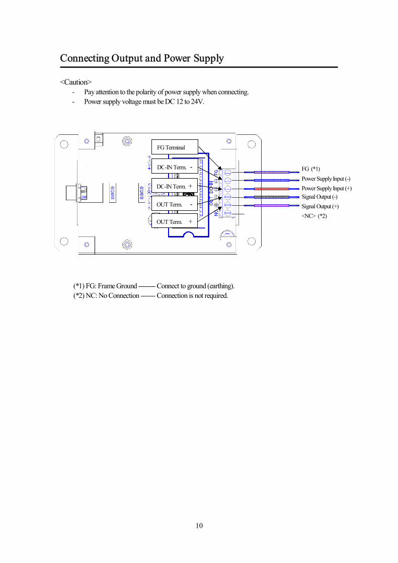
Connecting Output and Power Supply <Caution>
- Pay attention to the polarity of power supply when connecting. - Power supply voltage must be DC 12 to 24V.
(*1) FG: Frame Ground -------- Connect to ground (earthing). (*2) NC: No Connection ------- Connection is not required.
FG Terminal
DC-IN Term. -
DC-IN Term. +
OUT Term. -
FG (*1) Power Supply Input (-) Power Supply Input (+) Signal Output (-) Signal Output (+) <NC> (*2)
OUT Term. +
11
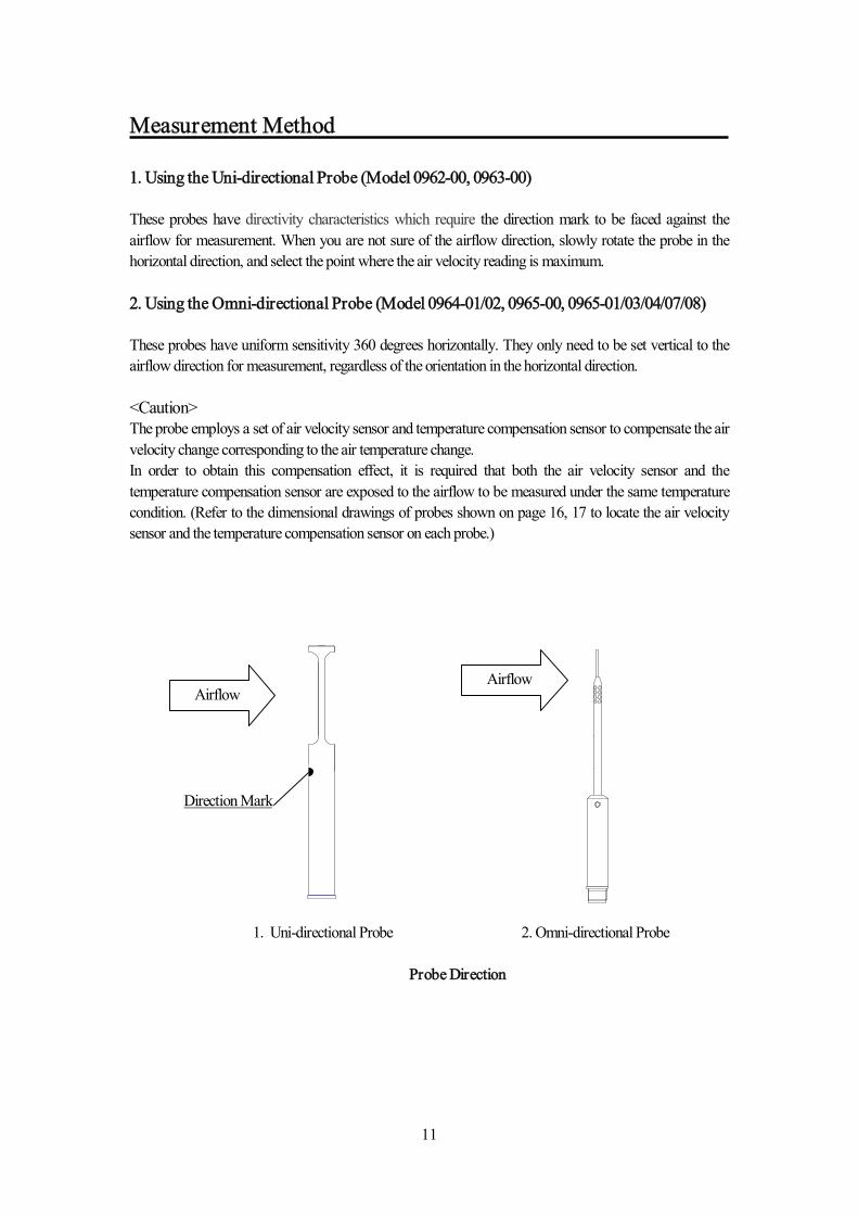
Measurement Method 1. Using the Uni-directional Probe (Model 0962-00, 0963-00) These probes have directivity characteristics which require the direction mark to be faced against the airflow for measurement. When you are not sure of the airflow direction, slowly rotate the probe in the horizontal direction, and select the point where the air velocity reading is maximum. 2. Using the Omni-directional Probe (Model 0964-01/02, 0965-00, 0965-01/03/04/07/08) These probes have uniform sensitivity 360 degrees horizontally. They only need to be set vertical to the airflow direction for measurement, regardless of the orientation in the horizontal direction. <Caution> The probe employs a set of air velocity sensor and temperature compensation sensor to compensate the air velocity change corresponding to the air temperature change. In order to obtain this compensation effect, it is required that both the air velocity sensor and the temperature compensation sensor are exposed to the airflow to be measured under the same temperature condition. (Refer to the dimensional drawings of probes shown on page 16, 17 to locate the air velocity sensor and the temperature compensation sensor on each probe.)
Airflow
Direction Mark
Airflow
1. Uni-directional Probe 2. Omni-directional Probe
Probe Direction
12
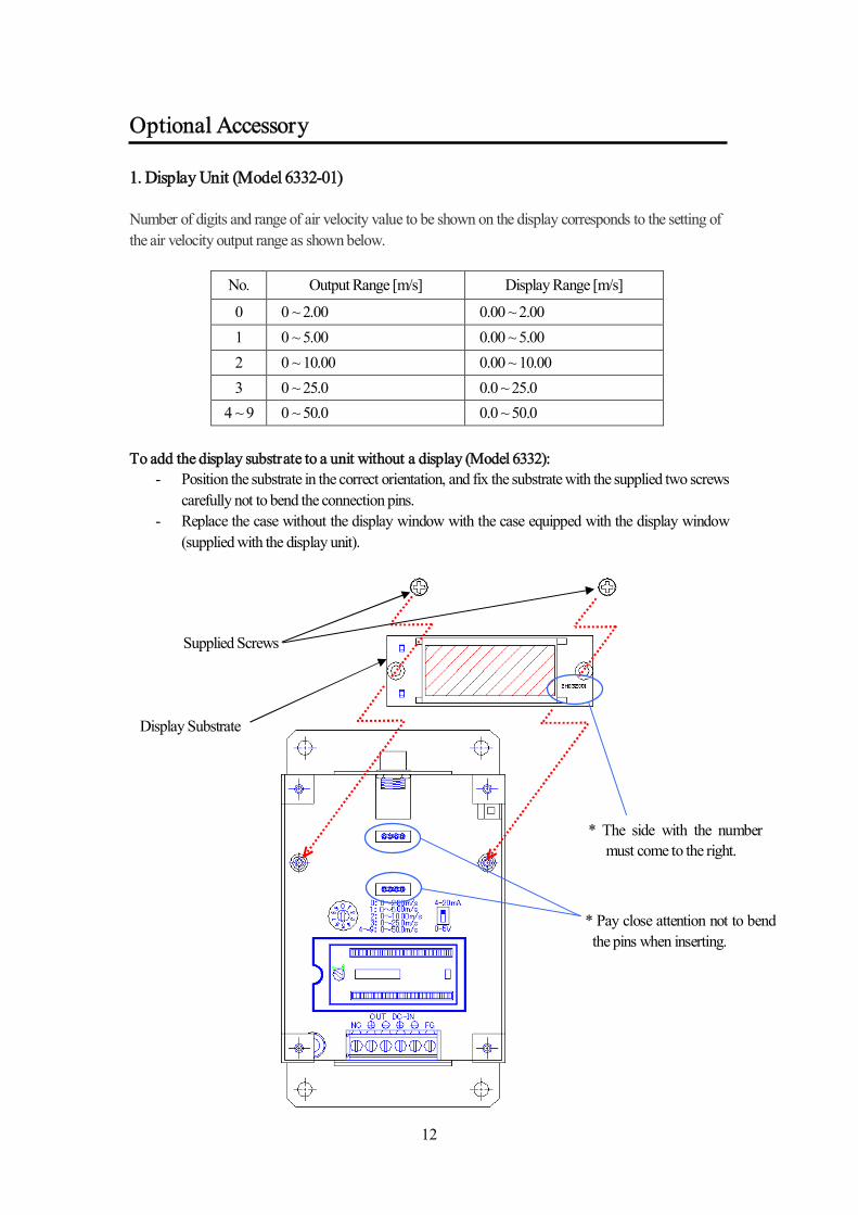
Optional Accessory 1. Display Unit (Model 6332-01) Number of digits and range of air velocity value to be shown on the display corresponds to the setting of the air velocity output range as shown below.
No. Output Range [m/s] Display Range [m/s]
0 0 ~ 2.00 0.00 ~ 2.00 1 0 ~ 5.00 0.00 ~ 5.00 2 0 ~ 10.00 0.00 ~ 10.00 3 0 ~ 25.0 0.0 ~ 25.0
4 ~ 9 0 ~ 50.0 0.0 ~ 50.0 To add the display substrate to a unit without a display (Model 6332):
- Position the substrate in the correct orientation, and fix the substrate with the supplied two screws carefully not to bend the connection pins.
- Replace the case without the display window with the case equipped with the display window (supplied with the display unit).
Supplied Screws
Display Substrate
* The side with the number must come to the right.
* Pay close attention not to bend the pins when inserting.
13
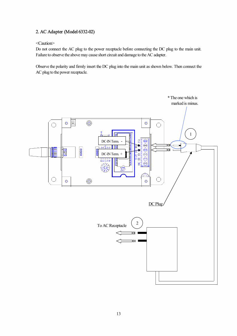
2. AC Adapter (Model 6332-02) <Caution> Do not connect the AC plug to the power receptacle before connecting the DC plug to the main unit. Failure to observe the above may cause short circuit and damage to the AC adapter. Observe the polarity and firmly insert the DC plug into the main unit as shown below. Then connect the AC plug to the power receptacle.
* The one which is marked is minus.
DC Plug
DC-IN Term. -
DC-IN Term. +
1
2 To AC Receptacle
14
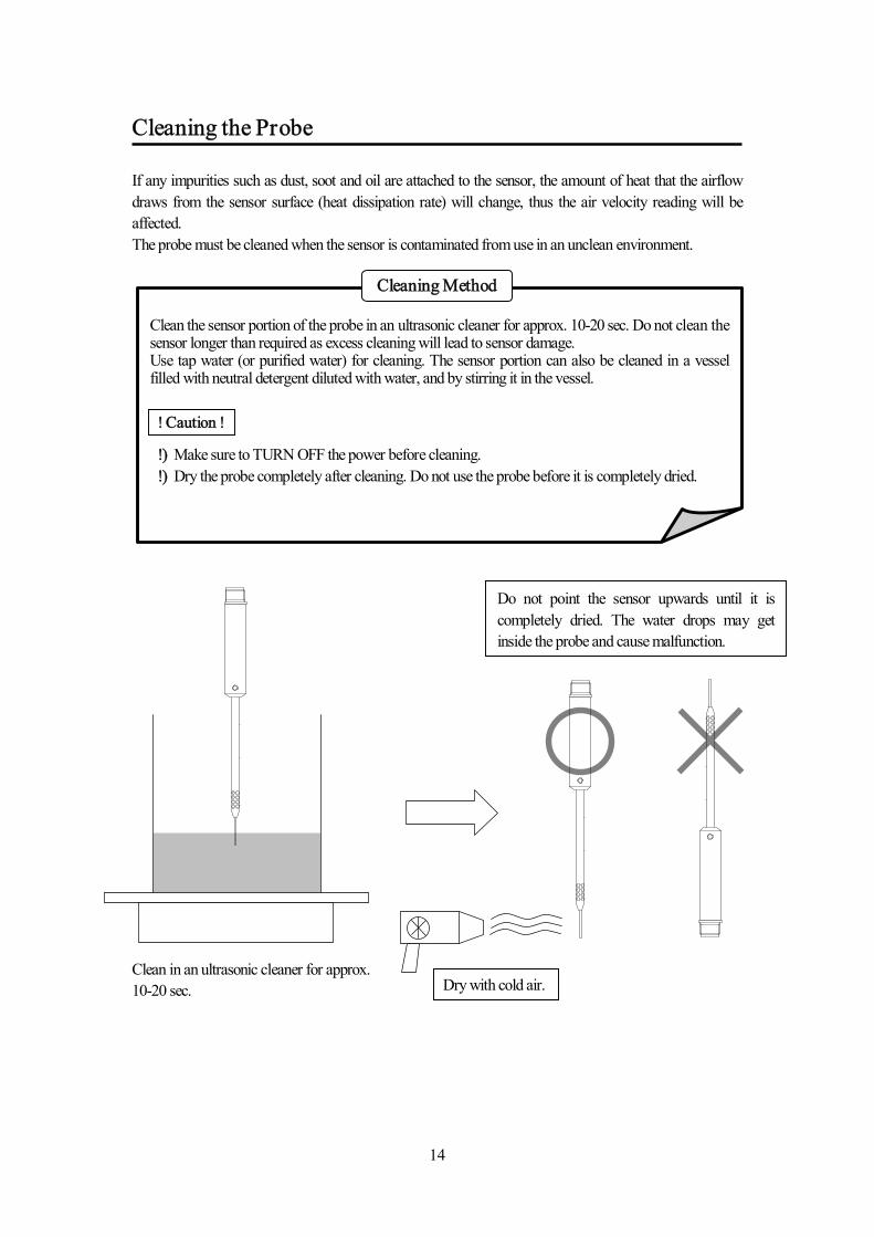
Cleaning the Probe If any impurities such as dust, soot and oil are attached to the sensor, the amount of heat that the airflow draws from the sensor surface (heat dissipation rate) will change, thus the air velocity reading will be affected. The probe must be cleaned when the sensor is contaminated from use in an unclean environment.
Clean the sensor portion of the probe in an ultrasonic cleaner for approx. 10-20 sec. Do not clean the sensor longer than required as excess cleaning will lead to sensor damage. Use tap water (or purified water) for cleaning. The sensor portion can also be cleaned in a vessel filled with neutral detergent diluted with water, and by stirring it in the vessel.
!) Make sure to TURN OFF the power before cleaning. !) Dry the probe completely after cleaning. Do not use the probe before it is completely dried.
Cleaning Method
Clean in an ultrasonic cleaner for approx. 10-20 sec.
Do not point the sensor upwards until it is completely dried. The water drops may get inside the probe and cause malfunction.
! Caution !
Dry with cold air.
15
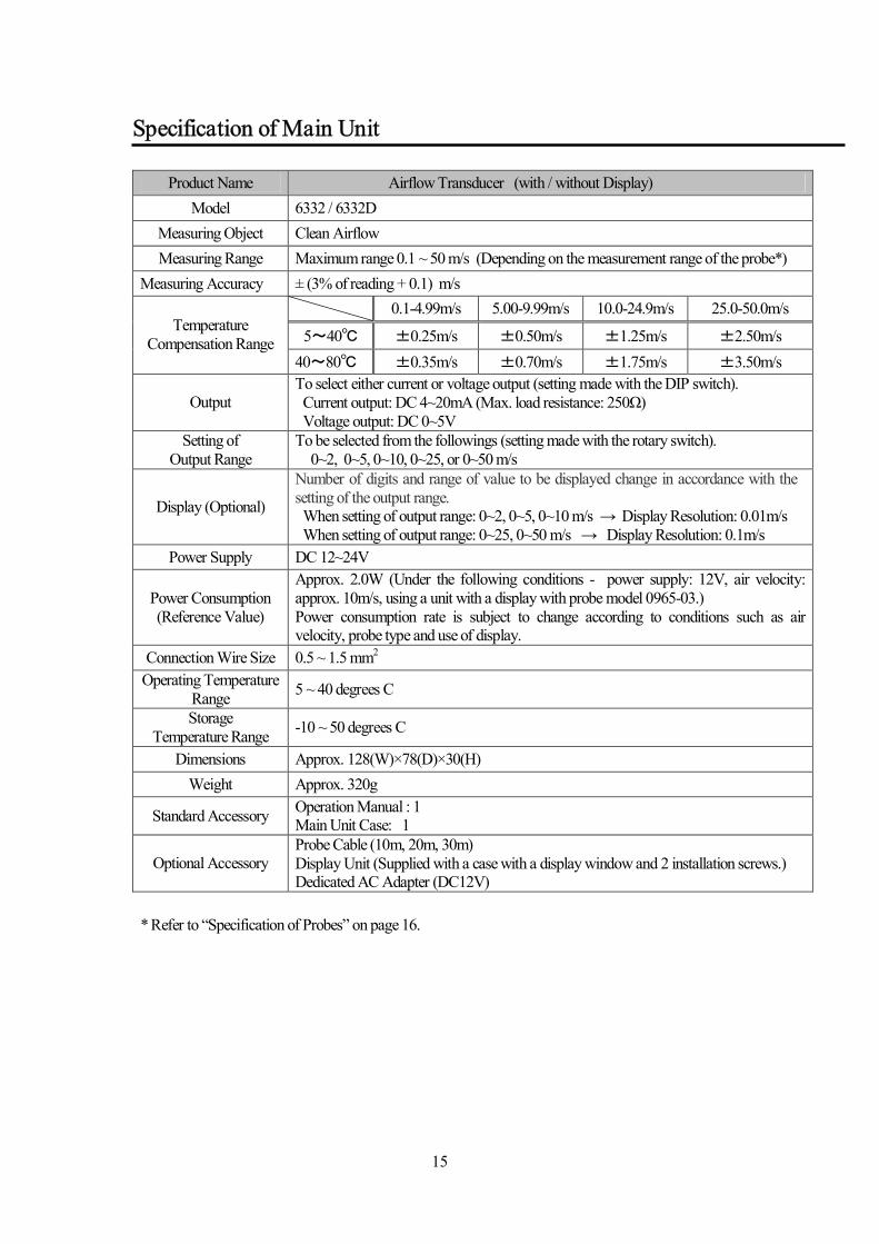
Specification of Main Unit
Product Name Airflow Transducer (with / without Display) Model 6332 / 6332D
Measuring Object Clean Airflow Measuring Range Maximum range 0.1 ~ 50 m/s (Depending on the measurement range of the probe*)
Measuring Accuracy ± (3% of reading + 0.1) m/s 0.1-4.99m/s 5.00-9.99m/s 10.0-24.9m/s 25.0-50.0m/s
5~40℃ ±0.25m/s ±0.50m/s ±1.25m/s ±2.50m/s Temperature
Compensation Range 40~80℃ ±0.35m/s ±0.70m/s ±1.75m/s ±3.50m/s
Output To select either current or voltage output (setting made with the DIP switch). Current output: DC 4~20mA (Max. load resistance: 250Ω) Voltage output: DC 0~5V
Setting of Output Range
To be selected from the followings (setting made with the rotary switch). 0~2, 0~5, 0~10, 0~25, or 0~50 m/s
Display (Optional)
Number of digits and range of value to be displayed change in accordance with the setting of the output range. When setting of output range: 0~2, 0~5, 0~10 m/s → Display Resolution: 0.01m/s When setting of output range: 0~25, 0~50 m/s → Display Resolution: 0.1m/s
Power Supply DC 12~24V
Power Consumption (Reference Value)
Approx. 2.0W (Under the following conditions - power supply: 12V, air velocity: approx. 10m/s, using a unit with a display with probe model 0965-03.) Power consumption rate is subject to change according to conditions such as air velocity, probe type and use of display.
Connection Wire Size 0.5 ~ 1.5 mm2 Operating Temperature
Range 5 ~ 40 degrees C
Storage Temperature Range -10 ~ 50 degrees C
Dimensions Approx. 128(W)×78(D)×30(H) Weight Approx. 320g
Standard Accessory Operation Manual : 1 Main Unit Case: 1
Optional Accessory Probe Cable (10m, 20m, 30m) Display Unit (Supplied with a case with a display window and 2 installation screws.) Dedicated AC Adapter (DC12V)
* Refer to “Specification of Probes” on page 16.
16
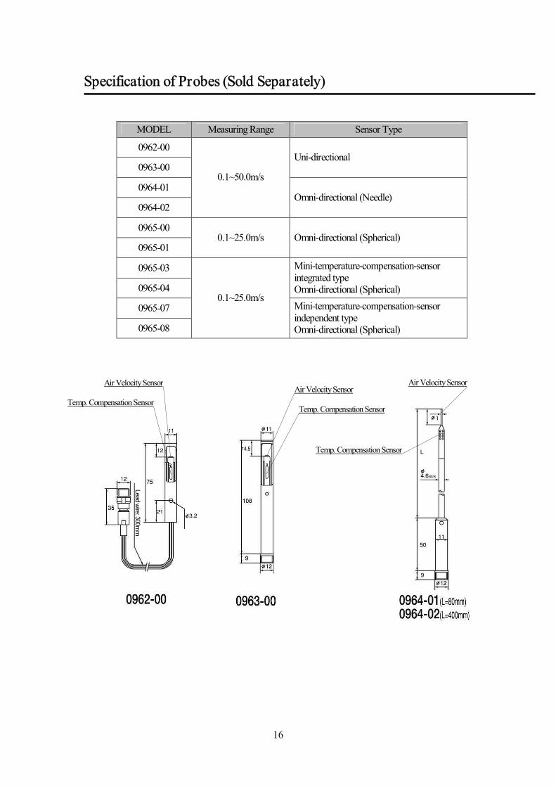
Specification of Probes (Sold Separately)
MODEL Measuring Range Sensor Type
0962-00
0963-00 Uni-directional
0964-01
0964-02
0.1~50.0m/s
Omni-directional (Needle)
0965-00
0965-01 0.1~25.0m/s Omni-directional (Spherical)
0965-03
0965-04
Mini-temperature-compensation-sensor integrated type Omni-directional (Spherical)
0965-07
0965-08
0.1~25.0m/s Mini-temperature-compensation-sensor independent type Omni-directional (Spherical)
Air Velocity Sensor
Temp. Compensation Sensor Air Velocity Sensor
Temp. Compensation Sensor seSensor
Lead wire: 300mm
Air Velocity Sensor
Temp. Compensation Sensor
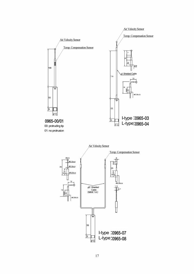
17
Air Velocity Sensor
Air Velocity Sensor
Temp. Compensation Sensor seSensor
Temp. Compensation Sensor
I-type L-type
I-type L-type
Shielded Cable
Shielded Cable
Air Velocity Sensor
Temp. Compensation Sensor
00: protruding tip 01: no protrusion
18
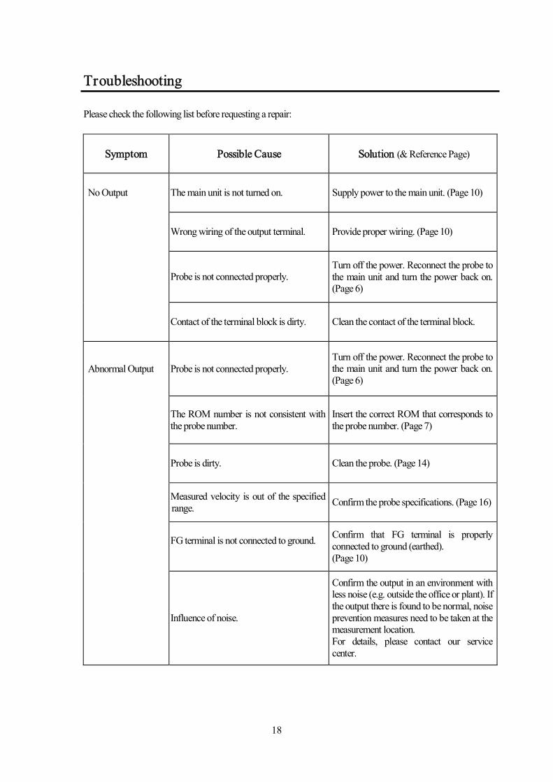
Troubleshooting Please check the following list before requesting a repair:
Symptom Possible Cause Solution (& Reference Page)
No Output The main unit is not turned on. Supply power to the main unit. (Page 10)
Wrong wiring of the output terminal. Provide proper wiring. (Page 10)
Probe is not connected properly. Turn off the power. Reconnect the probe to the main unit and turn the power back on. (Page 6)
Contact of the terminal block is dirty. Clean the contact of the terminal block.
Abnormal Output Probe is not connected properly. Turn off the power. Reconnect the probe to the main unit and turn the power back on. (Page 6)
The ROM number is not consistent with the probe number.
Insert the correct ROM that corresponds to the probe number. (Page 7)
Probe is dirty. Clean the probe. (Page 14)
Measured velocity is out of the specified range. Confirm the probe specifications. (Page 16)
FG terminal is not connected to ground.
Confirm that FG terminal is properly connected to ground (earthed). (Page 10)
Influence of noise.
Confirm the output in an environment with less noise (e.g. outside the office or plant). If the output there is found to be normal, noise prevention measures need to be taken at the measurement location. For details, please contact our service center.
19
Product Warranty and After Service
A warranty card is not included in this product.
This product is warranted against defects in materials and workmanship for a period of one year from the date of original purchase.
When you have a problem with your unit, please check out the “Troubleshooting” section (page 18)
first.
If that does not help, please contact your local distributor, or call our service center (See last page for contact information).
During the warranty period, we will repair at no charge a product that probes to be defective due to
material or workmanship under normal use. The limited warranty covers all defects encountered in normal use of the product, and does not apply in cases such as; loss or damage to the product due to abuse, mishandling, alternation, or natural disaster. All return shipping charges are the responsibility of the customer.
Repair after warranty expiration:
Upon request, we will repair the instrument at the customer’s expense, if the instrument’s performance is found to be recoverable by providing the repair.
Replacement parts are available for a minimum period of five (5) years after termination of
production. This storage period of replacement parts is considered as the period during which we can provide repair service. For further information, please contact our service center.
When making an inquiry, please provide the following information.
Please inform us: - Product Name: Air Transducer - Model Number: 6332 or 6332D - Serial Number: xxxxxx - Probe Model: Your Probe Model - Description of Symptom in detail. - Date of Purchase: Month / Year
After Service
Product Warranty
20
Contact Information
JAPAN KANOMAX JAPAN, INC. 2-1 Shimizu Suita City, Osaka 565-0805, Japan TEL: 81-6-6877-0183 FAX: 81-6-6879-5570 URL: http://www.kanomax.co.jp/ E-Mail: [email protected]
USA & EUROPE KANOMAX USA, INC. PO Box 372, 219 Route 206, Andover, NJ 07821 U.S.A. TEL: (800)-247-8887 / (973)-786-6386 FAX: (973)-786-7586 URL: http://www.kanomax-usa.com/ E-Mail: [email protected] CHINA
Shenyang Kano Scientific Instrument Co., Ltd No. 12, 4 Jia Wencui Road Heping District Shenyang City PRC TEL: 86-24-23845309 FAX: 86-24-23898417 URL: http://www.kanomax.com.cn/ E-mail: [email protected]