Embed Size (px)
Citation preview
Air Gauge Measurement and Driven Lap Polishingin the Production of Aspheric Surfaces
George Random and Edward P. Wallerstein
The increased demand for aspheric surfaces in optical systems has required refinements and advances inoptical shop technology. Air gauges have been used to measure aspheric surfaces in prepolished andpolished conditions to accuracies on the order of one wavelength of visible light. Small, synchronouslydriven laps have been used in the polishing and figuring of aspheric surfaces with good results regardingspeed, accuracy, and smoothness. Both techniques provide interesting possibilities for future develop-ment.
1. Introduction
The use of precision aspheric surfaces in optics hasbeen increasing rapidly in recent years. In addition tothe classical use of conic sections in astronomical instru-ments, and the use of the Schmidt corrector plate andits genre, aspherics have become more and more prev-alent in purely refracting systems, often on two or moresurfaces.
One area in which this has occurred is in the field ofaerial reconnaissance lenses. In the wake of improvedreconnaissance technology, similar advances in lensesfor information storage and processing have been neces-sary.
Of quite recent importance in the demand foraspherics are some of the system concepts made prac-tical with the advent of the laser. High precisioncylinders and high-numerical-aperture, single-element,aspherically corrected lenses are some of the results.
Thus, as the demand for improved performance fromphotooptical and other systems has increased, and asmodern computers have made practical the frequentsynthesis of multiple aspheric systems, the lens maker islikewise required to extend continuously his capa-bilities.
There is an old saying in optics: "If you can measureit, you can make it". In the manufacture of any butthe mildest of aspherics the optician is wedded to histest setup as much as he is to his polishing machine; herequires an analytic understanding of his testing tech-nique and of the geometry of the surface he is working.
Aspheric surfaces may be divided immediately intotwo categories: those which are rotationally symmetric,and those which are not. The first kind can be rotated
The authors are with Diffraction Limited, Inc., MiddlesexTurnpike, Bedford, Massachusetts 01730.
Received 26 May 1.965.
continuously during manufacture; the second cannot.The advantages of the axis of symmetry are so great thateven when only off-axis sections are required, the wholesurface is produced wherever practical. Actually, mostsurfaces used in optics have an axis of symmetry, al-though this may be oriented with respect to the surfacein such a way as to be inconvenient as a manufacturingaid. A good example of this is a section of a cylindricalsurface where a reciprocating technique rather thancontinuous rotation is usually the most practical.'
A very large class of aspheric surfaces satisfies anadditional condition, requiring that the axis of symmetrycoincides with a unique optical axis. These surfacessatisfy the equation x2 + y2
= f(z), where z lies alongthe optical axis.
Both the magnitude of the asphericity, and the natureof the plane curve generating the surface are of im-portance in considering the testing and manufacturingtechniques.
We have chosen to discuss in some detail one area ofmeasurement and one area of manufacturing. Both ofthese have undergone considerable development inrecent years, have been used with great success, and areopen to further extension and refinement.
II. Air Gauge Measurement of Aspheric Surfaces
When surfaces are more than a few waves aspheric, itis desirable to grind in the asphericity, since the removalof any real mass of material by polishing is exceedinglyslow.
The more accurate the prepolishing measurement,the closer to completion the surface can be brought toutilizing the efficiencies of grinding.
Air gauges that measure variations in distance can beused to measure, with high accuracy, the general con-tour of an optical surface without recourse to refraction
May 1966 / Vol. 5, No. 5 / APPLIED OPTICS 737
I
or reflection. Even on polished surfaces this is oftenuseful as a prelude or adjunct to optical testing.
The accuracy reached can be on the order of a frac-tion of a visible wavelength. The inherent drawbackin air gauging is that the useful range of measurementis an inverse function of the sensitivity. The air gaugereadout is by observation of the height of a small air-borne float in a tube with horizontal calibration markson it. The height of the float changes with variationsof air flow produced by small changes in the distance ofa physical object from a nozzle that produces a con-tinuous stream of air. The mean distance is quite closeto the nozzle.
Typically, the calibrations on the tube are spaced 6mm apart, and repeatability of measurement allowsinterpolation between them to an accuracy of aboutone fifth of a division. Changes in sensitivity are ac-complished by the substitution of tubes having differ-ent internal tapers.
The sensitivity of an air gauge is about 1/200 therange of measurement. Thus, with a sensitivity of 0.1u, or about one fifth of a green wavelength, the range is0.02 mm, or an aspheric of this departure from amean sphere; with a sensitivity of one wavelength, theaspheric deviation may be 0.1 mm. The maximumrange for air gauges of the type we have been using isabout 0.2 mm.
Assuming that the range required gives the desiredaccuracy, the instrumentation is not completed simplyby possession of the air gauge; it is necessary to providea reference radius (or plane) from which the measure-ments can be made.
Several setups have been made, for both concave andconvex surfaces, to utilize this technique. The mainconsiderations in designing a mechanical radius, inorder to make sure that it will remain constant duringits scan across a surface, are stiffness and/or support,thermal stability, and the bearing forming the center ofrotation.
One particularly interesting set of optics on whichthis technique was used was the Kanigen coated beryl-lium primary and spectrometer mirrors for the NASAGoddard Space Flight Center Orbiting AstronomicalObservatory.2-5 In this case, the primarymirrorwas 1m in diam with a mean radius of about 3 m, and thespectrometer mirror was 0.6 m diam with a mean radiusof approximately 2 m. Both were rotationally sym-metrical about the optical axis; the aspheric deviationswere approximately 0.06 mm and 0.04 mm, respec-tively, from the mean radius.
The readout during a scan is accomplished by follow-ing the air gauge float with a pen attached to a chartrecorder. The speed of the scan and the speed of thechart must, of course, be properly synchronized. Atpresent, the recording is done manually; however,various schemes are possible for automatic readoutdevices.
After the scan, the readout from the chart is com-pared to a properly scaled graph of the aspheric devia-tion vs height on the surface. The optician can see
immediately from this where the material is and howmuch remains to be removed.
The abscissa scale can be arbitrary, and set for con-venience. In the usual setup, the ordinate scale isdirectly related to the amplification ratio of the airgauge tube being used. In the case of a tube with a0.1 mm range, the amplification is 2500: 1.
In practice, each scan is across a full meridian, andmore than one meridian is tested, to check for sym-metry.
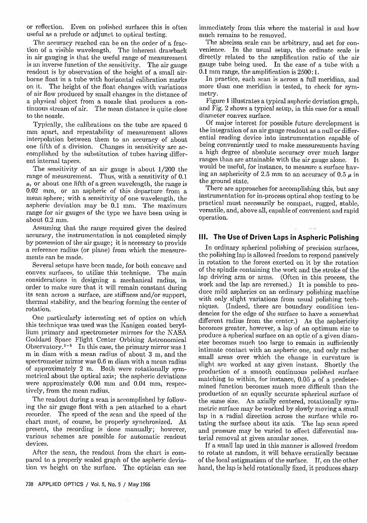
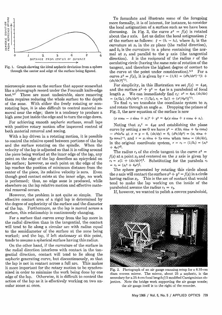
Figure 1 illustrates a typical aspheric deviation graph,and Fig. 2 shows a typical setup, in this case for a smalldiameter convex surface.
Of major interest for possible future development isthe integration of an air gauge readout as a null or differ-ential reading device into instrumentation capable ofbeing conveniently used to make measurements havinga high degree of absolute accuracy over much largerranges than are attainable with the air gauge alone. Itwould be useful, for instance, to measure a surface hav-ing an asphericity of 2.5 mm to an accuracy of 0.5 g inthe ground state.
There are approaches for accomplishing this, but anyinstrumentation for in-process optical shop testing to bepractical must necessarily be compact, rugged, stable,versatile, and, above all, capable of convenient and rapidoperation.
111. The Use of Driven Laps in Aspheric Polishing
In ordinary spherical polishing of precision surfaces,the polishing lap is allowed freedom to respond passivelyin rotation to the forces exerted on it by the rotationof the spindle containing the work and the stroke of thelap driving arm or arms. (Often in this process, thework and the lap are reversed.) It is possible to pro-duce mild aspherics on an ordinary polishing machinewith only slight variations from usual polishing tech-niques. (Indeed, there are boundary condition ten-dencies for the edge of the surface to have a somewhatdifferent radius from the center.) As the asphericitybecomes greater, however, a lap of an optimum size toproduce a spherical surface on an optic of a given diam-eter becomes much too large to remain in sufficientlyintimate contact with an aspheric one, and only rathersmall areas over which the change in curvature isslight are worked at any given instant. Shortly theproduction of a smooth continuous polished surfacematching to within, for instance, 0.05 ,u of a predeter-mined function becomes much more difficult than theproduction of an equally accurate spherical surface ofthe same size. An axially centered, rotationally sym-metric surface may be worked by slowly moving a smalllap in a radial direction across the surface while ro-tating the surface about its axis. The lap scan speedand pressure may be varied to effect differential ma-terial removal at given annular zones.
If a small lap used in this manner is allowed freedomto rotate at random, it will behave erratically becauseof the local astigmatism of the surface. If, on the otherhand, the lap is held rotationally fixed, it produces sharp
738 APPLIED OPTICS / Vol. 5, No. 5 / May 1966
IO X,
0o
I -
gL 7
en iU .
0 s6i 2 3 FDISTANCE FROM~ cENr ER. OF~ 5t12FACE
Fig. 1. Graph showing the ideal aspheric deviation from a spherethrough the center and edge of the surface being figured.
microscopic zones on the surface that appear somewhatlike a phonograph record under the Foucault knife-edgetest.6' 7 These are most undesirable, since removingthem requires reducing the whole surface to the depthof the zone. With either the freely rotating or non-rotating laps, it is also difficult to control material re-moval near the edge; there is a tendency to produce ahigh zone just inside the edge and to turn the edge down.
For achieving smooth aspheric surfaces, small lapswith positive rotary motion offer improved control ofboth material removal and zoning.
With a lap driven in a rotating motion, it is possibleto control the relative speed between portions of the lapand the surface rotating on the spindle. When thevelocity of the lap is adjusted so that it is rolling aroundthe piece being worked at the inner edge of the lap, anypoint on the edge of the lap describes an epicycloid onthe surface; however, as each point on the edge of thelap reaches the position of minimum distance from thecenter of the piece, its relative velocity is zero. Eventhough good contact exists at the inner edge, no workis performed; thus, no edge zone is produced, whileelsewhere on the lap relative motion and effective mate-rial removal occurs.
However, the problem is not quite so simple. Theeffective contact area of a rigid lap is determined bythe degree of asphericity of the surface and the diameterof the lap. Furthermore, as the lap is moved across asurface, this relationship is continuously changing.
For a surface that curves away from the lap more inthe radial direction than in the tangential, the contactwill tend to lie along a circular arc with radius equalto the semidiameter of the surface at the zone beingworked; and the lap, if left stationary at this point,tends to assume a spherical surface having this radius.
On the other hand, if the curvature of the surface inthe radial direction interferes with contact in the tan-gential direction, contact will tend to lie along theaspheric generating curve, but discontinuously, so thatthe lap is not in contact across a full arc. This makesit more important for the rotary motion to be synchro-nized in order to minimize the work being done by oneedge of the lap. Otherwise, it is difficult to control theaction of the lap as it is effectively working on two an-nular zones at once.
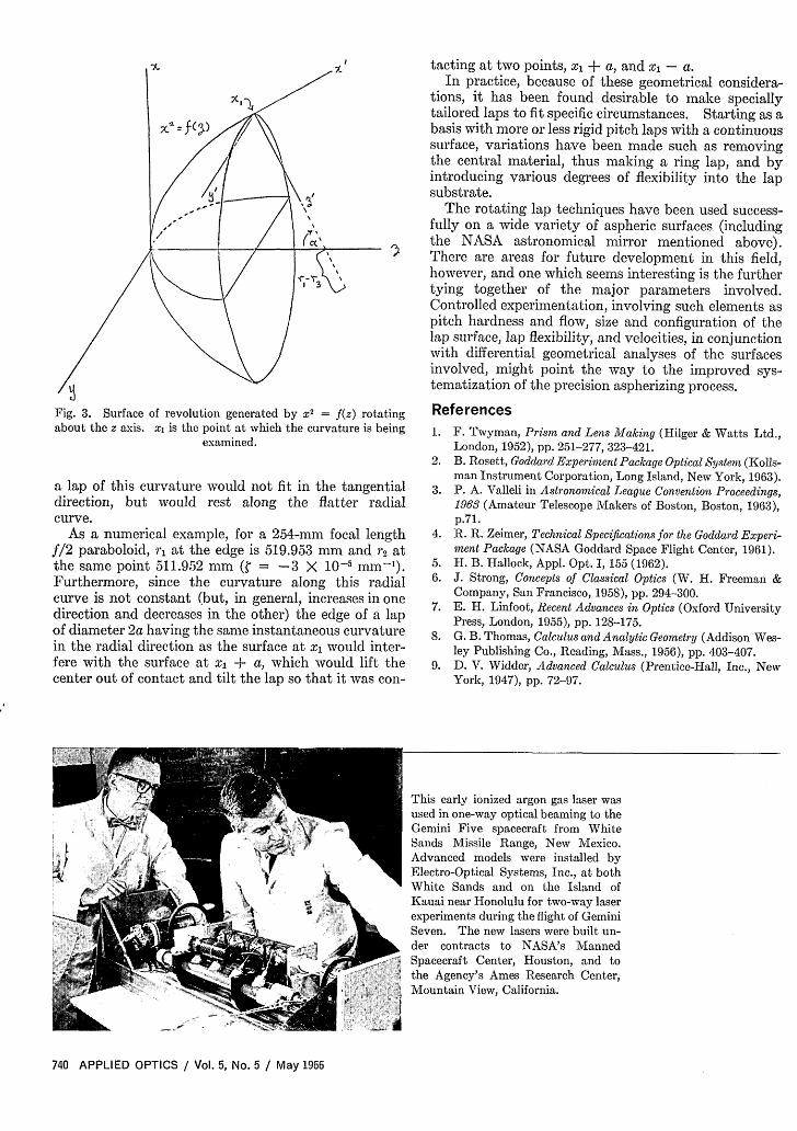
To formulate and illustrate some of the foregoingmore formally, it is of interest, for instance, to considerthe local astigmatism of a surface such as we have beendiscussing. In Fig. 3, the curve x2 = f(z) is rotatedabout the z axis. Let us define the local astigmatism rof the surface as follows: = - (k - kc2), where k1i is thecurvature at xi in the xz plane (the radial direction),and k 2 is the curvature in a plane containing the nor-mal at x1 and parallel to the y axis (the tangentialdirection). kc is the reciprocal of the radius r of theosculating circle (having the same rate of rotation of thetangent, and therefore the highest degree of contact tothe curve at the point under consideration).8 9 For acurve x2
- f(z), it is given by r = (1/k) = (d2z/dx2)-l[1 +(dz/dx)2]/2
For simplicity, in this illustration we set f(z) = 4pz,and the surface X
2 + y 2= 4pz is a paraboloid of focal
length p. We can immediately find ri: x2= 4pz, (dz/dX)
= (x/2p), (d'z/dx') = (1/ 2 p), r1 = 2p[l + (X2/4p2)J3/2.
To find r2 we translate the coordinate system to x1and rotate through an angle a. Dropping the primes ofFig. 3, the new equation of the surface is now
(x cosa - z since + X)2 + y 2 = 4p(x since + z cosa + z).
Noting that x12
= 4pz and establishing the planecurve by setting x 0 we have y
2= z(2x since + 4 p cosc)
- z2sin la at x = = 0, (dz/dy) = 0, (d2z/dy2) = (xi sina +2 p cosa)-1, and r = xi sinc + 2 p cosce when tana = (dz/dx),in the original coordinate system, r = r = (1/k 2 ) = (XI2
+ 4p)21.
The radius r3 of the circle tangent to the curve x2=f(z) at a point x1 and centered on the z axis is given byr3 = x[1 + (dx/dz)Y]1. Substituting for the parabola r3= r2 = (2 + 4p2)i.
The sphere generated by rotating this circle aboutthe z axis will contact the surface X
2+ y 2
= f(z) in a circlehaving radius x1. This is the arc of contact that wouldtend to make the lap working on the inside of theparaboloid assume the radius r2 = r3.
If, however, we wanted to polish a convex paraboloid,
Fig. 2. Photograph of an air gauge scanning setup for a 6.35-cmdiam convex mirror. The mirror, about 25 b& aspheric, is thesecondary for a 25.4-cm focal lengthf/2 modified Cassigrainian ob-jective. Note the bridge work supporting the air gauge nozzle;
the air gauge itself is to the right of the recorder.
May 1966 / Vol. 5, No. 5 / APPLIED OPTICS 739
tacting at two points, xi + a, and xi - a.In practice, because of these geometrical considera-
tions, it has been found desirable to make speciallytailored laps to fit specific circumstances. Starting as abasis with more or less rigid pitch laps with a continuoussurface, variations have been made such as removingthe central material, thus making a ring lap, and byintroducing various degrees of flexibility into the lapsubstrate.
The rotating lap techniques have been used success-fully on a wide variety of aspheric surfaces (includingthe NASA astronomical mirror mentioned above).There are areas for future development in this field,however, and one which seems interesting is the furthertying together of the major parameters involved.Controlled experimentation, involving such elements aspitch hardness and flow, size and configuration of thelap surface, lap flexibility, and velocities, in conjunctionwith differential geometrical analyses of the surfacesinvolved, might point the way to the improved sys-tematization of the precision aspherizing process.
Fig. 3. Surface of revolution generated by x2 = f(z) rotatingabout the z axis. x is the point at which the curvature is being
examined.
a lap of this curvature would not fit in the tangentialdirection, but would rest along the flatter radialcurve.
As a numerical example, for a 254-mm focal lengthf/2 paraboloid, r at the edge is 519.953 mm and 2 atthe same point 511.952 mm ( = -3 X 10⁻⁵ mm-').Furthermore, since the curvature along this radialcurve is not constant (but, in general, increases in onedirection and decreases in the other) the edge of a lapof diameter 2a having the same instantaneous curvaturein the radial direction as the surface at xi would inter-fere with the surface at x + a, which would lift thecenter out of contact and tilt the lap so that it was con-
References1. F. Twyman, Prism and Lens Making (Hilger & Watts Ltd.,
London, 1952), pp. 251-277, 323-421.2. B. Rosett, Goddard Experiment Package Optical System (Kolls-
man Instrument Corporation, Long Island, New York, 1963).3. P. A. Valleli in Astronomical League Convention Proceedings,
1963 (Amateur Telescope Makers of Boston, Boston, 1963),p.71.
4. R. R. Zeimer, Technical Specifications for the Goddard Experi-ment Package (NASA Goddard Space Flight Center, 1961).
5. H. B. Hallock, Appl. Opt. 1, 155 (1962).6. J. Strong, Concepts of Classical Optics (W. H. Freeman &
Company, San Francisco, 1958), pp. 294-300.7. E. H. Linfoot, Recent Advances in Optics (Oxford University
Press, London, 1955), pp. 128-175.8. G. B. Thomas, Calculus and Analytic Geometry (Addison Wes-
ley Publishing Co., Reading, Mass., 1956), pp. 403-407.9. D. V. Widder, Advanced Calculus (Prentice-Hall, Inc., New
York, 1947), pp. 72-97.
This early ionized argon gas laser wasused in one-way optical beaming to theGemini Five spacecraft from WhiteSands Missile Range, New Mexico.Advanced models were installed byElectro-Optical Systems, Inc., at bothWhite Sands and on the Island ofKauai near Honolulu for two-way laserexperiments during the flight of GeminiSeven. The new lasers were built un-der contracts to NASA's MannedSpacecraft Center, Houston, and tothe Agency's Ames Research Center,Mountain View, California.
740 APPLIED OPTICS / Vol. 5, No. 5 / May 1966
XI
3'