Embed Size (px)
Citation preview
Air heater KW2.0 5.0 Manual
IntroductionApplication field of Air heater
The air heater is not affected by the engine ,and it issupplied for the following vehicles with corresponding power. All kinds of auto and trailers. Construction machinery Agricultural machinery Boat, ship, yacht Caravan
Function Warm-up, defrost glass Heat and keep warm for the followed area:
---Driving cab, cabin---Cargo hold---Interior of staff carrier---Caravan
The heater can not be used on followed place andsituation Constant heating for long time:
---Living room, garage---Residential purpose boat
Heat and dry:---Life(people, animal), blowing hot air directly---Articles and objects---Blow hot air to container
Heater Safety instruction of installation and operation
Installation
Prevent the substances around heater from being damaged
and influenced by high temperature.
Exhaust emission systemWhen put the exhaust vent, prevent the exhaust entering
the heating space through ventilator, hot air inlet and window.
Keep the exhaust pipe clear. The exhaust pipe outlet shall be
kept away from anything flammable, and avoid heating and
igniting the flammable goods and loading cargo on the ground.
The air inlet of combustion-supporting airThe combustion-supporting air which is used for heater
burning shall not be inhaled from passenger compartment. The
air inlet shall not be blocked, and keep the inlet open and clear.
If the air inlet equipped with filter, keep the filter clean
regularly.
The heating air inletThe heater air shall be composed by fresh air or
circulating air, which is inhaled from clean area. The air inlet
pipe shall be protected by safety fence or other suitable tools,
and keep the pipe clear and open.
The heating air outletIn order to prevent the people and goods from being
damaged, the hot air pipe shall be installed in the place where it
could not be access to easily.
Safety instruction Following measures shall not be adopted
---Change the important component of heater
---Make use of the spare parts from other manufacturers
without permission
---Disobey the instruction and guide during installation or
operation
Only allow using original attachment and spare parts
during installation and maintenance
The heaters shall not be used in the places where may form
flammable vapor or dust, for example:
---Fuel depot
---Carbon storehouse
---Timber storehouse
---Granary and similar sites
---Diesel/petrol station
The heaters shall be turned off when fill fuel
If the fuel leak or discharge from the fuel system of heaters,
please contact with the service provider to repair
In the process of work, it is forbidden to cut off the electric
power directly to stop the heater working
Product
SurveyKW2.0 Air heater (hereinafter referred to as the heater) is
independent to the original engine system, it makes use of 12Vor 24V direct current to drive. There are two kinds of controlmode of the heater: Automatic control mode and Manualcontrol mode. The heater adopts light diesel and gasolinewhich corresponds to the environmental temperature as fuel,and it can be started and operated normally at the temperatureof above -40℃ . The inhaled fresh air is heated to hot airthrough heat exchanger by the energy which comes from fuelburning, then blown to where it is needed. This type of heaterowns the advantage of compact structure, light weight, highthermal efficiency, economize on electricity and fuel, easyinstallation.
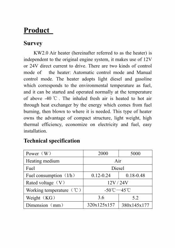
Technical specification
Power(W) 2000 5000Heating medium AirFuel DieselFuel consumption(l/h) 0.12-0.24 0.18-0.48Rated voltage(V) 12V / 24VWorking temperature(℃) -50℃—45℃Weight(KG) 3.6
5.25.2
Dimension(mm) 320x125x157 380x145x177
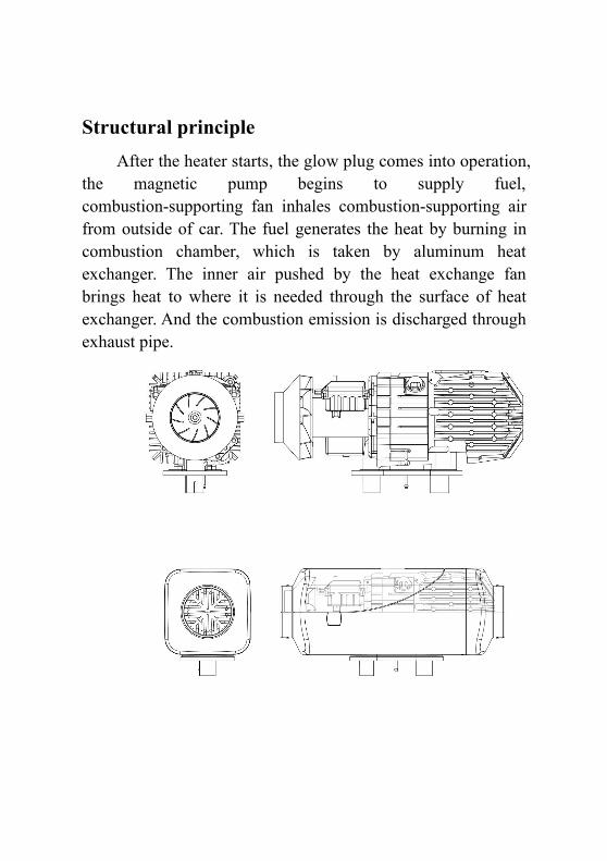
Structural principleAfter the heater starts, the glow plug comes into operation,
the magnetic pump begins to supply fuel,combustion-supporting fan inhales combustion-supporting airfrom outside of car. The fuel generates the heat by burning incombustion chamber, which is taken by aluminum heatexchanger. The inner air pushed by the heat exchange fanbrings heat to where it is needed through the surface of heatexchanger. And the combustion emission is discharged throughexhaust pipe.
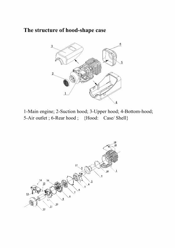
The structure of hood-shape case
1-Main engine; 2-Suction hood; 3-Upper hood; 4-Bottom-hood;5-Air outlet ; 6-Rear hood ; {Hood: Case/ Shell}
1.Exhaust tube 2.Combustion pipe 3.Combustor 4.Fuel tube 5.Air inlet
distributer 6.Gasket 7.Combustion supporting fan blades 8.Bracket of
fan motor 9.Gasket 10.Combustion supporting air inlet 11.Fan motor
12. Blade wheel of heating fan 13.Main control panel 14.Fixing screw
15.Fixing screw 16.Fixing screw 17.ignitor 18.heat sensor
19. Sensor Fixed bracket
InstallationOnly special-purpose parts can be used for installation ofthe heater. Following picture is the diagram for installation.The positions and ways of fixing of various parts may varyfrom one automobile model to another, but the generalprinciples must be followed in conformity with therequirements of this chapter. Otherwise the heater may notwork normally or safety problems my occur.
Main heater installationThe main heater could be installed both inside and outside
of the vehicle. If the heater is installed outside the vehicle,measures must be taken to avoid splashing water onto theheater. Enough space must be provided for installation for theconvenience of heating air flow and installation,maintenance ofthe main heater.
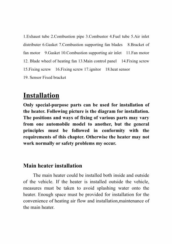
Good sealing is necessary between the main heater andthe installation surface on the vehicle.The special gasketsupplied by the manufacturer must inserted in.And theinstallation surface must be even.Its parts at the installationbases of the main heater should have uneveness lessthan1mm.After drilling installation holes, eveness must beimproved according to this requirement.At installation, pleaserotate the four M6 nuts tight, which are provided by themanufacturer.
For re-installation of the main heater, a new gasket mustbe used to replace the old one.
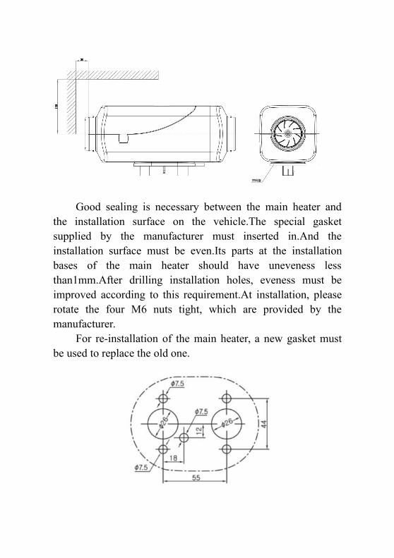
Attention must be paid to that the inclination angle shallnot exceed the limit, or normal operation will be affected.Direction for installation of the main heater is shown in thefollowing picture.
After installation of the main heater,please check andmake sure that there is no contact or friction between the bladewheel of fan and other nearby parts to avoid unsmoothoperation.
Installation of Air Heating SystemThe air heating system of the heater should not be
connected with the air channel of the vehicle.Eitherindependent outer circulation or inner circulation mode can beadopted.
When an external heating air tube is attached to the heater,the tube diameter should not be smaller than 85mm.Its materialshould be capable to resist temperature of 130℃。The maximum pressure drop between the air inlet side andoutlet side of the air heating system should not be higher than
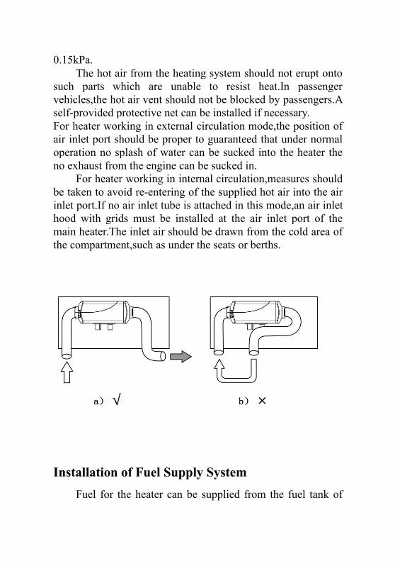
0.15kPa.The hot air from the heating system should not erupt onto
such parts which are unable to resist heat.In passengervehicles,the hot air vent should not be blocked by passengers.Aself-provided protective net can be installed if necessary.For heater working in external circulation mode,the position ofair inlet port should be proper to guaranteed that under normaloperation no splash of water can be sucked into the heater theno exhaust from the engine can be sucked in.
For heater working in internal circulation,measures shouldbe taken to avoid re-entering of the supplied hot air into the airinlet port.If no air inlet tube is attached in this mode,an air inlethood with grids must be installed at the air inlet port of themain heater.The inlet air should be drawn from the cold area ofthe compartment,such as under the seats or berths.
Installation of Fuel Supply SystemFuel for the heater can be supplied from the fuel tank of
the vehicle or an additional independent fuel tank. It is notallowed to install the fuel tank in the cab or passengercompartment or any region that is possibly to cause fire if anindependent fuel tank is used.
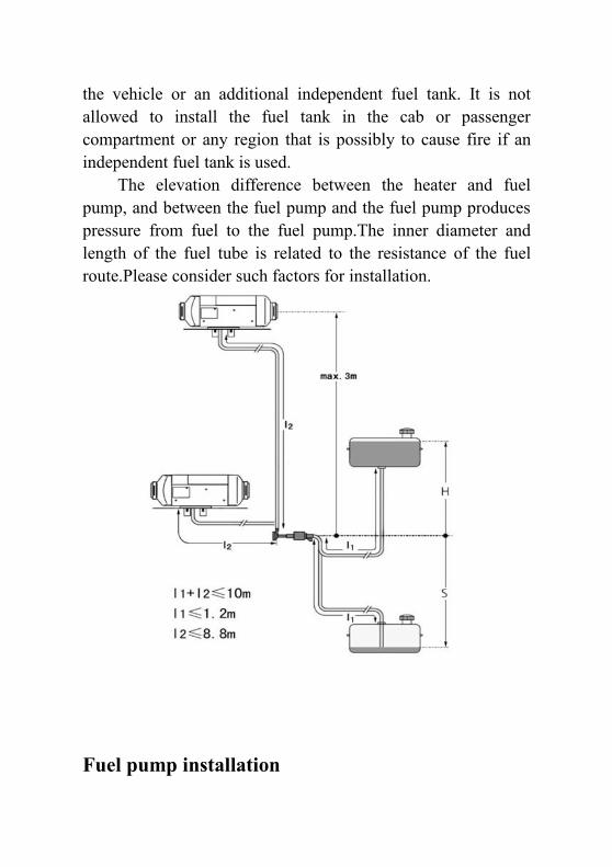
The elevation difference between the heater and fuelpump, and between the fuel pump and the fuel pump producespressure from fuel to the fuel pump.The inner diameter andlength of the fuel tube is related to the resistance of the fuelroute.Please consider such factors for installation.
Fuel pump installation
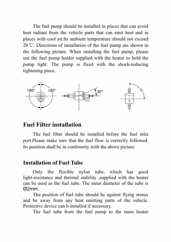
The fuel pump should be installed in places that can avoidheat radiant from the vehicle parts that can emit heat and inplaces with cool air.Its ambient temperature should not exceed20℃. Directions of installation of the fuel pump are shown inthe following picture. When installing the fuel pump, pleaseuse the fuel pump holder supplied with the heater to hold thepump tight. The pump is fixed with the shock-reducingtightening piece.
Fuel Filter installationThe fuel filter should be installed before the fuel inlet
port.Please make sure that the fuel flow is correctly followed.Its position shall be in conformity with the above picture.
Installation of Fuel TubeOnly the flexible nylon tube, which has good
light-resistance and thermal stability ,supplied with the heatercan be used as the fuel tube. The inner diameter of the tube isØ2mm.
The position of fuel tube should be against flying stonesand be away from any heat emitting parts of the vehicle.Protective device can b installed if necessary.
The fuel tube from the fuel pump to the main heater
should be in any directions other than downward direction. Thefuel tube shall be tied in some proper location to make it fixed.The distance between two ties shall be less than 50cm.
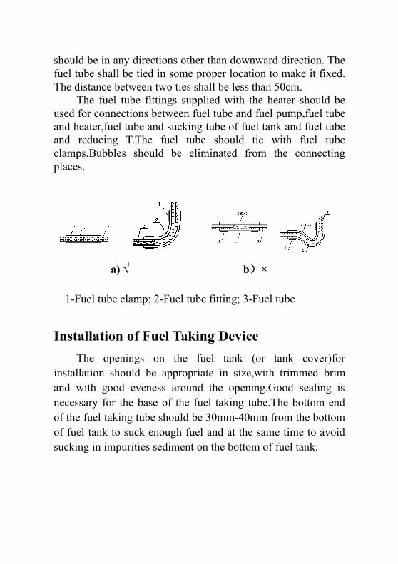
The fuel tube fittings supplied with the heater should beused for connections between fuel tube and fuel pump,fuel tubeand heater,fuel tube and sucking tube of fuel tank and fuel tubeand reducing T.The fuel tube should tie with fuel tubeclamps.Bubbles should be eliminated from the connectingplaces.
a) √ b)×
1-Fuel tube clamp; 2-Fuel tube fitting; 3-Fuel tube
Installation of Fuel Taking DeviceThe openings on the fuel tank (or tank cover)for
installation should be appropriate in size,with trimmed brimand with good eveness around the opening.Good sealing isnecessary for the base of the fuel taking tube.The bottom endof the fuel taking tube should be 30mm-40mm from the bottomof fuel tank to suck enough fuel and at the same time to avoidsucking in impurities sediment on the bottom of fuel tank.
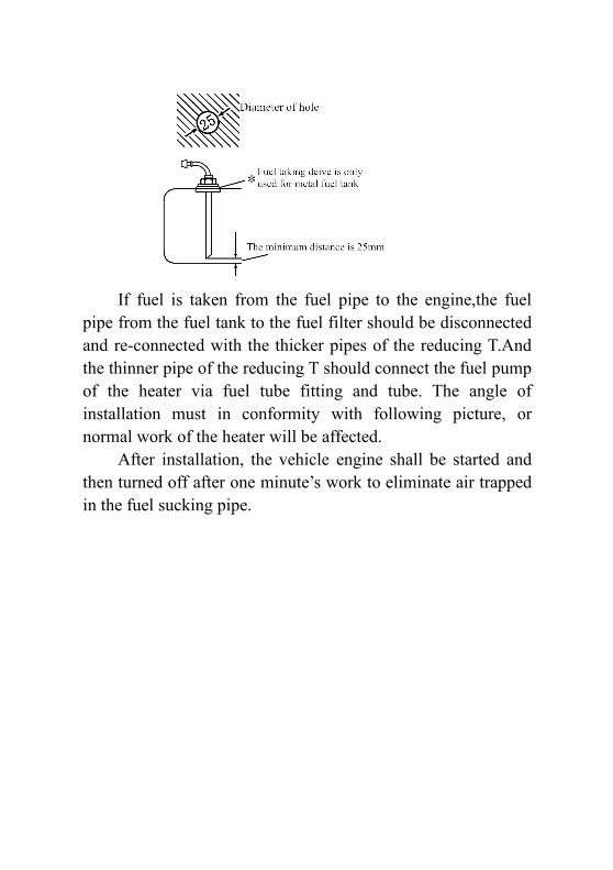
If fuel is taken from the fuel pipe to the engine,the fuelpipe from the fuel tank to the fuel filter should be disconnectedand re-connected with the thicker pipes of the reducing T.Andthe thinner pipe of the reducing T should connect the fuel pumpof the heater via fuel tube fitting and tube. The angle ofinstallation must in conformity with following picture, ornormal work of the heater will be affected.
After installation, the vehicle engine shall be started andthen turned off after one minute’s work to eliminate air trappedin the fuel sucking pipe.
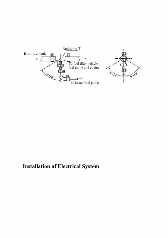
Installation of Electrical System
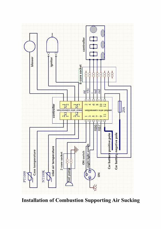
Installation of Combustion Supporting Air Sucking
Tube and Exhaust Discharge Tube
The combustion supporting air must be sucked in fromexternal fresh air outside the vehicle.The exhaust fromcombustion must be discharged into the air through exhausttube. Measures must be taken to avoid the exhaust fromre-entering he vehicle.
The tubes go through the outer wall or holes on thebottom of vehicle.Measures must be taken to prevent enteringof splash water. The tubes must be protected and can resistshock permanently.
Only the air inlet tube and exhaust tube provided with theheater can be used. The air inlet tube is a corrugated pipe madeof a aluminum tube that it’s surface is covered by plastic andpaper: The exhaust tube is corrugated stainless steel tube.Please identify them and do not make mistake st installation.To connect them with heater, please use the supplied clamps tofix them tightly on the combustion supporting air inlet andexhaust tube vent respectively. The protective hood on thevents of the air inlet tube and exhaust tube must be kept ingood condition. Do not damage them or remove them.
Both the air inlet tube the exhaust tube should comeoutwards and downwards from the heater, otherwise a Ø4mmhole shall be prepared at the bottom of the tube for discharge ofcondensation water. If the tube need curve, the radius cannot besmaller than 50mm.Also, the sum of all curve angles for each
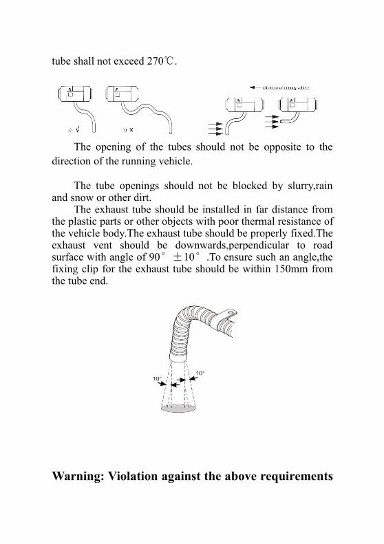
tube shall not exceed 270℃.
The opening of the tubes should not be opposite to thedirection of the running vehicle.
The tube openings should not be blocked by slurry,rainand snow or other dirt.
The exhaust tube should be installed in far distance fromthe plastic parts or other objects with poor thermal resistance ofthe vehicle body.The exhaust tube should be properly fixed.Theexhaust vent should be downwards,perpendicular to roadsurface with angle of 90°±10°.To ensure such an angle,thefixing clip for the exhaust tube should be within 150mm fromthe tube end.
Warning: Violation against the above requirements
may cause fire.
If the section of the exhaust tube inside the vehicle may betouched by passenger,a protective cover has to be installed toprevent human contact and scald.
Operation and ControlAfter the installation, the heater shall be turned on
repeatedly for a few times to make the fuel tube full-filled, soas to avoid staring failure due to lacking fuel.
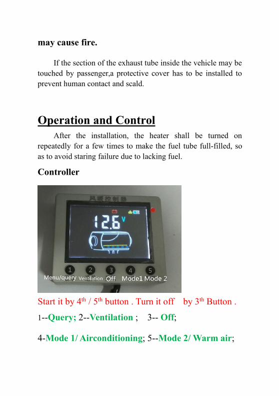
Controller
Start it by 4th / 5th button . Turn it off by 3th Button .
1--Query; 2--Ventilation ; 3-- Off;
4-Mode 1/ Airconditioning; 5--Mode 2/ Warm air;
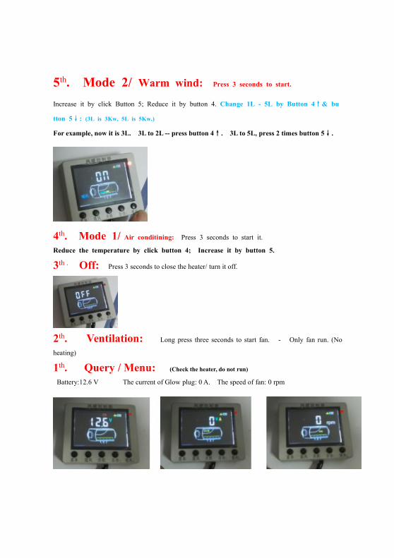
5th. Mode 2/ Warm wind: Press 3 seconds to start.
Increase it by click Button 5; Reduce it by button 4. Change 1L - 5L by Button 4↑& bu
tton 5↓: (3L is 3Kw, 5L is 5Kw.)
For example, now it is 3L. 3L to 2L -- press button 4↑. 3L to 5L, press 2 times button 5↓.
4th. Mode 1/ Air conditining: Press 3 seconds to start it.
Reduce the temperature by click button 4; Increase it by button 5.
3th . Off: Press 3 seconds to close the heater/ turn it off.
2th. Ventilation: Long press three seconds to start fan. - Only fan run. (No
heating)
1th. Query / Menu: (Check the heater, do not run)
Battery:12.6 V The current of Glow plug: 0 A. The speed of fan: 0 rpm

MaintenanceDuring the running of heater, it tests and checks the operatingstate and fault in the whole course, and the controller showsfault codes on the LCD / LED constantly.
The fault code of LCD screen:E01 ~ Power supply voltage is too low or too high. (10. 5V - 14V)
E02 ~ Oil pump open or short circuit.
E03 ~ Housing/ over-heating temperature sensor is open or shorted. (It is on the aluminum shell.)
E04 ~ Inlet sensor is open or shorted.
EO5 ~ Ignition/ Glow plug open or short circuit.
E06 ~ High temperature alarm of Inlet sensor
E08 ~ The Hall sensor of Fan is open or shorted
E09 ~ flame off failure.
E10 ~ Ignition failure.
E11 ~ The high temperature alarm of shell
E18 ~ LCD screen is disconnected to heater body
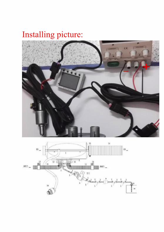
Installing picture: