Embed Size (px)
Citation preview

Air hydrAulic pumpmodel 95945
Assembly And OperAtiOn instructiOns
Due to continuing improvements, actual product may differ slightly from the product described herein.
®
3491 Mission Oaks Blvd., Camarillo, CA 93011
Visit our website at: http://www.harborfreight.com
tO preVent seriOus injury, reAd And understAnd All wArnings And instructiOns befOre use.
Copyright© 2007 by Harbor Freight Tools®. All rights reserved. No portion of this manual or any artwork contained herein may be reproduced in any shape or form without the express written consent of Harbor Freight Tools.
for technical questions or replacement parts, please call 1-800-444-3353.

Page 2SKU 95945 for technical questions, please call 1-800-444-3353.
specificAtiOns
Overall Pump Dimensions16-3/4” L (23” L including Air Cylinder) X 9-1/4” W (Including mounting base), 15-1/4” L (base)
Hydraulic Fluid Capacity 1.4 Quarts
Oil Capacity 44 Fluid oz.
Air Inlet Assembly1/4” -18 NPT FemaleDie-cast Air Valve with Locking Lever
Air Hose 3/8” I.D. X 4’
Air Pressure 110 to 120 PSI
Maximum Hydraulic Pressure 10,000 PSI
Operating Position Horizontal only
Features
Foot Pedal pump and releaseAir Bleeder Valve (Finger operated)Pedal Hold-Down LatchBolt-Down Holes in feet of Bracket
Weight 29 lb. (with Oil)
save this manual
You will need this manual for the safety warnings and precautions, assembly, oper-ating, inspection, maintenance and cleaning procedures, parts list and assembly diagram. Keep your invoice with this manual. Write the invoice number on the inside of the front cover. Write the product’s serial number in the back of the manual near the assembly diagram, or write month and year of purchase if product has no serial number. Keep this manual and invoice in a safe and dry place for future reference.
generAl sAfety rules
wArning!
reAd And understAnd All instructiOnsfailure to follow all instructions listed below may result in
serious injury.sAVe these instructiOns
wOrk AreA
keep your work area clean and well lit. Cluttered benches and dark areas invite accidents.
keep bystanders, children, and visitors away while operating this Air hydraulic pump. Distractions can cause you to lose control.
1.
2.
reV 07f

Page 3SKU 95945 for technical questions, please call 1-800-444-3353.
persOnAl sAfety
stay alert. watch what you are doing, and use common sense when operat-ing. do not use this Air hydraulic pump while tired or under the influence of drugs, alcohol, or medication. A moment of inattention while operating may result in serious personal injury.
dress properly. do not wear loose clothing or jewelry. contain long hair. keep your hair, clothing, and gloves away from moving parts.
do not overreach. keep proper footing and balance at all times. Proper footing and balance enables better control of the tool in unexpected situations.
use safety equipment. Always wear eye protection. Always wear ANSI-ap-proved safety goggles when using or performing maintenance on this tool. Dust mask, nonskid safety shoes, hard hat, or hearing protection must be used for ap-propriate conditions.
tOOl use And cAre
do not force the tool. use the correct tool for your application. The correct tool will do the job better and safer at the rate for which it is designed. Do not force the tool and do not use the tool for a purpose for which it is not intended.
tools are dangerous in the hands of untrained users. Keep children away from this Air Hydraulic Pump. Disconnect any air supply before leaving this Pump unat-tended.
maintain tools with care. keep tools clean. Properly maintained tools are less likely to bind and are easier to control. Do not use a damaged tool. Tag damaged tools “Do not use” until repaired.
check for misalignment or binding of moving parts, breakage of parts, and any other condition that may affect the tool’s operation. if damaged, have the tool serviced before using. Many accidents are caused by poorly maintained tools.
use only accessories that are recommended by the manufacturer for your model. Accessories that may be suitable for one tool may become hazardous when used on another tool.
serVice
tool service must be performed only by qualified repair personnel. Service or maintenance performed by unqualified personnel could result in a risk of injury.
when servicing a tool, use only identical replacement parts. follow instruc-tions in the “Inspection, Maintenance, And Cleaning” section of this manual. Use of unauthorized parts or failure to follow maintenance instructions may create a risk damage to the tool, and/or personal injury.
1.
2.
3.
4.
1.
2.
3.
4.
5.
1.
2.

Page 4SKU 95945 for technical questions, please call 1-800-444-3353.
specific sAfety rulesdo not adjust the factory set safety Valve. This valve should only be set, or reset by a qualified technician.
this air hydraulic pump must be secured tightly to a secure and stable sur-face to prevent dynamic pressure from moving it around as you work. Make sure it is not a tripping hazard.
follow all manufacturer’s instructions for the air compressor and all attach-ments you are using.
maintain a safe working environment. Make sure there is adequate surrounding workspace. Do not use this product in a damp or wet location.
the brass components of this product contain lead, a chemical known to the state of california to cause birth defects (or other reproductive harm). (Cali-fornia Health & Safety Code § 25249.5, et seq.)
neVer press the end of the hose against your skin or the skin of another person or animal. It is possible to inject fluids into your skin using this tool inap-propriately.
hydraulic components must be opened and serviced only by a qualified technician.
use clean, dry, and regulated compressed air. Do not exceed the recommended 110-120 PSI. Never use oxygen, carbon dioxide, combustible gases, or any other bottled gas as a power source for this tool.
maintain labels and nameplates on the tool. These carry important information. If unreadable or missing, contact Harbor Freight Tools for a replacement.
unpAckingWhen unpacking, check to make sure that the item is intact and undamaged. If any
parts are missing or broken, please call Harbor Freight Tools at the number shown on the cover of this manual as soon as possible.
1.
2.
3.
4.
5.
6.
7.
8.
9.

Page 5SKU 95945 for technical questions, please call 1-800-444-3353.
Assembly instructiOnsnote: For additional information regarding the parts listed in the following pages, refer to
the Assembly Diagram near the end of this manual.
wArning! Make sure the Air Hydraulic Pump is unplugged from its air supply and all pressure is released before making any adjustments to the tool.
note: The Pump comes fully assembled, but you will need to attach a hydraulic hose (not included) to the Air Inlet (9) located on the Pump Body (43) before using this Air Hydraulic Pump. This hydraulic hose (not included) is how you will attach all tools.
set up diAgrAm
recommended Air line components
hydraulic pump
Air compressor
note: For best service you should incorporate an oiler, regulator and in-line filter as shown in figure 1. If you are not using an automatic oiler system, before operation add a few drops of Pneumatic Tool Oil (not included) to the airline connection. Add an additional few drops after each hour of continual use. Hoses, couplers, oilers, regu-lators and filters are all available at Harbor Freight Tools.
OperAtiOn instructiOnsnote: This Air Hydraulic Pump is designed to operate either pneumatically or manually. It
is an ideal power source for various body, frame and alignment applications. It can be used with different ram kits, shop presses and hydraulic pullers (not included) that operate up to 10,000 PSI. It is equipped with a factory set Safety Valve to prevent sudden hydraulic failure. This Pump should be installed in a fixed location.
note: Check the oil level before using. The Pump Reservoir (46) should be full but after shipping it may need to be topped off. Check the oil in the pump reservoir prior to use. Remove the Filler Plug (36) and add the fluid being careful not to spill. Replace the Filler Plug (36) and wipe up any spilled hydraulic fluid. Periodically check the fluid level.
fOr best OperAtiOn: Before use, pull the Breather Valve (35) out. After use, replace the Breather Valve (35).
reV 07f
Page 6SKU 95945 for technical questions, please call 1-800-444-3353.
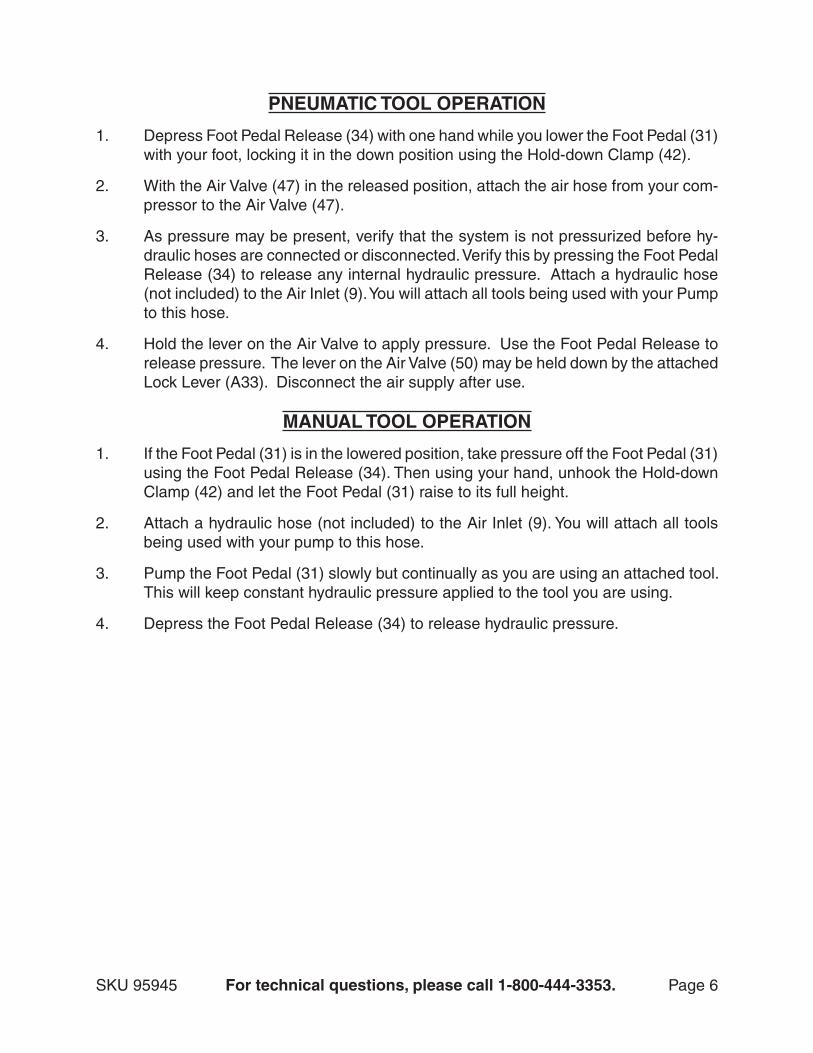
pneumAtic tOOl OperAtiOn
Depress Foot Pedal Release (34) with one hand while you lower the Foot Pedal (31) with your foot, locking it in the down position using the Hold-down Clamp (42).
With the Air Valve (47) in the released position, attach the air hose from your com-pressor to the Air Valve (47).
As pressure may be present, verify that the system is not pressurized before hy-draulic hoses are connected or disconnected. Verify this by pressing the Foot Pedal Release (34) to release any internal hydraulic pressure. Attach a hydraulic hose (not included) to the Air Inlet (9). You will attach all tools being used with your Pump to this hose.
Hold the lever on the Air Valve to apply pressure. Use the Foot Pedal Release to release pressure. The lever on the Air Valve (50) may be held down by the attached Lock Lever (A33). Disconnect the air supply after use.
mAnuAl tOOl OperAtiOn
If the Foot Pedal (31) is in the lowered position, take pressure off the Foot Pedal (31) using the Foot Pedal Release (34). Then using your hand, unhook the Hold-down Clamp (42) and let the Foot Pedal (31) raise to its full height.
Attach a hydraulic hose (not included) to the Air Inlet (9). You will attach all tools being used with your pump to this hose.
Pump the Foot Pedal (31) slowly but continually as you are using an attached tool. This will keep constant hydraulic pressure applied to the tool you are using.
Depress the Foot Pedal Release (34) to release hydraulic pressure.
1.
2.
3.
4.
1.
2.
3.
4.

Page 7SKU 95945 for technical questions, please call 1-800-444-3353.
inspectiOn, mAintenAnce, And cleAningwArning! Make sure the Air Hydraulic Pump is disconnected from its air supply and all hydraulic pressure is released before performing any inspection, mainte-nance, or cleaning procedures.
befOre use, inspect the general condition of the air hydraulic pump. Check for loose screws, misalignment or binding of moving parts, cracked or broken parts, cracked welds, cracked or broken hoses, leaking oil, and any other condition that may affect its safe operation. If abnormal noise or vibration occurs, have the problem corrected before further use. do not use damaged equipment.
After use, wipe off with a clean moist cloth. Be sure to wipe away any spilled hydraulic fluid.
mOnthly, check and refill hydraulic fluid. (See note page 6.)
trOubleshOOting
problem possible causes probable solutionsFoot Pedal (31) will not depress when trying to pump.
Pump Body (43) is too full of hydraulic oil.
Make sure the Breather Valve (35) is open, letting the trapped oil escape if necessary.
Low hydraulic pressure
Loose air fittings.
Cracked hose.
1.
2.
Tighten all fittings.
Change any cracked or broken hoses. dO nOt feel fOr leAks with hAnds. high pressure cAn inject fluid under skin. dO nOt repAir with tApe Or metAl clAmps. AlwAys replAce the hOse.
1.
2.
1.
2.
3.

Page 8SKU 95945 for technical questions, please call 1-800-444-3353.
pleAse reAd the fOllOwing cArefully
THe MANUFACTUReR AND/OR DISTRIBUTOR HAS PROVIDeD THe PARTS LIST AND ASSeM-BLY DIAgRAM IN THIS MANUAL AS A ReFeReNCe TOOL ONLY. NeITHeR THe MANUFACTUReR OR DISTRIBUTOR MAKeS ANY RePReSeNTATION OR WARRANTY OF ANY KIND TO THe BUYeR THAT He OR SHe IS QUALIFIeD TO MAKe ANY RePAIRS TO THe PRODUCT, OR THAT He OR SHe IS QUALIFIeD TO RePLACe ANY PARTS OF THe PRODUCT. IN FACT, THe MANUFACTUReR AND/OR DISTRIBUTOR eXPReSSLY STATeS THAT ALL RePAIRS AND PARTS RePLACeMeNTS SHOULD Be UNDeRTAKeN BY CeRTIFIeD AND LICeNSeD TeCHNICIANS, AND NOT BY THe BUYeR. THe BUYeR ASSUMeS ALL RISK AND LIABILITY ARISINg OUT OF HIS OR HeR RePAIRS TO THe ORIgINAL PRODUCT OR RePLACeMeNT PARTS THeReTO, OR ARISINg OUT OF HIS OR HeR INSTALLATION OF RePLACeMeNT PARTS THeReTO.
record product’s serial number here: note: If product has no serial number, record month and year of purchase instead.
note: Some parts are listed and shown for illustration purposes only, and are not available individually as replacement parts.
limited 1 yeAr wArrAntyHarbor Freight Tools Co. makes every effort to assure that its products meet high quality and durabil-
ity standards, and warrants to the original purchaser that this product is free from defects in materials and workmanship for the period of one year from the date of purchase (90 days if used by a professional contractor or if used as rental equipment). This warranty does not apply to damage due directly or indirectly, to misuse, abuse, negligence or accidents, repairs or alterations outside our facilities, normal wear and tear, or to lack of maintenance. We shall in no event be liable for death, injuries to persons or property, or for incidental, contingent, special or consequential damages arising from the use of our product. Some states do not allow the exclusion or limitation of incidental or consequential damages, so the above limitation of exclusion may not apply to you. THIS WARRANTY IS eXPReSSLY IN LIeU OF ALL OTHeR WARRANTIeS, eXPReSS OR IMPLIeD, INCLUDINg THe WARRANTIeS OF MeRCHANTABILITY AND FITNeSS.
To take advantage of this warranty, the product or part must be returned to us with transportation charges prepaid. Proof of purchase date and an explanation of the complaint must accompany the merchan-dise. If our inspection verifies the defect, we will either repair or replace the product at our election or we may elect to refund the purchase price if we cannot readily and quickly provide you with a replacement. We will return repaired products at our expense, but if we determine there is no defect, or that the defect resulted from causes not within the scope of our warranty, then you must bear the cost of returning the product.
This warranty gives you specific legal rights and you may also have other rights which vary from state to state.
3491 Mission Oaks Blvd. • PO Box 6009 • Camarillo, CA 93011 • (800) 444-3353

Page 9SKU 95945 for technical questions, please call 1-800-444-3353.
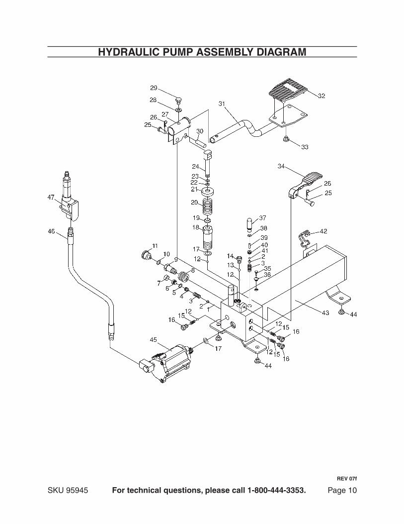
hydrAulic pump pArts list
part description Q’ty1 Ball 1
2 Ball cap 2
3 Spring 2
4 Screw 1
5 O-ring 1
6 Safety Valve 1
7 Plastic Cap 1
8 Coupling Ring 1
9 Air Inlet 1
10 O-ring 1
11 Dust Cap 1
12 Ball 4
13 Ball 1
14 Screw 1
15 Spring 3
16 Screw 3
17 Washer 2
18 Screw 1
19 Dust Ring 1
20 Spring 1
21 Spring Cap 1
22 O-ring 1
23 Nylon ring 1
24 Piston 1
part description Q’ty25 Pin 2
26 R-pin 2
27 Handle Socket 1
28 Washer 1
29 Bolt M8x25 1
30 Pin 1
31 Foot Pedal 1
32 Rubber Pad 1
33 Rubber 1
34 Rubber Foot Pedal 1
35 Breather Valve 1
36 Filler Plug 1
37 Oil Release piston 1
38 O-ring 1
39 Pin 1
40 Screw 1
41 Ball 1
42 Hold-down clamp 1
43 Pump Body 1
44 Rubber 4
45 Air Pump Assembly 1
46 Air Hose 1
47 Valve Body 1
note: In both the hydraulic pump parts list on this page, and the Air pump parts list on page 11, numbers 46 and A32 are for the same Air Hose, and numbers 47 and A43 are both for the same Valve Body.
reV 07f
Page 10SKU 95945 for technical questions, please call 1-800-444-3353.
hydrAulic pump Assembly diAgrAm
reV 07f

Page 11SKU 95945 for technical questions, please call 1-800-444-3353.
Air pump pArts list
part description Q’tyA01 Air Pump Cylinder 1
A02 Nut 1
A03 Sealing Ring 1
A04 Nylon Ring 1
A05 Copper Ring 1
A06 Air Cylinder Seat 1
A07 Nut 1
A08 Spring 1
A09 Air Pump Piston 1
A10 O-ring 2
A11 Big Piston 1
A12 Air Cylinder 1
A13 Screw 2
A14 Lock Washer 2
A15 Safety Cover 1
A16 Filter 1
A17 Silencing Pad 1
A18 Small Piston 1
A19 O-ring 1
A20 O-ring 1
A21 Sealing Ring 1
A22 Bolt 3
A23 Nylon Ring 1
A24 O-ring 2
part description Q’tyA25 O-ring 1
A-26 Air Cylinder Cap 1
A27 Bolt 4
A28 Coupler Seat 1
A29 Retaining Ring 1
A30 O-ring 2
A31 Coupler 1
A32 Air Hose 1
A33 Lock Lever 1
A34 Release Lever 1
A35 Nut 1
A36 O-ring 1
A37 O-ring 1
A38 Packing 1
A39 Throttle 1
A40 Spring 1
A41 Lock Nut 1
A42 Bolt 1
A43 Valve Body 1
A44 Screw 1
A45 Screen 1
A46 O-ring 1
A47 Quick Coupler-male 1
A48 Coupler Seat 1

Page 12SKU 95945 for technical questions, please call 1-800-444-3353.
Air pump Assembly diAgrAm