Embed Size (px)
Citation preview

8/7/2019 Air Inlet and Exhaust System
http://slidepdf.com/reader/full/air-inlet-and-exhaust-system 1/5
8/7/2019 Air Inlet and Exhaust System
http://slidepdf.com/reader/full/air-inlet-and-exhaust-system 2/5
Basic Operation
The following components make up the air inlet and exhaust system:
Turbocharger
Cylinder head
Valves and valve train components
Piston and cylinder
Exhaust manifold
These engines are equipped with a turbocharger. Turbocharged engines are more responsive andturbocharged engines have increased horsepower.
Turbocharger
Air inlet and exhaust system
(1) Exhaust manifold
(2) Exhaust valve
(3) Inlet valve
(4) Air inlet
(5) Exhaust outlet
(6) Compressor side of the turbocharger
(7) Turbine side of the turbocharger
Page 2 of 5966H Wheel Loader A6G00001-UP (MACHINE) POWERED BY C11 Engine(SEBP384...
1/15/2010https://sis.cat.com/sisweb/sisweb/techdoc/techdoc_print_page.jsp?returnurl=/sisweb/siswe ...

8/7/2019 Air Inlet and Exhaust System
http://slidepdf.com/reader/full/air-inlet-and-exhaust-system 3/5
The turbocharger works in order to produce boost across the entire engine RPM range. The increased
Illustration 2 g01323377
(8) Compressor housing
(9) Oil inlet port
(10) Bearing
(11) Turbine housing
(12) Turbine wheel
(13) Air inlet
(14) Exhaust outlet
(15) Compressor wheel
(16) Bearing
(17) Oil outlet port
(18) Exhaust inlet
Page 3 of 5966H Wheel Loader A6G00001-UP (MACHINE) POWERED BY C11 Engine(SEBP384...
1/15/2010https://sis.cat.com/sisweb/sisweb/techdoc/techdoc_print_page.jsp?returnurl=/sisweb/siswe ...

8/7/2019 Air Inlet and Exhaust System
http://slidepdf.com/reader/full/air-inlet-and-exhaust-system 4/5
boost at low RPM fills the combustion chamber with dense air. The dense air mixes with the fuel inorder to promote a complete combustion.
The turbocharger has a compressor wheel (15) and a turbine wheel (12). The compressor wheel and theturbine wheel are connected to a common shaft. The shaft is supported by bearing (10) and bearing (16).The bearings are lubricated by pressurized engine oil. The oil enters through oil inlet port (9). Theengine oil lubricates the bearings and the oil removes heat. The oil returns to the oil pan through oil
outlet port (17) .
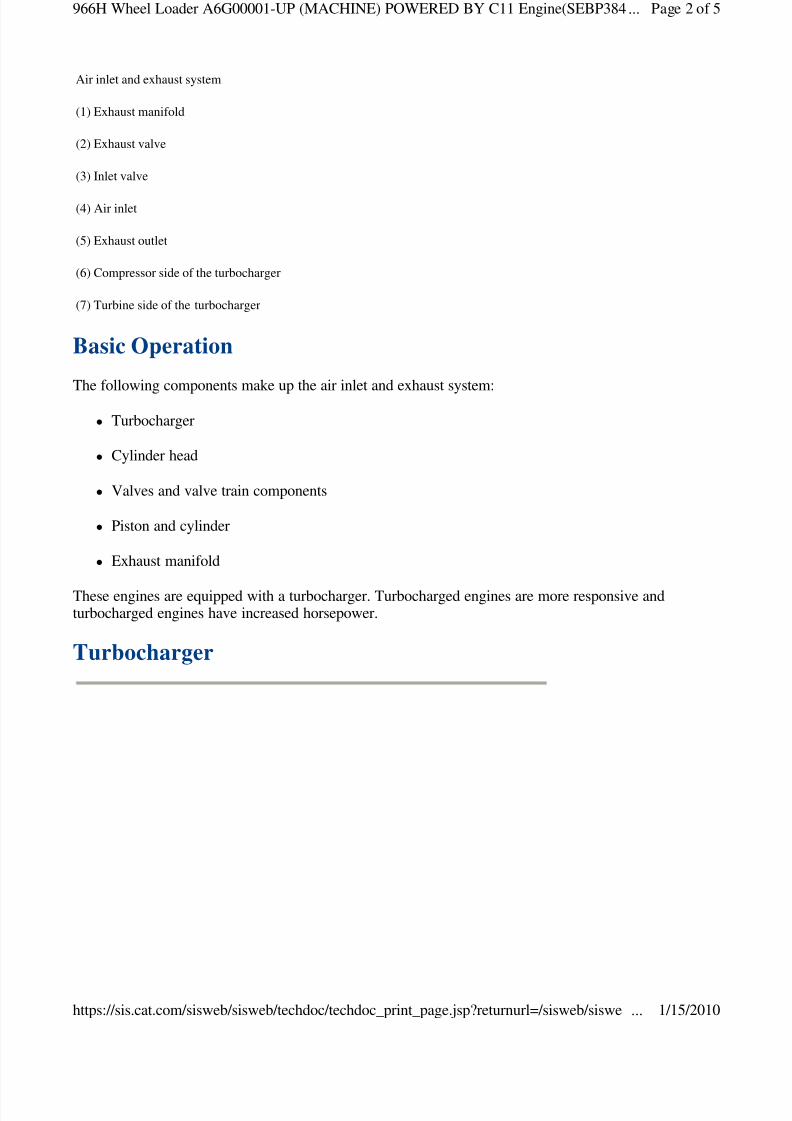
Valve System Components
Illustration 3 g01323378
Page 4 of 5966H Wheel Loader A6G00001-UP (MACHINE) POWERED BY C11 Engine(SEBP384...
1/15/2010https://sis.cat.com/sisweb/sisweb/techdoc/techdoc_print_page.jsp?returnurl=/sisweb/siswe ...
8/7/2019 Air Inlet and Exhaust System
http://slidepdf.com/reader/full/air-inlet-and-exhaust-system 5/5
The valve system components control the flow of inlet air into the cylinders and out of the cylindersduring engine operation. The valve mechanism also operates the fuel injector.
The camshaft must be timed to the crankshaft in order to get the correct relation between the pistonmovement and the valve movement.
The camshaft has three camshaft lobes for each cylinder. The lobes operate the inlet valves, exhaustvalves and unit injectors. As the camshaft turns, lobes on the camshaft cause lifters (24) to movepushrods (21) up and down. Upward movement of the pushrods against rocker arms (19) results indownward movement (opening) of valves (23) .
Each cylinder has two inlet valves and two exhaust valves. The valves are actuated at the same time by avalve bridge (20). Valve springs (22) close the valves when the lifters move down.
(19) Rocker arm
(20) Valve bridge
(21) Pushrod
(22) Valve spring
(23) Valve
(24) Lifter
Copyright 1993 - 2010 Caterpillar Inc.All Rights Reserved.Private Network For SIS Licensees.
Fri Jan 15 15:32:06 UTC+0200 2010
Page 5 of 5966H Wheel Loader A6G00001-UP (MACHINE) POWERED BY C11 Engine(SEBP384...
1/15/2010h // i / i b/ i b/ hd / hd i j ? l / i b/ i


![Frame 6B pre-owned Equipment listControl system [--] Speedtronic MarkV (was MarkIV, upgraded in 2000) Design temperature inlet air exhaust air [°C] [°C] 15 540 ÷ 550 after installation](https://img.pdfslide.net/doc/110x75/5e7f52230696e422ad7b2751/frame-6b-pre-owned-equipment-list-control-system-speedtronic-markv-was-markiv.jpg)