Embed Size (px)
Citation preview

AIRLEAKAGE CONTROL
GUIDELINES FOR INSTALLATION OF AIR LEAKAGE CONTROL
MEASURES IN COMMERCIAL BUILDINGS
A&E Services Brsnch
Technology Sector
RD&D Division

PREFACE
This project on Air Leakage Control Retrofit Measures for Higb-Rise Office Buildings was proposed by Technology, Research, Development and Demonstration and funded by the Real Property Program. 1 managed the project and the report was prepared by Canam Building Envelope Specialists Inc. with assistance from Carson Woods Architects Limited and EMS Marketing Communications Inc.
Every year, Public Works and Govemment Services Canada (PWGSC) spends vast sums ofmoney on the repair and retrofit of buildings. Improved technica1 knowledge and better understanding of building envelopes, particularly on air leakage and thermal characteristics are extremely important. Cost-effective air-sea1ing measures in the management of existing buildings and renovation of old buildings will help in achieving maximum energy efficiency by reducing energy consumption and maintenance costs, improving indoor environment and utilizing energy resources in an environmentally responsible and cost-effective fashion. The implementation of the air leakage control retrofit measures outlined in this report could result in very significant savings.
The air-Ieakage control guidelines developed form this project will become a most frequently used tool in the construction industry.
MoeCheung
Public Works and Government Services Canada Architectural and Engineering Services Technology Division, RD&D Sir Charles Tupper Building, Room D525 Ottawa, Ontario KIAOM2 Telephone: Fax:
(613)736-2121 (613)736-2826

AÇKNOWLEDGEMENT
This project was partially fundee! under Ihe Prollram on Enel'llY Research aad Developmenl (pERD). Enel'llY Emcienty • Buildings Task 1.4.
DISCLAJMER
Tbis report is distrihuted for informatlona. purposes only and does DOl DetessarUy renetl the vlews of the Covemment of Canada nor tonstltute an eDdorsement of current or future statu. of aDy polity or prollram. Neilher Canada or lu minislers, omcers, employees or allents makes any warraDty ln respect of tbis report or assumes any lIability arilinl out of tbis report.
TABLE OF CONTENTS
1. Section 1 Introduction and General Principles 1-8
2- Section 2 Air Leakage by Building Component 1-2
3. Section 3 Materials and Methods 1-47
4. Section 4 Design Process and Contracting Procedures 1-3
5. Section 5 Conclusions, References and Recommendations 1-2

PRACTICAL GUIDELINES FOR DESIGNERS, CONTRACTORS AND DEVELOPERS, ON THE INSTALLATION OF AIR LEAKAGE CONTROL MEASURES IN NEW AND EXISTING HIGH-R1SE COMMERCIAL BUILDINGS
Section 1: INTRODUCTION AND GENERAL PRINCIPLES
1.1 Scope and Use of pocument
1.1.1. This document should always be used in conjunction with the Air Barrier TEK-AlD, available from Construction Specifications Canada at 100 Lombard Street, Suite 200, Toronto M5C 1M3. Tel: (416) 777-2198. Fax: (416) 777-2197. Several very important reference works are listed, together with sources in the TEK-AID itself.
In addition, valuable information is contained in the following:
CMHC: Protocol for measuring air leakage and air flow patterns in high-rise apartment buildings. Report No. CR 5855.1 April 18, 1990.
CMHC: Summary Report: Air Permeance of Building Materials. June 17, 1988.
CMHC: Structural Requirements for Air Barriers. Report No. 30133.0R1. August 13, 1991.
CMHC: Testing of Air Barriers Construction Details. Report No. 30132.0R/2. August 26,1991.
Public Works Canada: Cladding Study (pending publication). Phases 1 to 4. Reports 1990.
Public Works Canada: Durability Study (pen ding publication). Phases 1 and 2. Reports 1991/92.
1.1.2 Covers all new and existing buildings of more than three stories intended for commercial use.
1.1.3 The purpose of this document is to reduce the negative economic, environmental and human impacts of inadequate, improperly designed, improperly installed and improperly maintained air barrier systems. Too many examples exist in Canada's high-rise commercial building stock. Practical techniques exist which can be used to virtually eliminate poor air barriers. The authors of this document have chosen to focus on areas which will provide the fastest and most notiœable benefits.
1-1
Inadequate air barrier systems allow leakage of air through holes, leaks, cracks and gaps. The leaking air carries humidity as weIl as assorted partic1es of dust, dirt and other contaminants. These unfriendly elements are deposited in building materials through which the air passes on its way into, out of, or through the structure. For Ieakage to occur, there has to be an imbalance of air pressure from one side to the other side of the air barrier. Such imbalances are easy to find in high-rise buildings. Sometimes they are caused by wind pressure on the exterior; sometimes by stack effect, as warm air travels quickly upwards through the building; sometimes by exhaust systems getting rid of stale air; and sometimes by the mechanical system operator trying (against the odcls) to condition the indoor environment for maximum corn fort.
Faulty air barrier systems affect buildings and occupants in several ways. The most frequent and noticeable inc1ude: uncomfortable indoor environments; unnecessarily high heating and air conditioning costs; accelerated decay of building materiaIs, particularly in walls, dadding systems, windows and roofing; and deteriorating aesthetic appearance of the outside of the building. Ali of these problems can in sorne part be attributed to faulty air barrier system design and/or installation.
In most instances, geographical location and indoor environmental requirements are not the major causes of air leakage. In the experience of the authors, the worst areas of leakage are: Mechanical Penthouses; Soffits; Parapets; Punched Windows; Overhang Parapets; Links Connecting Below Grade Areas to Other Buildings; Joints Between One System and Another; Doors.
What is a good air barrier system?
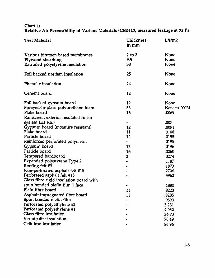
It should be continuously impermeable to air. According to the National Research Council of Canada, suggested maximum permeability for each dass of air barrier is as follows:
Class 1 (Relative Humidity less than 27%): 0.15 L/s/m2; Class 2 (Relative Humidity 27-55%): 0.10 L/s/m2; Class 2 (Relative Humidity greater than 55%): 0.05 L/s/m2. For relative air perrneability, see Chart 1: Relative Air Penneability of Various Materials
It should also be structurally supported 50 that it cannot shear; durable; and accessible for maintenance and repaîr. Where should it be located?
In theory, anywhere in the building envelope, providing it can achieve ail
1-2
of the above. Traditionally, this means placing it on the warm side of the insulation. It should be in form contact with the insulation. It may also be located on the cold side of an insulated assembly, but care should be taken to avoid the possibility of moisture problems inside the assembly if the air barrier system is also acting as a vapour barrier. In this location, the air barrier system should have a water vapour permeance greater than that of a Type 2 Vapour Barrier (57.5 metric perms). In ail cases, experts should be consulted for advice on the location of the air barrier system and the vapour diffusion retarder.
Compartmentalization and Decoupling
ln retrofit applications, where it is possible to create continuity of the air barrier, the interior corners of the building should be sealed in order to 'compartmentalize' each floor area. The effect will be to reduce the pressures caused by the flow of air around the building inside the wall system. It is also advisable to 'decouple' the building vertically in order to reduce the stack effect. This is achieved by a variety of measures, e.g., creating elevator lobbies on each fIoor, and controlling air leakage through fire doors and ail vertical penetrations. The National Building Code requires fIoor perimeters to be fire-stopped. They should also be sealed to crea te an air barrier, which will also prevent smoke transfer.
Good Iuck, and remember:
There are holes that are left and There are holes that are made 50 whoever can fill them Has an excellent trade!
1.2 The issues
1.2.1 Energy Conservation
1.2.1.2. Backsround
In a commercial building, the heating, ventilation and airconditioning (HVAC) system maintains the indoor environment. The HV AC system provides the required conditioned air to different locations based on specifie needs, and in a high-rise commercial building, it is also able to satisfy the ventilation requirements. ln most high-rise buildings, the
1-3
1.2.1.3.
______ L_ -~ L. __ L. _:_ •• __ .... ;1 ........ """'" ~I"t..oc:. "nt ,"",lv nn air l .... aka-~ ::iUpply UI IIC':tll cau VIli:ULJ,UU,&..."U -""_ ............ • _.J -_. --- ·ç------OIJ!;;
through the building envelope. Instead, the mechanical ventilation system is usually designed to counteract the flow of air leakage through the envelope by keeping a slightly
•• ..... 1).. 'A' .'-' 'H' posltlve ifiuOOï aiT pressure. ~ .. OVl_lng .. nlS pOS1 ... ve pressure results in the loss of some conditioned air through the envelope's air leakage paths. The leakage has two effects: (i) it increases the moisture loading on the envelope, and (ii) it increases operating costs because of the loss of conditioned (heated or cooled) air.
Potential Cost Benefits
It is difficult to gauge the effect of air leakage through building envelope in commercial buildings. Since there is very little information available in published literature. According to data published in the ASHRAE Handbook, air leakage in high-rise commercial building typically represents 15 to 30% of the buildings thermalload or roughly 4 to 8% of the total energy requirements. This is a significant component. Any reduction in such uncontrolled air leakage, without sacrifidng indoor air quality, will have the potential of redudng the overall peak heating and cooling demand and the energy costs. There are, however, a growing number of before-and-after studies of how energy consumption, demand and costs can be reduced by air leakage control measures in high-rise buildings. Some building scientists have reported theoretical savings in a very wide 20 to 60% range based on detailed energy input/output audits. These same sources have observed air leakage control retrofit measures achieving a documented saving of close to 40% for a V.s. six-storey office building.
A recent study published by PWC showed that for a 17-storey office building (Brooke-Claxton-19,730 m2 floor area), the whole building airtightness test results showed an improvement in airtightness of 37% after implementing window weatherstripping and caulking, and the sealing of vertical columns from the inside. The exterior metal panel of a 2D-storey, 12,800 m2 floor area, high-rise office building (Dunton Tower) was replaced with a curtain-wall c1adding system. This remodelling improved the airtightness by 43% and reduced the annual energy consumption by more than 11%.
1-4

A survey of four electrically-heated high-rise residential buildings1 in Ontario showed that the peak heating demand varies from 35 to 70 W /m2 of floor space. During the peak win ter conditions (below - 18 deg. C. ambient temperature and greater than 5 m/s or 18 km/hour wind velocity), the air infiltration component contributed to the heating load by 12 to 25 W 1m2 - roughly 25 to 40% of peak heating demand.
In 1991/92, Ontario Hydro sponsored a field study to evaluate the impact of air-sealing retroEit measures on energy and peak demand requirements of two high-rise (21-storey and a 10-storey) residential buildings. This study provided startling results that can be summarized as follows:
o air sealing of gross leaks of building envelope (windows, exterior doors, baseboards, shafts and other envelope and vertical penetrations) improved the airtightness by 30 to 40%;
o air leakage control offered a reduction in peak space heating demand by 4 to 7 W /m2 of floor spa ce, and the reduction of annual heating energy was 7.5 to 11.5 kWh/m2lyear;
o the indoor air quality tests performed and after the air sealing showed that there was no negative impact on the general conditions of comfort and air quality in both buildings;
o the simple payback period for air sealing retrofit was four to six years.
There are several tools available to assess the potential energy and costs benefits of air leakage control. One such assessment method is the air leakage control assessment procedure, ALCAP, developed by Ontario Hydro for high-rise residential buildings, and its success led to ALCAP's use on more than one hundred and eighty low and high-rise multi-unit residential buildings for Ontario Hydro's Non-Profit Housing Retrofit Program. ALCAP can be easily adapted for commercial buildings by using a more sophisticated model for
The high-rise building is defined as a building with three or more storeys
1-5
the assessment of mechanical systems.
1.2.2. Structural Intesrity and Building Lite Expectancy
As will be shown in Sections 2 and 3 of this document, wind pressure and stack effect have devastating effects on high-rise buildings with faulty air bamers. Wind on the outside of a building crea tes tremendous pressures on the structure. If there are holes available through which air can migra te, the pressure imbalances caused by wind and stack effect will help it do so. Stack effect causes air to rise through the building and exfiltrate from the higher lIoors in any way it cano As this happens, humidity, corrosives and contaminants present in the air do untold damage to everything they touch, from insulation and brickwork, through cladding and every kind of decorative faeing. As corrosion and decay progress, the integrity of the structure is weakened and its Iife expectancy is reduced.
1.2.3 Safety and Liability
From the building owner's point of view, the economic implications of decaying building materials are very serious. The Hfe of a costly building can be cut drastically, operating costs for energy increase, tenant complaints increase, maintenance costs increase, and perhaps most expensive of ail, the safety of people passing by the exterior of the building is threatened and the prospect of Iiability is present, when eventually exterior pieces of the building start to drop off. Injury and damage caused by smoke can also be reduced if vertical smoke transfer is prevented by properly decoupling a building (see 1.1.3. Where should it be located?)
1.2.4 Occupant Comfort and Health
Uncontrolled air leakage also causes problems for people working in a building. 5trong drafts caused by stack effect within the building can be unpleasant or even dangerous. A leaky building often features low humidity levels during winter months, which have been shown to affect comfort, morale, health and absenteeism. Research conducted in twelve public schools by Prof. D.H. Green, University of Saskatchewan, showed absenteeism reduced by 20% when relative humidity in the cJassrooms was raised from 20to 35%. A further study conducted by the staff of Theodore Sterling Ltd., Vancouver, set an optimum range of relative humidity in the workplace (40 to 60%). The study showed that airborne bacteria, viruses and fungi become more evident when RH remains below or above this range for extended periods of lime. (See Chart 2: Optimum relative humidity ranges for health). When humid, contaminated air fights its way out through the building exterior, a common result is fungus or mol d, with
1-6
their associated health hazards.
1.2.5 Aesthetics
One way to recognize a leaky building is by the 'Scars of poor air barrier design and installation'. Efflorescence, water staining, flaking bricks, rust streaks, large holes in masonry, and cracked and peeling finishes are the identification marks of many high-rises with air barrier problems.
1-7
Chut 1: Relative Air Permeability of Various Materials (CMHC), measured leakage at 75 Pa.
Test Malerial
Various bitumen based membranes Plywood sheathing Extruded polystyrene insulation
Foi! backed urethan insulation
Phenolic insulation
Cement board
Foi! backed gypsum board Sprayed-in-place polyurethane foam Flake board Rainscreen exterior insulated finish system (E.I.F.5.) Gypsum board (moisture resistant) Flake board Partic1e board Reinforced perforated polyolefin Gypsum board Partic1e board Tempered hardboard Expanded polystyrene Type 2 Roofing felt #3 Non-perforated asphalt felt #15 Perforated asphalt felt #15 Glass fibre rigid insulation board with spun-bonded olefin film 1 face Plain fibre board Asphalt impregnated fibre board Spun bonded olefin film Perforated polyethylene #2 Perforated polyethylene #1 Glass fibre insulation Vermiculite insulation Cellulose insulation
Thickness in mm
2 to 3 9.5 38
25
24
12
12 53 16
12 11 12
12 16 3
11 11
Lls/m2
None None None
None
None
None
None None to .00024 .0069
.007
.0091
.0108
.D155
.0195
.0196
.0260
.0274
.1187
.1873
.2706
.3962
.4880
.8223
.8285
.9593 3.231 4.032 36.73 70.49 86.96
1=5
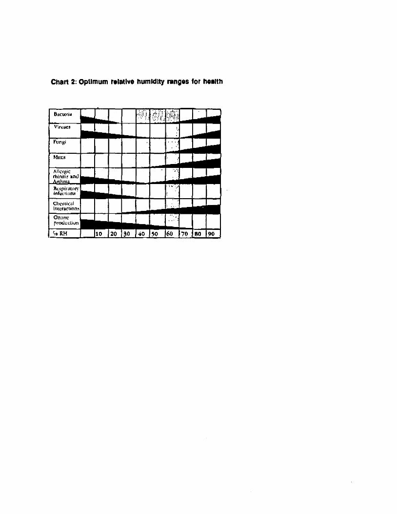
Chart 2: Optimum ralatlve humldlty ranges for h •• lIh
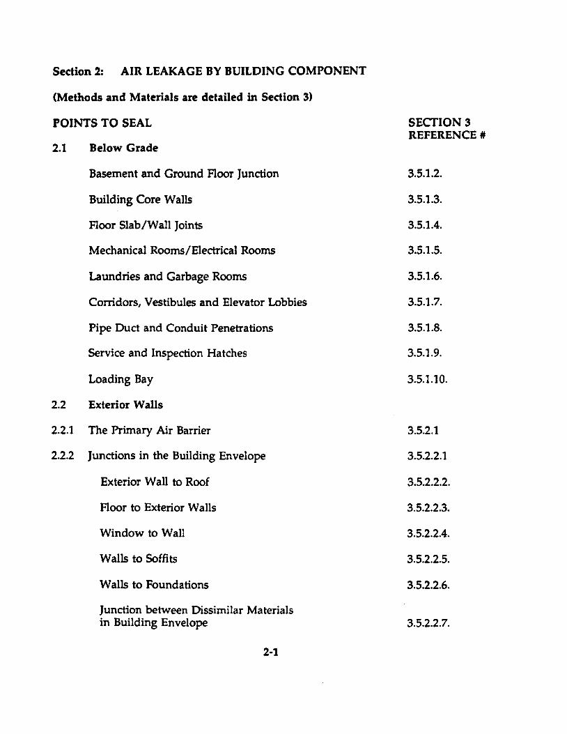
Section 2: AIR LEAKAGE BY BUILDING COMPONENT
(Methods and Materials are detailed in Section 3)
POINTS TO SEAL
2.1 Below Grade
Basement and Ground Floor Junction
Building Core Walls
Floor Slab/Wall Joints
Mechanical Rooms/Electrical Rooms
Laundries and Garbage Rooms
Corridors, Vestibules and Elevator Lobbies
Pipe Duet and Conduit Penetrations
Service and Inspection Hatehes
Loading Bay
2.2 Exterior Walls
2.2.1 The Primary Air Barrier
2.2.2 Junctions in the Building Envelope
Exterior Wall to Roof
Floor to Exterior Walls
Window to Wall
Walls to Soffits
Walls to Foundations
Junction between Oissimilar Materials in Building Envelope
2-1
SECTION 3 REFERENCE #
3.5.1.2.
3.5.1.3.
3.5.1.4.
3.5.1.5.
3.5.1.6.
3.5.1.7.
3.5.1.8.
3.5.1.9.
3.5.1.10.
3.5.2.1
3.5.2.2.1
3.5.2.2.2.
3.5.2.2.3.
3.5.2.2.4.
3.5.2.2.5.
3.5.2.2.6.
3.5.2.2.7.
Compartmentalization of Cavities in the Building Envelope 3.5.2.2.8.
2.3 Exterior Wall Openings
Extemal Doors 3.5.3.1
Revolving Entrance Doors 3.5.3.2
Pressurized Vestibule Entrances 3.5.3.3.
Operable Windows - Sash & Casement 3.5.3.4.
Non-operable Windows 3.5.3.5.
Electrical Penetrations in Exterior Walls 3.5.3.6.
Ventilation, Louvres and Grills 3.5.3.7.
Incrementai Through the Wall Units 3.5.3.8.
2.4 Interior Walls and Openings
Partitions to Exterior Walls Junctions 3.5.4.1.
Fire Rated Doors and Partitions 3.5.4.2.
Plumbing Holes, Electrical and Communication Conduit 3.5.4.3
Ductwork Penetrations 3.5.4.4.
2.5 Roofs and Roof Openings
Drains and Cold Vents 3.5.5.1.
Chimneys and Hot Vents 3.5.5.2.
Skylights, Curb Mounted Equipment 3.5.5.3. and Smoke and Access Hatches
Mechanical Penthouses 3.5.5.4.
2.7 Shafts 3.6.
2-2
Section 3 MATERIALS AND METHODS
Many materials have the characteristics required of air barriers while others qualify only in part. Sorne materials having acceptable air permeability ratings may not be suitable for air barrier construction for other reasons such as susceptibility to degradation, thermal instability, moisture sensitivity, chemical incompatibility, insufficient strength to take pressure loads or difficulty in making durable joints.
Unsupported polyethylene film cannot be recommended as an air barrier material for high-rise buildings because of susceptibility to damage by high wind loads and the difficulty of sealing joints effectively and durably. Some trowel-applied mortars or pargings tend to become brittle and cannot maintain a seal if the building moves or the substrate shrinks. These materials also cannot bridge gaps or cracks in the substrate and so must often be combined with some other air sealing technique.
Other materials have characteristics which may influence where they can be used. Bituminous membranes, asphalt impregnated gypsum board, foil backed gypsum board, foil backed rigid insulations and extruded polystyrene foam insulation have resistance to vapour diffusion, so they must be used with care in exterior situations where they May create secondary vapour barriers beyond the dew point. Relative air permeabilities of various materials measured at 75 Pa. are listed in (Chart 1 at the end of Section 1).
3.1. Iointins Materials and Membranes
The weakest points in Most air barrier systems are the joints - between materials and different components forrning the system, where services penetrate, and around operable openings such as doors and windows. Depending upon the design of the air barrier system, a variety of jointing materials are available. These can be c1assified under 4 headings: (1) Sealants: caulking materials, mastics, coatings, etc. (2) Weather-stripping: gaskets, packing, etc. (3) Foams: single and two-component polyurethane. (4) Membranes.
3.1.1. Sealants
Apart from the usual considerations relating to these products Le., durability, colour, ease of use, economics, paintability, etc., a primary concem, particularly, in retrofit, is odour. Most sealants contain solvents which will smell when freshly applied but which will fade fairly quickly. Some will not. Some c1ear materials will yellow with aging. For MOst air leakage control installations, to avoid colour matching problems, c1ear, rubber based paintable products which are stipulated by the manufacturer, as suitable for interior use, should be used. For some applications, e.g., large cracks, sealants must be used together with "backer rods".
3-1

De-coupling of floors in existing buildings built prior to 1985 may require the installation of appropriate sealants to supplement the existing mineralfibre, fire-stopping materials stuffed into vertical penetrations and around floor edges. Such sealants may have to he installed from undemeath where access is available above ceilings. Materiais such as speciai mortars are available which are self supporting and will meet appropriate fire-rating requirements when tested in accordance with CAN 4-S115-M "Standard Method of Fire Tests of Firestop Systems", ASTM-E814-83 "Standard Method of Fire Tests of Through-Penetration Fire Stops" and CAN 4-S1l4-M "Standard Method of Test for Determination of Non-Combustibility in Building Materials.
3.1.2. WeatherstriRPinS
Tightening windows, as a retrofit measure, is usually cost-effective. Weather-stripping systems are available for all types of windows. A whole variety of plastic extrusions, replacement pile, in-situ gasket forming and closed-cell rubber and plastic foam products can he used, in combination, to upgrade existing windows. Durability is a primary consideration with steel and commercial doors. Experience has shown that heavy-duty moulded Vseal type products installed on the jamb, or vinyl-clad foam compressiontype materials mounted on the stop, will last longer and stay tight even when doors warp. Door bottom seals should he installed on front and rear faces of doors and checked every year. Refer to Section 3.5.3. "Exterior Wall Openings".
3.1.3. In-situ Foams
These fall generally into two groups: two component and one component. Urethanes are the most common type of foam and, as two-component types, come in a vast range of formulations - created with a variety of densities, rates of cure, permeability, and levels of fire and smoke resistance to suit a wide range of applications. For air barrier use, densities of 16 to 50 kg/m3 (1.0 to 31b/ft3) range are typical where the lower density is used to reduce cost, although the greater open cell characteristics of such foam will reduce its bonding and structural strengths. Curing is by chemical means, Product and Installation Standards have been established, plus Environmental concerns dealt with to the satisfaction of the Canadian Construction Materials Board (C.C.M.B.).
Two component foams can he used as insulating air/vapour barriers, spray applied, and as sealants where larger gaps and holes have to he filled, such as roof/wall intersections, window perimeters and mullions, and hard-toaccess areas. They are generally applied using specialized truck-mounted
3-2
equipment in large scale projects, however, for smaller and more difficult areas, self-contained, portable and disposable kits are available in different sizes.
One component foams are ail formulated as slow-reacting urethanes and are cured by moisture in the air. A variety of brands are available with basically the same chemical structure and density but variable rates of postexpansion and cure. Post expansion rates range from 10% to in excess of 100% and cure times vary from one minute to several hours. They are available in cans or large cylinders, in special cylinders with applicator guns, and are used primarily as insulating air/vapour barrier sealants around windows, door perimeters and other penetrations through exterior walls.
3.1.4. Membranes
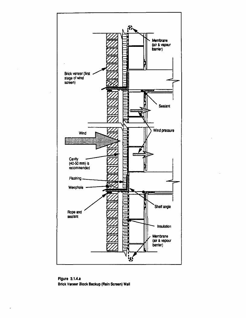
These materials have a high resistance to air leakage but they also fall generally into two groups: Sheet membranes and Iiquid applied membranes do not have the structural properties to transfer pressure loads directly to the supporting structure and generally must be supported by a masonry or board substrate. Sheet membranes usually consist of prefabricated flexible, modified bituminous sheets. They are installed by heat fusing, self-adhesive or as separately adhered system with ail laps sealed. Commonly used in masonry construction where blocks, columns and membranes work together to create a continuous structural plane of air-tightness. Liquid applied membranes are trowel or spray applied to masonry surfaces to form a continuous monolithic film. The membrane cures to provide a flexible, elastic film with crack bridging capabilities. They are particularly suitable for applications where sheet materials are awkward to cut and fit such as around brick ties. In general, they are located within the wall assembly as components of "non-accessible" air barrier systems. As an example, consider their use in brick veneer and con crete block walls. Fig.3.1.4.a.
Brick veneer is a very popular cladding material. It can be applied over steel stud or concrete block back-up-walls.
Concrete block masonry by itself offers very little resistance to the passage of air, heat, water vapour, or Iiquid water. It does have considerable storage capa city for heat and moisture. Its most important function is to provide support for the brick veneer and the insulation, air and vapour seals and finishes. Its ability to resist lateral loads is limited 50, beyond a certain length, it must be stabilized at regular intervals with pilasters or intersection walls. It should be noted that with a good air barrier, the back-up walls'
3-3
Brick veneer (filS! stage of wind sereen)
Cavity (40-50 mm) is recommended
Flashing ------i~~oFII Weephole ---~'SQ
Ropeand seatan!
FIgure 3.1A •• Brick Veneer Block Backup (Rain Screen) Wall
Membrane (air & vapeur barrier)
Seafant
angle
Insufation
Membrane (air & vapeur barrier)
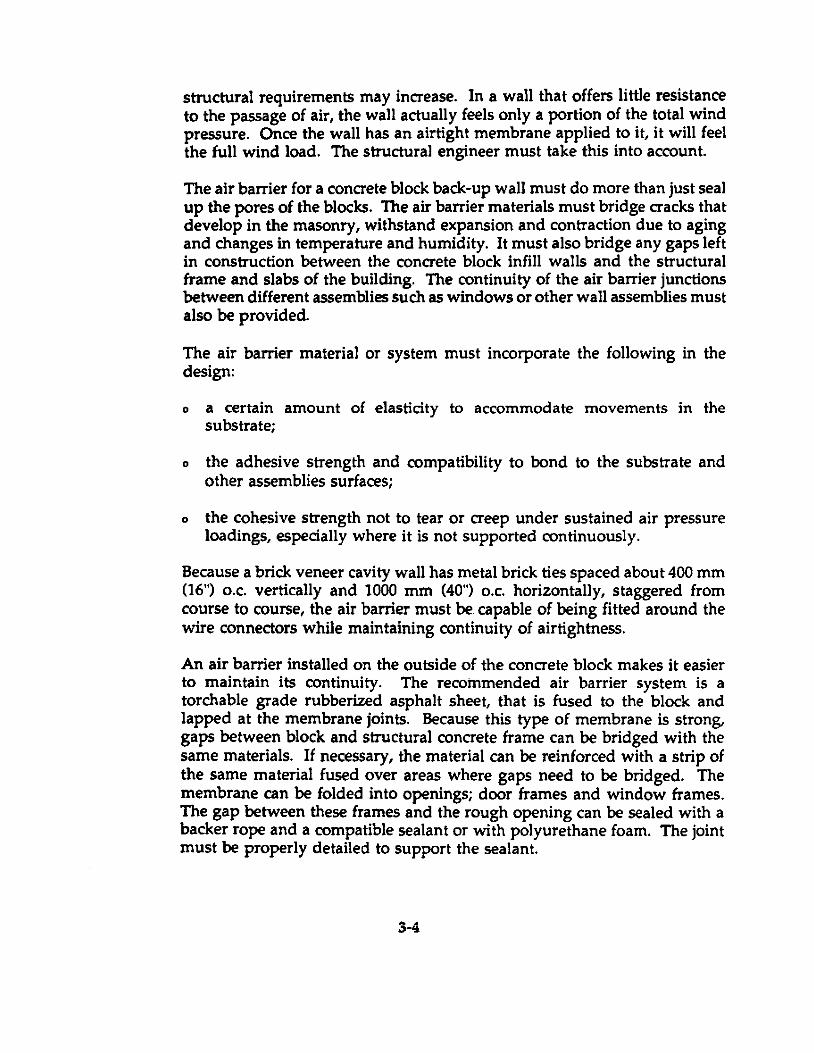
structural requirements may increase. In a wall that offers littIe resistance to the passage of air, the wall actually feels only a portion of the total wind pressure. Once the wall has an airtight membrane applied to it, it will feel the full wind load. The structural engineer must take this into account.
The air barrier for a concrete black back-up wall must do more than just seal up the pores of the blacks. The air barrier materials must bridge cracks that develop in the masonry, withstand expansion and contraction due to aging and changes in temperature and humidity. It must also bridge any gaps left in construction between the con crete block infill walls and the structural frame and slabs of the building. The continuity of the air barrier junctions between different assemblies such as windows or other wall assemblies must also be provided.
The air barrier material or system must incorporate the following in the design:
o a certain amount of elasticity to accommoda te movements in the substrate;
othe adhesive strength and compatibility to bond to the substrate and other assemblies surfaces;
othe cohesive strength not to tear or creep under sustained air pressure loadings, especially where it is not supported continuously.
Because a brick veneer cavity wall has metal brick ties spaced about 400 mm 06") o.c. vertically and 1000 mm (40") o.c. horizontally, staggered from course to course, the air barrier must be. capable of being fitted around the wire connectors while maintaining continuity of airtightness.
An air barrier installed on the outside of the con crete block makes it easier to maintain its continuity. The recoinmended air barrier system is a torchable grade rubberized asphalt sheet, that is fused to the black and lapped at the membrane joints. Because this type of membrane is strong, gaps between block and structural concrete frame can be bridged with the same materials. If necessary, the material can be reinforced with a strip of the same material fused over areas where gaps need to be bridged. The membrane can be folded into openings; door frames and window frames. The gap between these frames and the rough opening can be sealed with a backer rope and a compatible sealant or with polyurethane foam. The joint must be properly detailed to support the sealant.
3-4
Other types of membrane available incJude polyethylene sheet, spun bonded polyolefin membrane, EPDM sheets, but yI, polyvinyl chloride. AU of these membranes must generaUy be supported by a substrate such as masonry or a board product.
3.2. PrimaIT Air Barriers (RiSid)
These materials and systems (prefabricated assemblies) have sufficient strength and stiffness to be fastened to an intermediate support or directly to the primary structure of the building. They are generaUy air impermeable and have selfsupporting structural properties.
3.2.1. Materials
Materials that qualify incJude:
o Cast-in-place Con crete o Precast Concrete o Gypsum Board Products o Plywood and ParticJe Boards o Sheet Steel o Glass
Where these materials form part of an air barrier system, the performance of the system will depend strongly on the sealants and gaskets used to main tain continuity between elements.
The foUowing examples describe how an air barrier can be achieved using gypsum board.
Two different techniques are used. Their essential difference is in the locations of the plane of airtightness.
- the Accessible DrywaU approach, and - the Non-accessible DrywaU Approach.
3.2.1.1. Accessible Drywall Approach
In the Accessible Drywall Approach, the interior (exposed) layer of gypsum board constitutes the main component of the air barrier system. The joints between boards are taped and finished and high performance sealants or gaskets are used to seal the gypsum board
3-5
to other materials. The Accessible Drywall Approach offers the advantage of providing easy access to the air barrier from the interior, providing for easy inspection and repairs.
The Accessible Drywall Approach works weil with ail concrete structures. A variety of air seal materials can be used to seal the gypsum board to the concrete floor and to the underside of the slab (Fig. 3.2.1.1.a). Since the concrete floor itself is virtually Impermeable to air, it ensures the continuity of the air barrier through its thickness. In areas where more air movement is anticipated such as the interface between gypsum board and concrete slab cei1ing, a strip of reinforced elastomeric membrane is often used. A suggested detail for the air barrier continuity at party wall connections is provided in Fig. 3.2.1.1.b.
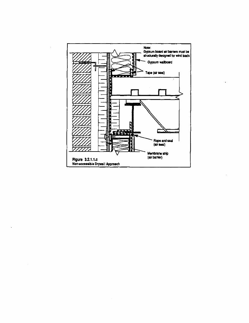
In a steel structure, achieving an airtight enclosure with the Accessible Drywall Approach may be complicated. It is difficult to achieve a durable seal between the wall air barrier and the metal deck or spandrel beam/column intersection. In this case, to facilitate achievement of continuity of the plane of airtightness, the Non-accessible Drywall Approach is often the better option (Fig. 3.2.1.1.c).
3.2.1.2. Non-Accessible Drywall Approach
In this system, gypsum board sheathing is the main component of the air barrier system. The joints between boards are taped with a reinforced self-adhesive tape, and joints between the boards and other components are sealed using strips of elastomeric membrane. If aluminum foil backed gypsum board is used, the foil should face the inside stud cavity as the sealant and strips of elastomeric membrane adhere better to the paper liner than foil. To avoid condensation problems, insulation should be fastened to the outside of the gypsum board not inside the stud cavity.
This approach usually requires fewer penetrations than the Accessible Drywall Approach (outlet boxes, supply piping, and wiring to mechanical services, etc.). Brick ties are the main penetration. The externallocation is particularly advantageous with a steel structure because the air barrier can usually be extended past the steel columns and floors with few complications.
3-6

Figure 3.2.1.1.8 Accessible Drywall Approlch
Pian viaw
Extarior ctadcling • Cavity
Ext.rior Insulation • Metal stud wall·
Palyllhal8nt (lAIpOur retardar) • DrywaJl (air barrier)·
<0 Suitablefor ... V .J Construction
Figure 3.2.1.1.b Air barri.r Drywall Aero .. Ptrty Will
Go Suitable for ... V .J Construction
Gypsum WIIlboard
Not.: ayplum board IIr barrltrs must b. Itructurally dHlgnecl Ior wlnd IDeels
Concret. ftocr sIab
Alrseal
• Brick vener • Cavity (SO· 75 mm)
.--1 • Rlgid Insulation • Balt ilsulalion and sl"1 stucl • PoIyelhylene (vapuor retarder • Gypsum board (u banier)
Gypsum board (air barrier)
Nole:
-.,,"777"'T'l.,....,..-......... r-c'~c::.=::1;r- Gypsum bo8ftj lir ~rs must be 1.. slNCIUrIIIy designed !or wind Ioads
Figure 3.2.1.1.c Non .. cc..liblt Drywall Approech
Gypsum waliboard
Tape (u seaJ)
Rcpe and saaI (liroeaJ)
Membrane~ (air barrier)
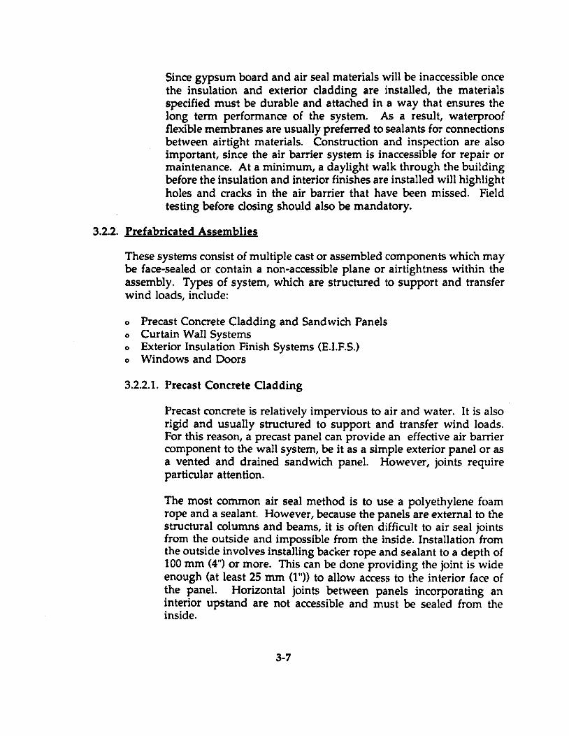
Since gypsum board and air seal materials wi11 be inaccessible once the insulation and exterior c1adding are installed, the materials specified must be durable and attached in a way that ensures the long term performance of the system. As a result, waterproof flexible membranes are usually preferred to sealants for connections between airtight materials. Construction and inspection are also important, since the air barrier system is inaccessible for repair or maintenance. At a minimum, a daylight walk through the building before the insuJation and interior finishes are installed will highlight holes and cracks in the air barrier that have been missed. Field testing before cJosing should also be mandatory.
3.2.2. Prefabricated Assemblies
These systems consist of multiple cast or assembled components which may be face-sealed or contain a non-accessible plane or airtightness within the assembly. Types of system, which are structured to support and transfer wind loads, inc1ude:
o Precast Concrete Cladding and Sandwich Panels o Curtain Wall Systems o Exterior Insulation Finish Systems (E.I.F.S.) o Windows and Doors
3.2.2.1. Precast Concrete Cladding
Precast con crete is relatively impervious to air and water. It is also rigid and usually structured to support and transfer wind loads. For this reason, a precast panel can provide an effective air barrier component to the wall system, be it as a simple exterior panel or as a vented and drained sandwich panel. However, joints require particular attention.
The most common air seal method is to use a polyethylene foam rope and a sealant. However, because the panels are external to the structural columns and beams, it is often difficult to air seal joints from the outside and impossible from the inside. Installation from the outside involves installing backer rope and sealant to a depth of 100 mm (4") or more. This can be done providing the joint is wide enough (at least 25 mm (1 ")} to allow access to the interior face of the panel. Horizontal joints between panels incorporating an interior upstand are not accessible and must be sealed from the inside.
3-7
Installation of the air seal from the inside gives hetter access to most of the joint lengths except where spandrel heams, floor slabs and columns are in the way. These obstructions can represent a considerable proportion of joint length. Ta a certain extent; this problem can he reduced by the design of the panels, but it will never he eliminated. ln the case of such obstructions, it is usually necessary to seal the gap between the panel and the structural framework of the building. This often does not pro vide a complete solution either hecause vertical building services such as ductwork or piping are often located at the perimeter of the building.
The choice of a precast c1adding system and its detailing should be influenced by the ease with which the air barrier system can be installed. Contractor should demand a detailed explanation of the air barrier installation system from the architect.
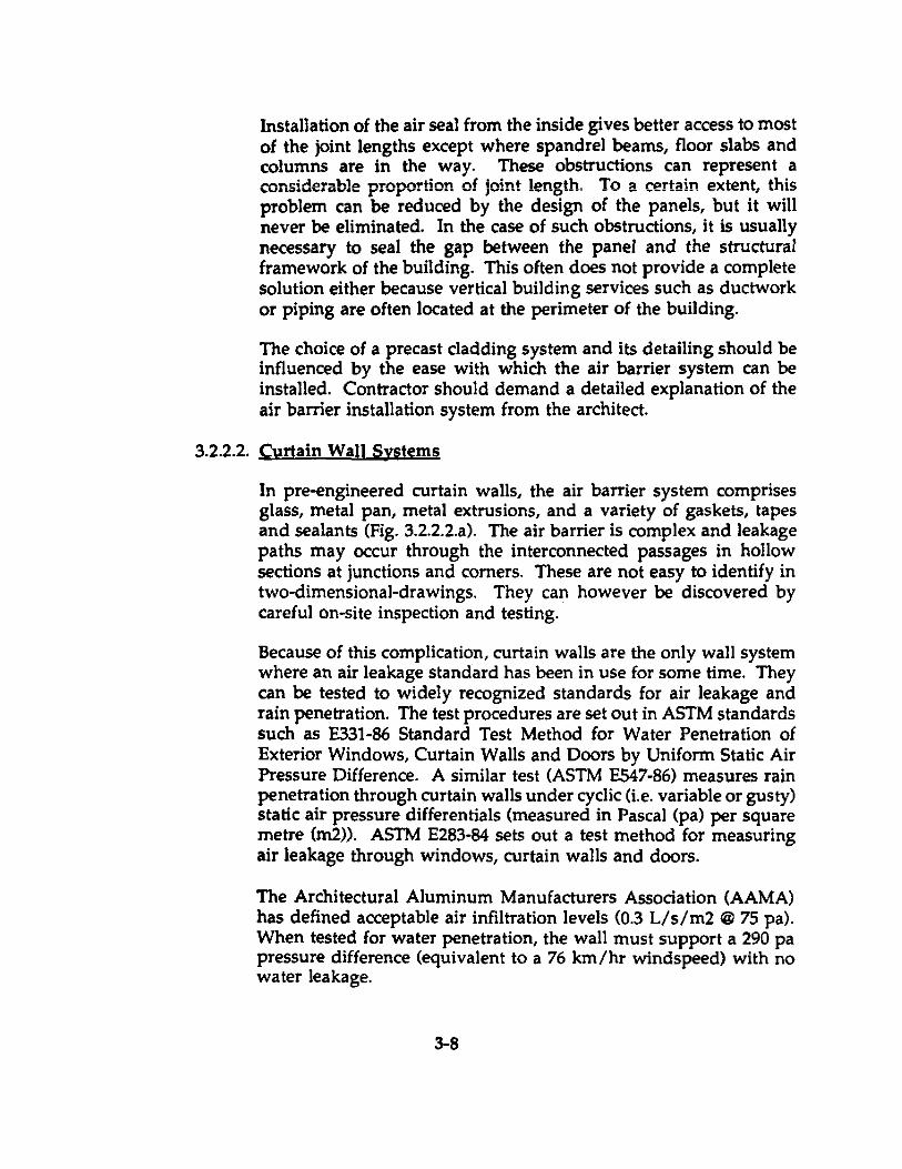
3.2.2.2. Curtain Wall Systems
In pre-engineered curtain walls, the air barrier system comprises glass, metal pan, metal extrusions, and a variety of gaskets, tapes and sealants (Fig. 3.2.2.2.a). The air barrier is complex and leakage paths may occur through the interconnected passages in hollow sections at junctions and corners. These are not easy to identify in two-dimensional-drawings. They can however he discovered by careful on-si te inspection and testing.
Because of this complication, curtain walls are the only wall system where an air leakage standard has been in use for some time. They can he tested to widely recognized standards for air leakage and Tain penetration. The test procedures are set out in ASTM standards such as E331-86 Standard Test Method for Water Penetration of Exterior Windows, Curtain Walls and Doors by Uniform Static Air Pressure Difference. A similar test (ASTM E547-86) measures Tain penetration through curtain walls under cyclic (i.e. variable or gusty) static air pressure differentials (measured in Pascal (pa) per square metre (m2». ASTM E283-84 sets out a test method for measuring air leakage through windows, curtain walls and doors.
The Architectural Aluminum Manufacturers Association (AAMA) has defined acceptable air infiltration levels (0.3 L/s/m2 @ 75 pa). When tested for water penetration, the wall must support a 290 pa pressure difference (equivalent to a 76 km/hr windspeed) with no water leakage.
3-8
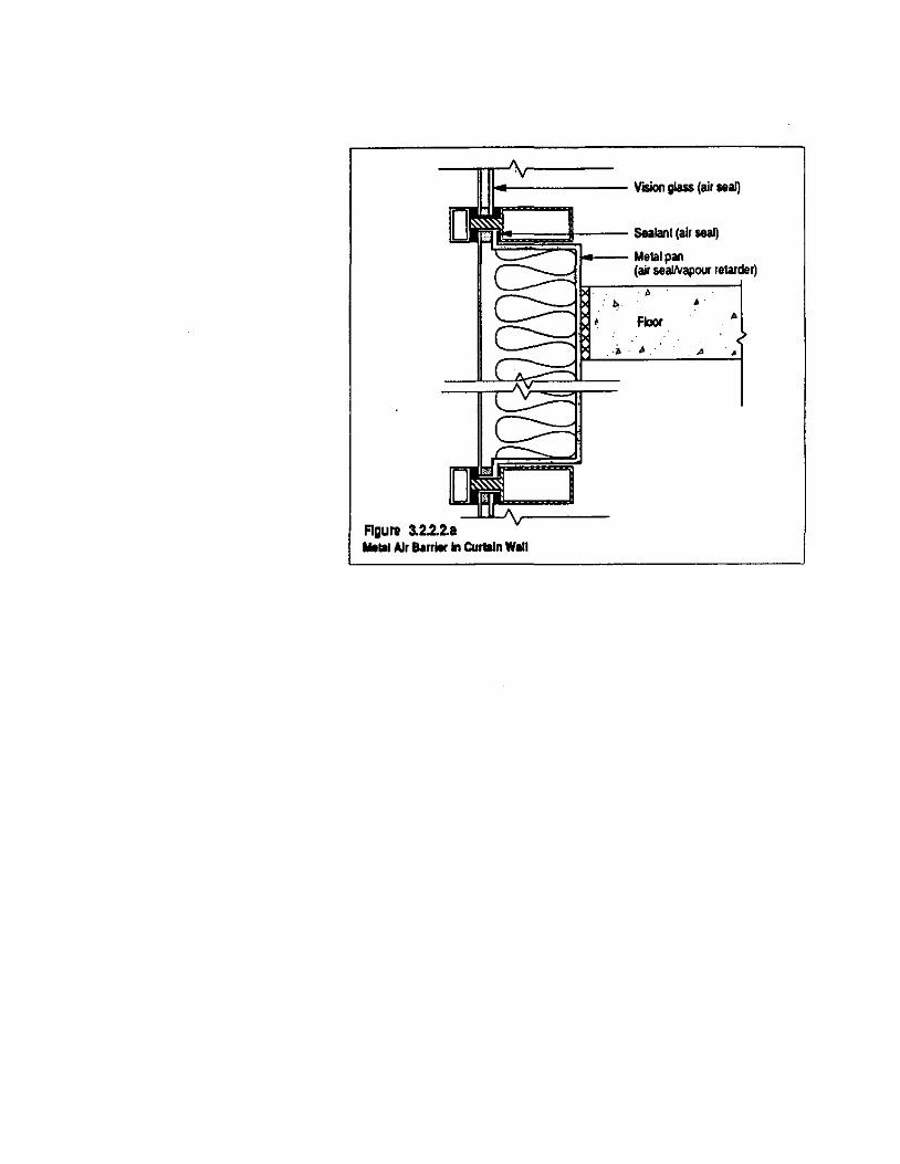
It------- VISion glass (air 18a1)
~~~~~== Sealanl (air seaI) '\ Metal pan
(air seallvapollr retarder)
b • Floor •
.. • ~
Figure 3.2.2.2.8 Mellol Air Barrier ln CUrl8ln Will
Most Canadian curtain wall systems easily meet these requirements. In fact, most systems have one third to one quarter the air leakage called for by AAMA. Test results are usually available for standard systems. Custom systems must be tested. The Institute for Research In Construction (IRC) at the National Research Coundl (NRC) has developed graded air leakage requirements. These could be applied where greater control is required as would be the case for high humidity buildings or for particularly severe exposures.
The requirements for airtightness and vapour diffusion control are met by most curtain wall systems because of the inherent properties of glass, aluminum tubing and steel panels that comprise the system. Leakage of air and water occurs most commonly at expansion joints in mullions, at intersections of rails and mullions (four way joints) and along members subject to excessive deflection. Sorne mu Ilion and rail systems are made up of Iwo components and are known as split mullion systems. The screw chases required in these members tend to leak, and they have no sealed thermal break.
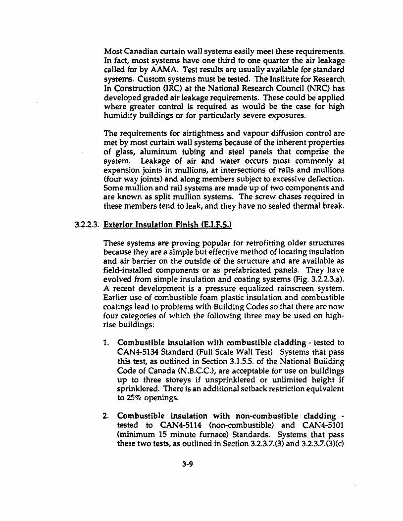
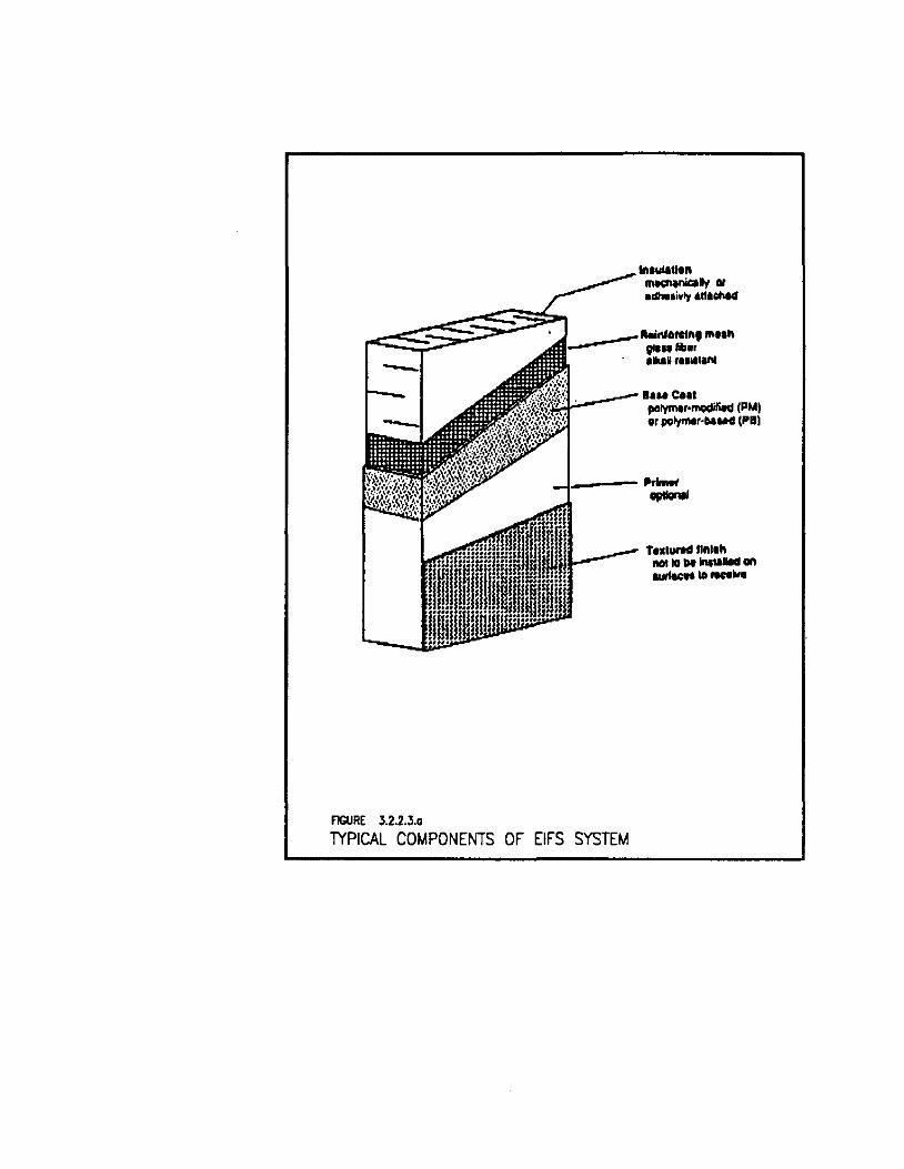
3.2.2.3. Exterior Insulation Finish Œ.I.F.S.l
These systems are proving popular for retrofitting older structures because they are a simple but effective method of locating insulation and air barrier on the outside of the structure and are available as field-installed components or as prefabricated panels. They have evolved from simple insulation and coating systems (Fig. 3.2.2.3.a). A recent development is a pressure equalized rainscreen system. Earlier use of combustible foam plastic insulation and combustible coatings lead to problems with Building Codes so that there are now four categories of which the following three may be used on highrise buildings:
1. Combustible insulation with combustible c1adding - tested to CAN4-5134 Standard (Full Scale Wall Test). Systems that pass this test, as outlined in Section 3.1.5.5. of the National Building Code of Canada (N.B.C.C.), are acceptable for use on buildings up to three storeys if unsprinklered or unlimited height if sprinklered. There is an additional setback restriction equivalent to 25% openings.
2. Combustible insulation with non-combustible cladding -tested te CAN4-5114 (non-combustible) and CAN4-5101 (minimum 15 minute fumace) Standards. Systems !hat pass these two tests, as outlined in Section 3.2.3.7.(3) and 3.2.3.7.(3)(c)
3-9
AGURE 3.2-2.3.0
.... wIaU.n _ .... 1Iy III
.nliwtr .. na0nt4
.... e .. , porym.,·lIIOCIiliW (PMI or poly ... r'lIIud (PBI
-1.----gptIanII
__ ~ T ... ,urH fllllth ,~ "'" ID III ''''101I00I an
~10""1woo
IYPICAL COMPONENTS OF EIFS SYSTEM
of the N.B.C.C., are acceptable for use on buildings required to be of non-combustible construction without height restrictions. There is a setback restriction equivalent to 25% openings.
3. Non-combustible insulation with non-combustible cladding. These types of systems meet the N.B.C.C. with no code restrictions.
The Rainscreen system (Fig. 3.2.2.3.b.) developed over the last year meets al! N.B.C.C. requirements and has been tested successfully to meet ASTM E 283, E 330, E 331 and E 547 standards.
Air leakage of the assembly was 0.007 L/S/m2 at 75 pa. and .025 L/S/m2 at 300 pa.
When using such systems, it will be important for the designer to carry out a Oew-Point assessment to avoid risk of moisture problems within the wall.
3.2.2.4. Windows and Ooors
Glazing and exterior doors form good air barrier components. Care must be taken in the continuity and quality of the connection of their frames to the wall air barrier system. Adhered Membranes or One Component Polyurethane Foam are the usual materials for sealing these gaps that will occur.
The quality of the air barrier system within the frames and sashes of glazing system is also of con cern since both form part of the air barrier system. There is a performance standard, CAN ICSA-A440-M90, which stipula tes maximum allowable air leakage rates per unit of crack length measured at 75 pa pressure, for different criteria of window use. The aJJowable rates are as follows:
Wlndow Rating Lrvel of Performance Selection Criteria
Storm Maximum Air Leakage Rate -(m3/h.) mol 8.35 (max) 5.00 (min)
3-10
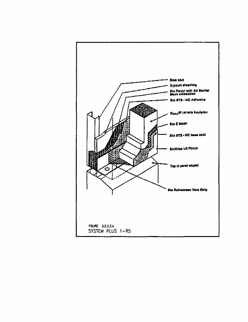
FIGURE J.2.2.J.b
_-------- StHl ,QJd
__ -------:: Gyp ........... 1IIing -=-_------ 110 ~..,I .11" AIIS...c. _ "'oh .mH~d'" ..-_~----- SIO STB· Ne ,ldheol ••
SIOE"'I/I
SI" 81'S -IIC "" .. "al
lIOBII .. Ull'1lllll\
Top of I*'8ll1Oped
SYSTEM PLUS 1-RS
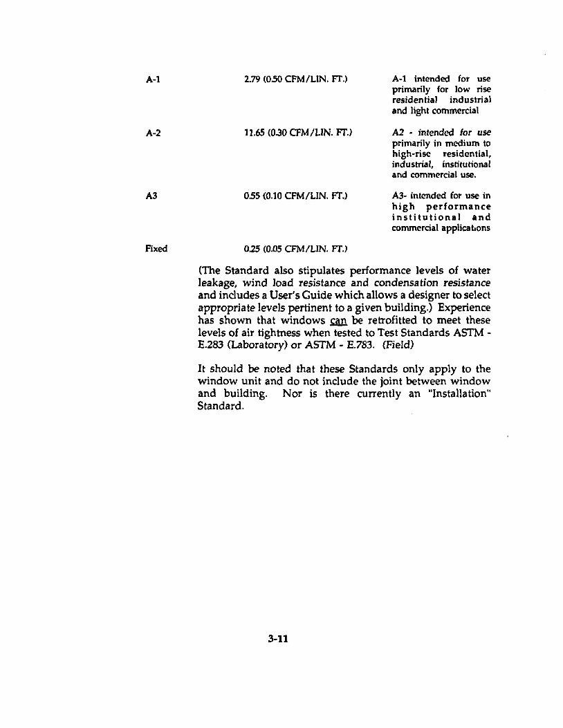
A-t
A-2
A3
Fixed
2.79 (0.50 CFM/LIN. fT.)
11.65 (0.30 CFM/LIN. FT.)
055 (0.10 CFM/LIN. fT.)
0.25 (0.05 CFM/LIN. fT.)
A-t intended for use primarily for low rise residentia\ industrial and Iight commercial
A2 - intended lor use primarily in medium to high-rise residential, industrial, institutional and commercial use.
Al- intcoded for use in high performance institutional and commercial applicabons
(The Standard also stipula tes performance levels of water leakage, wind load resistance and condensation resistance and includes a User's Guide which allows a designer to select appropria te levels pertinent to a given building.) Experience has shown that windows can be retrofitted to meet these levels of air tightness when tested to Test Standards ASTM -E.283 (Laboratory) or ASTM - E.783. (Field)
It should be noted that these Standards only apply to the window unit and do not include the joint between window and building. Nor is there currently an "Installation" Standard.
3-11
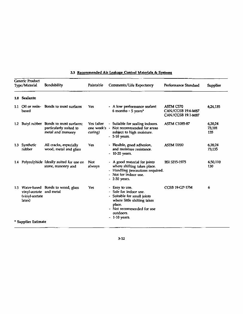
3.3 Recommended Air Leakage Control Materials 8t Systems
Generic Product Type/Material Bondability Pain table Comrnents/Life Expectancy Perfonnanœ Standard
1.0 Sealants:
1.1 Oil or resin- Bonds to rnost surfaces Yes - A low perfonnance sealant 6 months - 5 years·
ASTM C570 CAN/CGSB 19.6-M87 CAN/CGSB 19.1-M87
based
1.2 But yi rubber Bonds to rnost surfaœs; particularly suited to metal and masonry
1.3 Synthetic rubber
Ali cracks, especially wood, metal and glass
1.4 Polysulphide Ideally suited for use on stone, rnasonry and
1.5 Water-based Bonds to wood, glass vinyl-acetate and metal (vinyl-acetate latex)
• Supplier Estimate
Yes (after - Suitable for sealing indoors. one week's - Not recornrnended for areas curing) subject to high moisture.
Yes
- 5-10 years.
- Flexible, good adhesion, and rnoisture resistanœ.
- 10-20 years.
ASTM CI085-87
ASTM 0200
Not always
- A good rnaterial for joints BSt 5215-1975
Yes
where shifting takes plaœ. - Handling precautions required. - Not for indoor use. - 2-30 years.
- Easy to use. CGSB 19-GP-17M - Safe for indoor use. - Suitable for small joints
where little shifting takes place.
- Not recornrnended for use outdoors.
- 1-10 years.
3-12
Supplier
6,24,135
6,20,24 73,101 135
6,20,24 73,135
6,50,110 130
6
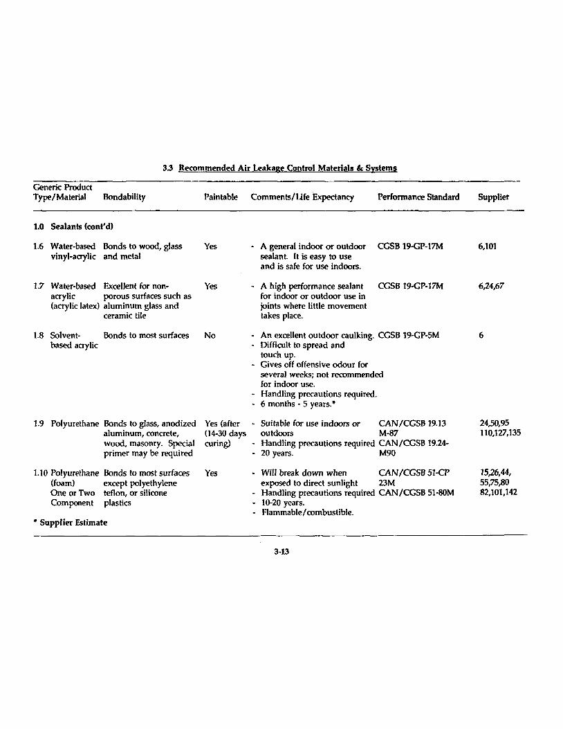
3.3 Recommended Air Leakage Control Materials & Systems
Generic Product Type/Material Bondability Pain table Comments/Life Expectancy Perfonnance Standard
1.0 Sealants (cont'd)
1.6 Water-based Bonds to wood, glass Yes vinyl-acrylic and metal
1.7 Water-based Excellent for non- Yes acrylic porous surfaces such as (acrylic latex) aluminum glass and
ceramic tile
1.8 Solvent- Bonds to Most surfaces based acrylic
1.9 Polyurethane Bonds to glass, anodized aluminum, con crete, wood, masonry. Special primer May he required
1.10 Polyurethane Bonds to most surfaces (foam) except polyethylene One or Two tenon, or silicone Component plastics
.. Supplier Estimate
No
Yes (after (14-30 days curing)
Yes
- A general indoor or outdoor CCSB 19-GP-17M sealant. It is easy to use and is safe for use indoors.
- A high performance sealant ceSB 19-GP-17M for indoor or outdoor use in joints where IiUle movement takes place.
- An excellent outdoor caulking. CCSB 19-GP-5M - Difficult to spread and
touch up. - Cives off offensive odour for
several weeks; not recommended for indoor use.
- Handling precautions required. - 6 months - 5 yeaTs."
- Suitable for use indoors or CAN/CCSB ]9.13 outdoors M-87
- Handling precautions required CAN/CCSB 19.24-• 20 years. M90
- Will break down when CANICGSB 51-CP exposed to direct sunlight 23M
- Handling precautions required CAN/CCSB 51-SOM - 10-20 years. - F1ammable / combustible .
3-13
Supplier
6,101
6,24,67
6
24,50,95 110,127,135
15,26,44, 55,75,80 82,101,142
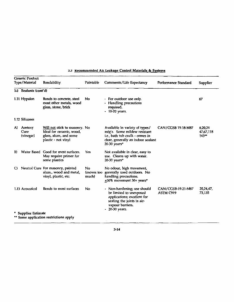
3.3 l{eCommended Air Leakage Control Materials &: Systems
Generic Product Type/Material Bondability Pain table Comments/Ufe Expectancy Performance Standard
1.0 Sealants (cont'd)
1.11 Hypalon Bonds to concrete, steel No
1.12 Silicones
Most other metals, wood glass, stone, brick
A) Acetoxy Cure (vinegar)
Will not stick to masonry. No Ideal for ceramic, wood, glass, alum, and some plastic - not vinyl
Bl Water Based Good for most surfaces. May require primer for some plastics
C) Neutra! Cure For masonry, painted alum., wood and metal, vinyl, plastic, etc.
1.13 Acoustical Bonds to Most surfaces
• Supplier Estimate .. Sorne application restrictions apply
Yes
No (moves too much)
No
- For outdoor use only. - Handling precautions
required. - 10-20 years.
Available in variety of typesl CAN/CGSB 19.18-M87 mfg's. Some mildew resistant i.e., bath tub caulk - cornes in c1ear, generally an indoor sealant 20-30 years·
Not available in c1ear, easy to use. Cleans up with water. 20-30 years·
No odour, high movement, generally used outdoors. No handling precautions. ±50% movement 30+ years·
- Non-hardening; use should he limited to unexposed applications; excellent for sealing the joints in airvapour barrieTs.
- 20-30 years.
3-14
CAN ICGSB-19.21-M87 ASTM C919
Supplier
67
6,20,24 47,67,118 143··
20,24,47, 73,135
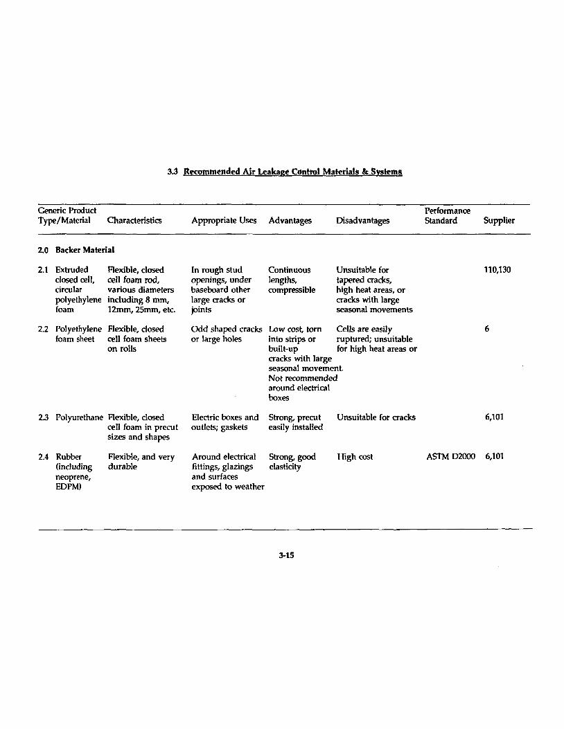
3.j Recommended Air Leakage Control Materiats &: Systems
Generic Product Performance Type/Material Characteristics Appropriate Uses Advantages Disadvantages Standard Supplier
2.0 8acker Material
2.1 Extruded Flexible, closed ln rough stud Continuous Unsuitable for 110,130 c10sed œil, œil foam rod, openings, under lengths, tapered cracks, cirrolar various diameters baseboard other compressible high heat areas, or polyethylene inc1uding 8 mm, large cracks or cracks with large foam 12mm, 25mm, etc. joints seasonal movements
2.2 Polyethylene Flexible, c10sed Odd shaped cracks Low cost, torn Cells are easily 6 foam sheet cell foam sheets or large holes into strips or ruptured; unsuitable
on rolls built-up for high heat areas or cracks with large seasonal movement. Not recommended around electrical boxes
2.3 Polyurethane Flexible, c10sed E1ectric boxes and Strong, prerot Unsuitable for cracks 6,101 œil foam in precut outlets; gaskets easily installed sizes and shapes
2.4 Rubber Flexible, and very Around electrical Strong, good High cost ASfM 02000 6,101 (inc1uding durable fi ttings, glazings elasticity neoprene, and surfaces EDPM) exposed to weather
3-15

3.3 Kecommended Air Leakage Control Materials &: Systems
Generic Product Type/Material Characteristics
2.0 8acker Material (cont'd)
2.5 Oakum
2.6 Fibreglass
2.7 Pyrofite Perlite Ceramic Treated Fireproofl Moisture proof
Fibrous, tar soaked hemp
Scraps of fibreglass batt
Spray applied for loos fill
Appropriate Uses Advantages
Rough masonry, irregular cracks
Filling amount window and door jambs
Lost rost; easily worked into irregular cracks
Lost rost; easily worked into irregular cracks
Window and door Medium rost; jams will not absorb
moisture. Bonds weil
3-16
Disadvantages
Poor elastidty, may leak air and absorb water, will allow sealant bonding and should not be used as backing
Performance Standard Supplier
Rarely used. May be found in Heritage building retrofit situations
Poor elastidty, may CSA 101-M 21,60 leak air and absorb water, will allow sealant bonding and should not be used as backing
101
3.3 Recommended Air Leakage Control Materlals &: SI§tems
Generic Product Performance Type/Material Durability Application Performance Comments Standard Supplier
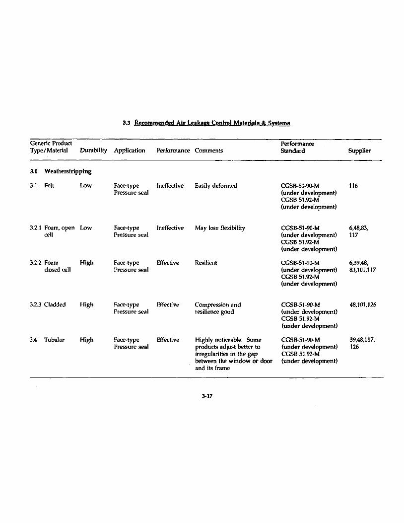
3.0 Weatherstripping
3.1 Felt Low Faœ-type Ineffecti ve Easily deformed CGSB-51-90-M 116 Pressure seal (under development)
CGSS 51.92-M (under development)
3.2.1 Foarn, open Low Face-type Ineffective May lose f1exibility CGSB-51-90-M 6,48,83, cell Pressure seai (under development) 117
CGSS 51.92-M (under development)
3.2.2 Foarn High Face-type Effective Resilient CGSB-51-90-M 6,39,48, closed cell Pressure seal (under development) 83,101,117
cess 51.92-M (under development)
3.2.3 Cladded High Face-type Effective Compression and CeSB-51-90-M 48,101,]26 Pressure seal resilience good (under development)
CGSS 51.92-M (under development)
3.4 Tubular High Face-type Effective Highly noticeable. Sorne CGSB-51-90-M 39,48,117, Pressure seal products adjust better to (under development) 126
irregularities in the gap CGSB 51.92-M between the window or door (under development) and its frame
3-17
3.3 Recommended Air Leakage Control Materials &: Systems
Generic Product Performance Type/Material Durability Application Performance Commenfs Standard Supplier
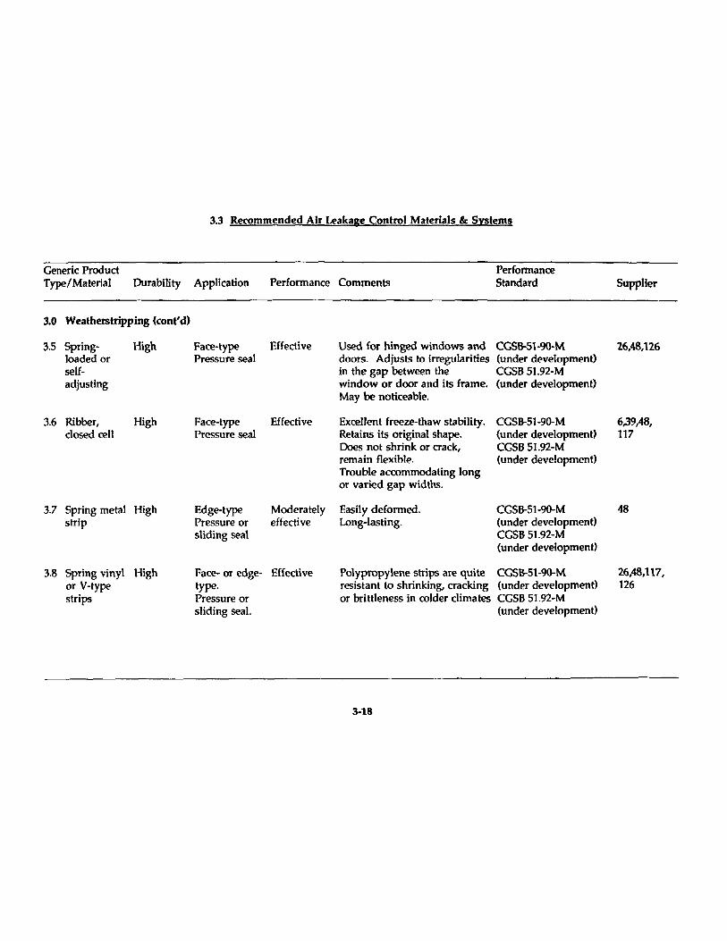
3.0 Weatherstripping (cont'd)
3.5 Spring- High Face-type Effective Used for hinged windows and CGSB-51-90-M 26,48,126 loaded or Pressure seal doors. Adjusts to irregularities (under development) self- in the gap between the CGSB 51.92-M adjusting window or door and ifs frame. (under developmenO
May be noticeable.
3.6 Ribber, High Face-type Effective Excellent freeze-thaw stability. CGSB-51-90-M 6,39,48, c10sed œil Pressure seal Retains ifs original shape. (under development) 117
Does not shrink or crack, CGSB 51.92-M remain flexible. (under developmenO Trouble accommodating long or varied gap widths.
3.7 Spring metal High Edge-type Moderately Easily deformed. CGSB-51-90-M 48 strip Pressure or effective Long-lasting. (under development)
stiding seal CGSB 51.92-M (under developmenO
3.8 Spring vinyl High Face- or edge- Effective Polypropylene strips are quite CGSB-51-90-M 26,48,117, or V-type type. resistant to shrinking, cracking (under developmenO 126 strips Pressure or or brittleness in colder dimates CGSB 51.92-M
sliding seal. (under development)
3-18
3.3 Recommended Air leakage Control Materials &: Systems
Generic Product Type/Material Durability Application Performance Comments
Performance Standard
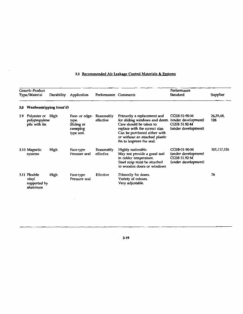
3.0 Weatherstripping (cont'd)
3.9 Polyester or High polypropylene pile with fin
3.1 0 Magnetic systems
High
3.11 Flexible High vinyl supported by aluminum
Face- or edgetype. Sliding or sweeping type seaL
Face-type Pressure seal
Reasonably effective
Reasonably effective
Face-type Effective Pressure seal
Primarily a replacement seal CeSB-51-90-M for sliding windows and doors. (under development) Care should be taken to ceSB 51.92-M replace with the correct sÎZe. (under development) Can be purchased either with or without an attached plastic fin to improve the seal.
Highly noticeable. May not provide a good seal in colder temperature. Steel strip must be attached to wood en doors or windows.
Primarily for doors. Variety of calours. Veryadjustable.
3-19
CeSB-51-90-M (under development) ceSB 51.92-M (under development)
Supplier
26,39,48, 126
101,117,126
76
3.3 Recommended Air Leakage Control Materials BI: Systems
Generic Product Performance Type/Material Characteristics Appropriate Uses Advantages Disadvantages Standard Supplier
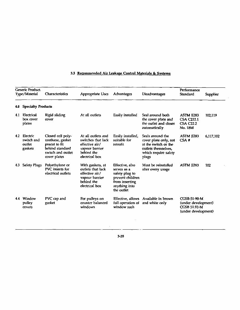
4.0 Specialty Products
4.1 Electrical Rigid sliding At ail outlets Easily installed Seal around both ASTM E283 102,119 box coyer coyer the coyer plate and CSA C222.1 plates the outIet and closes CSA C22.2
automatically No. IBM
4.2 E1ectric Closed œil poly- At ail outlets and Easily installed, Seals around the ASTM E283 6,117,102 switch and urethane, gasket switches tha t lack suitable for coyer plate only, not CSA# outIet precut to fit effecti ve air / retrofit at the switch or the gaskets behind standard vapour barrier outlets themselves,
switch and outlet behind the which require safety coyer plates electrical box plugs
4.3 Safety Plugs Polyethylene or With gaskets, at Effecti ve, al50 Must be reinstalled ASTM E283 102 PVC inserts for outlets that lack serves as a after every usage electrical outlets effective air / safety plug to
vapour barrier prevent children behind the from inserting electrical box anything into
the outlet
4.4 Window PVC cap and For pulleys on Effective, allows A vailable in brown CGSB-51-90-M pulley gasket counter balanœd full operation of and white only (under development) covers windows window sash CGSB 51.92-M
(under development)
3-20
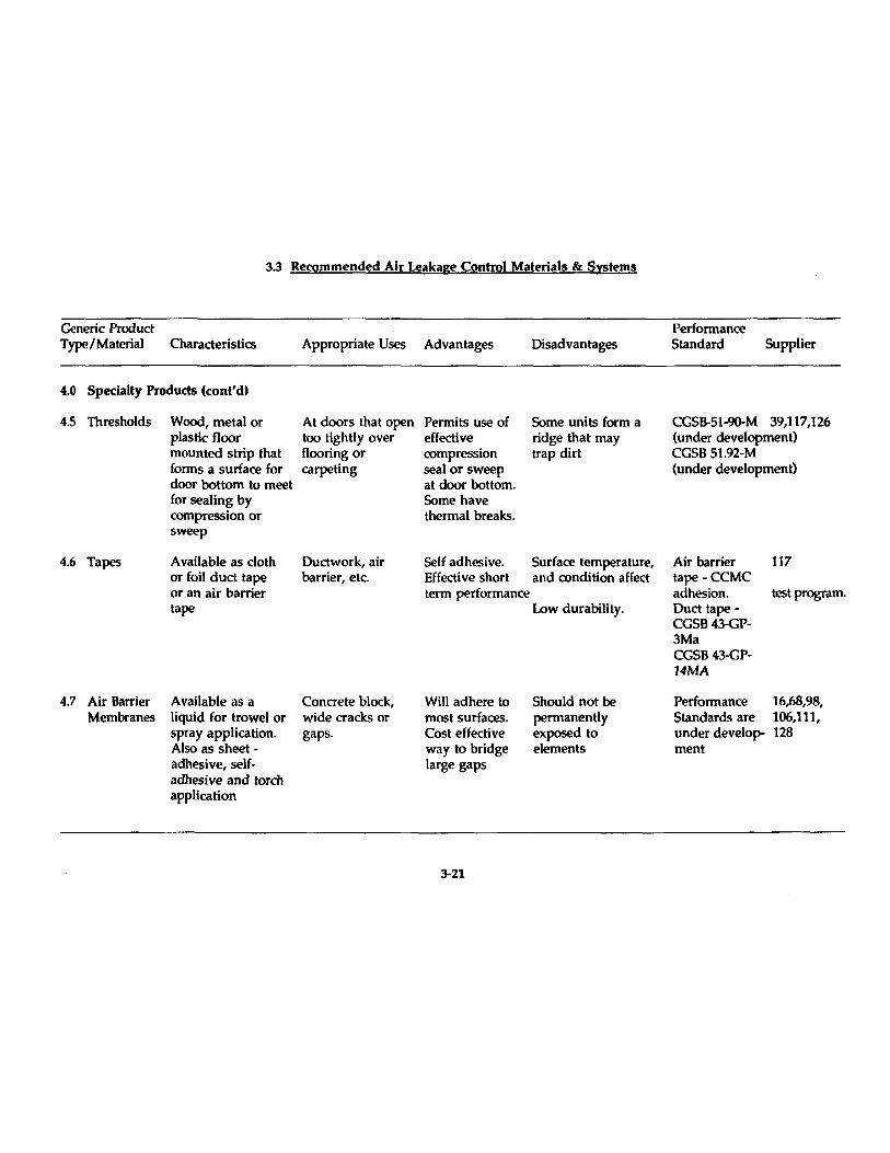
3.3 Recommended Air Leakage Control Materials & Systems
Generic Product Type/Material Characteristics
4.0 Specialty Products (cont'd)
4.5 Thresholds
4.6 Tapes
4.7 Air Barrier Membranes
Wood, metal or plastic f100r mounted strip that forms a surface for door boUom to meet for sealing by compression or sweep
Available as cIoth or foi! duct tape or an air barrier tape
Available as a liquid for trowel or spray application. Also as sheet -adhesive, selfadhesive and torch application
Appropriate Uses Advantages Disadvantages
At doors that open too tightly over flooring or carpeting
Ductwork, air barrier, etc.
Con crete block, wide cracks or gaps.
Permits use of effective compression seal or sweep at door boUom. Sorne have thermal breaks.
Sorne units form a ridge that may trap dirt
Self adhesive. Surface temperature, Effective short and condition affect terrn performance
Will adhere to most surfaces. Cost effective way to bridge large gaps
3-21
Low durability.
Should not he perrnanently exposed to elements
Performance Standard Supplier
CGSB-51-90-M 39,117,126 (under development) CGSB 51.92-M (under development)
Air barrier tape -CCMC adhesion. Duct tapeCGSB43-GP-3Ma CGSB43-GP-14MA
Performance Standards are under development
117
test program.
16,68,98, 106,111, 128
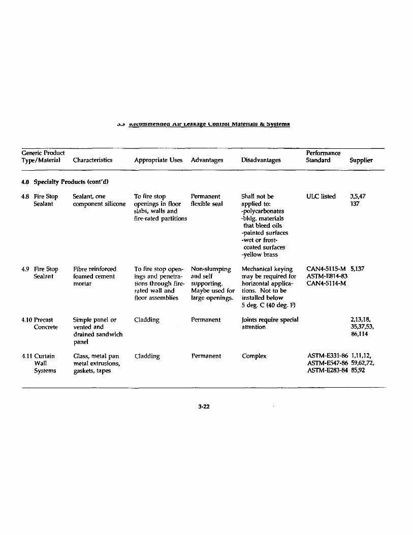
~.~ n.ecommenoeo AIr LeaKage Lontrol MaterlalS <'le 1;ystems
Generic Product Performance Type/Material Characteristics Appropriate Uses Advantages Disad vantages Standard Supplier
4.0 Specialty Produets (eonl'd)
4.8 Fire Stop Sealant, one To fire stop Permanent Shall not be ULC Iisted 3,5,47 Sealant comfXment silicone openings in floor flexible seal applied to: 137
slabs, walls and -polyearbonates fire-rated partitions -bldg. materials
that bleed ails -painted surfaces -wet or frost-coated surfaces
-yellow brass
4.9 Fire Stop Fibre reinforced To fire stop open- Non-slumping Mechanical keying CAN4-5115-M 5,137 Sealant foamed cement ings and penetra- and self may be required for ASTM-E814-83
mortar tions through fire- supporting. horizontal appliea- CAN4-5114-M rated wall and Maybe used for tions. Not to be floor assemblies large openings. installed below
5 deg. C (40 deg. F)
4.1 0 Precast Simple panel or C1adding Permanent Joints require special 2,13,18, Concrete vented and attention 35,37,53,
drained sandwich 86,114 panel
4.11 Curtain Glass, metal pan Cladding Permanent Complex ASTM-E331-86 1,11,12, Wall metal extrusions, ASTM-E547-86 59,62,72, Systems gaskets, tapes ASTM-E283-84 85,92
3-22

3.3 Recommended Air Leakage Control Materlals ok Systems
Generic Product Performance Type/Material Characteristics Appropriate Uses Advantages Disadvantages Standard Supplier
4.0 Specialty Products (conl'd)
4.12 Exterior Insulation Finish Systems (E.I.F.S.)
4.13 Insulated steel truss systems
4.14 Gypsum Board
Insulation reinforcing Cladding retrofitt- Permanent, mesh, stucoo ing older structures lightweight.
limitation of impact strength.
ASTM-E283, E330,E331 E547
Stone or granite facing, sheet steel liner, insulation
Rigid Board
Cladding
Interior Finish
Energy efficient. Variety of colour and textures.
Some systems code res trictions. Air barrier on exterior.
Steel support Care needed for system for heavy corrosion control c1addings. Cost effective
Tested by CM.H.C.
Easy access. Easy to seal joints, inspect and main tain
Vulnerable to damage Tested by CM.H.C
3-23
49,64,107, 132
9,53
22,46,142
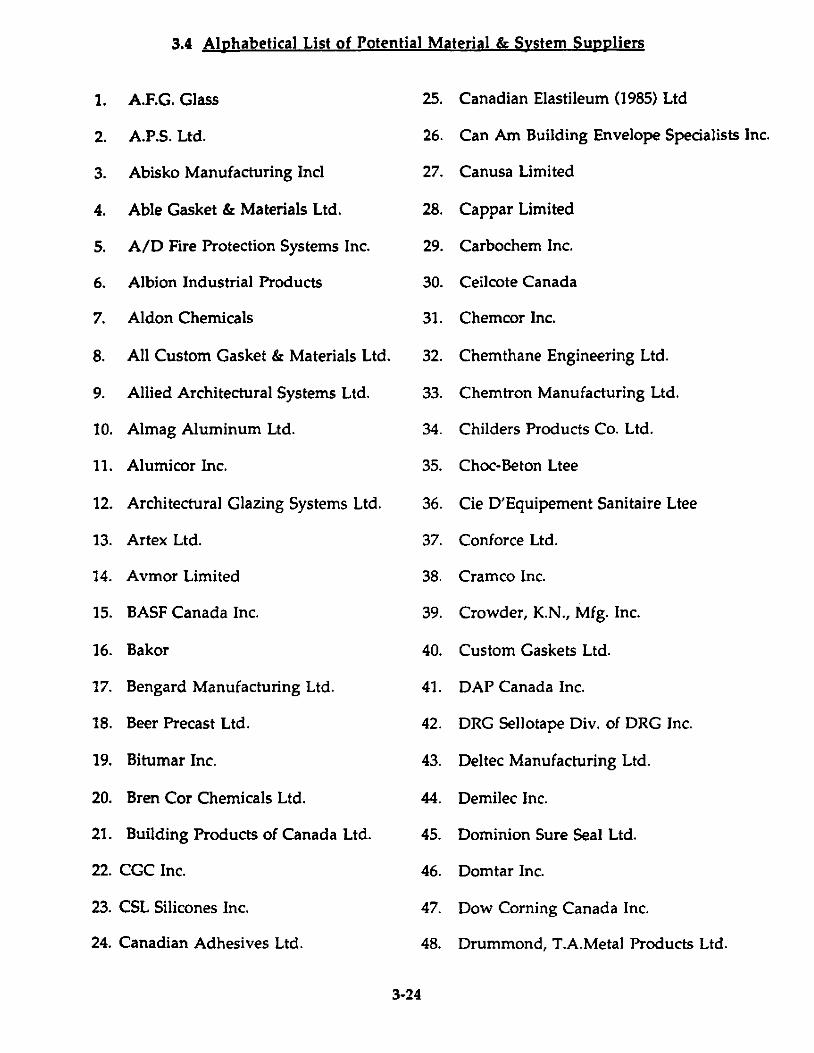
3.4 Alphabetical List of Potential Material & System Suppliers
1. AF.G. Glass 25. Canadian Elastileum (1985) Ltd
2. AP.S. Ltd. 26. Can Am Building Envelope Specialists Inc.
3. Abisko Manufacturing Incl 27. Canusa Limited
4. Able Gasket & Materials Ltd. 28. Cappar Limited
S. A/D Fire Protection Systems Ine. 29. Carbochem Ine.
6. Albion Industrial Products 30. Ceilcote Canada
7. Aldon Chemieals 31. Chemcor Ine.
8. Ali Custom Gasket & Materials Ltd. 32. Chemthane Engineering Ltd.
9. Allied Architectural Systems Ltd. 33. Chemtron Manufacturing Ltd.
10. Almag Aluminum Ltd. 34. Childers Products Co. Ltd.
11. Alumicor Ine. 35. Choc-Beton Ltee
12. Architectural Glazing Systems Ltd. 36. Cie D'Equipement Sanitaire Ltee
13. Artex Ltd. 37. Conforce Ltd.
14. Avmor Limited 38. Cramco lnc.
15. BASF Canada Inc. 39. Crowder, K.N., Mfg. Inc.
16. Bakor 40. Custom Gaskets Ltd.
17. Bengard Manufacturing Ltd. 41. DAP Canada Inc.
18. Beer Precast Ltd. 42. DRG Sellotape Div. of DRG Inc.
19. Bitumar Ine. 43. Deltec Manufacturing Ltd.
20. Bren Cor Chemicals Ltd. 44. Demilee Ine.
21. Building Produets of Canada Ltd. 45. Dominion Sure SeaI Ltd.
22. CGC Ine. 46. Domtar Ine.
23. CSL Silicones Ine. 47. Dow Corning Canada Ine.
24. Cana di an Adhesives Ltd. 48. Drummond, T.A.Metal Products Ltd.
3-24
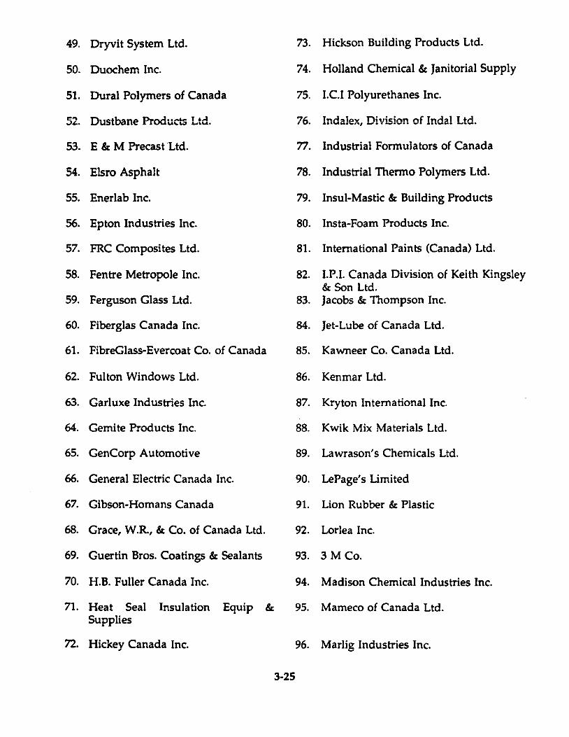
49. Dryvit System Ltd.
50. Duochem Inc.
51. Oural Polymers of Canada
52. D-üStbane Prodücts Ltd.
53. E & M PrecastLtd.
54. Elsro Asphait
55. Enerlab Inc.
56. Epton Industries Inc.
57. FRC Composites Ltd.
58. Fentre Metropole Inc.
59. Ferguson Glass Ltd.
60. Fiberglas Canada Inc.
61. FibreGlass-Evercoat Co. of Canada
62. Fulton Windows Ltd.
63. Garluxe Industries Inc.
64. Gemite Products Inc.
65. GenCorp Automotive
66. General Electric Canada Inc.
67. Gibson-Homans Canada
68. Grace, W.R, & Co. of Canada Ltd.
69. Guertin Bros. Coatings & Sealants
70. H.B. Fuller Canada Inc.
71. Heat Seal Insulation Equip & Supplies
72. Hickey Canada Inc.
3-25
73. Hickson Building Products Ltd.
74. Holland Chemical & Janitorial Supply
75. I.C.! Polyurethanes Inc.
76. Inda!ex, Division of !nda! Ltd.
77. Industrial Formulators of Canada
78. Industrial Thermo Polymers Ltd.
79. Insul-Mastic & Building Products
80. Insta-Foam Products Inc.
81. International Paints (Canada) Ltd.
82. I.P.I. Canada Division of Keith Kingsley & Son Ltd.
83. Jacobs & Thompson Inc.
84. Jet-Lube of Canada Ltd.
85. Kawneer Co. Canada Ltd.
86. Kenmar Ltd.
87. Kryton International Inc.
88. Kwik Mix Materials Ltd.
89. Lawrason's Chemicals Ltd.
90. LePage's Limited
91. Lion Rubber & Plastic
92. Lorlea Inc.
93. 3 M Co.
94. Madison Chemical Industries Inc.
95. Mameco of Canada Ltd.
96. Marlig Industries Inc.
97. McAsphalt Industries Ltd. 121. Releasall-Target International lne.
98. Meadows, W.R., of Canada Ltd. 122. Robco lne.
99. Metaltone of Canada Ltd. 123. Rochester Midland Ltd.
100. Milne, Alex, Associates Ltd. 124. Rohm & Haas Canada Inc.
101. Miraean Ontario Ltd. 125. Ross, Frank T., & Sons (1962) Ltd.
102. Molvan Enterprises Ine. 126. Schlegel Canada Ine.
103. Mulco Ine. 127. Sika Canada Ine.
104. Multiplex Chemicals Ltd. 128. Soprema
105. Ninety Eight 129. Standard Products (Canada) Ltd.
106. Nord & Bitume Ine. 130. Sternson Group
107. Ontario Panelisation Ltd. 131. Stewart Produets Ltd.
108. Ontario Rubber Div. Robeo Ine. 132. STO Industries Canada Inc.
109. Osmose-Pentox. Ine. 133. Texas Refinery Corp. of Canada Ltd.
110. PRC Canada lne. 134. Thompson, G.F., Co. Ltd.
111. PennKote Limited 135. Thoro
112. Permashell Corporation Ltd. 136. 3M Canada Inc.
113. Perma-Tae Industries Ine. 137. Tremeo Limited
114. Precon Ltd. 138. U.S.E. Chemicals
115. Proean Manufacturing Ltd. 139. Unique Sash Balance Co. Ltd.
116. Pro Form Produets Ltd. 140. Walter, E.F., Limited
117. RCR Internationallne. 141. Waterville TG Inc.
118. Rhone-Poulene Inc. 142. Westroc Industries Ltd.
119. RS Vapour 143. Zimmcor Ltd.
120. Recochem Inc.
3-26

3.5 Methods
This section identifies locations where weaknesses in the air barrier system are commonly found or inadequately detailed. Suggestions are offered for new construction detailing and also for retrofit air leakage control measures.
Sections 3.5.3. to 3.5.6. offer more practical guidelines for the Contractor dealing with operable openings and other specifie locations.
3.5.1. Be10w Grade
3.5.1.1. Conventional methods of building design/construction underestimate the significance of basement and below grade parking areas as sources of air/soil gas leakage. As with roof construction, basement details are more often concemed with waterproofing. While this is appropria te for the perimeter of foundation walls in helow grade areas, the focus of air harrier continuity shifts, at grade, from the perime ter of exterior walls above ground to the perime ter of the building core below ground.
Together with providing access to and from parking, the core gathers the various building service utilities; domestic water, waste and fire protection, gas, storm drainage, electricity, communications and garbage chutes, and directs them vertically through shafts and pipe chases for distribution. If pennitted, the Stack and Wind Effects will treat the below grade area as a weil from which air is drawn up through the building. For the air barrier system to he effective and continuous, the ground floor and below grade core areas, including below grade retai! or other commercial use areas, must be effectively isolated from below grade parking and storage areas, which are vented with unconditioned air.
3.5.1.2. Basement and Ground Floor Iunction
The junction of exterior walls, foundation and ground floor slab will be dealt with in Section 3.5.2. The balance of the ground floor may be wholly or only partIy covered by building. To main tain continuity of the air barrier system, those areas of the ground floor slab which are covered by the above grade structure must he treated as an air-tight soffit. The primary air barrier system follows the above grade envelope and tums at grade to ex tend horizontally until it reaches the perimeter of the building core. Any penetration of this soffit must not only he fire stopped but also air sealed. See Article 3.5.1.8. for pipe and duct sealing.
3-27
3.5.1.3. Building Core Walls
Core walls fonn part of the air barrier system and are often constructed of cast-in-place concrete. This choice of material satisfies structural, fire protection and air barrier concerns. If sections of the wall are concrete masonry, consideration must be given to a finish for the wall to maintain the plane of airtightness. Parging with cement mortar or application of taped and sealed gypsum board may be appropria te for both new and retrofit construction.
3.5.1.4. FJoor Slab/Wall loints
Air barrier materiais used to seal core walls must be tenninated at the junction of floor and ceiling slabs to ensure continuity. Cement parging must seal tightly at the top and bottom of the walls. Gypsum board must be caulked or foamed. Refer to Section 3.3, Sentence 1.0.
3.5.1.5. Meehanical/Eleetrical Rooms
Walls and ceilings of service rooms such as, telephone switch gear, electrical, sprinkler valve and pump rooms, are perforated with pipes, duets, cables and conduits. When these services penetrate the core walls or ground floor 51 ab, adequate fire stopping and air seals must be maintained. Refer to Article 3.5.1.8. "Pipe, Duct and Conduit Penetrations" for details. Access doors to service rooms should be weatherstripped and have their frames sealed. Refer to Section 3.3, Sentence 3.0.
Fig. 3.5.1.5.a.
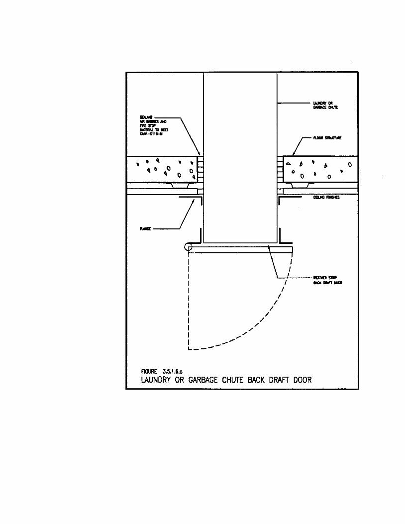
3.5.1.6. Laundries and Garbage Rooms
Laundries and garbage rooms, whether located below grade or not, are connected to the full height of the building by chutes. The shaft enclosing the chute, as with mechanical and electrical shafts, are pathways for air movement. In new buildings, floor slabs should be constructed tight to chutes and sealed to comply with National and Provincial Building Codes for fire rating and smoke control. Refer to Section 3.3., Sentences 4.8. &; 4.9. In existing buildings, the gap between chutes and floor slabs should be sealed from within the garbage and laundry rooms using materials and methods as in new construction. Back draft door at the base of chute should be
3-28
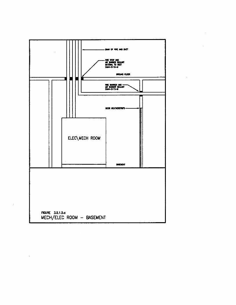
FIGURE 3.5.1.5..
111111 __ ....... "'"
1
/ 1"-" ---.'IEM. 'lU" !illM-SI,W _ .....
ELEC\t.4ECH ROOM
.. _ ... ~ ---C'MI-S11H
.... ----1rI
-
t.1ECH/ELEC ROOt.1 - BASEt.1ENT
, • ~ , , f-,0 f-, Q 0
0 'f-
1
/
" / /
~---
_ ....... ..,,"
flGURE 3.5.1.6.0
,
1----..._00 _ CIIII[
r'--- ... b
, : 0
b , - 0 Q
0
'- J "1
1 _ .......
L \ ,1 \....4-__ ...........
1 _-. ..... 1
1 1
1 1
LAUNDRY OR GARBAGE CHUTE BACK DRAFT DOOR
0
specified with integral seals or should be weather stripped. Damage to seals can occur with everyday use. Replacement of the door seal should be part of routine maintenance. Refer to Section 3.3., Sentence 3.0. Also weatherstrip and seal frames of ail access doors ~_ .. - _ ....... "S.ftI'â PI'V"I,,.,,,,,,iC! 'Data .... n <:Ol'"tinn "!l ":t ~ • .:an~c. ~ n :!Inti 4 n l'iD ... ",'""" &"& ..,1IiiI6 ...... ....,.., .... ..,. ... _ ............... ....-..... a ..... a. _._-, _ ...... _ ... _- _.- ---- ---- -.0
3.5.1.6.a.
3.5.1.7. Corridors. Vestibules and EJevator Lobbies
Corridors, vestibules and lobbies leading to the elevators must be weil sealed to decouple the elevator shafts from the balance of each floor area. Elevators are typically enclosed in the largest shafts of the building. Air is drawn by stack eEfect up these spaces and is pushed by the action of the elevators. Check that lobby and vestibule walls are constructed as air barriers. Weatherstrip lobby door, vestibule door and access doors to the corridor leading from underground parking and fire exit stairs. Seal junctions of frames and walls, seal tops and bases of walls using two part urethane [oam and/or caulking. See Section 3.3, Sentences 4.8 &: 4.9.
3.5.1.8. Pipe Duct and Conduit Penetrations
Continuous lloor slabs and weil sealed walls act effectively to compartmentalize the air at each leve!. A pipe or duct penetration through the completed wall or lloor can leave holes for air movement even when adequately fire stopped with minerai fibre.
In new construction, service chases and sleeves should be fabricated as tightly as possible around pipes and ducts. Pack joints with nonshrink grout and seal gaps. Refer to Section 3.3, Sentences 4.8 &: 4.9. Where existing services are to be sealed, ensure that adequate structural support is provided for the fill material and seal the junction as with new construction. Ensure that fill materials meet or exceed the requirements for fire resistance rating of the assembly.
3.5.1.9. Service and Inspection Hatches
Access hatches such as plumbing clean-outs, electrical panels, mechanical inspection, garbage or laundry chutes and smoke hatches located in ceilings or walls designed to compartmentalize areas must be weatherstripped to ensure a tight fit. Similarly, service hatches in duct work are to have durable and effective gasketing. Large service doors must be weather stripped. Refer ta Section 3.3, Sentence 3.0.
3-29
3.5.1.10. Loadinl Bay
Provide weatherstripping and caulk frames around OtH doors. Compartmentalize the loading bay by weatherstripping access and anciIJary doors. Seal around duct and pipe penetrations in walls, ceilings and floors. Refer to Section 3.3, Sentence 3.11.
3.5.2. Exterior Walls
The exterior walls and roof of a building above grade are commonly understood to incorporate the primary air barrier system of the building. Though these assemblies are generaIJy weIJ understood by Designers and Constructors, junctions of dissimilar materials in new construction and restoring or providing air barrier systems in older buildings remains a problem.
3.5.2.1. The Primaty Air Barrier
ln new construction, there are a wide variety of materials and systems available for cladding, insulating and supporting the building envelope. The air barrier system can be located within the assembly - "Inaccessible system" - or it can be the inside surface of the wall, - "Accessible System", or it can be located at the outside face of the wall - "Face Sealed System". As a "system" it simply requires adequate caulking at all junctions of the various components making up the exterior cladding of the building envelope. This system may he subject to accelerated deterioration through exposure to the Canadian climate. Frequent maintenance and inconvenient access renders this type of system undesirable in high rise commercial buildings.
In the Inaccessible System, air barrier materials are protected within the assembly but must he specified to perform for the life of the building. Accessible system materials are subject to damage by the occupants of the building but they are more easily inspected and maintained.
Criteria for successful installation of Inaccessible and Accessible Systems are elaborated further in the following sections:
3.5.2.2. Iunctions in the Building Envelope
.1 Carrying the air barrier across the junctions hetween various elements of the envelope is of critical importance. Seven
3-30

common locations are reviewed:
o Roof to Wall o Floor to Wall o Wall to Window o Wall to Soffit o Wall to Foundation o Junctions of Dissimilar Materials o Compartmentalization of Cavities
The four characteristic properties of the air barrier must be designed into the junction: air impermeabillty, continuity, structural strength and durability. In addition to continuity of the air barrier itself, continuous support against wind loads must be provided. Also, as these criticallocations are often the site of differential movements, care must be taken to ensure that the air barrier is flexible at the joints. As a general principle, any movement joints or clearance in the building structure must have a flexible air barrier membrane bridging the gap. Care should be taken to ensure that expected deflections in the structure will not exœed the elasticity of the membrane. lt may be necessary in sorne cases to leave slad in the membrane to accommodate movement while adhering it tightly to each side of the joint .
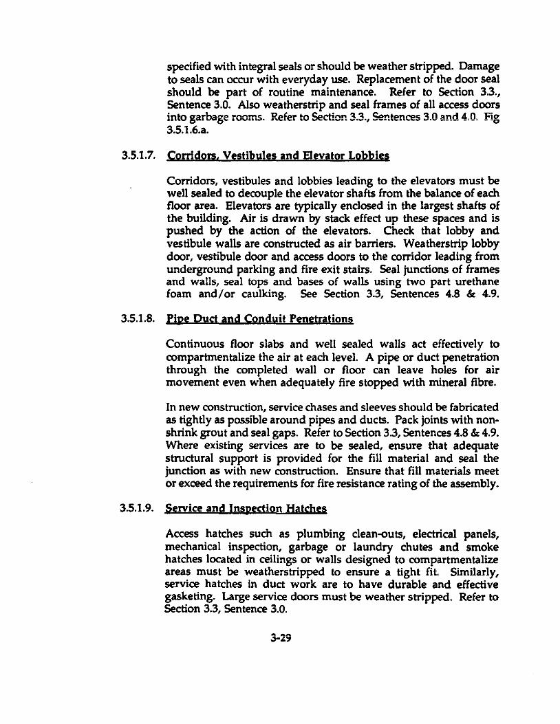
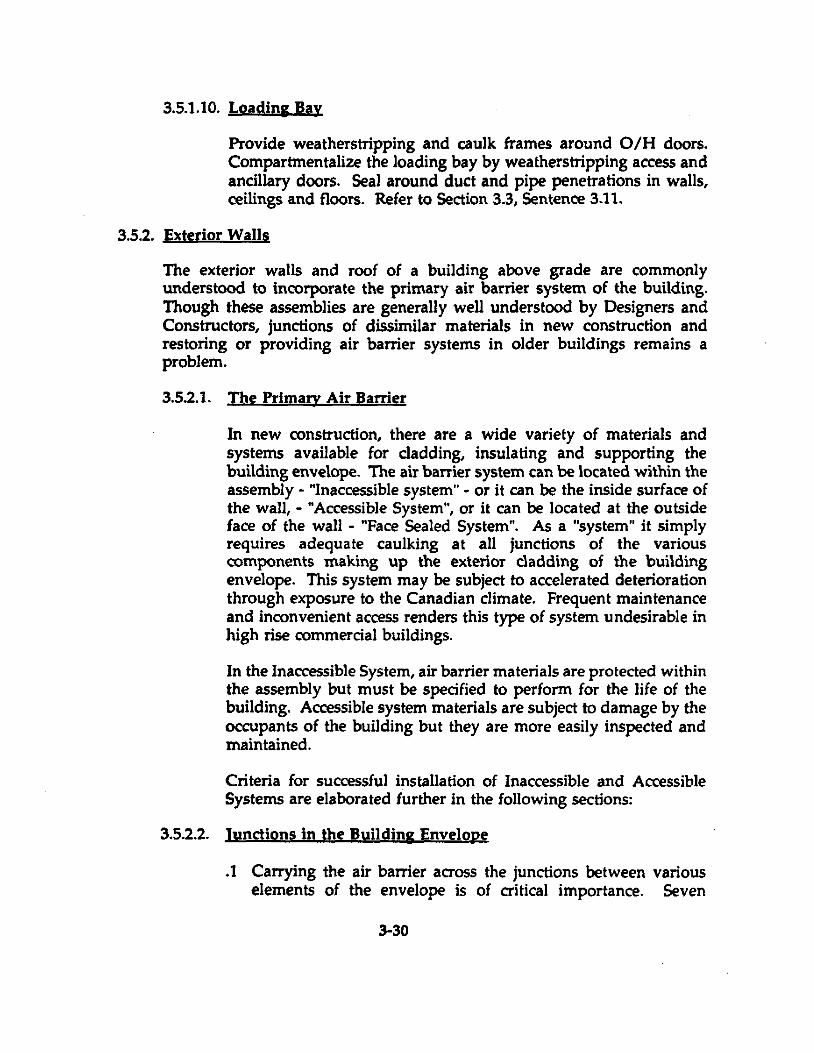
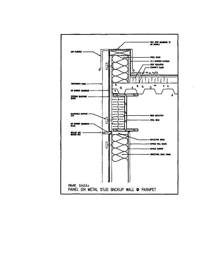
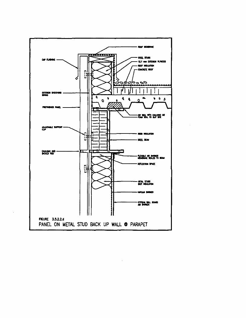
. 2 Exterior Wall to Roof
For Face Sealed Systems, a flexible membrane must wrap over the top of the parapet just beneath the flashing or masonry coping and be sealed to the building face and to the roof membrane.
For Inaccessible Systems, lap and seal together roof and wall membranes. Ensure that materials used are compatible. See Figs. 3.5.2.2.a &: b. In concrete structures, it is possible to maintain continuity of the air barrier system by sealing each membrane to the outside face of the roof slab.
For Accessible Systems, the gypsum board must be installed tight to the underside of roof deck and be caulked or foamed in place. See Figs. 3.5.2.2.c &: d. Altemately. a strip of flexible membrane adhered to the gypsum board and the underside of a steel or concrete deck will seal the joint.
3-31
-- ---I--++:~I'\
... ------+-++::.---'. FAS1DC 11>
.MlRO.....:
~MaD------+--+~~ -""'" - .. ------l ---
FlGURE 3.5.2.2 .•
4-
,
, 0
/'"----- ....... -,. --
4-,
0 • ... , 0 0 0
~ 4. 0
•
---- lIIIUI:I1OII II'IΠ'<!---------.
-~+!-------ILDQCS
1-------.... -
PRECAST ON MASONRY BACKUP WAlL @ PARAPET
rr===ftl~H-----*----.&7 1ICIIMa"'_ -"~tt-t------ .....
......... -----1-_MIl.
~ClP ...... ·---~ Il ~
~ 0 1 ... 0
~ 0 0 ~
Il 6 1
• \) 0 6 \) ~
- .... ----Il:::rM~ç..= ......... Il
... ,.m -_ ... '----1II1IIC1DI ...,.
1-------.. -,-~*----_ .....
, .. 1------_
FIGURE 3.5.2.2.b
PRECAST ON MASONRY BACKUP WALL 0 PARAPET
.. _--......
-------1
n , , U
• __ --~-011
AGURE 3.5.2.2.0
n , , u
~------___ 1II .-..
.r::3-1--------IJ------som_
>-qr ......... _--1IINrIDI ..... ............ , f--------
}+--------4+----- ......... soœ._
PANEL ON METAL STUD BACKUP WALL 0 PARAPET
~-------
--.----i
r=:::t1t-------_~-------mnEW
H-----.--t----~~-
FIGURE J.5.2.2.d
PANEL ON METAL sruo BACK UP WALL 0 PARAPET

In steel buildings with fireproofing on the steel structure, the fireproofing must be removed before sealing measures are undertaken, and then must be restored. Where the roof slab above metal decking is not filled with concrete, for example, at sorne mechanical penthouse roofs, foam the underside of flues as you would with concrete filled deck. In addition, the hollow upper flues must be pierced and the voids filled with foam, for a depth equal to the thickness of the wall below.
ln any case, ensure that membranes or sealants are selected to allow for movement of the structural components .
. 3 Floor to Exterior Walls
For Face Seal Systems, simply ensure that ail joints in the cladding are caulked with a durable sealant.
Inaccessible Systems, bypass the floor to wall junction with a continuous membrane, again, attention must be given to the movement joints in the structure. Membranes must be elastic enough to accommoda te the anticipated movement and should be left slack at the joint. Figs. 3.5.2.2.e, f, g & h.
For Accessible Systems, the base of gypsum board is set in a continuous bead of caulking to seal it to the concrete floor. At the underside of f1oors, the gypsum board must be sealed to the con crete or metal floor structure. A strip of flexible membrane lapped over the joint and adhered to both drywall and f100r structure is recommended. In both new and existing buildings, the joint may be foamed or caulked, particularly where it is difficult to reach.
Any opening at the joint between corrugated metal deck and support structure in steel frame buildings is to be sealed by application of two part polyurethane foam.
Fire stopping the gap between exterior c1adding and floor slab is most often done with a mineraI fibre material. It is effective in preventing flame spread but mineraI wool materials are permeable to air and smoke. Building code amendments seeking improvement in smoke control now require a smoke sealant in this location. Apply mineraI wool fire stop in the conventional manner. Airlsmoke seal the
3-32
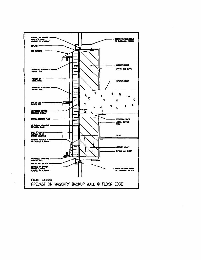
=~--------"'- --------.. _---------... _----;?~~
................. _ ... """"" .. ------t-_ .....
== ".~--......,. __ l'lAIt
.. _-_ ..... LNIIft --_ ....... '" .. _-OII.WGI ........ --.. ..." ..... _ .. -_ ......... ....... "'-FIGURE 3.!i.2.2 ••
4
• 0
" "
-"'---"1+----_ ...... 1--------_IUIIII
• 4 0 Q ... 0 • 0 0
6 Q 0
, 0 • 4
DINI:1DI SM:[ =----iiiiniiii iiiiü. iUiii
_OIDDOIFMIE .. _-PRECAST ON MASONRY BACKUP WALL @ FLOOR EDGE
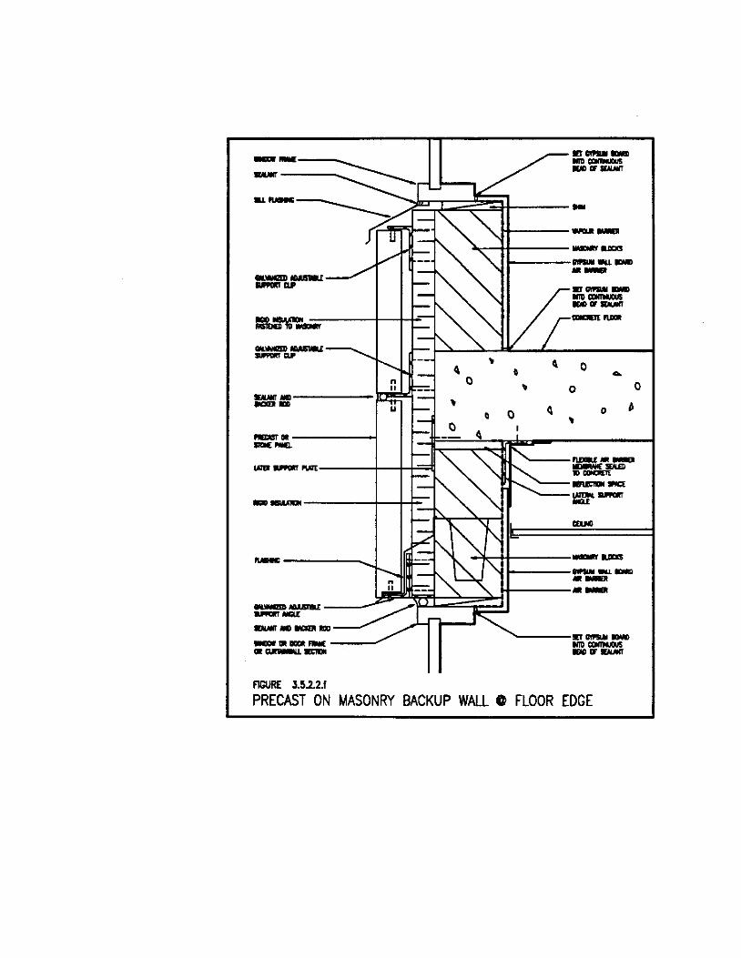
= ----:::::---...-1 1--....
1rI' __ -.... ,......,
__ IIIISM.I
_CU'
---,.-CIL ___ _ CU'
-"" _ ... _00 ---UI1III _ """
--
_ ... _---_/ ... _ ....... AGURE 3.5.2.2.1
n Il
U
" Il
~
, 0
1+-----~-_H_----- .....
~
0
, ~
J----- ..... -
fl , ~
0 ~
.. -1rI' __ -.... ,......, _ .....
0 .... 0 0
0 b ~
fl1lIa!" __ _ ..... 10 """"'" ------... ...... _ ..... ................. .. ---
....... _---.............. .............. .... ,........,
PRECAST ON MASONRY BACKUP WALL @ FLOOREDGE
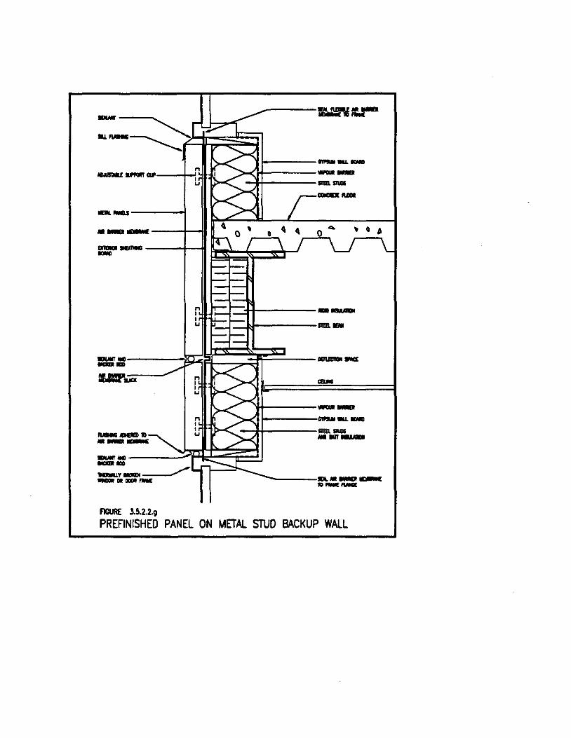
...... ---.....
..........:_ ... --+-1
.... -..-----t - - ----1--11
FIGURE 3.5.2.2.9
~------:u.mv=:-a
1-------><'11+------ -
-llt-----IIIII. ..... --....
, • b
C:3-I--------_.»------II1II. ...
'H-------1-----,-----+l-----iRil. _ . ..,.,-
------lDI. __ _ "_Mm
PREFINISHED PANEL ON METAL STUD BACKUP WALL
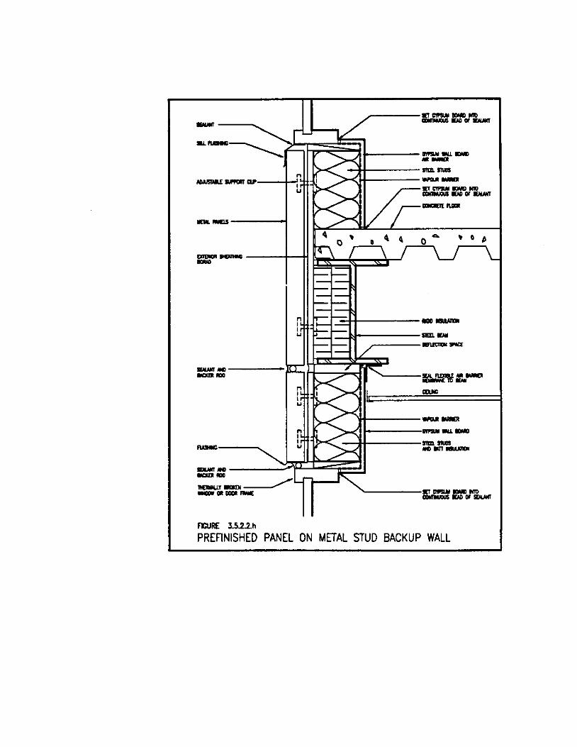
---.........
........... -----~~~~------.....:1+----- sm l1UIII
oWJSIIIU ........... --+-!
..... -.0------1
>-,Hf------ --sn C1PSIM IQMD NID CDHIINUCIUS IDD OF MMT
"""'" IUIIII
... ='" - ---+-H ~~;;;;i=::::~rJ
r:::!~+--------r::::J::I------sm -
r-----I&UC1DI ....
....... "" -----IlJ:: ,+---::;';"'d 1 ....... 1
----........
FlCURE 3.5.2.2.h
'1+------1-----, ....... _-
--+I-----sm l1UIII "" ..........
PREFINISHED PANEL ON METAL STUD BACKUP WALL
joint with a self levelling compound. Refer to Section 3.3, Sentence 4.8. Or seal from below wing foamed cemént mortar. Refer to Section 3.3, Sentence 4.9.
Occasionally a building is constructed with the principal structural columns located outside the floor slab but within the cladding envelope. In these cases, a gap around the column at floor level is found. Seal this gap wing fibre reinforced foamed cement .
. 4 Window to Wall
Standards for air leakage through window glazing and frame assemblies have become more rigid in recent years. Manufacturers perform extensive tests on their products te demonstrate compliance. In non-curtainwall assemblies, this leaves the joint between window frame and rough opening as a weak link in the air barrier system. For Face Sealed Systems, joints between cladding and window frames mwt be caulked with a durable sealant. For Inaccessible Systems, curtainwall technology can be used to make the plane of airtightness continuous. Curtainwall frame sections are designed with pressure plate fittings te restrain the thermal glass units and insulated panels, this same fitting can be used with an appropriately sized spacer to seal a sheet of air barrier membrane te the outside perimeter of the window frame. Once set, this flap is adhered to the air barrier material of the surrounding wall. Some non-curtainwall windows are equipped with an integral membrane attached to the frame and are installed as described above. Consideration must be given te compatibility of the membrane materials, window components and te adhesives.
ln Accessible Systems, the gypsum board membrane must he sealed to the interior of window frames, head, sill and jamb with a continuous bead of durable sealant. Inspection and repair of these joints should be made part of routine maintenance programs.
3-33

Regardless of the location of the air barrier, the void between window frame and masonry or metal stud opening should be filled with a one part polyurethane foam. This will add to the insulation value of the wall and will ensure that thermally broken window frames perform to their optimum value. Figs. 3.5.2.2.e, f, g &t h.
For techniques to seal existing windows and frames, see Section 3.5.3.4 .
. 5 Walls to Soffits
Soffits in new and old building are often a discontinuity in the air barrier system,and so a source of air leakage. Overhangs can be perforated with gaps and hales leading to the building interior without alarming conventional designers, contractors and custodial staff, because they are protected from rain and snow by the building above. The primary air barrier at the vertical faces of the envelope must be continued horizontally at soffit. Figs. 3.5.2.2. i, j, k & 1.
So called, "hot soffits", those containing building services which must not be aIJowed to freeze, must be air sealed at the soffit face. Vertical air barrier materials should extend to the soffit face and be connected to the horizontal system. Ventilation of soffit cavity to the building interior should not be blocked with "hot soffits".
"Cold soffits". those containing no services subject to freezing, offer greater flexibility for air leakage control. Building otherwise c1ad with Face Sea!ed Systems may incorpora te face sealed soffits or may have porous soffits sealed at the underside of the floor slab using inaccessible air barrier methods. If the soffit is face sealed, ensure that ail joints and penetrations are caulked. Recessed light fixture housings and access panels must be sealed as weIJ.
Membranes used in Inaccessible Systems can wrap the structure and be sealed at penetrations.
Accessible Systems rely on the integrity of the con crete floor . slab above the overhang to stop air leakage. Walls below the soffit must be constructed tight to the underside of the f100r above to allow continuity of exterior membrane barriers in
3-34
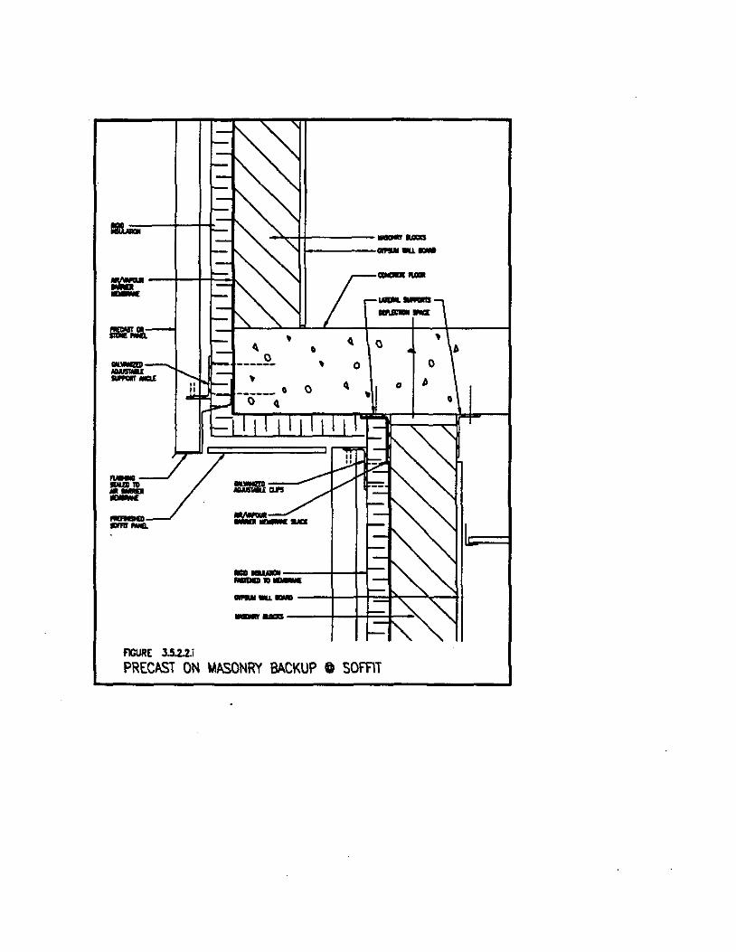
.. -......... .......... -~
FIGURE J.5.2.2.i
~-MIt------ &as
1-----....... --
--_lia ~
~ , Q
~ 0 0 ~
~ ~ Q Il
-_----f--t-......... -
~
•
--- --+---+-+::::I~-T~tI
- .... ----f-+F+-"-
PREC/ISi ON MASONRY BACKUP C SOFFlT
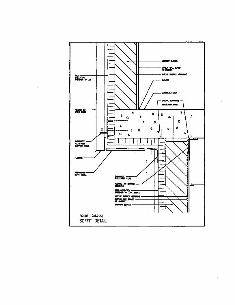
~.Jt
-..... -.
FIGURE 3.5.2.2.j
SOFFIT DETAIL
~
,
-"T-+l------ ......
0
I-----r....:f .'J.If----------
..-.-""""'"' .....
~ ,
0 • ... , 0 0
0 ~ 0 6
•
6
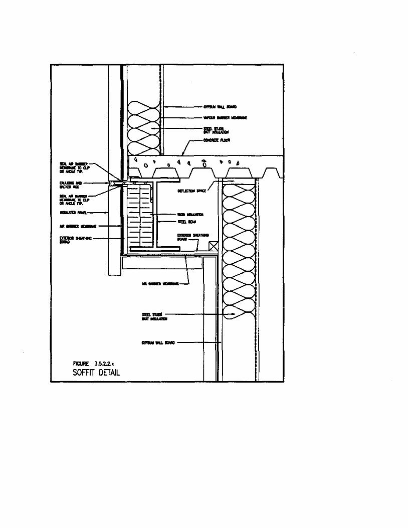
a .. _ -,."" DI MGIr.t: nP.
1-----.... _-
.A-t--------
--·----m~~~~==~ """"'''''' _ ... --,."" CIl Na.( TIP.
--~--I I=+=::::tt----.. ___ -1-.... ~--SlllL'"
=----If-....
FlCURE 3.5.2.2.k
SOFFIT DETAIL
.. _-SIIII. _ ~---+-IhI..-· ~ --.... _ - ----1--111-1
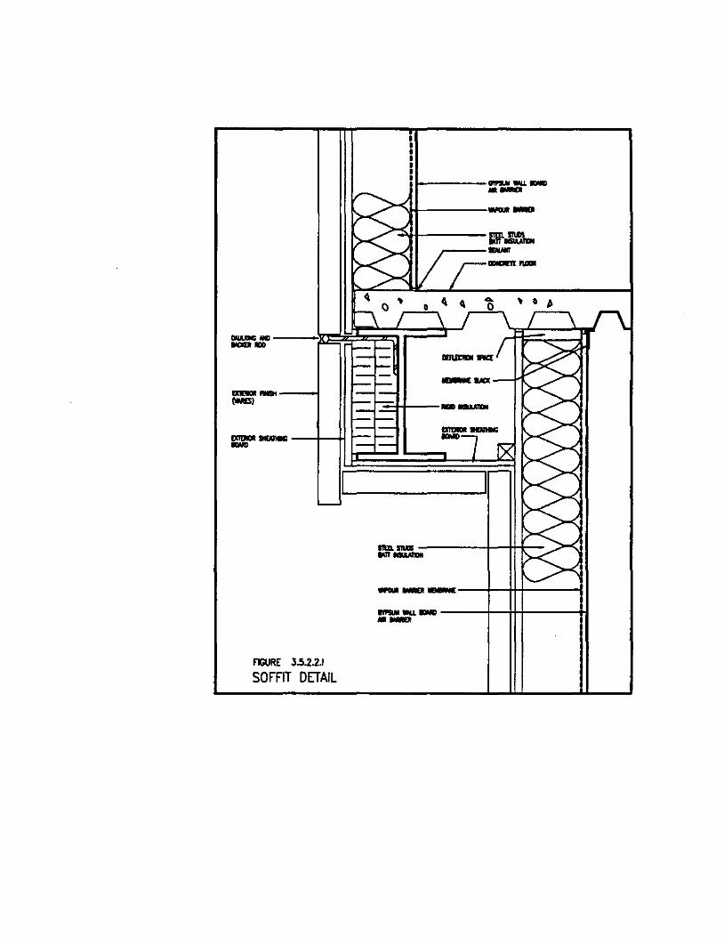
....... _---1 (\MIS)
FIGURE 3.5.2.2.1
SOFFIT DETAIL
i ... -----....... -.. ---""1-------
, 0 f>
_ .... ---1-0["
r.::3-t------
111!1. ..... ------1--4-+4-... -___ --+--iI+-l-----1
........... _ ---4--H-+-----+I .. -

Inaccessible SystemS Of to pfûvide a joint ru he foamed Of
sealed with a membrane in Accessible Systems. .
Penetrations through the envelope for pipes and/or electrical conduit providing power ta light flXtures in the soffit should he sealed with a durable caulking or foam. Figs. 3.5.2.2.m & n.
Close ail other holes leading to sofEits Erom the building. For air leakage control in existing building, access the section of wall which is hetween the sofEit and the floor above. Seal cracks, holes and joints between dissimilar materiais using foam or durable sealants. In some older buildings, this section of wall may have to he reconstructed hefore smaller holes and cracks are sealed .
. 6 Walls al Foundations
Air can leak through the joint between the ground Roor sIab and above grade walls and through the junction of the ground floor slab and top of foundation walls. These joints are caulked in Face Sealed Systems from the exterior with a durable sealant. For Inaccessible Systems, joining the above grade air barrier membrane ta the below grade waterproofing provides a satisfactory sea!. The detaiI should provide for protection of the membranes from frost damage.
Accessible Systems require caulking the base of the wall at the junction with the concrete slab ITom the inside a.."\d caulking or foaming the joint between the floor slab and foundation from inside the basement.
Figs. 3.5.2.2.0, p, q & r .
. 7 Junction between Dissimilar Materials in the Building Envelope
At joints between dissimilar materials in the building face, review the materials or systems ta identify their plane of air tightness and ensure that an air barrier material is used ta connect the planes through the joint. For instance, a sloped. glazed atrium roof incorpora tes a face sealed air barrier. It may abutt a masonry cavity wall incorporating an inaccessible air barrier membrane. The detail must be
3-35

... -----''''''''." _1tIIW. 10 W%T .......,,~
r---,
<1 , , <1 0 ... ~ , 0 0 0 ,
~ , 0 <1 0
0 ,
Q <1
"""\ J 1
;;/" 1
- -""" ..-
FIGURE 3.5.2.2.m
SOFFIT SINGLE PENETRATION DETAIL
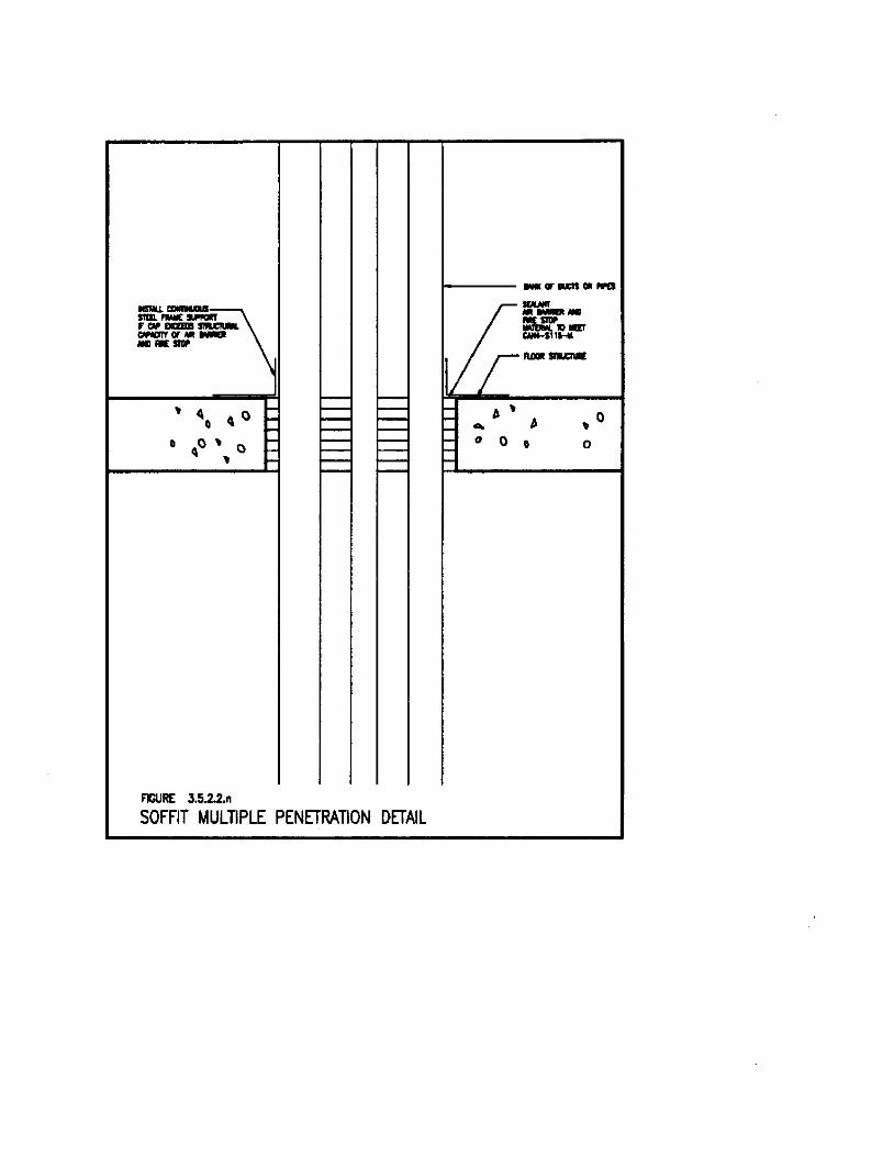
1 1 1 1 1 1
1---- _ or IIICIS Ia_
FIGURE 3.5.2.2.n
SOFFIT MULTIPLE PENETRATION DETAIL
........ ---H~-"""" SIIIlCNE
~ , ... b
" 0 0
, 0
o
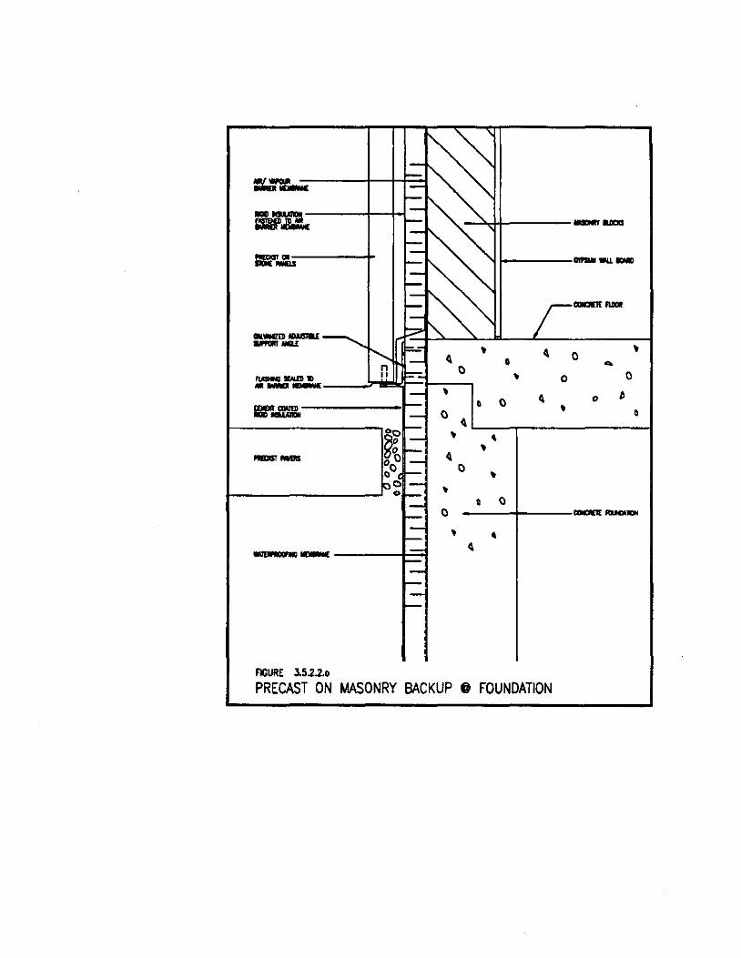
=...w::.-... -=:!Ir.&:..
_ ..... ........ -Mm ...... ........ _ .....
Clll.wm>1OMIIU - ... , 4. • 0 ..
0 , 0 """" ....... 0 --- , () 4. "
~
"""" ...... 0 , ... - () 0 4.
~g , • , _ ......
,,0 4. 00 0 , 0 , 0
0 ()
0 __ lION
, • ~ "UiWIOiC_
FIGURE 3.5.2.2..
PRECAST ON MASONRY BACKUP @ FOUNDATION

""""' .. -----t_ _IMII.
MNC--------~~q caar ...... -------fl --...........
M1ERPRU11'iG -------II--~
F1CURE 3.5.2.2.p
4
~
0
~
~
• 0
•
~~!t_----- ..... 'tt------11---------... _-
=~ _ILOIII
~ , 0
~
0 ... 0 0
~ 0 0 0 ~
• ,
~
0 • 0 0
---+-----, 4
PRECAST ON MASONRY BACKUP @ FOUNDATION
~
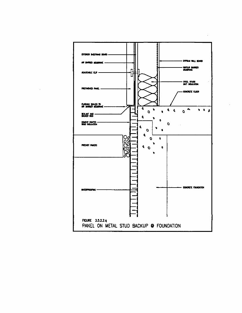
------ -----n -lIWSIOIlE CIJ' , ,
u
som .... IUT.....,... _ ......
.... RlUD1O
j_M» --- ~ / l- , ~ ~
... , 0 ~
1- 0 0 0 == 1- ~ r-I ,
0
"""" "'''''' 1- 0 -- p ~ , 0 • r-' ~
~ l-i 0 0 r-I , -- 1--1
~ r-' ~ 0 0
l- , r-I I-r-I-r-1-r-I I-r-, 1- --wu ......... r-: 1-r-I 1-r-I 1-; r-;
FIGURE 3.!i.2.2.q
PANEL ON METAL STUD BACKUP @ FOUNDATION
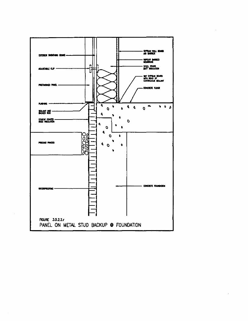
1 III ------+--?t ~ ..... -----H
--------+-
.... ~
== ~
"""" """'" -- '1
CI
-- ~
~------~~
FIGURE 3.5.2.2.r
0
0
111----...... __ --w-----=..,.-it-----STm SIIIIIS
""'-
, 0 ~
, 0
0 • 0
~
"' ....... -...... OF --_ ....
.... , 0 j 0
0 0 , 0 0 ,
-....,r-----
PANEL ON METAL STUD BACKUP 0 FOUNDATION

designed and installed to connect the face seal to the inaccessible air barrier membrane. Figs. 3.5.2.2.s &: t .
. 8 Compartmentalization of Cavities in the Building Envelope
Cavities built into the building envelope, forming part of rain screen assemblies for example, conta in a volume of air which moves around corners and up and down and across the face of buildings by the action of convection and wind. Some movement of air is necessary to vent the cavity but large displacement of air in the cavity will reduce the RSI value in some batt insulations and will increase the migration of air through the wall assembly, particularly at any weak joints.
CMHC has begun testing the benefits of compartmenta1izing the envelope cavities. This study is not final, however a rule of thumb is developing:
o Prevent cavity air from travelling vertically more than 3 storeys.
o Block cavities vertically at al1 corners to prevent movement of air from one building face to the other.
o Install vertical barriers in the cavity approximately 1.2 metres, 3.6 metres and 6 metres from each corner. Provide additional barriers at 6 metre intervals along the building face until you approach another corner. Fig. 3.5.2.8.a.
Two part urethane foam products are recommended ta form the barrier. Ensure that each compartment of the cavity is adequately vented top and bottom and that foam does not black the vents.
3.53. Exterior Wall Qpenin&s
3.5.3.1. plemal DDDrs
In new construction, specify and instal1 door seals to meet or exceed minimum building code standards for air leakage. The following . discussion deals with techniques for air leakage control of existing doors.
3-36
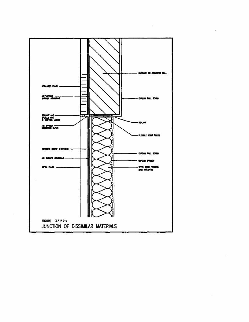
II~I ~,.--~+--- _ .. _-
------1 ="l:..=,=-. ---t:::oH 1------------.~~~~~!=!f~ ...... fIfD ._-.. _---.F _ ....
llIDIJI _ ""'nec ---+-11-
.. - ----1---11
... _----1
FlCURE 3.5.2.2 .•
__ FWfI
1----...... --A+-----__
-Tf-----,SIIII. sn.o_ --
JUNCTION OF DISSIMILAR MATERIALS
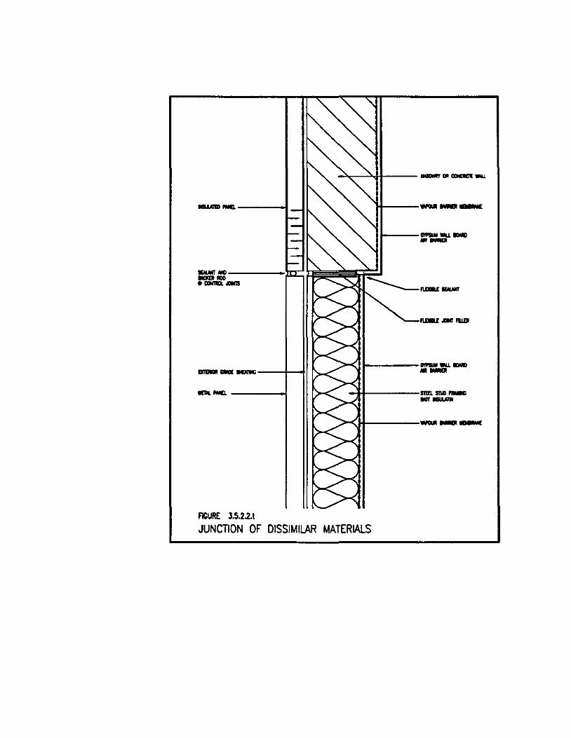
------1 lt-------
......... ----lI:I::: I,-,~~~~ _"'" H ._ .....
IUaI_FIIDI
-----+--11 >0'-111----------------1 -I+-----,SIIIl. .... -.... -
>-<1+--------
FIGURE 3.5.2.2.1
JUNCTION OF DISSIMILAR MATERIALS

PosiIIw pt-.. on wiudwlrd'"
CavIly~ --m~ Badcup .... -
1Of----I.I-." .. , Flgur. 3.5.2.8.1
Corn .. Compertm..,lallDtion
•
·1Irick_ • Cavlly • lnsuIaIion • Memtnna (Ù'tvapour bInIot) • Conc:rete bIocII • GjpSUIII boIId
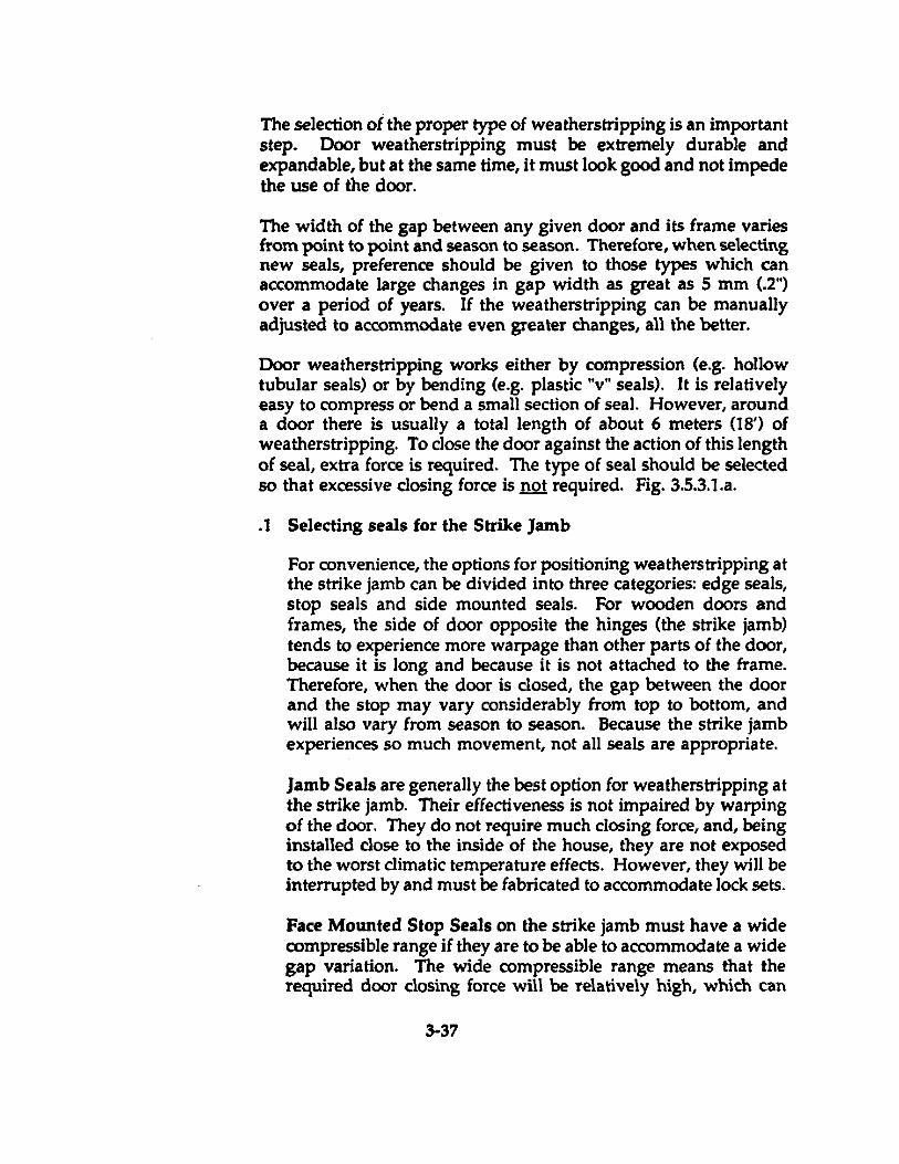
The selection of the proper type of weatherstripping is an important step. Ooor weatherstripping must be extremely durable and expandable, but at the same time, it must look good and not impede the use of the door.
The width of the gap between any given door and its frame varies from point to point and season to season. Therefore, when selecting new seals, preference should be given to those types which can accommoda te large changes in gap width as great as 5 mm (.2") over a period of years. If the weatherstripping can be manually adjusted to accommodate even greater changes, all the better.
Door weatherstripping works either by compression (e.g. hollow tubular seals) or by bending (e.g. plastic "v" seals). It is relatively easy to compress or bend a small section of sea!. However, around a door there is usually a total length of about 6 meters 08') of weatherstripping. To close the door against the action of this length of seal, extra force is required. The type of seal should be selected 50 that excessive c10sing force is 1lQ! required. Fig.3.5.3.1.a .
. 1 Selecting seais for the Strike Jamb
For convenience, the options for positioning weatherstripping at the strike jamb can be divided into three categories: edge seals, stop seals and side mounted seals. For wooden doors and frames, the si de of door opposite the hinges (the strike jamb) tends to experience more warpage than other parts of the door, because it is long and because it is not attached to the frame. Therefore, when the door is closed, the gap between the door and the stop may vary considerably from top to bottom, and will al50 vary from season to sea5On. Because the strike jamb experiences so much movement, not all seals are appropria te.
Jamb Seais are generally the best option for weatherstripping at the strike jamb. Their effectiveness is not impaired by warping of the door. They do not require much c10sing force, and, being installed close to the inside of the house, they are not exposed to the worst climatic temperature effects. However, they will be interrupted by and must be fabricated to accommoda te lock sets.
Face Mounted Stop Seals on the strike jamb must have a wide compressible range if they are to be able to accommoda te a wide gap variation. The wide compressible range means that the required door closing force will be relatively high, which can
3·37
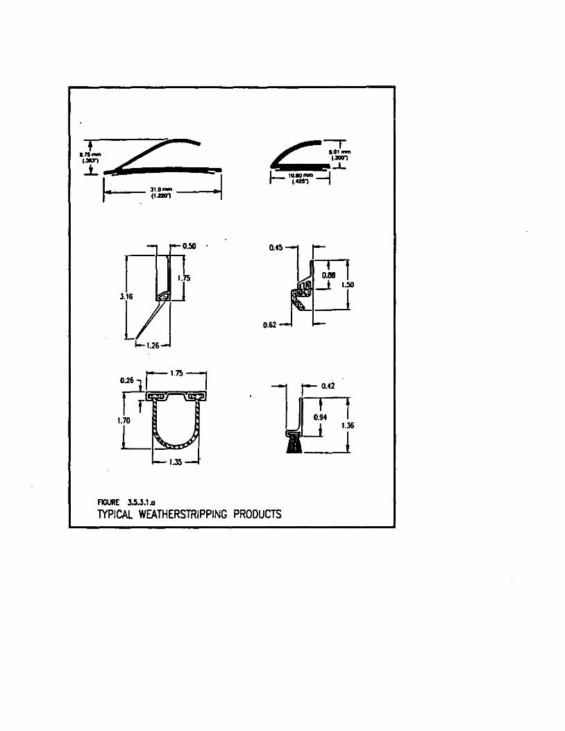
Prr'~Î 1.70
L,~
FIGURE 3.5.3.1.a
C -::r.. ( . ..., -L
L - ........ -----.1 r- (.OWJ 1
TYPICAl WEATHERSTRIPPING PRODUCTS
1
lead to other problems. Stop seals are also more exposed to exterior temperatures, when compared to edge seals, and may not last as long. They are also more susceptible to vandalism.
Side Mounted Stop Seals must also be able to accommodate a wide gap variation. In some designs, this is achieved with spring loading. which allows movement of the seal up to about 6 mm (1/4"). Side mounted seals are also completely exposed to exterior temperatures. Spring loaded seals allow air to pass around the spring when it is compressed.
A combination of Jamb and Stop Seals can be very effective.
Some manufacturers offer special mouldings which give both a jamb and a stop sea!. These are marginally better than jamb seals alone, since they give a good seal around the lock set .
. 2 Selecting Seals for the Head Jamb:
The requirements at the head jamb are the same as for the stoke jamb, though the range of the gap width may be less severe. Where possible, the same seals should be used on the head jamb as on the strike jamb .
. 3 Selecting Seals for the Hinge Jamb:
The door hinges help to resist warping of the door along the hinge edge. As a result, the air gap along this edge is usually small and displays Iimited variation in width. Therefore, the suitability of the different sealing methods changes:
Jamb Seals are a good option because of the relatively narrow and uniform gap along the edge. Self adhesive plastic "v" weatherstrip is a suitable material to use.
Si de Mounted Stop Seals are also a good option provided that the hinges are properly recessed into the jamb .
. 4 Selecting Seals for the SillfThreshold
sm seals can be divided into two main categories: "sweeps" which are attached to the bottom of the door and "threshold seals" which are attached to the door sill.
3-38
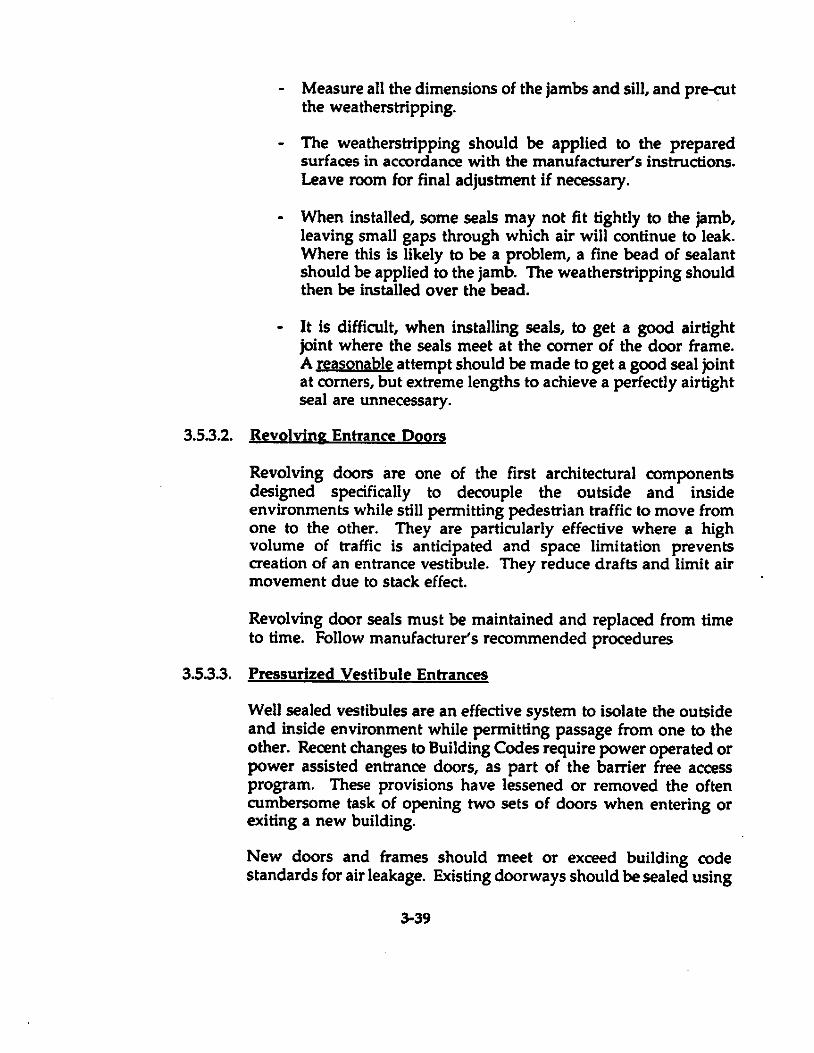
- Measure ail the dimensions of the jambs and sill, and pre-cut the weatherstripping. .
- The weatherstripping should be applied to the prepared surfaces in accordance with the manufacturers instructions. Leave room for final adjustment if necessary.
- When installed, sorne seals may not fit tightly to the jamb, leaving small gaps through whieh air will continue to leak. Where this is Iikely to be a problem, a fine bead of sealant should be applied to the jamb. The weatherstripping should then be installed over the bead.
- It is difficult, when installing seals, to get a good airtight joint where the seals meet at the corner of the door frame. A reasonable attempt should be made to get a good seal joint at corners, but extreme lengths to achieve a perfectly airtight seal are unnecessary.
3.5.3.2. Revolving Entrance Doors
Revolving doors are one of the first architectural components designed specifically to decouple the outside and inside environments while still permitting pedestrian traffic to move from one to the other. They are particularly effective where a high volume of traffie is anticipated and space limitation prevents creation of an entrance vestibule. They reduce drafts and limit air movement due to stack effect.
Revolving door seals must be maintained and replaced from time to time. Follow manufacturers recommended procedures
3.5.3.3. Pressurized Vestibule Entrances
Weil sealed vestibules are an effective system to isolate the outside and inside environment while permitting passage from one to the other. Recent changes to Building Codes require power operated or power assisted entrance doors, as part of the barrier free access program. These provisions have lessened or removed the often cumbersome task of opening two sets of doors when entering or exiting a new building.
New doors and frames should meet or exceed building code standards for air leakage. Existing doorways should be sealed using
3-39
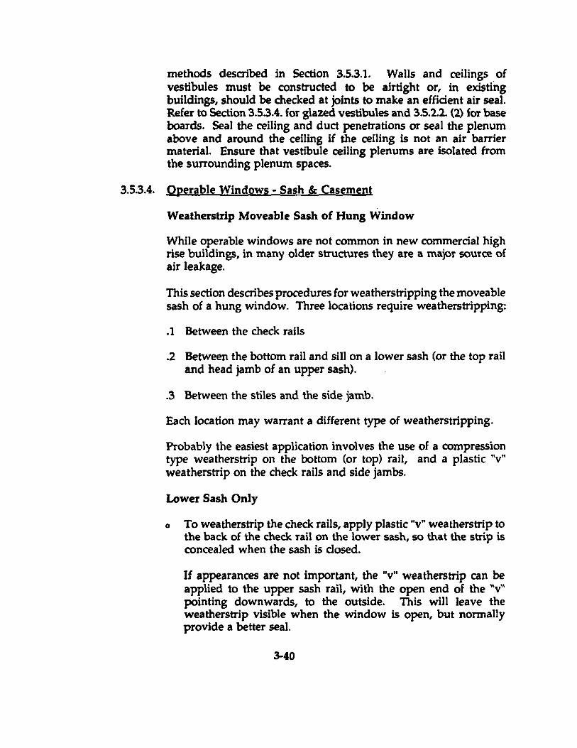
methods described in Section 3.5.3.1. Walls and ceilings of vestibules must be constructed to be airtight or, in existing buildings, should be checked at joints to make an efficient air seal. Refer to Section 3.5.3.4. for glazed vestibules and 3.5.2.2. (2) for base boards. Seal the ceiling and duct penetrations or seal the plenum Aboye and around the ceiling if the ceiling is not an air barrier material. Ensure that vestibule ceiling plenums are isolated from the surrounding plenum spaces.
3.5.3.4. Operable Windows - Sash & Casement
Weatherstrlp Moveable Sash of Hung Window
While operable windows are not common in new commercial high rise buildings, in many older structures they are a major source of air leakage.
This section describes procedures for weatherstripping the moveable sash of a hung window. Three locations require weatherstripping:
.1 Between the check rails
.2 Between the bottom rail and sill on a lower sash (or the top rail and head jamb of an upper sash) .
. 3 Between the stiles and the side jamb.
Each location may warrant a different type of weatherstripping.
Probably the easiest application involves the use of a compression type weatherstrip on the bottom (or top) rail, and a plastic "v" weatherstrip on the check rails and side jambs.
Lower Sash Only
o To weatherstrip the check rails, apply plastic "v" weatherstrip to the back of the check rail on the lower sash, so that the strip is concealed when the sash is closed.
If appearances are not important, the "v" weatherstrip can be applied to the upper sash rail, with the open end of the "v" pointing downwards, ta the outside. This will leave the weatherstrip visible when the window is open, but norrnally provide a better seal.
3-40
o To weatherstrip at the sill, cut compression weatherstrip (e.g., closed cell sponge or hollow core tubular) to the exact width of the sash. Attach securely to the bottom rail of the sash. "V" seals can also be used.
o To weatherstrip the sides of the sash, use self adhesive plastic "v" weatherstrip. Apply it to the side jambs, running up from the slll to the full height of the lower sash. The weatherstrip should be positioned as close to the outside of the house as possible, with the open end of the "v" facing to the outside.
o Check to ensure that the window can still be opened easily. If not, apply a dry lubricant and adjust the stops as required.
o Check to ensure the sash clamp is operable. If not, adjust the clamp, or install a new clamp.
Figs. 3.5.3.4.a, b &: c.
Variations in Technique for Upper Sash Applications
Weatherstripping the YRper sash of hung windows should be handled in the same general way as weatherstripping the lower sash (described above).
Figs. 3.5.3.4.d &: e.
Treat window frames and glazing gaskets as in Section 3.5.3.5.
3.5.3.5. Non-operable Windows
Sealing Window Trim
.1 Run a continuous bead of sealant around the gap between the window trim and wall. Adjust the width of the bead according to the size of the gap. Good caulking technique is required to maintain a tidy bead .
. 2 Run a needle bead into the trim mitre joints, where required. Similarly, run a needle bead into any gap between the trim and the window frame. Remove excess sealant and wipe c1ean .
. 3 Inspect glazing compound, tape or gaskets of window panes. Replace if the material has deteriorated.
3-41

= ..... .
FIgure 3.5.U.I WlI1htlltrfpplng TIlt l.owIr SalI
FIgurt 3.5.3.4.b "V" Weathtrllrlpplng AI Check FlIn
F1gUl't 3.5.Ut COmpression Weatherstrlp Attac:hecl To The Boltom Rail
FJguI'l 3.5.3.4.d w .. \t1IIStrIppIng Upper Sash 01 A Hung WlncloW
Figure 3.5.3.4 .. T W .. 1htrI/I'Ip Attached TO Sldt Jamb
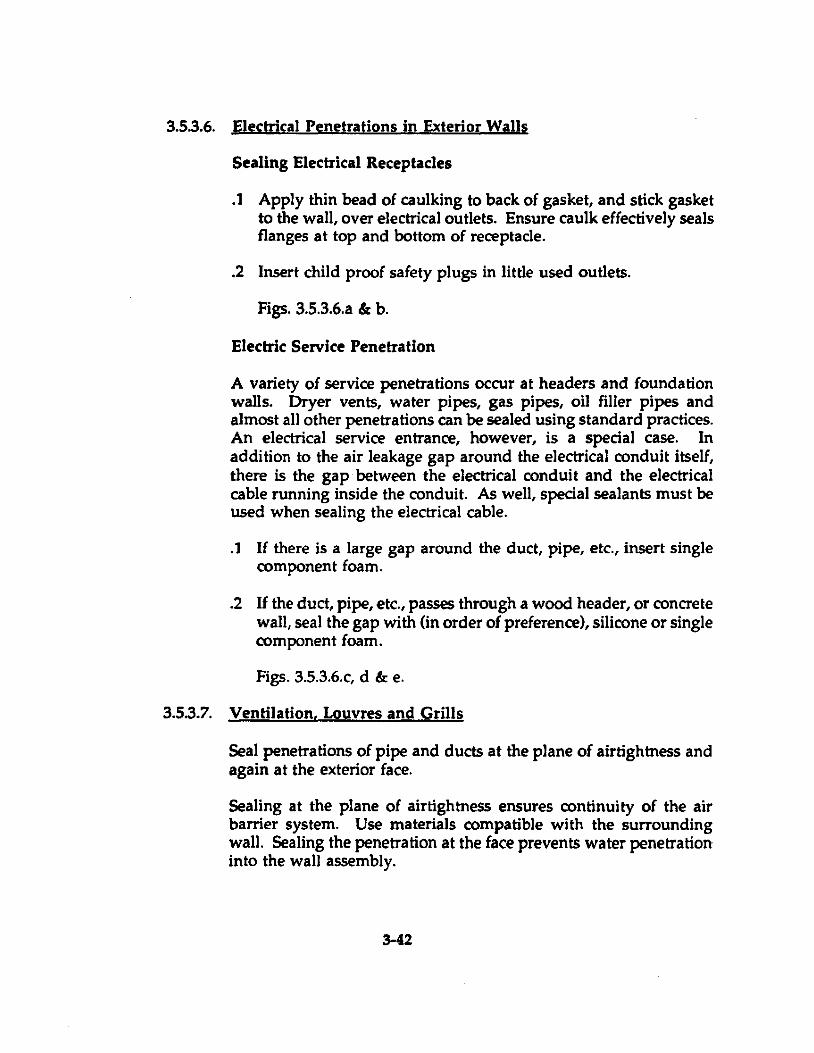
3.5.3.6. Electrical Penetrations in Exterior Walls
Sealing Electrical Receptacles
.1 Apply thin bead 01 caulking to back 01 gasket, and stick gasket to the wall, over eleetrieal outlets. Ensure caulk ellectively seals flanges at top and bottom 01 receptac1e .
. 2 Insert child prool salety plugs in little used outIets.
Figs. 3.5.3.6.a & b.
Electric Service Penetration
A variety of service penetrations occur at headers and foundation walls. Dryer vents, water pipes, gas pipes, oil flUer pipes and almost all other penetrations can be sealed using standard practices. An electrical service entrance, however, is a special case. In addition to the air leakage gap around the electrical conduit itself, there is the gap between the electrical conduit and the electrical cable running inside the conduit. As well, special sealants must be used when sealing the eleetrical cable .
. 1 If there is a large gap around the duet, pipe, etc., insert single component foam .
. 2 If the duct, pipe, etc., passes through a wood header, or concrete wall, seal the gap with (in order of preference), silicone or single component foam.
Figs. 3.5.3.6.e, d & e.
3.5.3.7. Ventilation. Louvres and Grills
Seal penetrations of pipe and ducts at the plane of airtightness and again at the exterior face.
SeaIing at the plane of airtightness ensures continuity of the air barrier system. Use materials compatible with the surrounding wall. Sealing the penetration at the face prevents water penetration into the wall assembly.
3-42
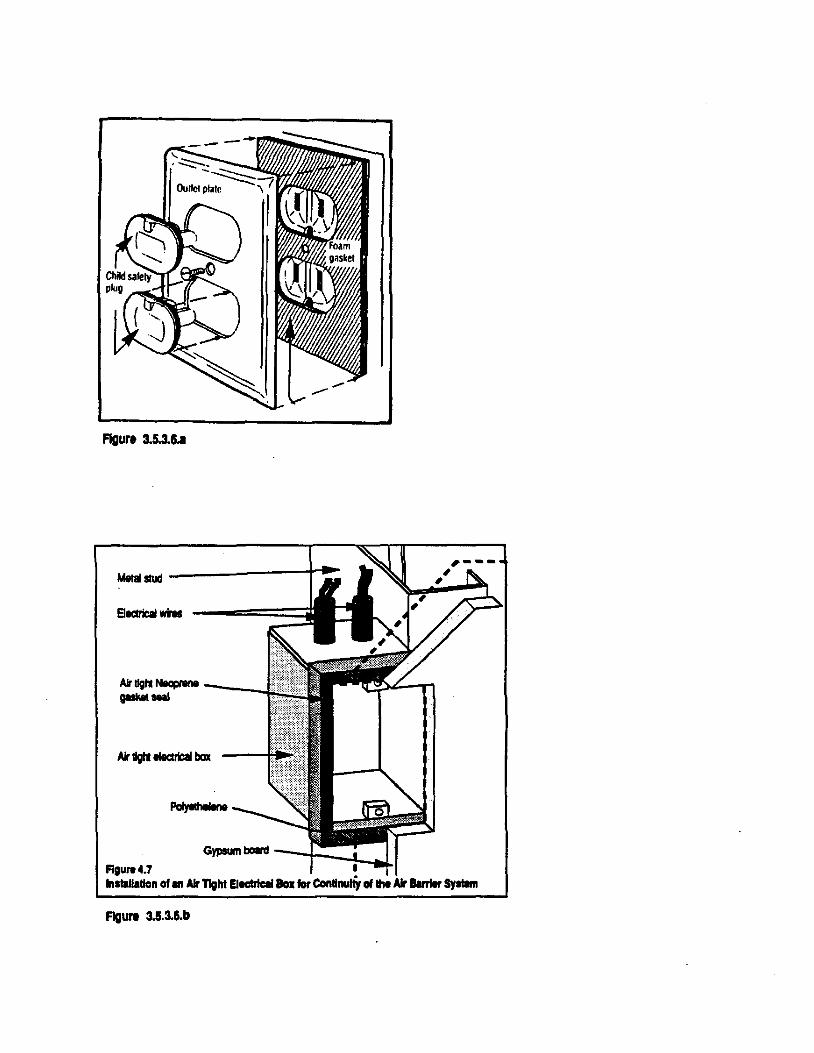
FIgure 3.5.3.6.1
MM.~ --------------~~
Alrllghl ~ __ _
QMMIseaI
Gypsum bOIrd -J--~_J.. FIgure 4.7 installation of an AIr T1ght ElectrlclllIoI: lat CondnulÏy oIl1M AIr Ibm_ Sylllm
figure 3.5.3.5.b
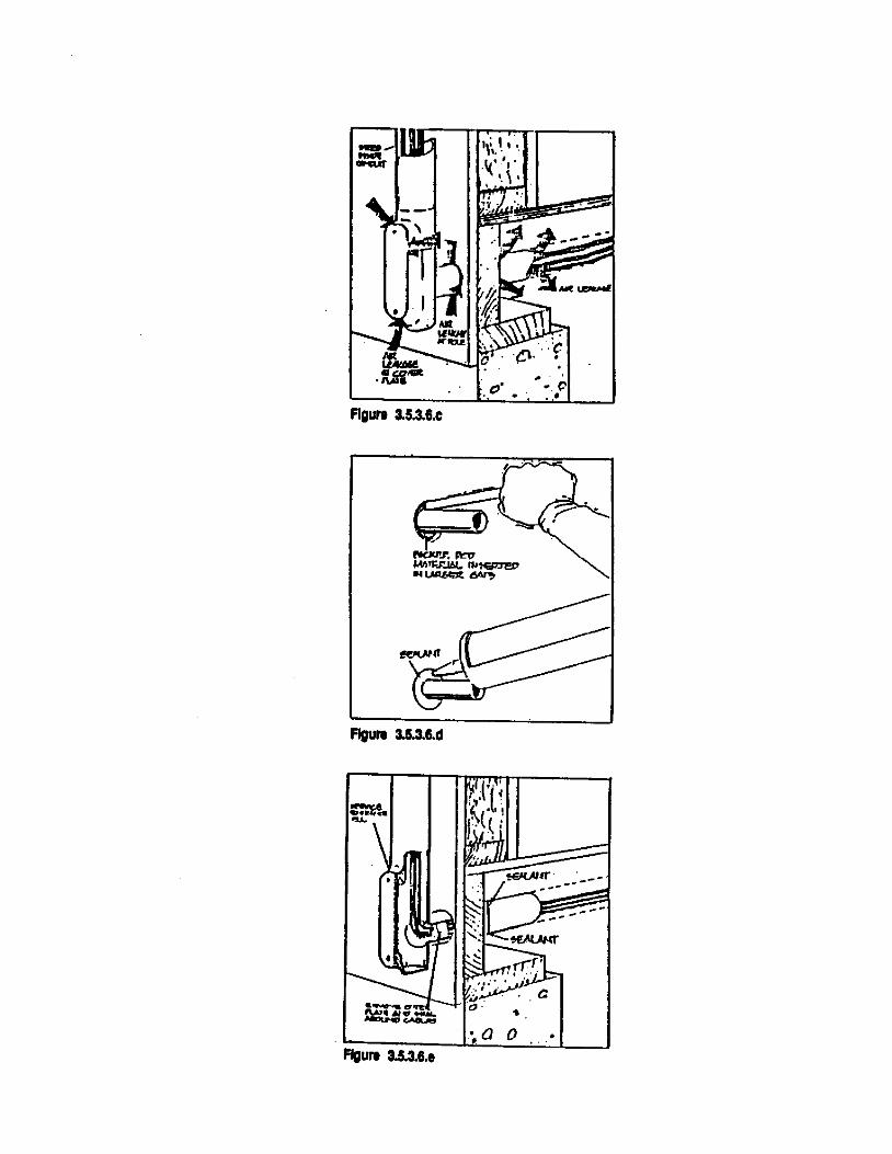
. c'
Figure 3.5.3.6.c
figure 3.5.3.&.d
~Q 0 . figure 3.5.3.6 .•
,. .. c .. '
. "'"""
.--
3.5.3.8. Incrementai ThlOu'" the Wall Units
In some cases, through wall heat pump type units are installed in exterior walls to control local air conditioning needs. The units themselves are not often a sourœ of air leakage, however, the surrounding framed openings are. Caulk or foam the frames to create an effective air seai.
3.5.4. Interior Wall and Openings
3.5.4.1. Partitions to Exterior Wall Iunctions
The hollow cavity of partitions can be a pathway for air infiltration from the exterior unless the partition is adequately separated from the exterior wall at the junction. This is particularly important with Accessible Air Barrier Systems. See Fig. 3.5.4.1.a. In new construction, run the exterior wall gypsum board membrane continuously through the intersection with interior partitions. Seal top and bottom prior to butting the interior partition to the gypsum board and finish conventionally. In existing buildings drill the interior partition adjacent to the outside wall and foam the cavity with two part polyurethane. Extend this treatment above œiling level to the underside of the floor slab above if the partition also projects above the ceiling.
3.5.4.2 Fire Rated DooIS and Partitions
Fire rated doors are located in fire rated partitions. Together these separations are intended to compartmentalize floor areas to reduœ the spread of flame. If properly constructed and maintained, they can also black aiT movement between floor areas and, in the case of stairwells, they can black air flow between floors. Pending provisions to the National and Provincial Building Codes require greater smoke control. At fire separations in new buildings, control of air movement effectively con trois the propagation of smoke.
Fire stop and air seal top of rated partitions at underside of structure using œmentitious foam fire rated to match the wall assembly.
Caulk base of walls.
Weatherstrip doors and caulk junction of walls and door frames. Refer to Section 3.3.
3-43

- ""-----lJa::: ........ ---.----1 (\MD)
"""'" -- ---+--+1 -
-11+-----11BJ. SNI ..... ............. 1-----....... _... -lt-------
...... ...., .....
--;H-----~~noN
1-------.......
_ ... ____ 1P-~:::=i~;!J ........ - ........ FleURE 3.5.4.1.0
WALL JUNCTION - STEEL STUD WALL
......._--
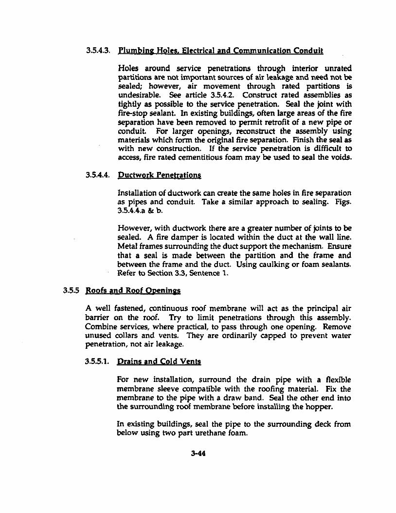
3.5.4.3. Plumbins Holes. Electrical and Communication Conduit
Holes around service penetrations through interior unrated partitions are not important sources of air \eakage and need not he sealed; however, air movement through rated partitions is undesirable. See article 3.5.4.2. Construct rated assemblies as tightly as possible to the service penetration. Seal the joint with fire-stop sealant. In existing buildings, often large areas of the fire separation have been removed to permit retrofit of a new pipe or conduit. For larger openings, reconstruct the assembly using materials which form the original fire separation. Finish the seal as with new construction. If the service penetration is difficult to access, fire rated cementitious foam may be used to seal the voids.
3.5.4.4. puctwork Penetrations
Installation of duetwork can create the same holes in fire separation as pipes and conduit. Take a similar approaeh to sealing. Figs. 3.5.4.4.a & b.
However, with duetwork there are a greater number of joints to be sealed. A fire damper is located within the duet at the wall line. Metal frames surrounding the duet support the mechanism. Ensure that a seal is made between the partition and the frame and hetween the frame and the duet. Using caulking or foam sealants. Refer to Seetion 3.3, Sentence 1.
3.5.5 Roofs and Roof Openings
A weil fastened, continuous roof membrane will act as the principal air barrier on the roof. Try to Iimit penetrations through this assembly. Combine services, where praetical, to pass through one opening. Remove unused collars and vents. They are ordinarily eapped to prevent water penetration, not air leakage.
3.5.5.1. prains and Cold Vents
For new installation, surround the drain pipe with a flexible membrane sleeve compatible with the roofing material. Fix the membrane to the pipe with a draw band. Seal the other end into the surrounding roof membrane before instaUing the hopper.
In existing buildings, seal the pipe to the surrounding deck from helow using two part urethane foam.
3-44
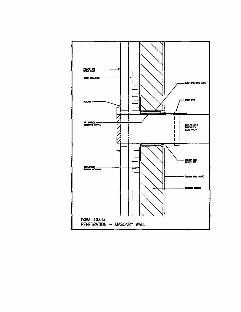
- .. -----1 ---------+--H
----- --
1----_1011 .....
~~I-I----_ .....
FIGURE 3.5.4.4 •• PENETRATION - t.1ASONRY WALL
.....,.----
-------1
FlCURE 3.5.4.4.b
, ... ----...... wou._ -~------
-"~~-------
PENETRATION - MASONRY WALl
3.5.5.2. Çhimneys and Hot Vents
Sea! flange of meta! collar to roof membrane. Sea! meta! collar of hot vents to the vent with high temperature silicone sealant prior to installation or rain deflection flashing.
3.5.5.3. Skylights. Curb Mounted Eguipment and Smoke and Access Hatches
For ail types of curb mounted roof acœssories, ensure that roof membrane rons continuous!y up and over top of curbs. Sea! fixed frames to top of curb by bedding the frame in a continuous bead of caulking. Check weather sea! of operable hatches and replace defective gaskets. Refer to Section 3.3, Sentence 3.8.
At duct penetrations, form a s!eeve around the ductwork using an e!astic membrane material. Seal flange of sleeve to roof membrane at top of curb. Sea! collar of sleeve to duct.
3.5.5.4. Mechanical Pent HOURS
Mechanical penthouses sit on top of service shafts that rise from below grade. They are rooms ordinari!y cooled by ventilation to the exterior through large areas of fixed or operable louvres. They are often uninsulated spaces with cracks between exterior wall materials or are otherwise made of poorly sealed metal or porous masonry. Any hole through the penthouse floor into a shaft below is at the weil head of air ex-filtration in most high rise commercial buildings.
Ideally, the mechanical penthouse would be as tightly constructed as the commercially occupied floors. However, in existing buildings isolating the penthouse from the building at the penthouse floor, may be the only practical solution to controlling air leakage. Seal holes around ducts and pipes through the penthouse floor using methods described in Section 3.3, Sentence 1.8. Cau!king cracks and weatherstripping doors in penthouses otherwise ventilated directly to the outside will have small effect unless the louvre vents are mechanically operated and controlled by thermostat. In that case, every effort should be made to control air leakage through the walls and ceilings of the penthouse using methods described in sections covering Roof Wall Joints, Service Penetrations, Floor Wall Joints and Exterior Doors. In new construction or in comprehensive renovation projects, consider isolating the elevator machine room from the balance of the penthouse, enclose it in an airtight structure
3-45
3.6 Shafts
and air condition the space to cool the equipment. The tops of elevator shafts are difficult to seal because of the moving cables. They are the large shafts in the structure and 50 represent the largest potential fOT aiT movement between floors of the building. Isolating the machine room in this fashion is an effective way to cap the shaft.
JI isolation of the elevator equipment room is not possible, a compromise can be made by reducing air leakage at the top of the shaft.
These are operating elevators and therefore must be shut down before any work is started .
. 1 Clean floor and frame areas around cab les .
. 2 Install good quaUty aluminum duct tape across opening, being sure not to touch cable .
. 3 Apply enough tape to provide soUd seal that will not blow off due to elevator operation .
• 4 Start elevator and observe performance of tape seal.
Once the cable hole is reduced, observe the maintenance and equipment installation hatches. Weatherstrip equipment hatch doors using compression seal such as closed cell foam neoprene.
Replace open grate maintenance hatches with soUd metal ones. Ensure that new hatchways are fitted with air seal gaskets.
lt should be clear from our earlier discussions that air movement between floor leveIs is undesirable. It defeats the efforts of mechanical systems and worse, it is a hazard to the building occupants in case of smoke or fire. Nevertheless, vertical shafts, elevator and stair shafts are a necessary part of high rise commercial buildings. It is important to isolate these vertical spaces as best as possible from each floor level through which they pass.
If the shaft is used exclusively fOT pipes or ducts, the shaft must he sea\ed at each floor using techniques described in Article 3.5.1.8.
3-46
ln new construction, effort should be made to isolate elevator machine rooms from aIl other equipment penthouses. Air-conditioning these spaces rather than cooling with direct to exterior ventilation will save substantial loss of treated air.
ln existing buildings where the elevator penthouse cannot be isolated from other equipment or where cooling of the space is with untreated outside air, the openings between the shaft and penthouse must be sealed or reduced in size to limit air movement. Service hatches should be solid plate steel rather than open grill work. Hatches should be gasketted or weatherstripped.
Elevator cable holes can have their effective open area reduced by application of metal plates and should have a good quality aluminum duct tape applied over the reduced openings to finish the job. Apply enough tape to resist the air pressure created by the operation of the elevations. Ensure that tape does not interfere with the action of the cables.
Fig.3.6.a.
3-47
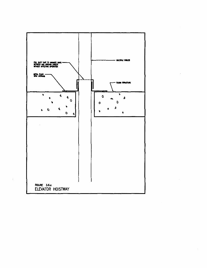
__ AlI. ILe! 111<111 _ .... ~ IDI!DI MC MOUJII CM1S ----. .....
~-----f l \u._
~ ~ ~
0 ~ 0 ~ 0
... ~ 0 0
~ ~ ~
0 () 0
• 0 ~ 0
FIGURE 3.6 .•
ElEVATOR HOISTWAY
Section 4 DESIGN PROCESS AND CONTRACTING PROCEDURES
4.1. Existin; Buildinis
4.1.1. For Desipm:
Determine Air Leakage Paths
Design Repair Solution
Verify Attributes of Air Penneability, Structural Support Requirements for Air Barrier Components.
Require Tests for Acceptable Air Leakage Rates
Identify Locations of Uncontrolled Leakage
Specify Methods and Materials
Require Prequalification of Bidders to Obtain Tenders only from Qualified Air Leakage Retrofit
Review Contractors Work and Test Results
4.1.2. For Contractors:
Obtain Bidder's Package
Check Drawings and Specifications
Check Performance Requirements
Check Test Methods
Check all Penetrations
Prepare Checklist of Points to Seal
Schedule and Execute Work
Restore continuity
Obtain Tests as required.
4-1
4.2 New Construction
4.2.1. For Designers:
Consult Technical Literature and/or Hire Building Envelope Consultant
Consult with Mechanical and Structural Designers to identify Boundaries of Environrnental Zones within the Building and to identify Location of Movement Joints
Choose Air Barrier Friendly Details for Structural Elements within Building Envelope
Designate Values of Performance
Identify an Air Barrier Locations in Drawings with Materials and Method of Installation
Spedfy Sequence of Installation
Use National Master Spedfication 07195
Review Interior Environmental Conditions e.g. Humidity, Temperature
Observe Requirements for Continuity, Structural Support, Ability to Withstand Wind and Fan Pressures and Stack Effect Durability, Acœssibility and Reparability
Test Unproven Designs or Waive Builder's Liability for Performance of Unproven Details
Require Air Barrier Inspections Before Covering the Installation
Commission Building Envelope (This includes Monitoring Performance AEter Repairs, Building Operation Manual for New Air Barrier System, Commissioning Certificate to Owner, Statement of Liability for Future Performance
4.2.2. For Contractors:
Construct for Continui.ty
Check ail Penetrations
4-2

No Substitutions of Materials Without Written Authorization {rom the Consultant
Ensure Understanding and Compliance by a11 Sub-Trades
Inspect and Document Before Covering any Part of an Air Barrier System
4-3
Section 5 CONCLUSIONS, REFERENCES AND RECOMMENDATIONS
5.1. Conclusion
This document has demonstrated that the technologies, materials and methods needed to implement beneficial air leakage control measures in new and existing high-rise commercial buildings have been proven and are readily available. Air leakage control measures reduce energy costs for heating and cooling and offer a speedy retum on investment. Good air barrier design practices give a building greater life expectancy, and retrofit air leakage control measures can stop decay before it gets worse. Proper selection of materials and installation methods can also prevent building problems which may result in reduced safety and eventual liability problems. Controlling air leakage makes it easier to control humidity in the indoor environment, and therefore provide a more comfortable and healthier workplace. Finally, there is an opportunity to prevent the unsightly scarring of 50 many high-rise buildings.
5.2 RecQJDmendations
The potential benefits of air leakage control can only be realized if the measures described are widely implemented. Awareness of the initial design requirements for proper air barrier systems must be increased in the architectural and specification community; knowledge of the materials and methods must be increased among builders and contractors; and developers and other building owners must learn that the economic benefits are worth the investment.
Until recently, there was little recognition of the link between inadequate air barriers and common building problerits. Now that the cause and effects are better known, it would be wise to exploit this opportunity to improve the quality, longevity and economic performance of the entire Canadian high-rise commercial building stock.
5.3 Definitions/Glossary of Terms
For the best available list of definitions, refer to the Air Barrier TEK-AID (1.1.1.).
5.4 National BuildinS Code; Air Barrier 5.3.1.
Oraft Appendix NBC Part 5.
5-1
s.s. Multi-puIpose Air Barrier Materials
Air Barrier plus Vapour Diffusion Retarder Air Barrier plus insulation
5.6. Effeels of Air Leakage Control Measures on Indoor Air Ouality
Since high-rise commercial buildings are designed with ventilation systems to bring in outside air, this is not a signifieant factor.
5.7. Other References and Sources
5.8. Reading Material
"A Study of the Rainscreen Concept Applied to Cladding Systems on Wood Framed Walls." CMHC study by Morrison Hershfield Ltd. Report 3rd August, 1991.
5.9. Appendices
5.10. Disclaimers
5.11. Copyright
5-2