Embed Size (px)
Citation preview

This project is funded by the European Union
And implemented by a consortium led by MWH
Contract №: 2010/232-231
Air Quality Governance in the
ENPI East Countries ‐ AIR‐Q‐
GOV
Development of emission levels associated with the best available techniques and emission limit values for selected sectors and installations
ANNEX IV. Best Available Techniques (BAT) Reference Document for the Non-Ferrous Metal Industries (Copper)
Date: September 11,2013

Development of emission levels associated with the best available techniques and emission limit values for selected sectors and installations
2
Summary
PROJECT TITLE: Air Quality Governance in the ENPI East Countries - AIR-Q-GOV
National Pilot Project - Armenia
Development of emission levels associated with the best available techniques and emission limit values for
ANNEX II.
CONTRACT : 2010/232-231
COUNTRY: Armenia
CONTRACTOR
NAME: CONSECOARD LLC
ADDRESS: Apt.12, Griboyedov str.1a, Yerevan, Armenia
TEL. NUMBER: + 374 91 586635
CONTACT PERSON: Vram Tevosyan
DATE: September 11, 2013
REPORT: Vram Tevosyan
KEY EXPERT: Aiga Kala

Development of emission levels associated with the best available techniques and emission limit values for selected sectors and installations
3
PREFACE
This BAT reference document for the Non-ferrous metals industries (Copper) for Armenian enterprises is elaborated based on the best available techniques (BAT) reference document (BREF) on Non-ferrous metals adopted by the European Commission in 2001 and Draft 3, February 2013 (Joint Research Centre, Institute for Prospective Technological Studies Sustainable Production and Consumption Unit European IPPC Bureau). Chapter 1 of this document provides general information on the industrial sector concerned. Chapter 2 provides information on processes to produce copper from primary and secondary raw materials. Chapters 3 and4 give the consumption data and air emissions for copper production. Chapter 5 presents the BAT conclusions. Description of abatement techniques is presented in Chapter 6. This BREF document covers the techniques for the production of both primary and secondary non-ferrous metals. In addition to basic manufacturing activities, this document covers the associated activities which could have an effect on emissions or pollution. The main operations covered are:
raw materials, storage and preparation; the production processes (pyrometallurgical); emission prevention and reduction techniques.

Development of emission levels associated with the best available techniques and emission limit values for selected sectors and installations
4
CONTENT
1 GENERAL INFORMATION .................................................................................................. 7
1.1 Copper ............................................................................................................................... 7
1.2 Sources of materials and production sites ......................................................................... 7
1.3 Environmental issues ........................................................................................................ 7
1.4 Monitoring ........................................................................................................................ 7
1.4.1 Sampling locations .................................................................................................... 8
1.4.2 Reference conditions ................................................................................................. 8
1.4.3 Continuous and periodic measurement of channeled emissions ............................... 8
2 PROCESSES TO PRODUCE COPPER FROM PRIMARY AND SECONDARY RAW MATERIALS .................................................................................................................................. 9
2.1 Applied Processes and Techniques ................................................................................... 9
2.1.1 Primary copper .......................................................................................................... 9
2.1.2 Secondary copper production .................................................................................. 13
2.1.3 Production of semi-finished products of copper and copper alloys ........................ 15
2.2 Channeled air emissions ................................................................................................. 18
2.2.1 SO2 emissions from off-gases with high SO2 content ( >1% v/v SO2) ................... 19
2.2.2 Applied processes and techniques for off-gases with different SO2 content ........... 19
3 CONSUMPTION DATA ....................................................................................................... 21
3.1 Energy consumption in copper production ..................................................................... 21
3.2 Primary copper input and output..................................................................................... 22
3.3 Secondary copper input and output data ......................................................................... 22
4 EMISSIONS TO AIR ............................................................................................................ 22
4.1 Carbon monoxide ............................................................................................................ 23
4.2 Dust and metal compounds ............................................................................................. 23
4.3 Organic carbon compounds ............................................................................................ 24
4.4 PCDD/F .......................................................................................................................... 25
4.5 Sulphur dioxide ............................................................................................................... 25
4.6 Diffuse emissions ............................................................................................................ 26
4.7 Nitrogen oxides ............................................................................................................... 26
4.8 Summary of air emissions ............................................................................................... 26
5 BAT CONCLUSIONS ........................................................................................................... 27
5.1 Environmental management systems (EMS) .................................................................. 27
5.2 Energy management........................................................................................................ 28

Development of emission levels associated with the best available techniques and emission limit values for selected sectors and installations
5
5.3 Process control and emissions monitoring ...................................................................... 29
5.4 Air emissions .................................................................................................................. 31
5.4.1 Diffuse emissions .................................................................................................... 31
5.4.2 Channeled dust emissions ........................................................................................ 34
5.4.3 Organic compounds emissions ................................................................................ 36
5.4.4 SO2 emissions .......................................................................................................... 37
5.4.5 Reduction of NOx emissions ................................................................................... 40
6 DESCRIPTION OF TECNIQUES ........................................................................................ 40
6.1 Dust emissions ................................................................................................................ 40
6.2 Mist emissions ................................................................................................................ 41
6.3 NOx emissions ................................................................................................................ 41
6.4 SO2 emissions ................................................................................................................. 41
6.5 VOC emissions ............................................................................................................... 42
6.6 PCDD/F emissions .......................................................................................................... 42
7 APPLIED PROCESSES AND TECHNIUQES ..................................................................... 43
7.1 Smelting furnaces............................................................................................................ 43
7.1.1 Reverberatory, hearth or closed-well furnaces ........................................................ 43
7.1.2 Blast furnaces (and the Imperial Smelting Furnace) ............................................... 43
7.1.3 Electric reduction furnaces ...................................................................................... 44
7.1.4 Electric (resistance) furnaces ................................................................................... 45
7.1.5 Ausmelt/ISA Smelt furnaces and the the KRS furnace ........................................... 45
7.1.6 Top blown rotary converter (TBRC) and tilting rotating oxy-fuel furnace (TROF) 46
7.1.7 The Noranda, El Teniente, Baiyin and Vanyukov processes .................................. 46
7.1.8 Mitsubishi process ................................................................................................... 47
7.1.9 QSL furnace ............................................................................................................. 47
7.1.10 Cyclone smelting furnaces ...................................................................................... 47
7.1.11 Outotec flash furnace ............................................................................................... 48
7.1.12 INCO furnace .......................................................................................................... 48
7.1.13 Kivcet (KSS) furnace .............................................................................................. 49
7.2 Converters ....................................................................................................................... 49
7.2.1 The Peirce-Smith Converter .................................................................................... 49
7.2.2 Hoboken converter .................................................................................................. 50
7.2.3 Kennecott/Outotec flash converter .......................................................................... 50

Development of emission levels associated with the best available techniques and emission limit values for selected sectors and installations
6
7.2.4 Other converters ...................................................................................................... 50
LIST OF ABBREVIATIONS
BAT – Best Available Techniques
BREF – BAT Reference document
RA – Republic of Armenia
EC – European Commission
ENP - European Neighborhood Policy
EU – European Union
IPPC – Integrated Pollution Prevention and Control
MNP – Ministry of Nature Protection
KRS – Kayser recycling system
TBRC – Top blown rotary furnaces
FGD – Flue-gas desulphurisation
PCDD/F – Polychlorinated dibenzodioxins and polychlorinated dibenzofurans
VOC – Volatile organic compounds
ESP – Electrostatic precipitator

Development of emission levels associated with the best available techniques and emission limit values for selected sectors and installations
7
1 GENERAL INFORMATION
1.1 Copper
Copper has been used for many centuries; it has a very high thermal and electrical conductivity and is relatively corrosion resistant. Used copper can be recycled without loss of quality. These properties mean that copper is used in diverse sectors such as electrical engineering, automobiles, construction, plumbing, machinery, shipbuilding, aircraft, and precision instruments. Copper is frequently alloyed with Zn, Sn, Ni, Al and other metals to make a range of brasses and bronzes.
1.2 Sources of materials and production sites
Refined copper is produced from primary and secondary raw materials by a relatively small number of copper refineries; their product is copper cathode. This is melted, alloyed and further processed to produce rods, profiles, wires, sheets, strips, tubes, etc. This step may be integrated with the refinery but is frequently carried out at another site.
The only copper producing facility in Armenia is Alaverdy Copper Smelter which produces blister copper mainly from local copper concentrates. There are also several small producers of copper products from local secondary raw materials.
1.3 Environmental issues
Historically the major environmental problem associated with the production of copper from primary sources was the emission of sulphur dioxide to air from the roasting and smelting of sulphide concentrates. This problem has been effectively solved by the EU smelters who now achieve on average 98.9% fixation of the sulphur and produce sulphuric acid and liquid sulphur dioxide.
The main environmental issues associated with the production of secondary copper are also related to the off-gases from the various furnaces in use. There is also the potential for the formation of PCDD/F due to the presence of small amounts of chlorine in the secondary raw materials and the destruction of PCDD/F is an issue that is being pursued.
Diffuse or uncaptured emissions is also an issue that becoming increasingly important for both primary and secondary production. Careful plant design and process operation is needed to capture process gases.
Recycling constitutes an important component of the raw material supplies of the copper refining and manufacturing facilities. Copper can be recovered from the major part of its applications and returned to the production process without loss of quality in recycling.
1.4 Monitoring
This section is intended to ensure that the emissions reported in this document are measured in such a way that the results are representative, mutually comparable and clearly describe the relevant operating state of the plant. The methods and instruments used for sampling and analysis should be the relevant national or international methods. General principles are given below.
The measurement of emissions is used to determine the substances in the clean gas so that they can be reported, used to control the process or abatement plant, or used to predict environmental impacts.
Prior to measurement, plans can be made to take account of:
the mode of operation; the operating state of off-gas purification or effluent treatment plants; operating conditions in the plant (continuous, discontinuous, start-up and shut-down operations, load change); and the effect of thermodynamic interference factors.
Dilution of the gases is not considered acceptable. Factors should be taken into account such as variations of the process, nature and potential hazard of the emissions, and the time needed to obtain a measurable amount of pollutant or representative information. These factors can then form the basis for the selection

Development of emission levels associated with the best available techniques and emission limit values for selected sectors and installations
8
of operating conditions at which the highest emissions may be recorded, the number and duration of the measurements chosen; the most appropriate method of measurement chosen and the position of the measurement locations and points determined. For waste water emissions, qualified random samples can be used or 24 hour composite samples based on flow proportional or time averaged samples can be taken.
For continuous operations, a minimum sample collection time or measurement time of half an hour (half-hourly mean value) is usually necessary. If dust contents are low or if PCDD/PCDF are to be determined, longer measurement times and consequently, other reference times may be necessary because of the limitation of detection. Sampling or measuring should take place only during the operation of the process and dilution air should be excluded. For continuous operation when there are only slight fluctuations in the emission characteristics, three individual measurements can be performed at the highest emission level. If it is anticipated that the emission levels will be very variable during continuous operation, more measurements can be carried out; the sampling and averaging time being limited to the emissions phase.
For batch operation, the measurement time and the averaging time should be modified so that a sample or samples over the whole batch can be taken. These results can be used to calculate averages or to show where peaks occur during the cycle. Again, sampling or measurements should only be made during periods of operation and dilution air should be excluded. 1.4.1 Sampling locations
The sampling points should meet the requirements of the relevant National Guidelines. The sampling points should normally:
be clearly marked, if possible, have a disturbance-free flow in the measurement section, have monitoring points that can be closed, have the required energy supplies, have sufficiently large working platforms, and ensure that the requirements for safety at work are met.
1.4.2 Reference conditions
For emissions to air, the following off-gas parameters should also be determined to convert the emission concentrations obtained to standard conditions of 273 K, 101.3 kPa, measured oxygen content and dry gas:
the volumetric off-gas flow (in order to calculate the concentration and emission mass flow), the off-gas temperature, the water vapour content of the off-gas, the static pressure in the off-gas duct and the atmospheric pressure.
The production rate can also be reported so that the emissions can also be reported as specific emissions per tonne of metal. The specific gas volume Nm3per tonne of metal can also be calculated.
1.4.3 Continuous and periodic measurement of channeled emissions
Continuous monitoring of emissions are measurements with an automated measuring system (AMS)permanently installed on site.
Continuous measurement of several components in gases or in wastewater is possible and in several cases accurate concentrations can be reported continuously or as mean values over agreed time periods (half hourly, daily etc). In these cases an analysis of the averages and the use of percentiles can allow a flexible method of demonstrating compliance with permit conditions and the averages can be easily and automatically assessed.
For emission sources and components that can have a significant environmental impact, continuous monitoring should be specified. Dust can have significant environmental and health effects. In the metals

Development of emission levels associated with the best available techniques and emission limit values for selected sectors and installations
9
sectors, dusts can contain toxic components and the continuous monitoring of dust is important not only for compliance assessment but also to assess whether any failures of the abatement plants have taken place (e.g. bag bursts). To detect bag failures, concentration trends can be analysed or the presence of peak emissions during e.g. reverse jet cleaning of the bags can be observed. Modern dust monitors can interface with the cleaning system to identify which section of the filter contains leaking bags, so that maintenance of the filter can take place.
Even in cases where absolute values may not be agreed as reliable, the use of continuous monitoring can be used to give trends in emissions and as control parameters for the process or abatement plant and are therefore very important.
Periodic measurements are the determination of a measure and at specified time intervals using manual or automated methods. The specified time intervals in general are regular (e.g. once per month or once/twice per year). The sampling duration is defined as the period of time over which the sample is taken. In practice, sometimes the expression 'spot sampling' is used in a similar way as 'periodic measurement'.
2 PROCESSES TO PRODUCE COPPER FROM PRIMARY AND SECONDARY RAW MATERIALS
2.1 Applied Processes and Techniques
2.1.1 Primary copper
Primary copper can be produced by pyrometallurgical or hydrometallurgical processes. Approximately 10 % of the primary copper is produced by the direct leaching of ores (hydrometallurgical route). Nowadays; sulphidic concentrates (15 - 45 % Cu) are the most important raw materials for the pyrometallurgical primary copper route, with a share of more than 85 %. The sulphidic concentrates consist of complex copper/iron sulphides; they are derived from ores that contain 0.5 - 2 % copper by flotation. Further inputs used for primary copper production are fluxes (silicate, lime, sands, etc.), additives/reactants (iron, carbon, etc.) and recycled materials (scrap, dross, lime sludges, used abrasive materials, slags, dusts, etc.). The generic processes are discussed below.
The pyrometallurgical route entails a number of steps, depending on the concentrate used. The majority of concentrates are sulphidic and the stages involved are roasting, smelting, converting, refining and electrorefining. Overviews of smelting furnaces mentioned in this section are given in Annex 1.
2.1.1.1 Concentrate to matte smelting
Concentrates are dried to reduce the moisture content to about 0.2 % prior to the smelting process. For smelting in shaft furnaces, concentrate is dried to 3.5 – 4 % and briquetted.
There are two types of dryers used for drying copper concentrates:
hot gas rotary dryers heated by the off-gases from natural gas combustion, steam heated coil dryers.
The rotary dryer is a rotating drum. The hot gas produced by the combustion of natural gas is placed in contact with the wet concentrate and the contained water is transferred to the gas.
The steam dryers are indirectly heated via steam coils. The throughput depends on the steam pressure; by increasing the pressure to 18-20 bar the capacity can be raised. A small amount of carrier air is introduced to pick up the water of the concentrate.
Roasting and smelting are usually carried out simultaneously in a single furnace at high temperatures to produce a melt that can be separated into a matte (copper sulphide with some iron sulphide) and a slag rich in iron and silica. A fluxing agent that contains silica and, if required, lime (CaO) is usually added to the melt to aid the formation of the slag. The sulphur based gases generated by this process are directed to on-site acid plants to be used as a raw material in the production of sulphuric acid or more rarely, the production of liquid SO2. The smelting stage is then used to separate the copper sulphide from the other solids present in ores by the formation of silicates, particularly iron silicates. This reaction depends on the high affinity of copper to sulphur compared to other metallic impurities.

Development of emission levels associated with the best available techniques and emission limit values for selected sectors and installations
10
In the case of very impure copper concentrates, partial roasting converts the complex sulphides of iron and copper in the concentrate into the simple sulphides, by heating the ore or concentrate under oxidising conditions. The sulphur-based gases generated by this process are directed to an on-site acid plant. The smelting stage is then used to separate the copper sulphide from the other species, such as oxides present in ores, by the formation of silicates, particularly iron silicates.
There are two basic smelting processes in use: bath smelting and flash smelting. The flash smelting process uses oxygen enrichment to produce on autothermal (autogenic) or nearly autothermal operation. Bath smelting processes generally use a lower degree of oxygen enrichment. The use of oxygen also gives higher sulphur dioxide concentrations that make the collection of the gas more effective using one of the sulphur recovery systems (usually the production of sulphuric acid or the production of liquid sulphur dioxide). Table 2-1 shows the smelting processes that are used for primary copper production.
Table 2-1Primary copper smelting technologies Smelting Process Status of Development Remarks
Industrial scale operation
status
Environmentalperformance: potential or constraints
Production level: potential and/or
limitations
Comment
Shaft or blast furnace
Established
Needs to be combined with processes that can recover the heat and sulphur content
Used specifically for low grade concentrates with a low sulphur content and high carbon content
High carbon content makes processing with other technology difficult because of the heat release
Partial roasting and electric furnace smelting
Established
Good
Limitation for production rate
Possible roaster size may be a limiting factor
Outotec flash smelting and Peirce-Smith converting
Established
Good Very high smelting rate possible in one unit, depending on the furnace design and the type of concentrates, 400 000 t/yr blister copper is possible
Worldwide the standard primary copper smelting concept still has potential for improvement
Outotec direct blister flash smelting
Established
Good Three plants in operation, >200 000 t/yr reached
Applicable to concentrates with low iron/low slag fall
Ausmelt/ISA Smelt
Established
Good Upper production rate per unit not tested
Potential for further improvement
INCO flash smelting
Established
Good Limitation of proven smelting rate per unit
Size of furnaces installed. Still further potential
Teniente converter, Noranda process
Established
Good Limitation of smelting rate by reactor size and O2 enrichment limits
Related to other processes relatively higher ingress air ratio requiring increased effort for process gas capture
Development of emission levels associated with the best available techniques and emission limit values for selected sectors and installations
11
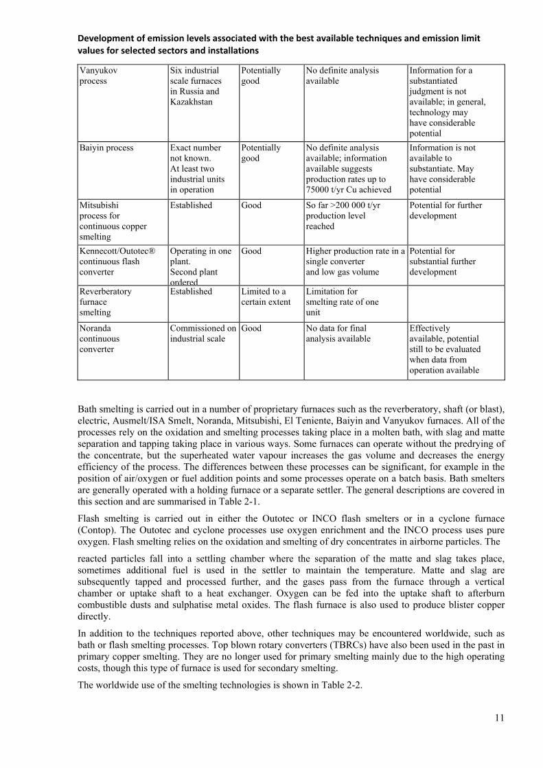
Vanyukov process
Six industrial scale furnaces in Russia and Kazakhstan
Potentially good
No definite analysis available
Information for a substantiated judgment is not available; in general, technology may have considerable potential
Baiyin process
Exact number not known. At least two industrial units in operation
Potentially good
No definite analysis available; information available suggests production rates up to 75000 t/yr Cu achieved
Information is not available to substantiate. May have considerable potential
Mitsubishi process for continuous copper smelting
Established
Good So far >200 000 t/yr production level reached
Potential for further development
Kennecott/Outotec® continuous flash converter
Operating in one plant. Second plant ordered
Good Higher production rate in a single converter and low gas volume
Potential for substantial further development
Reverberatory furnace smelting
Established
Limited to a certain extent
Limitation for smelting rate of one unit
Noranda continuous converter
Commissioned onindustrial scale
Good
No data for final analysis available
Effectively available, potential still to be evaluated when data from operation available
Bath smelting is carried out in a number of proprietary furnaces such as the reverberatory, shaft (or blast), electric, Ausmelt/ISA Smelt, Noranda, Mitsubishi, El Teniente, Baiyin and Vanyukov furnaces. All of the processes rely on the oxidation and smelting processes taking place in a molten bath, with slag and matte separation and tapping taking place in various ways. Some furnaces can operate without the predrying of the concentrate, but the superheated water vapour increases the gas volume and decreases the energy efficiency of the process. The differences between these processes can be significant, for example in the position of air/oxygen or fuel addition points and some processes operate on a batch basis. Bath smelters are generally operated with a holding furnace or a separate settler. The general descriptions are covered in this section and are summarised in Table 2-1.
Flash smelting is carried out in either the Outotec or INCO flash smelters or in a cyclone furnace (Contop). The Outotec and cyclone processes use oxygen enrichment and the INCO process uses pure oxygen. Flash smelting relies on the oxidation and smelting of dry concentrates in airborne particles. The
reacted particles fall into a settling chamber where the separation of the matte and slag takes place, sometimes additional fuel is used in the settler to maintain the temperature. Matte and slag are subsequently tapped and processed further, and the gases pass from the furnace through a vertical chamber or uptake shaft to a heat exchanger. Oxygen can be fed into the uptake shaft to afterburn combustible dusts and sulphatise metal oxides. The flash furnace is also used to produce blister copper directly.
In addition to the techniques reported above, other techniques may be encountered worldwide, such as bath or flash smelting processes. Top blown rotary converters (TBRCs) have also been used in the past in primary copper smelting. They are no longer used for primary smelting mainly due to the high operating costs, though this type of furnace is used for secondary smelting.
The worldwide use of the smelting technologies is shown in Table 2-2.

Development of emission levels associated with the best available techniques and emission limit values for selected sectors and installations
12
Table 2-2: Worldwide use of the smelting technologies
Process Number of smelters Number of furnaces
Blister production
1998 (1000 t/yr)
Outotec flash smelting 26 26 3801 Outotec flash smelting, direct blister 3 3 238 Reverberatory furnace 27 37 1604 El Teniente reactor 7 12 1344 Electric furnace 6 8 560 Blast furnace 14 29 548 Mitsubishi process 4 4 497 INCO flash smelting 3 3 448 Vanyukov process 3 5 448 Ausmelt/ISA Smelt 11 13 1000 Noranda reactor 2 2 197 Bay in process 1 1 57 Kivcet 1 1 15
The reverberatory furnace is used for matte smelting in Armenia. It does not use the energy content of the sulphur and the iron in the concentrate and instead relies on the use of Natural gas to melt the concentrates by the hot combustion gases sweeping over the hearth. Therefore the process is not as efficient as the other processes described. The combustion gases are added to the overall gas volume and this results in a very low sulphur dioxide content, which is very difficult to remove effectively. The use of reverberatory furnaces has declined significantly since the 1970s.
2.1.1.2 Converting
Three types of converter processes are used during primary process, two are matte conversion processes and one is on alloy conversion. The matte conversion processes are the conventional batch processes, which are most commonly used, and the continuous converting process.
Batch matte converting process
The batch converting process comprises two stages. It is carried out by blowing an air/oxygen mixture through the matte recovered from the smelting operation. A cylindrical bath furnace is most commonly used and flux additions are made. In the first stage, iron and part of the sulphur are oxidised and slag and sulphur dioxide gas are formed; the slag is skimmed off periodically and is further processed to recover copper. Normally the first stage blow is carried out in several steps with incremental matte additions. In the second stage, i.e. the copper blow, the copper sulphide is oxidised to blister copper (98.5 % Cu) and more sulphur dioxide gas is formed. The blister copper is tapped at the end of the copper blow. The process is operated to control the residual sulphur and oxygen in the blister copper. The sulphur dioxide that is formed is further treated for sulphur recovery, normally in a sulphuric acid plant.
The reaction is strongly exothermic and also volatilises metallic impurities such as lead and zinc that are then captured in an abatement plant and recovered. The process heat can also be used to melt anode scrap and other copper scrap without the addition of primary heat. There can be variations in sulphur dioxide concentrations during the various stages of conversion, depending on the type of furnace used.
The Peirce-Smith and the Hoboken type converters are operated batch wise, (they are referred to as Peirce-Smith or similar converters in this chapter). They are cylindrical bath furnaces with laterally arranged tuyères for air/oxygen blowing. The Ausmelt/ISA Smelt furnace has also been used for the batch wise conversion of matte into blister copper. Top blown rotary converters (TBRC) have been used inthe past for batch wise conversion of primary copper material to blister copper but are not in use anymore.
Continuous matte converting process
The continuous converting processes that are in industrial use are the Kennecott/Outotec flash converting furnace, the Mitsubishi furnace (which forms part of the integrated Mitsubishi process) and the Noranda converter.
Development of emission levels associated with the best available techniques and emission limit values for selected sectors and installations
13
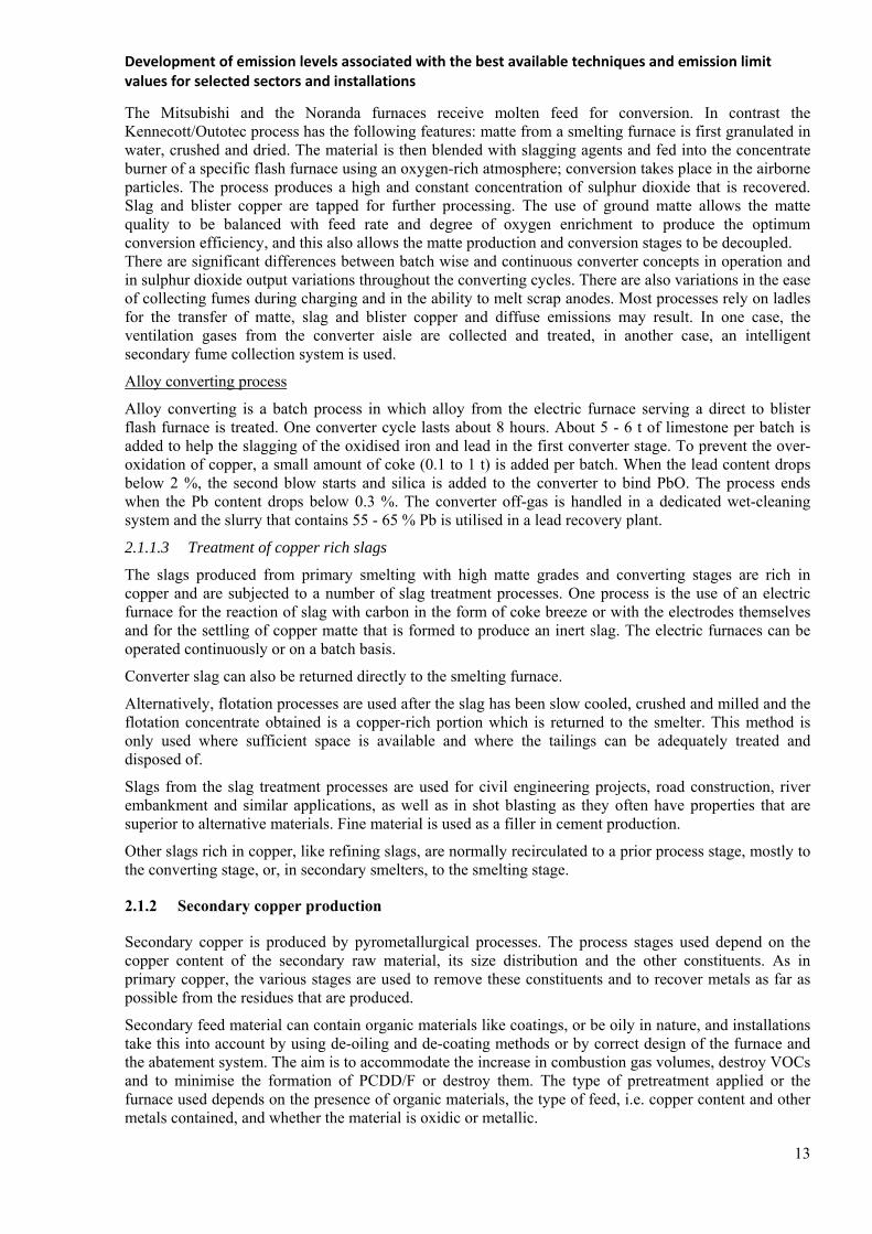
The Mitsubishi and the Noranda furnaces receive molten feed for conversion. In contrast the Kennecott/Outotec process has the following features: matte from a smelting furnace is first granulated in water, crushed and dried. The material is then blended with slagging agents and fed into the concentrate burner of a specific flash furnace using an oxygen-rich atmosphere; conversion takes place in the airborne particles. The process produces a high and constant concentration of sulphur dioxide that is recovered. Slag and blister copper are tapped for further processing. The use of ground matte allows the matte quality to be balanced with feed rate and degree of oxygen enrichment to produce the optimum conversion efficiency, and this also allows the matte production and conversion stages to be decoupled. There are significant differences between batch wise and continuous converter concepts in operation and in sulphur dioxide output variations throughout the converting cycles. There are also variations in the ease of collecting fumes during charging and in the ability to melt scrap anodes. Most processes rely on ladles for the transfer of matte, slag and blister copper and diffuse emissions may result. In one case, the ventilation gases from the converter aisle are collected and treated, in another case, an intelligent secondary fume collection system is used.
Alloy converting process
Alloy converting is a batch process in which alloy from the electric furnace serving a direct to blister flash furnace is treated. One converter cycle lasts about 8 hours. About 5 - 6 t of limestone per batch is added to help the slagging of the oxidised iron and lead in the first converter stage. To prevent the over-oxidation of copper, a small amount of coke (0.1 to 1 t) is added per batch. When the lead content drops below 2 %, the second blow starts and silica is added to the converter to bind PbO. The process ends when the Pb content drops below 0.3 %. The converter off-gas is handled in a dedicated wet-cleaning system and the slurry that contains 55 - 65 % Pb is utilised in a lead recovery plant.
2.1.1.3 Treatment of copper rich slags
The slags produced from primary smelting with high matte grades and converting stages are rich in copper and are subjected to a number of slag treatment processes. One process is the use of an electric furnace for the reaction of slag with carbon in the form of coke breeze or with the electrodes themselves and for the settling of copper matte that is formed to produce an inert slag. The electric furnaces can be operated continuously or on a batch basis.
Converter slag can also be returned directly to the smelting furnace.
Alternatively, flotation processes are used after the slag has been slow cooled, crushed and milled and the flotation concentrate obtained is a copper-rich portion which is returned to the smelter. This method is only used where sufficient space is available and where the tailings can be adequately treated and disposed of.
Slags from the slag treatment processes are used for civil engineering projects, road construction, river embankment and similar applications, as well as in shot blasting as they often have properties that are superior to alternative materials. Fine material is used as a filler in cement production.
Other slags rich in copper, like refining slags, are normally recirculated to a prior process stage, mostly to the converting stage, or, in secondary smelters, to the smelting stage.
2.1.2 Secondary copper production
Secondary copper is produced by pyrometallurgical processes. The process stages used depend on the copper content of the secondary raw material, its size distribution and the other constituents. As in primary copper, the various stages are used to remove these constituents and to recover metals as far as possible from the residues that are produced.
Secondary feed material can contain organic materials like coatings, or be oily in nature, and installations take this into account by using de-oiling and de-coating methods or by correct design of the furnace and the abatement system. The aim is to accommodate the increase in combustion gas volumes, destroy VOCs and to minimise the formation of PCDD/F or destroy them. The type of pretreatment applied or the furnace used depends on the presence of organic materials, the type of feed, i.e. copper content and other metals contained, and whether the material is oxidic or metallic.

Development of emission levels associated with the best available techniques and emission limit values for selected sectors and installations
14
If a furnace such as a converter is used to smelt impure brass scrap to separate the metals contained in it, the alloying elements are fumed from the copper to produce black copper and a zinc-rich filter dust.
A wide range of secondary raw materials are used and some of them are described in Table 2-3. Table 2-3: Secondary raw materials for copper production
Type of material Cu-content (wt-%)
Sources
Mixed copper sludges 1-25 Electroplating Computer scrap 15-20 Electronics industry Copper mono-sludges 2-40 Electroplating Copper-iron material (lumpy or comminuted) from armatures, stators, rotors etc.
10-20 Electrical industry
Brass drosses, copper-containing ashes and slags 10-40 Foundries, semi-finished product plants
Red brass drosses, copper-containing ashes and slags
10 -40 Foundries, semi-finished product plants
Shredder material 30- 80 Shredder plants Copper-brass radiators 60- 65 Cars Mixed red brass scrap 70- 85 Water meters, gear wheels,
valves, taps, machine components, bearing boxes, propellers, fittings
Light copper scrap 88- 92 Copper sheets, eaves, gutters, water boilers, heaters
Heavy copper scrap 90-98 Sheets, copper punchings, slide rails, wires, pipes
Mixed copper scrap 90- 95 Light and heavy copper scrap
Copper granules 90 -98 From cable cominution Pure No. 1 scrap 99 Semi-finished products,
wire, cuttings, strip
The stages used for secondary copper production are generally similar to those for primary production but the raw material is usually oxidic or metallic and process conditions are therefore varied. Smelting of secondary raw materials therefore uses reducing conditions.
2.1.2.1 Secondary copper smelting stage
A number of furnaces such as the blast, Mini Smelter, top blown rotary furnaces (TBRC), sealed submerged arc electric furnace, Ausmelt/ISA Smelt furnace (KRS or Kayser recycling system), reverberatory, and rotary are used for low and medium grade material. Contimelt systems are used for high grade copper scrap (>99 % Cu).
The type of furnace and the process steps used depend on the copper content of the secondary raw material, its size and other constituents. The smelting and refining of secondary copper istherefore complex and the type of secondary material, which can be processed is dependent on the particular facilities and furnaces available.
Iron (in the form of irony copper, normal iron scrap, etc.), carbon (in the form of coke or natural gas) and fluxing agents are added to reduce metal oxides if required and the processes are operated to suit the feed material. Reduction smelting results in the volatilisation of mainly zinc, tin and lead, which are discharged as oxides with the off-gas and are collected in the dust collection system. The content of dust, sulphur dioxide, PCDD/F and VOCs in the fume from the furnaces depend on the raw materials. For a further clean-up after dust separation, the off gas can be routed to a contact process sulphuric acid

Development of emission levels associated with the best available techniques and emission limit values for selected sectors and installations
15
production unit after additional wet scrubbing. The collected flue-dust is sent to further processing to recover the metals separated from the input materials.
The Mini-Smelter is also used for secondary copper production, using scrap that contains iron and tin. In this application, the iron acts as the reducing agent in the first stage to produce metallic copper and then oxygen is blown into the melt to oxidise iron and the other metals (lead and tin) present which are recovered in the slag. The oxidation of the iron content provides the heat to drive the process and excess heat is recovered.
The KRS process uses the Ausmelt/ISA Smelt furnace. The combination is an advanced technology which replaces the conventional blast furnace/converter technology in non-ferrous metals recovery from secondary raw materials. Typical input materials include copper and precious metal-bearing secondary raw materials from copper smelting and refining, copper casting plants, the metal processing industry or from recycling plants for copper-bearing materials such as electric and electronic scrap, copper alloy scrap, copper-rich slags, copper dross, filter and cyclone dust, precipitation sludges and wire-drawing sludge.
In principle, electric furnaces process the same materials as the KRS or the blast furnace. The electric furnace requires a lower material input per tonne of black copper output than the blast furnace which, unlike electric furnaces, cannot normally be operated without return slag.
2.1.2.2 Converting, fire-refining, slag treatment and the electrorefining, processing of pure alloy scrap
The converting and refining furnaces used are the same as those used for primary production, and the slag treatment systems and electrorefining processes are also the same. The main difference is that converters used for secondary production treat metal and not matte. They use coke as fuel for melting and, to make up for process heat deficits in the primary converters, the matte provides the necessary process heat. Secondary converters also oxidise and slag minor elements like iron, and separate other metals like zinc or tin by volatilisation. They produce a converter copper in a quality that suits fire-refining. The heat of the reaction when air is blown into the converter is used to volatilise metallic components; slagging agents are used to remove iron and some lead. Fire refining furnaces are also used to melt higher grade scrap. There are potential sources of diffuse emissions from secondary converters.
The electrorefining slimes and spent solutions are also sources of precious metals and other metals such as nickel. These are recovered in the same manner as those from primary production.
Copper alloys such as bronzes and brasses are also used as secondary raw materials in a number of processes. If impure or mixed with other alloys, they are processed in the secondary smelting and refining circuits.
The pure alloy is used directly for semis fabrication. Induction furnaces are used to melt the clean material followed by casting into shapes suited for the further fabrication step. Charge analysis and control is practised to produce the desired alloy without the major additions of virgin metal. Zinc oxide can be collected from the filter dust.
Depending on the type of feed materials in some plants, a flue-dust is produced in the first stage that is rich in zinc and lead, for example during the blast furnace smelting of lower grade material. These dusts contain up to 65 % combined zinc and lead and are a feed material for highly suitable processing in lead production processes for the production of lead and zinc.
2.1.3 Production of semi-finished products of copper and copper alloys
Copper and copper alloys are melted continuously or in batches and cast for the production of shapes suited to the further fabrication step. The cast products are precursors for a variety of materials such as sheets, strips, sections, bars, rods, wires and tubes. Generally the following routes are taken:
billets are mostly made from copper and copper alloys for the production of tubes or sections and rods;
slabs and cakes are cast from copper and copper alloys for the production of sheets or strips; special processes are applied for specific products from copper and copper alloys: the
Up cast process for wires and tubes,

Development of emission levels associated with the best available techniques and emission limit values for selected sectors and installations
16
horizontal continuous casting for strip and sections, vertical strip casting and roll processes for the fabrication of copper tubes.
2.1.3.1 Melting processes
Copper or copper alloys can be melted in batches in an electric or induction furnace (crucible or channel type). When high melting rates are required, copper is also melted continuously in ashaft furnace. Crucible or reverberatory furnaces are also used for melting and fire-refining copper. The fume collection and abatement systems are chosen according to the raw material and the degree of contamination present. The gas collected from electric furnaces is normally cleaned in cyclones followed by fabric filters. For gas-fired shaft furnaces, the control of the burners is a critical factor to minimise the CO content of the gases emitted. An afterburner followed by heat recovery systems are in use if the CO content is high enough (e.g. > 5 % CO); fabric filters are also used for dedusting in shaft furnaces.
Copper cathode and copper and alloy scrap is used as the raw material and is normally stored in open bays so that the different alloys can be blended to produce the final alloy. This preblendings an important factor to reduce the time taken in preparing the melt, which also minimises the energy used and reduces the reliance on expensive master alloys. With induction furnaces, scrap is cut into small sizes to improve the melting efficiency and to allow the easy deployment of hoods, etc.
Raw materials also include brasses or copper turnings and borings, and in this case are coated with lubricants. Care is taken to prevent oil leaking from the storage area and contaminating ground and surface water. Similarly, swarf dryers or other furnaces and solvent or aqueous deoiling methods are used to remove lubricants and other organic contamination.
When brasses or bronzes are melted, zinc is fumed from the furnace; good control of the temperature can minimise this. Fume is collected in the gas extraction system and removed in a fabric filter. The zinc oxide is normally recovered. A degree of fire-refining is also carried out and the resulting fumes are taken into account in the design of the fume collection and abatement systems.
2.1.3.2 Casting
Normally molten metal from the furnace or holding section can be cast continuously or in batches. Continuous casting uses either vertical or horizontal modes but discontinuous casting normally uses the vertical mode. Upcast techniques are also used. Billets and cakes/slabs are produced and are processed further.
The normal shapes produced by casting are:
billets for the production of tubes, rods and sections using continuous or discontinuous casting; slabs or cakes for the production of sheets and strips using continuous or discontinuous casting.
Metal is melted and passes via a holding furnace into a vertical or horizontal billet caster. Sections of billets are sawn off for further fabrication. Special processes are applied for specific products from copper and copper alloys: the Upcast process for wires and tubes, horizontal continuous casting for strip and sections, vertical strip casting and roll process for the fabrication of copper tubes.
The cast strand on vertical or horizontal casting units is cut using the flying saw technique. In a discontinuous casting unit, the format length is determined by the depth of the casting pit. After reaching the maximum format length, casting is interrupted and the cast shapes are extracted by a crane or elevator. In the case of continuous casting, it is not necessary to interrupt the casting process. All casting operations need direct cooling water for final solidification and cooling down of the cast strand to temperatures suitable for further handling. The cooling water can be recycled after sedimentation and the separation of solids (casting scales). If the scales are not contaminated with graphite or other particles, they are recirculated to a smelter for processing, if not directly reused in the casting shop.
A comparison of the plant data for typical continuous vertical and horizontal continuous casting installations is given in Table 2-4.

Development of emission levels associated with the best available techniques and emission limit values for selected sectors and installations
17
Table 2-4: Comparison of the plant data for typical continuous vertical and horizontal continuous casting installations
Parameter Vertical continuous casting Horizontal continuous casting
Ingot diameter 70 to 1500 mm 150 to 400 mm Capacity 8 t/(h and strand) 8 t/(h and strand) Casting rate 80 to 800 mm/min 80 to 200 mm/min Casting temperature 980 to 1200 °C 980 to 1200 °C Operating mode One strand or a number of
strands One or a number of strands
Withdrawal cycle Continuous Continuous or cyclical Secondary cooling Using sprayed water Does not necessarily use sprayed
water, although this is possible Type of mould Copper mould, graphite mould Graphite mould
2.1.3.3 Fabrication of tubes, sections and rods
The fabrication process lines can be subdivided into two product groups, with each product group following the same process steps:
copper tubes in straight length and coils; copper (alloy) tubes, as well as copper and copper alloy rods, bars, wires and sections.
In both cases, the starting materials for the fabrication process are copper or copper alloy billets. The billets in a first stage are electrically or indirectly preheated by gas-fired units and then pressed in unfinished tubes using hydraulically-operated extrusion presses. For the fabrication of copper tubes, depending of the type of product to be fabricated, different processes are industrially applied:
tube extrusion followed by multi-step drawing to size; tube extrusion followed by breakdown rolling followed by several steps of drawing tosize; hot piercing mill followed by breakdown rolling and drawing to size.
For billets which are extruded or rolled into tubes with thick walls, breakdown rolling normally is the preference for the first size reduction step.
For tubes extruded to thin walls, tube drawing machines are applied.
For the fabrication of copper alloy rods, bars, wires and sections, the processes that are normally used are material extruding in coils or straight lengths followed by cleaning and pickling, drawing to size (using draw benches or continuous drawing machines), heat treatment for certain alloys, and straightening and sawing.
The whole process, starting with the extrusion press or the hot piercing mill, is a sequence of (mostly) reducing steps changing the shape and size. During these processing steps, the tools of the equipment for size and shape changing are cooled and protected by adequate media, using emulsion for the breakdown rolling and lubricants for the drawing units. The emulsions for the breakdown rolling are cleaned up by filtration, thus increasing the lifetime and reducing the amount of lubricant to be disposed of after treatment. However, the lubricants used for the drawing steps are completely lost with the product and no oily materials have to be rejected from the drawing processes.
The products are normally annealed and degreased before transport and the off cuts are de-oiled in a furnace or other degreasing processes before being returned to the furnace for melting. Products are annealed in a variety of furnaces under reducing conditions using (as the protection gas) exogas or hydrogen/nitrogen mixtures.
Copper tubes may also be produced utilising an extrusion press with a piercer in which billet sections are extruded to tube shell pieces; the tube shell pieces are then rolled in a breakdown roller (pilger mill) and finally drawn to size in drawing blocks. The oil utilised (in small quantities) for the drawing operations is neutralised using in-line degreasing/pickling systems often connected with the annealing section.
Development of emission levels associated with the best available techniques and emission limit values for selected sectors and installations
18
2.1.3.4 Fabrication of sheets and strips
Slabs and cakes from the casting shop are, in most cases, the starting material for the fabrication of sheets and strips. The key elements of the fabrication process for flat products are the hot and subsequent cold rolling operations. In detail, the fabrication process comprises the following steps:
preheating hot rolling and milling cold rolling intermediate annealing pickling, rinsing and drying re-rolling and strand annealing finishing:
o sheets (cutting to length) o strips (cutting to width).
The hot rolling of the cast slabs takes around 15 to 20 slabs until the final shape is reached, and is determined by the slab weight. There is no loss of metal during hot rolling, so slab and coil weight are identical. The hot rolling mill does not require protection gas. The noise development during rolling is controlled by protective measures.
Hot rolling is usually done with a dual rolling mill equipped with benches up to 200 m and a final coiling device. The cooling water for the rolls has small amounts of lubricant added to improve the attachment to the steel rolls. The vapour generated is vented and the vent gas is demisted prior to release to atmosphere.
Further cold rolling operations are then performed. Cold rolling results in a hardened metal. In most cases, the coil is annealed prior to cold rolling. Annealing is done under reducing conditions to avoid oxidation. A protection gas of exogas or nitrogen/hydrogen mixtures are used. Exogas is produced on site from natural gas in a special reactor, which is indirectly fired. Nitrogen and hydrogen are purchased and stored on site in special tanks. The N2/H2 protection gas mixtures are produced from the storage tanks by mixing the components in the ratio required. For annealing before cold rolling, bell-type furnaces are used with electric heating or indirectly fired by natural gas or fuel oil. Tower-type furnaces are applied for intermediate annealing of pre-rolled coils.
The sheet thickness is further reduced by stepwise cold rolling operations on different reversing mills. For cold rolling, different types of mills called Duo, Quarto, Sexto and Sendzimir (12 rolls) are used. Rolling mill designs such as single-stand mills which are combined with an inline multi-stand rolling mill are also applied. The choice of mill used depends on the thickness of the sheet and on the desired dimensions of the coil.
During cold rolling, an emulsion or oil is used for roll protection. Therefore, the roll stands are vented and the ventilation gases are cleaned by mechanical filters, wet electrostatic precipitators or scrubbing. The emulsion and the oil is cleaned from the metal and cracked oil particles are removed by paper or textile band filters.
2.2 Channeled air emissions
Collected gases are transferred to an abatement plant where contaminants are removed and some components recovered. Dust and acid gases are commonly removed and valuable or toxic metal components are recovered for use in other processes. The design of the abatement processes critical, and factors such as efficiency, suitability of the method, and the input and output loading of the material to be collected are used.
Due to the particularities of the SO2 emissions in the NFM sector, a detailed description is given below of the general principles of SO2 removal and the current emission and consumption levels of SO2 removal in sulphuric acid plants associated with NFM plants.

Development of emission levels associated with the best available techniques and emission limit values for selected sectors and installations
19
2.2.1 SO2 emissions from off-gases with high SO2 content ( >1% v/v SO2)
Sulphur dioxide is produced during the drying and smelting of sulphidic concentrates and other material. Calcining, smelting, converting and other operations produce sulphur dioxide at varying concentrations and the removal systems used depend on the concentration encountered.
Sulphur that is present in raw materials can be incorporated into slags or mattes using appropriate reagents, and the mattes can be used in the processes. Sulphur that is not captured in the matte or slag from a smelting process is usually present as SO2 and can be recovered as elemental sulphur, liquid SO2, gypsum or sulphuric acid. The presence of markets for these products influences the choice of the end-product but the most environmentally safe option is top reduce gypsum or elemental sulphur in the absence of reliable outlets for the other products. Sulphur dioxide is produced from the roasting and smelting of sulphide concentrates and the associated conversion processes. These processes are operated so that the maximum concentration of sulphur dioxide is produced to improve the efficiency of sulphur recovery. The recovery of sulphur eliminates cross-media issues.
2.2.2 Applied processes and techniques for off-gases with different SO2 content
A distinction can be made between techniques applied to reduce SO2 emissions from off-gases with less than 1% and for gases with higher SO2 content.
Techniques for gases with up to 1 % sulphur dioxide
1. Lime injection followed by a fabric filter.
2. The Wellman-Lord regenerable process: reaction of weak gases with sodium sulphite and water to produce sodium bisulphite. Concentrated sulphur dioxide can be stripped from this solution, and liquid sulphur dioxide produced or other products such as sulphur.
3. Scrubbing with an amine or polyether-based solvent which can absorb sulphur dioxide,which is then desorbed and sent as a side-stream to a sulphuric acid plant or removed by reaction with water to produce sulphuric acid or liquid sulphur dioxide (Asarco, Solinoxor Cansolv processes).
4. Peracidox process: oxidation with hydrogen peroxide to produce sulphuric acid.
5. Sulfacid process: oxidation with an active carbon catalyst to produce sulphuric acid.
6. Flue-gas desulphurisation (FGD) in a dry or semi-dry scrubber using lime or wet limestone to produce gypsum or other desulphurisation products. This technique is used extensively in power plants.
7. Double alkaline scrubbing with caustic soda absorption and gypsum precipitation.
8. Seawater scrubbing.
9. Alumina absorption and gypsum precipitation (Dowa process).
10. Magnesium sulphate precipitation.
11. Wet or dry scrubbing with zinc oxide to produce zinc sulphite or sulphate which can betreated in a zinc leaching stage.
Techniques for gases with higher concentrations of sulphur dioxide
Sulphur dioxide is produced at higher concentrations during the sintering, roasting and smelting of a wide range of sulphidic ores and concentrates. The metals produced are copper, nickel, lead, zinc, molybdenum and several mixed metal streams. The techniques used to treat these higher strength gases are listed below.
1. Absorption of sulphur dioxide in cold water (e.g. cold seawater) followed by vacuum stripping and recovery as liquid sulphur dioxide. These processes are used in conjunction with a sulphuric acid plant to recover sulphur dioxide that is not dissolved. The potential for the production of liquid sulphur dioxide depends on the existence of a local market.
2. Production of sulphuric acid. The production of sulphuric acid by burning sulphur to produce sulphur dioxide is a well established chemical process. These installations benefit from a constant, high concentration of the gas and therefore have fewer process limitations. Gases from a
Development of emission levels associated with the best available techniques and emission limit values for selected sectors and installations
20
roaster or smelter do not have these characteristics and are more difficult to operate and may not achieve the same level or consistency of conversion.
The smelter gases from the furnace are cleaned and cooled and may be dried. The sulphur dioxide in the gas is then converted to sulphur trioxide in a contact process when the gases are passed through a vanadium pentoxide catalyst bed. Sometimes the catalyst is doped with caesium oxide, which improves performance particularly when the SO2 concentration is low and variable or when the temperature is low. The plant design should allow operation at lower temperatures (depending on the heat exchange performance). Improved catalysts are used to increase the conversion efficiency in single and double contact plants. In a single contact plant, the gases pass through a series of three or more catalyst beds to obtain a high conversion efficiency. The production of sulphur trioxide is exothermic and if the sulphur dioxide content is high enough to generate sufficient heat, the gases are cooled between each pass. With gases that have a low sulphur dioxide content, heat may have to be added before the passes. The sulphur trioxide formed is then absorbed in 98 % sulphuric acid, which is then diluted to give sulphuric acid. The WSA process is a development conversion of the single contact plant and can achieve up to 99.3 %.
The presence of sulphur trioxide inhibits the conversion of sulphur dioxide and a double contact process is therefore most commonly used to achieve more efficient sulphur dioxide conversion when the sulphur dioxide content of the gas is sufficiently high. In this case, sulphur trioxide is absorbed into 98 % sulphuric acid after the second or third pass, allowing conversion of more sulphur dioxide in the subsequent passes. This is followed by a further sulphur trioxide absorption stage. The use of a double contact plant increases the removal efficiency of sulphur dioxide from 98 % to >99.7 %. It has also been reported that if the plant design allows operation at a lower temperature (depending on the heat exchanger performance) the use of a caesium-doped catalyst can improve this to greater than99.97 % under very special conditions. Catalysts decrease in effectiveness as they age and the effect can lead to a0.1 % reduction in conversion over a three year operating period.
Conversion to double contact is complex and expensive but it is possible to use a single contact plant with tail gas desulphurisation to achieve lower residualSO2 concentrations. Gypsum can be produced for external sale or alternatively zinc sulphite (or sulphate) can be produced which can be used in the zinc leaching stage. These options can allow local conditions. If there is no market for gypsum, the costs for landfilling gypsum need to be considered.
Dust removal before the contact process is essential to protect the catalyst and to produce a pure acid. This reduces the concentration of most metals, for example zinc, to acceptable levels in the acid that is produced and prevents the poisoning of the catalyst. The pretreatment of the gas stream usually involves several stages depending on the contaminants present in the gas stream. The stages can include cooling with heat recovery, a hot electrostatic precipitator, scrubbing to remove mercury, etc. and a wet electrostatic precipitator. The weak acid generated in the gas-cleaning section contains typically 1 - 50 % H2SO4. Halides will also be present as HCl (10 –5000 ppm) and HF (10 - 1000 ppm including H2SiF6). A system is used to remove fluoride from the gas stream by dosing a solution of sodium silicate into the scrubber circuits. The acid may also contain metals such as copper, zinc and iron(individually up to 2500 ppm), mercury (up to 1900 ppm) and lead (up to 50 ppm). Arsenic maybe present up to levels of 10000 ppm. Other elements, such as aluminium, nickel, chromium, cadmium, bismuth, antimony, etc. may also be present depending on the contaminants present in the smelter feed. The weak acid will also be saturated with SO2 (typically between 2000 and 5000 ppm depending on the SO2 strength). This acid can be decomposed and the gases passed tothe acid plant can be neutralised to produce gypsum for sale, treated and disposed of, or used, e.g. if there is a leaching process nearby.
The sulphuric acid production process removes any residual dust and metals before the contact stage so that they not are transferred to the acid that is produced. The removal of dust and metals before the contact process means that these are not significant components in the gases emitted to air. Acid mists can be emitted from the stack and candle filters or wet scrubbers can be used where they are needed to eliminate these mists. It is reported that high fluoride levels in the gas reduces the mist elimination efficiency of candle.
Development of emission levels associated with the best available techniques and emission limit values for selected sectors and installations
21
Any NOX that is present in the gases treated in the sulphuric acid plant is absorbed in the acid that is produced. If the concentrations are high then a brown acid is produced and this may not be acceptable to potential customers. The problem is therefore one of potential sales. When sulphuric acid is brown due to organic compounds, hydrogen peroxide can be added to remove the colour.
Process control based on the measurement of SO2 in the off-gas leads to a delayed reaction of the process. In the non-ferrous metal sector, the oxygen level can be used for process control, but makes the control of the sulphuric acid plant far more complex than for sulphur burning.
Sulphuric acid plants in this sector that have highly variable SO2 inlet concentrations need to be operated at temperatures that are 20 °C below the maximum catalyst temperatures, so that the catalyst is not deactivated. Catalysts can also fail if the temperature is too low and, therefore, it is very important to keep the temperature level sufficiently high to prevent the catalysis from switching off quickly, which occurs at low SO2 inputs. The level of temperature is about 10 - 30 °C higher in comparison with steady-state operation, causing a significant decrease of the conversion rate. The temperature operating window for a sulphuric acid plant in this sector is therefore more restricted than in a sulphur burning plant.
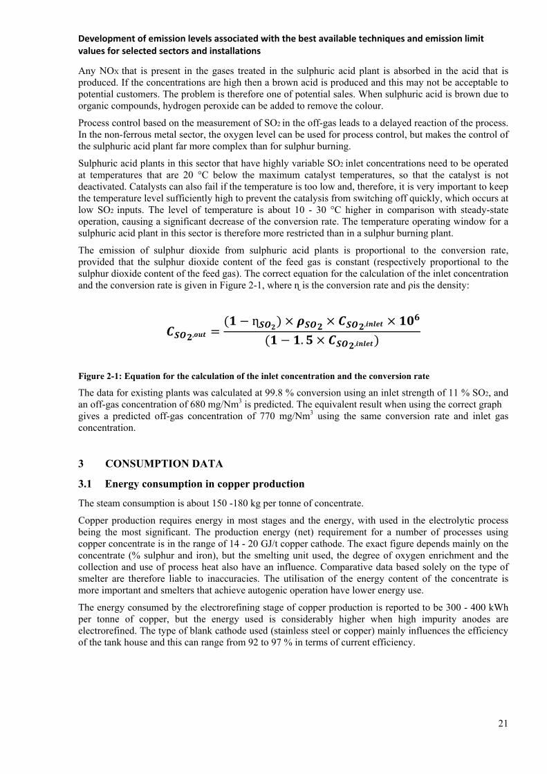
The emission of sulphur dioxide from sulphuric acid plants is proportional to the conversion rate, provided that the sulphur dioxide content of the feed gas is constant (respectively proportional to the sulphur dioxide content of the feed gas). The correct equation for the calculation of the inlet concentration and the conversion rate is given in Figure 2-1, where ɳ is the conversion rate and ρis the density:
,
ɳ ,
. ,
Figure 2-1: Equation for the calculation of the inlet concentration and the conversion rate
The data for existing plants was calculated at 99.8 % conversion using an inlet strength of 11 % SO2, and an off-gas concentration of 680 mg/Nm3 is predicted. The equivalent result when using the correct graph gives a predicted off-gas concentration of 770 mg/Nm3 using the same conversion rate and inlet gas concentration.
3 CONSUMPTION DATA
3.1 Energy consumption in copper production
The steam consumption is about 150 -180 kg per tonne of concentrate.
Copper production requires energy in most stages and the energy, with used in the electrolytic process being the most significant. The production energy (net) requirement for a number of processes using copper concentrate is in the range of 14 - 20 GJ/t copper cathode. The exact figure depends mainly on the concentrate (% sulphur and iron), but the smelting unit used, the degree of oxygen enrichment and the collection and use of process heat also have an influence. Comparative data based solely on the type of smelter are therefore liable to inaccuracies. The utilisation of the energy content of the concentrate is more important and smelters that achieve autogenic operation have lower energy use.
The energy consumed by the electrorefining stage of copper production is reported to be 300 - 400 kWh per tonne of copper, but the energy used is considerably higher when high impurity anodes are electrorefined. The type of blank cathode used (stainless steel or copper) mainly influences the efficiency of the tank house and this can range from 92 to 97 % in terms of current efficiency.

Development of emission levels associated with the best available techniques and emission limit values for selected sectors and installations
22
3.2 Primary copper input and output
The input and output data for a primary smelter depends on the copper content of the concentrate, the concentration of other metals (As, Se, Hg, Ag, Au, etc.) and the use of copper scrap or other material that contain copper in the various parts of the process.
Some primary copper smelters are integrated with secondary smelting facilities or with the production of lead or zinc oxide dust from mixed concentrates, etc. The input and output data are therefore very difficult to compare. It should be noted that the main influence on the input and output data is the copper content of the concentrate or other raw material and so there may be variations of the data and comparisons are hence not significant. The recovery of copper during smelting and refining is more meaningful and is greater than 96 %.
3.3 Secondary copper input and output data
As reported above, secondary raw material can be fed into various parts of the secondary processes depending on the purity, contents of other metals and degree of surface contamination. The degree of organic contamination affects the potential emissions, and in several process stages, afterburners are used to destroy organic components such as PCDD/F, depending on the degree of organic contamination present.
Many residues are recycled within the process and to other associated processes. Producers of non-ferrous metals, for example, lead, zinc and tin, use many of the residues as raw materials for their processes. Several sites have incorporated on-site processes to recover other metals from these residues.
4 EMISSIONS TO AIR
Dust, metal compounds, organic carbon (which can result in the formation of PCDD/F) and sulphur dioxide can be emitted to air. The potential sources and relevance of potential emissions to air are shown in Table 3-1 and they are discussed later in this section. Table 3-1: Significance of potential emissions to air from copper production process
Emission Source Dust and metal
compounds PCDD/F Organic
carbon Sulphur
compounds Material handling
••
Storage of raw ••• Drying ••• • •Scrap treatment •• ••• secondary) ••• (secondary) Smelting ••• ••• secondary) •(secondary) ••• (treated in
a recovery plant)
Converting •• • (secondary) • (secondary) ••• (treated in a recovery
plant)Refining •• • (secondary) • (secondary) •Melting/Casting • (•• for alloys) • (secondary) +
CO
Ladle transfers ••• •Electrolysis Slag Treatment •• •CO
(from electric furnace)
Note. ••• more significant - • less significant

Development of emission levels associated with the best available techniques and emission limit values for selected sectors and installations
23
Oxides of nitrogen are relatively insignificant but may be absorbed in the sulphuric acid produced from a primary process; the use of oxygen enrichment can sometimes reduce the formation of nitrogen oxides by the thermal route. This depends on the point where oxygen is added, sometimes a higher concentration of nitrogen oxides is produced due to the increase in temperature, however the gas volume and total quantity is lower. Low-NOX burners can be used.
The formation of PCDD/F in the combustion zone and in the cooling part of the off-gas treatment system (de novo synthesis) may be possible. To safeguard against harmful effects on the environment, emissions must be reduced. Accordingly, off-gases have to be captured at their source of generation and routed to an off-gas-cleaning device (e.g. a capture system followed by a dust collector and scrubber).
The emissions can escape the process either as stack emissions or as diffuse emissions, depending on the abatement systems used and the quality of plant maintenance. Stack emissions are normally monitored continuously or periodically and reported by on-site staff or off-site consultants to the competent authorities.
4.1 Carbon monoxide
In addition to the emissions outlined above, melting processes using furnaces that need to maintain a reducing atmosphere can produce a significant concentration of carbon monoxide. This is particularly the case for the melting of high-grade copper in shaft furnaces in combination with shape casting or the production of wire-rod, as the products require controlled oxygen levels to obtain high conductivity. The process therefore operates under reducing conditions and the carbon monoxide content of the gases may be elevated, with a typical levels of approximately 5000 mg/Nm³. The burner control systems that are used can also minimise CO and maintain product quality. CO alarms can also be incorporated into the process. Typical CO production in a shaft furnace used for wire-rod or semis production is 2000 to 11000 grams per tonne of copper. In some installations, afterburning is used to remove hydrocarbons from the gases when scrap coated with organic matter is processed. CO is also destroyed at the same time and the emissions are reported to be ~ 45 grams per tonne of copper.
It is possible to predict ground level concentrations of CO and this may be used to determine the effect of CO on local air quality, so that further abatement needs can be assessed locally. CO elimination by combustion of the shaft furnace gases with these levels of CO would require additional fuel, and consequently the emissions of CO2 would increase exponentially.
Carbon monoxide is also produced during the operation of the slag-cleaning furnace and the blast furnace and in some circumstances can be emitted in the off-gases. Afterburning can be used to remove the CO, giving typical concentrations in the range of 10 to 200 mg/Nm³. There is at least one example where oxygen is lanced into the top of a blast furnace above the reaction zone to provide an afterburning zone in the furnace body. This measure also destroys organic compounds such as PCDD/F. The electric furnaces used for slag cleaning and reduction processes are normally operated with afterburning, either within the furnace or in a special reaction chamber.
4.2 Dust and metal compounds
These can be emitted from most stages of the process. The techniques for dealing with emissions should be used to prevent and minimise these emissions.
Direct and diffuse dust emissions from the smelting, converting and refining stages are potentially high. The significance of the emissions is also high as these process stages are used to remove volatile metals such as Zn, Pb some As and Cd from the copper and these metals are present in the gas and partly in the dust.
The primary smelters usually contain dust very well and are effectively sealed to minimize diffuse emissions; concentrate burners or lances are used and are therefore easier to seal. Good maintenance of the furnaces and ducts is practised to minimise diffuse emissions, and the collected gases are treated in dust removal systems prior to the sulphur recovery processes.

Development of emission levels associated with the best available techniques and emission limit values for selected sectors and installations
24
Secondary smelters are more prone to diffuse emissions during charging and tapping cycles. These furnaces have large charging doors and the warping and miss-sealing of these doors is a significant factor. In secondary bath smelters, the burden is charged via an enclosed charging system, diffuse emissions occur at the tap-hole and runners, and are captured by hoods and routed to the gas-cleaning system. The gases that are collected are usually cooled and dust is removed from gas streams by electrostatic precipitators or fabric filters. High filtration efficiency is usually achieved and dust concentrations after abatement are in the range of <1 – 5 mg/Nm³.
Because of the batch mode of operation, the conversion and fire-refining stages cannot usually be sealed as well as in the smelting stage. The feeding and transfer of matte, slag and metal is a significant potential source of diffuse fumes. More importantly, the use of a ladle or boat transfer system can inhibit the effectiveness of fume collection hoods, particularly with the Peirce-Smith or similar style of converters. To capture or reduce emissions occurring during charging or emptying, converters are either enclosed or provided with secondary capture hoods. The off-gas extracted from the enclosure or hood should be treated in a manner depending on the SO2 content. Gases from matte conversion will have higher concentrations of SO2 and in all cases, metal oxides (As, Pb, etc.) need to be removed. Through hoods additions of flux and other material can minimise the rollout time of converters and so reduce the time when converters are separated from the primary gas collection system. The production of higher-grade matte reduces the number of ladle transfers and therefore reduces the potential for fumes. Diffuse or non-collected emissions are therefore very important. These issues are dependent on efficient and effective primary and, in some cases, secondary fume collection.
The melting and casting stages used during the production of wire-rod, semis, etc. are also potential sources of dust and metals. The production of copper alloys, such as brasses, results in significant fumes (ZnO) at the casting stage and these require efficient collection. The dust burden is generally low but heat/energy recovery, if practicable, can be used. Efficient fume collection and fabric filters are usually used.
Emissions of metals are strongly dependent on the composition of the dust produced by the processes. The composition varies widely and is influenced by the process that is the source of dust and by the raw materials that are being processed. For example the dust produced from a scrap converter is totally different from that of a matte converter and this will vary depending on the operating phase of the process (charging, blowing, casting, poling, etc.) at the time of the measurement, on the input material, etc. Table 3-2 show the percentage of metals in the dust from various processes.
Table 3-2: Main constituents of dust from copper processes
Component
Concentrate to matte smelting furnace ESP
dust
Blast furnace dust
Scrap converter
dust
Matte converter ESP dust
Electric slag cleaning furnace
dust
Anode furnace
dust
Pb% 0.1 -5 5-50 5 - 30 2- 25 2-15 2-20 Zn% 0.1 –10 20- 60 25-70 5- 70 25-60 5-40 Sn% 0.1 - l 0.2 -5 1- 20 0.1 – 4 Cu% 5 - 30 2 - 12 2-15 10- 25 0.5 -2.5 15-25 As% 0.1- 4 0.5 –10Ni% 0.1 -l 0.1-1 0.1 -1
4.3 Organic carbon compounds
Organic carbon compounds can be emitted during primary production from the drying stage depending on materials used for ore treatment and the fuel used for drying. For secondary production, the most significant sources are from the scrap treatment, smelting and refining stages. The conversion stage for secondary copper is also a potential source if scrap contaminated with organic material is added to the converter and complete combustion is not achieved; this is particularly the case for diffuse emissions.
Development of emission levels associated with the best available techniques and emission limit values for selected sectors and installations
25
Organic carbon compounds can be emitted if oily material is used as feed and can account for 5 - 100 g per tonne of copper or between 1 and 10 mg/Nm³.
4.4 PCDD/F
The organic carbon compounds that can be emitted include PCDD/F, resulting from the poor combustion of oil and plastic in the feed material and from de novo synthesis if the gases are not cooled rapidly enough. Scrap treatment to remove organic contamination can be practised but more usually afterburners are used to treat the gases produced followed by rapid cooling. In cases where it is not possible to treat the gases from the furnaces in an afterburner, they can be oxidised by adding oxygen above the melting zone. It is also possible to identify organic contamination of secondary raw materials so that the most appropriate furnace and abatement combination can be used to prevent the emissions of smoke and fumes and the associated PCDD/F. Melting scrap that is contaminated with organic material is also a potential source of PCDD/F in the semis industry.
It has been reported that, in the case of primary smelting and converting, the high operating temperatures used destroy organic components and the presence of sulphur dioxide inhibits denovo synthesis of PCDD/F.
The techniques used for the abatement of PCDD/F in this sector include afterburning, controlled gas handling and cooling and effective dust removal; activated carbon adsorption is also used.
If major amounts of electronic scrap with brominated flame retardants are used as feed stocks, this may result in the formation of mixed halogenated dioxins. In the case of copper remelting/refining, the conditions may exist for the formation of PCDD/F, in particular when using scrap materials and chips contaminated with chlorine from the cutting fluids used.
4.5 Sulphur dioxide
The most significant sources of sulphur dioxide are the roasting, smelting and converting stages of primary copper production using sulphide concentrates. Diffuse emissions are expected but can be collected in several ways. Sulphur dioxide can also be emitted from the concentrate drying stage (mainly from the fuel used in the burner) and from the primary refining stages where the blister copper contains 0.03 to 0.1 % dissolved sulphur. The concentration in the gas is usually very low and simple scrubbing of the gases is generally used if required.
If not applying partial roasting and calcine smelting to matte in separate units because of special feed material, the roasting of copper concentrates is carried out simultaneously with smelting. The use of sealed furnaces for smelting allows the sulphur dioxide to be collected efficiently. All of the smelters in the EU-27 use oxygen enrichment that produces a high sulphur dioxide concentration. This therefore allows the off-gas volumes to be minimised and the gas handling systems including the sulphuric acid plants to be reduced in size. Very high levels of oxygen enrichment can increase the concentration of sulphur trioxide in the gases passing to an acid plant. This increased amount of sulphur trioxide in the gas from the furnace is absorbed in the scrubbers and increases the amount of weak acid for treatment, other uses or disposal. Contact sulphuric acid plants with four or five passes are used to convert the gases. In some cases, single contact plants are used if there is a low (<5 %) sulphur dioxide content, otherwise double contact plants are used. If required, liquid sulphur dioxide can be produced from part of the sulphur dioxide contained in the gas.
The matte conversion stage also produces a significant concentration of sulphur dioxide. There are two potential problems when using batch fed converters such as the Peirce-Smith or similar style of converter. Firstly, gas collection is not totally efficient. Secondly, the sulphur dioxide concentration in the gases varies significantly depending on the stage of conversion and can cause problems with sulphur dioxide removal systems unless they are designed specifically to take account of this variation. These gases are mixed with the steady, more concentrated gases produced by the primary smelter to maintain autothermal operation of the sulphuric acid plant. Using several converter sin a phased sequential operation combining the off-gases can also reduce this effect.

Development of emission levels associated with the best available techniques and emission limit values for selected sectors and installations
26
Continuous processes such as the Mitsubishi process and the Kennecott/Outotec flash smelt/flash conversion process maintain a high and constant concentration of sulphur dioxide and do not need ladle transfers.
The gas volumes that are produced are consequently lower. This means that the concentration of sulphur dioxide is higher in the effluent gas but the mass is much smaller, at least during gas handling, cleaning and cooling. In the contact plant, the SO2 to O2 ratio should be adjusted and the SO2 concentration is diluted down to the maximum tolerable concentration.
After heat recovery and cleaning of the gases, the sulphur dioxide in the gas from the smelting stages is converted to sulphur trioxide (SO3). Sulphuric acids plants in the European copper industry have a conversion efficiency reported as 99.5 to more than 99.9 % (excluding start-up, etc.). A very small amount of SO3 is not absorbed and is emitted together with the residual SO2. During start-up and shutdown there may be occasions when weak gases are emitted. These events need to be identified for individual installations and many companies have made significant improvements to the process control equipment to reduce these emissions. The height of the stack used for the acid plant gases usually takes these factors into account to reduce local impact. Sulphur dioxide may also be present in the gases produced during secondary smelting stages due to the sulphur content of the fuel or raw materials. In some cases, scrubbers are used to remove the SO2 and in one case the gases from an electric furnace (and a Cu/Pb converter) are diverted to a primary copper smelter sulphuric acid plant when certain raw materials are present.
4.6 Diffuse emissions
In pyrometallurgical plants, diffuse emissions may occur both during charging and tapping operations as well as during the transfer of the molten products or intermediates from one operation to another. Of particular importance in this connection is the fact that the prevailing temperatures of the various metal, slag or matte fractions are above the volatilisation points of the low boiling accompanying metals (e.g. Zn, Pb and Sn) and their oxides, so that the latter accumulate in the emitted vapours. As far as possible, diffuse emissions should be captured at the source via secondary hoods and the extracted off-gas is to be routed to the gas-cleaning system.
In secondary smelters with the low dust loads of the secondary hood off-gas, it is sometimes advantageous to combine this off-gas stream with the furnace off-gas prior to cleaning; since this can improve the filtration properties of the total off-gas stream. Further diffuse emissions may occur during transport due to the resuspension of dust, the handling of the molten materials, in particular, during transfer or pouring operations. Moreover, dust emissions are generated during the handling and pretreatment of the secondary raw materials (e.g. size reduction, shredding, pelletising). The emission at secondary copper smelters can be dominated by diffuse dust emissions which account for approximately 70 % of total emissions.
4.7 Nitrogen oxides
The production stages for copper usually rely on high temperatures but are also associated with the use of oxygen. This reduces the partial pressure of nitrogen in the flame and reduces nitrogen oxide formation, provided that nitrogen is not present in great amounts in the very hot areas. Typical levels for the emissions of nitrogen oxides for secondary copper are reported to be in the range of 50 to 500 mg/Nm³, depending on the furnace and type of operation. For NOX, the use of highly efficient processes (e.g. Contimelt) requires a balance to be established locally between energy use and achieved value.
Nitrogen oxides from primary processes are mainly absorbed in the sulphuric acid produced.
4.8 Summary of air emissions
Emissions are summarisedin Table 3-3, and Table 3-4.

Development of emission levels associated with the best available techniques and emission limit values for selected sectors and installations
27
Table 3-3: Specific emissions to air from some primary and secondary processes
Process type Dust g/t of product metal
Sulphur dioxide g/t of
product metal
Cu g/t of product metal
Pb g/t of product metal
As g/t of product
metal
Primary Cu 130 - 800 6000 -18000 25-130 6-45 2-27Secondary Cu 100 - 1000 500 -3500 8-100 10-60 0.5-5Melt shop semis fabrication
21 N/A 4 N/A 0.15
Wire-rod Production
10 N/A 4 N/A 0.05
Table 3-4: Emissions and operating data from converters in secondary copper production
Operating parameter Unit Typical value or range
Scrap converter Matte converter
Converter copper yield per batch (t) 8-25 30-300
Number of batches per day
4-6 2-3
Batch duration (h) 4-6 5-8 Blowing time/batch (h) 2-3.5 4-7 Raw gas (including secondary hood off-gas) Volumetric off-gas flow (m³/h) 80000-150000 80000-150000 Dust content (mg/m³) 10000-30000 10000-30000 Main dust constituents (depending on operating mode) Zn (% by mass) 25-70 1-10 Sn (% by mass) 1-20 1-5 Pb (% by mass) 5-30 30-55 Clean gas (including secondary hood off-gas) Dust content (1) (mg/m³) 1-5 - (2) SO2 (mg/m³) 200-500 (3) - (2) NOX (expressed as NO2) (mg/m³) 20-30 - (2) Off-gas temperature at stack outlet (°C) 80-90 - (2)
(1) For dust constituents, see Table 3-2 (2) Matte converter off-gases are routed to the contact process unit for sulphuric acid production. (3) Continuous monitoring: daily mean value <500 mg/m³ ; max. half-hour mean value <1500 mg/m³
5 BAT CONCLUSIONS
5.1 Environmental management systems (EMS)
1. In order to improve the overall environmental performance of non-ferrous metal plants, BAT is to implement and adhere to an environmental management system (EMS) that incorporates all of the following features:
a. commitment of the management, including senior management; b. definition of an environmental policy that includes the continuous improvement of the installation
by the management; c. planning and establishing the necessary procedures, objectives and targets, in conjunction with
financial planning and investment; d. implementation of procedures paying particular attention to:
i. structure and responsibility

Development of emission levels associated with the best available techniques and emission limit values for selected sectors and installations
28
ii. training, awareness and competence iii. communication iv. employees involvement v. documentation
vi. efficient process control vii. maintenance programmes
viii. emergency preparedness and response ix. safeguarding compliance with environmental legislation;
e. checking performance and taking corrective action, paying particular attention to: i. monitoring and measurement (see also the Reference Document on the General Principles of
Monitoring) ii. corrective and preventive action
iii. maintenance of records iv. independent (where practicable) internal and external auditing in order to determine whether
or not the EMS conforms to planned arrangements and has been properly implemented and maintained;
f. review of the EMS and its continuing suitability, adequacy and effectiveness by senior management;
g. following the development of cleaner technologies; h. consideration for the environmental impacts from the eventual decommissioning of the
installation at the stage of designing a new plant, and throughout its operating life; i. application of sectorial benchmarking on a regular basis.
Applicability
The scope (e.g. level of details) and nature of the EMS (e.g. standardised or non-standardised)will generally be related to the nature, scale and complexity of the installation, and the range of environmental impacts it may have.
5.2 Energy management
2. In order to use energy efficiently, BAT is to use a combination of the following techniques:
Technique Applicability
a Energy efficiency management system (E2MS) Generally applicable for new plants and for major upgrades of existing plants
b Regenerative or recuperative burners Generally applicable for shaft furnaces c Production of steam or hot water from waste process heat Generally applicable d Regenerative afterburners Generally applicable e Preheat the furnace charge, combustion air or fuel using the
hot gases from the melting stage Applicable for roasting or smelting of sulphide ore/concentrate and for other pyrometallurgicproceses
f Preheat the combustion air using the hot gases from the launders
Applicable for pyrometallurgic proceses
g Oxygen-enriched air or pure oxygen in the burners to reduce energy consumption by allowing autogenic smelting or the complete combustion of carbonaceous material
Applicable for furnaces that use sulphur or carbon raw materials contents
h Low mass refractory Applicability may be restricted by the durability of the furnace lining and metal infiltration into the lining
i Drying of concentrates and raw wet materials at low temperatures before smelting
Generally applicable
j Recirculate contaminated waste gas back through an oxy-fuelburner to recover the energy of the total organic carbon
Generally applicable

Development of emission levels associated with the best available techniques and emission limit values for selected sectors and installations
29
present k Suitable insulation for high temperature installations such
as steam and hot water pipes Generally applicable
l Use the heat generated from the production of sulphuric acid from the sulphur dioxide to preheat gas directed to the sulphuric acid plant or to generate steam and/or hot water
Applicable for non-ferrous metals plants including sulphuric acid or liquid SO2 production
m Use high efficiency electric engines equipped with a frequency drive for equipment, such as fans
Generally applicable
n Control systems that automatically activate switch on dust or fume extraction only when no emissions are arise
Generally applicable
Description (i) A low-mass refractory absorbs less heat due to its lower density. Furnaces can be heated and cooled using less energy. The thermal efficiency of the furnace could be also improved because the lower thermal conductivity of a low-mass refractory allows the lining to be thinner and therefore the furnace can be smaller. As the furnace is smaller, there is a lower surface exposure and so less heat is lost. The fast response of the low-mass refractory to temperature changes also allows more accurate control, and uniform temperature distribution within the furnace. 3. In order to use energy efficiently in primary copper production, BAT is to use a combination of the following techniques:
Technique Applicability
a Flash smelting furnaces Generally applicable for new plants and for major upgrades of existing plants
b Using the hot process gases from the melting stages to heat up the incoming charge
Generally applicable for shaft furnaces
c Covering the concentrates during transport and storage Generally applicable d Using the excess heat produced during primary smelting or
converting stages to melt secondary containing copper materials
Generally applicable
4. In order to use energy efficiently in secondary copper production, BAT is to use a combination of the following techniques:
Technique Applicability
a Reducing the water content of feed material Generally applicable d To melt scraps using the excess heat that is produced
during smelting or converting process Generally applicable
5.3 Process control and emissions monitoring
5. In order to achieve a stable process operation, BAT is to implement a process control system, and to use a combination of the following techniques:
Technique Applicability
a Inspection and selection of input materials according to the process and the abatement techniques applied
Generally applicable
b Good mixing of different feed materials to achieve optimum conversion efficiency and reduce emissions and rejects
Generally applicable

Development of emission levels associated with the best available techniques and emission limit values for selected sectors and installations
30
c Feed weighing and metering systems Generally applicable
d Microprocessors to control material feed rate, critical process conditions including the alarm, combustion conditions and gas additions.
Generally applicable
e On-line monitoring of temperature, furnace pressure and gas flow
Applicable to all furnaces
f Monitoring of gaseous components (e.g. O2, CO) to control critical process parameters
Generally applicable
g Monitoring of dust and mercury in the off-gas before sending to the sulphuric acid plant
Applicable for non ferrous metals plants including sulphuric acid or liquid SO2 production
h On-line monitoring of vibrations to detect blockages and possible equipment failure
Generally applicable
j Temperature monitoring and control to prevent the production of metal and metal oxide fumes through overheating
Applicable to melting smelting furnaces
6. BAT is to monitor the stack emissions to air mentioned in the following table with at least the minimum frequency given and in accordance with EN standards. If EN standards are not available, BAT is to use ISO, national or other international standards which ensure the provision of data of an equivalent scientific quality.
Parameter Minimum monitoring frequency (1)
a Dust (2) Continuous or periodic (at least three consecutive measurements once per year)
b Lead and its compoundsexpressed as Pb Periodic (at least three consecutive measurements once per year)
c Arsenic and its compoundsexpressed as As Periodic (at least three consecutive measurements once per year)
d SOxexpressed as SO2 Continuous or periodic (at least three consecutive measurements once per year)
e NOxexpressed as NO2 (3) Periodic (at least three consecutive measurements once per year)
f TOC as C Continuous or periodic (at least three consecutive measurements once per year)
g VOC Yearly mass balance h PCDD/F Periodic (at least one measurement once peryear) i H2SO4 Periodic (at least three consecutive
measurements once per year) (1) More frequent monitoring (including the selection between continuous or periodic measurements) shouldbe based on local environmental conditions and plant specificities such as capacity, type of raw materials used, etc. (2) For small dust emission sources (< 10 000 Nm3/h) from the storage and handling of raw materials, monitoring could be based on the measurement of surrogate parameters (such as the pressure drop). (3) For furnaces using oxygen enriched burners, the emissions are expressed in terms of grams of NOx
emitted per tonne of melted metal produced, as an average over the sampling period for the continuous smelter/melter process. For the batch smelter/melter process, the emissions are expressed as an average of all the batch process operations.

Development of emission levels associated with the best available techniques and emission limit values for selected sectors and installations
31
5.4 Air emissions
7. In order to reduce secondary emissions to air from furnaces and auxiliary devices in primary copper production and to optimise the performance of the abatement system, BAT is to collect, mix and treat secondary flue-gases in a centralised flue-gas cleaning system.
Description Secondary flue-gases from various sources are collected, mixed, and treated in a single centralised flue-gas cleaning system, designed to accommodate effectively the pollutants present in each of the flows. Care should be taken to avoid chemical reactions among the different collected flows. Applicability Applicable for secondary flue-gases that are chemically compatible. The applicability may be limited by the design and layout of the existing plants.
5.4.1 Diffuse emissions
8. In order to prevent or reduce diffuse emissions and to optimise the efficiency of off-gas collection, BAT is to use a combination of the following techniques:
Technique Applicability
a Application of thermal or mechanical pretreatment to minimise organic contamination of the furnace feed
Applicable for secondary raw materials
b Sealing of furnaces and other process units Generally applicable c Use of semi-sealed furnaces only where sealed furnaces are
not available Generally applicable
d Dust or fume collection where material transfers take place Generally applicable e Optimisation of the design and operation of hooding and
ductwork to capture fumes arising from hot metal, matte or slag transfers and tapping.
Generally applicable
f Furnace or reactor enclosures such as 'House-in-House' or 'Dog House' to prevent the emission of fumes into the air
Generally applicable
g Computerised fluid dynamics studies and tracers to model the flow of furnace gases
Generally applicable
h Charging systems to add raw materials in small portions Applicable for semi closed furnaces 9. In order to prevent diffuse emissions from the storage of raw materials, BAT is to use acombination of the following techniques:
Technique Applicability
a Enclosed buildings or silos/bins Applicable to the storage of dust-forming materials such as concentrates, fluxes and fine materials
b Covered storage Applicable to the storage of non-dust-forming materials such as concentrates, fluxes, solid fuels and coke and secondary materials that contain water soluble organic compounds
c Sealed packaging Applicable to the storage of dust-forming materials or secondary materials that contain water soluble organic compound
d Covered bays Applicable if the material has been

Development of emission levels associated with the best available techniques and emission limit values for selected sectors and installations
32
pelletised/agglomerated e Dust/gas extraction devices placed at the
transfer and tipping points Applicable to the storage of dust forming materials
f Cleaning regularly the storage area and, when needed, moistening with water
Generally applicable
g Placing the longitudinal axis of the heap parallel with the prevailing wind direction
Applicable if outdoor storage is used
h Protective planting, windbreak fences or upwind mounts to lower the wind velocity
Applicable if outdoor storage is used
i One heap instead of several ones where feasible
Applicable if outdoor storage is used
10. In order to prevent diffuse emissions from the handling and transport of raw materials, BAT is to use a combination of the following techniques:
Technique Applicability
a Enclosed conveyors or pneumatic systems to transfer and handle dust-forming concentrates and fluxes and fine grained material
Generally applicable
b Covered conveyors to handle non dust-forming solid materials
Generally applicable
c Extraction of dust from delivery points, silo vents, pneumatic transfer systems and conveyor transfer points, and connection to a filtration system
Applicable to dustforming materials
d Closed bags or drums to handle materials with dispersible or water soluble components
Generally applicable
e Suitable containers to handle palletised materials Generally applicable f Sprinkling to moister the materials at handling points Generally applicable g Keep transport distances as short as possible Generally applicable
h Reduce the drop height of conveyor belts, mechanical shovels or grabs
Generally applicable
i Adjust the speed of open belt conveyors (<3.5 m/s) Applicable when open belt conveyors
are used
j Minimise the speed of descent or free fall height of the materials
Generally applicable
k
Placement of transfer conveyors and pipelines in safe, open areas above ground so that leaks can be detected quickly and damage from vehicles and other equipment can be prevented. If buried pipelines are used for nonhazardous materials, their course should be documented and marked and safe excavation systems adopted
Generally applicable
l Automatic resealing of delivery connections Applicable for liquid and liquefied gas
handling
m Back venting of displaced gases to the delivery vehicle to reduce emissions of VOCs.
Generally applicable
n Washing of wheels and chassis of vehicles used to deliver or handle dusty materials
Not applicable when ice could be formed
o Use of planned campaigns for road sweeping Generally applicable
p Segregation of incompatible materials (e.g. oxidising agents and organic materials)
Generally applicable
q Minimisation of material transfers between processes Generally applicable

Development of emission levels associated with the best available techniques and emission limit values for selected sectors and installations
33
11. In order to prevent or reduce diffuse emissions from material pretreatment (such as blending, drying, mixing, homogenisation, screening and pelletisation) of primary and secondary materials, BAT is to use one or a combination of the following techniques:
Technique Applicability
a Use of enclosed conveyers or pneumatic transfer systems
Generally applicable for dusty materials
b Carrying out activities with dusty materials such as mixing in a enclosed building
Generally applicable. For existing plants, application may be difficult due to the space requirements
c Use of dust suppression systems such as water cannons or water sprinklers
Applicable for mixing operations carried out outdoors. Not applicable for process that requires dry materials. The application is also limited in region with water shortage or with very low winter temperature
d Use of enclosed equipment with gas extraction system, connected to an abatement system
Applicable for feed blend prepared with a dosing bin or loss-in-weight system, for drying, mixing, milling, air separation and pelletisation
e Use of an extraction system such as a hood in combination with a dust and gas abatement system
Generally applicable for dusty and gaseous emissions
12. In order to prevent or reduce diffuse emissions from charging, smelting and tapping operations in primary and secondary copper smelters and from holding and melting furnaces, BAT is to use a combination of the following techniques:
Technique Applicability
a Briquetting and pelletisation of raw materials Applicable only when the process and the furnace can use pelletised raw materials
b Enclosed charging system such as single jet burner, double bell, closed conveyers or feeders equipped with a gas extraction system in combination with a dust and gas abatement system
Generally applicable depending on the type of furnaces. The jet burner is applicable only for flash furnaces
c Sealed or enclosed furnaces with door sealing Generally applicable d Operating the furnace and gas route under negative
pressure and a sufficient gas extraction rate to prevent pressurisation
Generally applicable
e Charging systems to add raw materials in small portions
Applicable for semi-closed furnaces
f Capture hood/enclosures at charging and tapping points in combination with an off-gas abatement system
Generally applicable
g Encapsulation of the furnace in extractable housing Generally applicable h Complete hood coverage with a gas extraction and
abatement system Generally applicable
i Maintain furnace sealing Generally applicable j Hold the temperature in the furnace at the lowest
required level Generally applicable
k Covered lauders Generally applicable l Boosted suction systems (1) Generally applicable (1) Description of the technique is given in Section 6

Development of emission levels associated with the best available techniques and emission limit values for selected sectors and installations
34
13. In order to reduce diffuse emissions from Peirce-Smith converter (PS) furnaces in primary and secondary copper production, BAT is to use a combination of the following techniques:
Technique Applicability a Operating the furnace and gas route under negative
pressure and a sufficient gas extraction rate to prevent the pressurization
Generally applicable
b Oxygen enrichment Generally applicable c Primary hood over the converter opening to collect
primary off-gases Generally applicable
d Addition of materials (e.g. scrap and flux) through the hood
Generally applicable
e System of secondary hoods in addition to the main one to capture emissions during charging and tapping operations
Generally applicable
f Furnace located in enclosed building equipped with a gas extraction and abatement system
Applicable for new plants. In existing plants or major upgrades, application may be difficult due to the space requirements
g Apply motor driven secondary hoods, to move them, according to the process stage, to increase the efficiency of the collection of secondary emissions
Generally applicable
h Boosted suction systems (1) and automatic control to prevent blowing when the converter is "rolled out" or "rolled in
Generally applicable
(1) Description of the technique is given in Section 6.
14. In order to reduce diffuse emissions from casting, BAT is to use a combination of thefollowing techniques: Technique a Use of enclosures or hoods equipped with flue-gas extraction connected to an
abatement system b Use of covering for the melts in holding and in casting furnaces c Boosted suction systems (1)
5.4.2 Channeled dust emissions
15. In order to reduce dust emissions from raw materials reception, storage, handling, transport, metering, mixing, blending, crushing, drying, cutting and screening in primary and secondary copper production, BAT is to use a bag filter. Table 5-1: BAT-associated emission levels for dust from raw materials reception, storage, handling, transport, metering, mixing, blending, crushing, drying, cutting and screening in primary and secondary copper production Parameter Unit BAT-AEL (1) Dust mg/Nm³ ≤5(1) As an average over the sampling period (periodic measurements of at least half an hour). 16. In order to reduce dust emissions from concentrate drying in primary copper production, BAT is to use one of the following techniques: Technique a Bag filter b ESP

Development of emission levels associated with the best available techniques and emission limit values for selected sectors and installations
35
Table 5-2: BAT-associated emission levels for dust from concentrate drying in primary copper production Parameter Unit BAT-AEL (1) Dust mg/Nm³ ≤10 1) As a daily average for continuous measurements or as an average over the sampling period (periodic measurements of at least half an hour).
17. In order to reduce dust and metals in primary and secondary emissions from primary copper smelters and converters, BAT is to use one or a combination of the following techniques:
Technique Applicability a Use of a dust pretreatment system, such as a cyclone,
or settling chamber in combination with one of the technique listed below
Applicable for flue-gas with a high dust content
b Bag filter Generally applicable c Wet ESP Generally applicable d ESP Generally applicable Table 5-3: BAT-associated emission levels for dust, lead and arsenic in primary and secondary emissions from primary copper smelters and converters
Parameter Unit BAT-AEL Dust mg/Nm³ ≤10 (1) Pb mg/Nm³ 1 – 3 (2) As mg/Nm³ ≤1 (2) (1) As a daily average for continuous measurements. (2) As an average over the sampling period (periodic measurements of at least half an hour). 18. In order to reduce dust and metals in primary and secondary emissions from secondary copper smelters and converters, BAT is to use one or a combination of the following techniques:
Technique
a Bag filter b Hot ESP c Wet ESP d Absorbent agent, such as activated carbon injection,
for the reduction of metals. Table 5-4: BAT-associated emission levels for dust, lead and arsenic in primary and secondary emissions from secondary copper smelters and converters
Parameter Unit BAT-AEL Dust mg/Nm³ ≤5 (1) Pb mg/Nm³ 1 – 3 (2) As mg/Nm³ ≤1 (2) (1) As a daily average for continuous measurements or as an average over the sampling period (periodic measurements of at least half an hour). (2) As an average over the sampling period (periodic measurements of at least half an hour). 19. In order to reduce dust in primary and secondary emissions from secondary copper holding furnaces, BAT is to use a bag filter.

Development of emission levels associated with the best available techniques and emission limit values for selected sectors and installations
36
Table 5-5: BAT-associated emission levels for dust in primary and secondary emissions from secondary copper holding furnaces Parameter Unit BAT-AEL (1) Dust mg/Nm³ ≤5(1) As an average over the sampling period (periodic measurements of at least half an hour). 20. In order to reduce dust and metals emissions from copper rich slag heat processing and cleaning, BAT is to use one of the following techniques:
Technique
a Bag filter b ESP Table 5-6: BAT-associated emission levels for dust and lead from copper rich slag heat processing and cleaning
Parameter Unit BAT-AEL Dust mg/Nm³ ≤5 (1) Pb mg/Nm³ 3 (2) (1) As a daily average for continuous measurements or as an average over the sampling period (periodic measurements of at least half an hour). (2) As an average over the sampling period (periodic measurements of at least half an hour). 21. In order to reduce dust and metals emissions from melting furnaces, BAT is to use a bag filter. Table 5-7: BAT-associated emission levels for dust, lead and arsenic from melting furnaces
Parameter Unit BAT-AEL Dust mg/Nm³ ≤5 (1) Pb mg/Nm³ 1 (2) As mg/Nm³ ≤1 (2) (1) As a daily average for continuous measurements or as an average over the sampling period (periodic measurements of at least half an hour). (2) As an average over the sampling period (periodic measurements of at least half an hour).
5.4.3 Organic compounds emissions
22. In order to reduce organic compounds emissions during secondary raw material drying, de-oiling, smelting and melting, BAT is to use one of the following techniques:
Technique (1) Applicability a Afterburner or post combustion chamber Generally applicable b Regenerative afterburner Not applicable when the increased
investment cost is not balanced by the reduction of the fuel expenses
(1) Descriptions of the techniques are given in Section 6 Table 5-8: BAT-associated emission levels for organic compounds during secondary raw material drying, de-oiling, smelting and melting
Parameter Unit BAT-AEL(1) TOC as C mg/Nm³ ≤ 10 (1) As a daily average for continuous measurements or as an average over the sampling period (periodic measurements of at least half an hour).

Development of emission levels associated with the best available techniques and emission limit values for selected sectors and installations
37
23. In order to reduce PCDD/F emissions in secondary copper production from smelting, melting, fire refining and converting operations, BAT is to use one or a combination of the following techniques:
Technique (1) Applicability a Selection of raw material according to the
furnace and the abatement techniques used Generally applicable
b Optimum combustion conditions Generally applicable c Use of charging systems to give small
additions of raw materials Applicable for semi-closed furnaces
d Thermal destruction of PCDD/F in the furnace at high temperatures (> 850 °C)
Generally applicable
e Use of oxygen injection in the upper zone of the furnaces
Generally applicable
f Internal burner system Generally applicable g Use of post-combustion chamber or afterburner (1) Generally applicable h Avoid exhaust system with high dust
coating for temperature > 250 °C Generally applicable
i Rapid quenching (1) Generally applicable j Use of efficient dust collection system and
injection of absorption agent (1) Generally applicable
(1) Descriptions of the techniques are given in Section 6. Description (a) The raw materials should be selected in such a way that the furnace and the abatement system used to achieve the required abatement performance could treat the contaminants contained in the feeding properly. (b) Act on combustion conditions: good mixing between air or oxygen and carbon content, control of the temperature of the gases and resident time to oxidise the organic carbon comprises PCDD/F. (c) Add raw material in small portions in semi-closed furnaces to reduce the furnace cooling effect during charging. This maintains a higher gas temperature and prevents the reformation of PCDD/F. (f) The off-gas is directed through the burner flame and the organic carbon is converted with oxygen to CO2. (h) The presence of dust at temperature above 250 °C promotes the de novo PCDD/F synthesis. (j) and (k) PCDD/F may be absorbed onto dust and hence emissions can be reduced using inefficient dust filtration system. The use of a specific absorbing agents promote this process and reduce the emission of PCDD/F. Table 5-9: BAT-associated emission levels for PCDD/F from smelting, melting, fire refining and converting operations in secondary copper production
Parameter Unit BAT-AEL(1) PCDD/F ng I-TEQ/Nm³ ≤ 0.1 (1) As an average over the sampling period (periodic measurements of at least six hours).
5.4.4 SO2 emissions
24. In order to reduce the emissions of SO2 in off-gases with variable and/or high SO2content ( > 1 % v/v SO2 but ≤ 4.5 %), BAT is to recover SO2 by producing sulphuric acid using single contact/single absorption processes in combination with primary or secondary emissions reduction measures. Description In a single contact/single absorption process, SO2 is converted into SO3 using a series of four catalyst beds, in which the SO3 reacts with water in the absorber to form H2SO4. A Wet gas Sulphuric Acid

Development of emission levels associated with the best available techniques and emission limit values for selected sectors and installations
38
(WSA) process or tail gas treatment, such as polyether-based absorption/desorption, scrubber with ZnO, is applied to increase the sulphur recovered and to reduce the emission of SO2. Table 5-10: BAT-associated emissions levels for SO2 from single contact/single absorption processes
Parameter Unit BAT-AEL(1) SO2 mg/Nm3 100 – 450 (1) As daily average based on continuous measurement. 25. In order to reduce the emissions of SO2 in off-gases with stable and high SO2 content (> 4.5 % v/v SO2), BAT is to recover SO2 by producing sulphuric acid using double contact/double absorption processes. Description In double contact/double absorption processes, SO2 is converted into SO3 using two stages of catalysis. Between the two stages, an absorber is used to remove the SO3 from the gas stream and produce liquid H2SO4. Table 5-11: BAT-associated environmental performance levels for SO2 from double contact/double absorption processes
Parameter BAT-AEPL (1) (2) (conversion rate)
BAT-AEL (2) (3) (4) (mg/Nm3) SO2 99.7 – 99.92 % 200 – 770 (1) These conversion rates relate to the conversion including the absorption tower, they do not include the effect of tail gas scrubbing. (2) As daily average based on continuous measurement. (3) The lower end of the range is associated with the use of cryogenic process or absorption in cold water followed by stripping. (4) While ensuring the achievement of the BAT-AEPL. 26. In order to reduce SO2 emissions in off-gases with a low SO2 content (< 1 % v/v SO2)from copper concentrate roasting, primary smelters and converters, BAT is to use one or a combination of the following techniques:
Technique Applicability a Dry or semi-dry scrubber Generally applicable b Wet scrubber For existing plants, applicable if the waste water
treatment plant could treat the pollutant present into the scrubber´s effluent and the resulting water can be discharged
c Polyether-based absorption/desorption system
Not applicable when sulphuric acid or liquid SO2 plants are not available
Table 5-12: BAT-associated emission levels for SO2 in off-gases with a low SO2 content (< 1 % v/v SO2) from copper concentrate roasting, primary smelters and converters Parameter Unit BAT-AEL (1) (2) SO2 mg/Nm3 200 – 500 (1) As a daily average for continuous measurements. (2) The lower end of the range is associated with the use of a wet scrubber.

Development of emission levels associated with the best available techniques and emission limit values for selected sectors and installations
39
27. In order to reduce SO2 emissions in off-gases with a low SO2 content (< 1 % SO2) from secondary copper smelters and converters, BAT is to use one or a combination of the following techniques:
Technique Applicability a Dry or semi-dry scrubber Generally applicable b Wet scrubber For existing plants, applicable if a suitable waste water
treatment plant is available and the resulting water can be discharged
Table 5-13: BAT-associated emission levels for SO2 in off-gases with a low SO2 content (< 1 % v/v SO2) from secondary copper smelters and converters Parameter Unit BAT-AEL (1) (2) SO2 mg/Nm3 100 – 300 (1) As a daily average for continuous measurements. (2) The lower end of the range is associated with secondary copper production using raw materials with low sulphur content. 28. In order to reduce SO2 emissions from copper rich slag heat processing and cleaning, BAT is to use one or a combination of the following techniques:
Technique Applicability a Dry or semi-dry scrubber Generally applicable b Wet scrubber For existing plants, applicable if the waste water treatment
plant could treat the pollutant present into the scrubber´s effluent and the resulting water can be discharged
Table 5-14: BAT-associated emission levels for SO2 from copper rich slag heat processing and cleaning Parameter Unit BAT-AEL (1) SO2 mg/Nm3 ≤ 200 (1) As a daily average for continuous measurements or as an average over the sampling period (periodic measurements of at least half an hour). 29. In order to reduce SO2 emissions from melting and casting in primary and secondary copper production, BAT is to use one of the following techniques:
Technique Applicability a Dry or semi-dry scrubber Generally applicable b Wet scrubber For existing plants, applicable if the waste water treatment
plant could treat the pollutant present into the scrubber´s effluent and the resulting water can be discharged
Table 5-15: BAT-associated emission levels for SO2 from melting and casting in primary and secondary copper production Parameter Unit BAT-AEL (1) SO2 mg/Nm3 ≤ 300 (1) As a daily average for continuous measurements or as an average over the sampling period (periodic measurements of at least half an hour).

Development of emission levels associated with the best available techniques and emission limit values for selected sectors and installations
40
5.4.5 Reduction of NOx emissions
30. In order to prevent NOx emissions from pyrometallurgical processes, BAT is to use one of the following process-integrated techniques: Technique (1) Applicability a Low-NOX burners
Generally applicable b Oxy-fuel burners c Flue-gas recirculation back through the burner to reduce the
temperature of the flame Applicable for oxy-fuel firing burners
(1) Descriptions of the techniques are given in Section 6.
6 DESCRIPTION OF TECNIQUES
The techniques described below are listed according with the main pollutant they are aimed to abate, which does not prevent them from having a positive impact in the reduction of other pollutants.
6.1 Dust emissions
Technique Description Bag or fabric filter Bag filters are constructed from porous woven or felted fabric
through which gases flow through and particles are removed by use of a sieve or other mechanism. Use of a fabric filter requires a fabric material selection suited to the characteristics of the waste gases and the maximum operating temperature. Cartridge filters are a variation of fabric filter that uses cartridges instead of bags
Cyclone Cyclones use inertia in order to remove particulate matter from waste gas streams, by imparting centrifugal forces, usually within a conical chamber
Electrostatic precipitator (ESP) Electrostatic precipitators operate such that particles are charged and separated under the influence of an electrical field. They are capableof operating over a wide range of conditions.
Wet electrostatic precipitator (Wet ESP)
The technique consists of an electrostatic precipitator in which the collected material is removed from the plates of the collectors by flushing with a suitable liquid, usually water. Some mechanism is usually installed to remove water droplets before discharge of the waste gas (e.g. a demister or a last dry field).
Hot electrostatic precipitator (Hot ESP)
Hot electrostatic precipitators are electrostatic precipitators specially designed to operate with high-temperature off-gases (> 300 ºC)
Settling chamber/gravitational separator
Settling chamber/gravitational separators are used to separate particulate matter from waste gas streams by use of gravity/mass inertia. The separating effect is increased by reducing the waste gas velocity (e.g. by baffles, lamellae or metal gauze)
Ceramic and metal mesh filter Low density ceramic filters operate in a similar manner to fabric filters as far as operating principles, general arrangement and cleaning operations are concerned. Instead of cloth bags and their metal supports, rigid elements that resemble candle filters are used
Wet dust scrubber Wet dust scrubbing is a variation of wet gas scrubbing, which can additionally recover/abate particulate matter. Wet dust scrubbing entails separating the dust by intensively mixing the incoming gas with water, mostly combined with a removal of the coarse particles through the use of centrifugal force. In order to achieve this, the gas is released inside tangentially. The removed solid dust is collected at the bottom of the dust scrubber. Aside from the dust, inorganic chemicals such as SO2, NH3, NH4Cl, VOC and heavy metals that may be attached to the dust are removed

Development of emission levels associated with the best available techniques and emission limit values for selected sectors and installations
41
6.2 Mist emissions
Technique Description Demister Demisters are filter devices that remove entrained liquid droplets
from a gas stream. They consist of a woven structure of metal or plastic wires, with a high specific surface. Through their momentum, small droplets present in the gas stream impinge against the wires and coalesce into bigger drops
Centrifugal system Centrifugal systems use inertia in order to remove droplets from offgas streams by imparting centrifugal forces
6.3 NOx emissions
Technique Description Low-NOxburner Low-NOx burners reduce the formation of NOx by controlling peak
flame temperature, the availability of oxygen and the residence time in the combustion zone through the staged addition of combustion airand/or fuel and they may also include partial flue-gas recirculation
Oxy-fuel burner The technique involves the replacement of the combustion air with oxygen, with consequent elimination/reduction of thermal NOx
formation from nitrogen entering the furnace. The residual nitrogen content in the furnace depends on the purity of the oxygen supplied, on the quality of the fuel and on the potential air inlet.
Flue-gas recirculation Implies the reinjection of waste gas from the furnace into the flame to reduce the oxygen content and therefore the temperature of the flame. The use of special burners is based on internal recirculation of combustion gases which cool the root of the flames and reduce the oxygen content in the hottest part of the flames
6.4 SO2 emissions
Technique Description Dry and semi-dry scrubber Dry powder or a suspension/solution of alkaline reagent are
introduced and dispersed in the waste gas stream. The material reacts with the sulphur gaseous species to form a solid which has to be removed by filtration (bag filter or electrostatic precipitator). The use of a reaction tower improves the removal efficiency of the scrubbing system
Dry and semi-dry scrubber In the wet scrubbing process, gaseous compounds are dissolved in an alkaline solution. Downstream of the wet scrubber, the flue-gases are saturated with water and a separation of the droplets is required before discharging the flue-gases. The resulting liquid has to be treated by a waste water process and the insoluble matter is collected by sedimentation or filtration
Sulphuric acid plant In this process, the sulphur dioxide in the gas is converted to sulphur trioxide in a contact process when the gases are passed through a vanadium pentoxide catalyst bed. Sometimes the catalyst is doped with caesium oxide, which improves performance particularly when the SO2 concentration is low and variable or when the temperature is low. Single and double contact plants are used, being the latter the most commonly applied
Liquid SO2 plant Sulphur dioxide is absorbed in cold water (e.g. cold seawater)
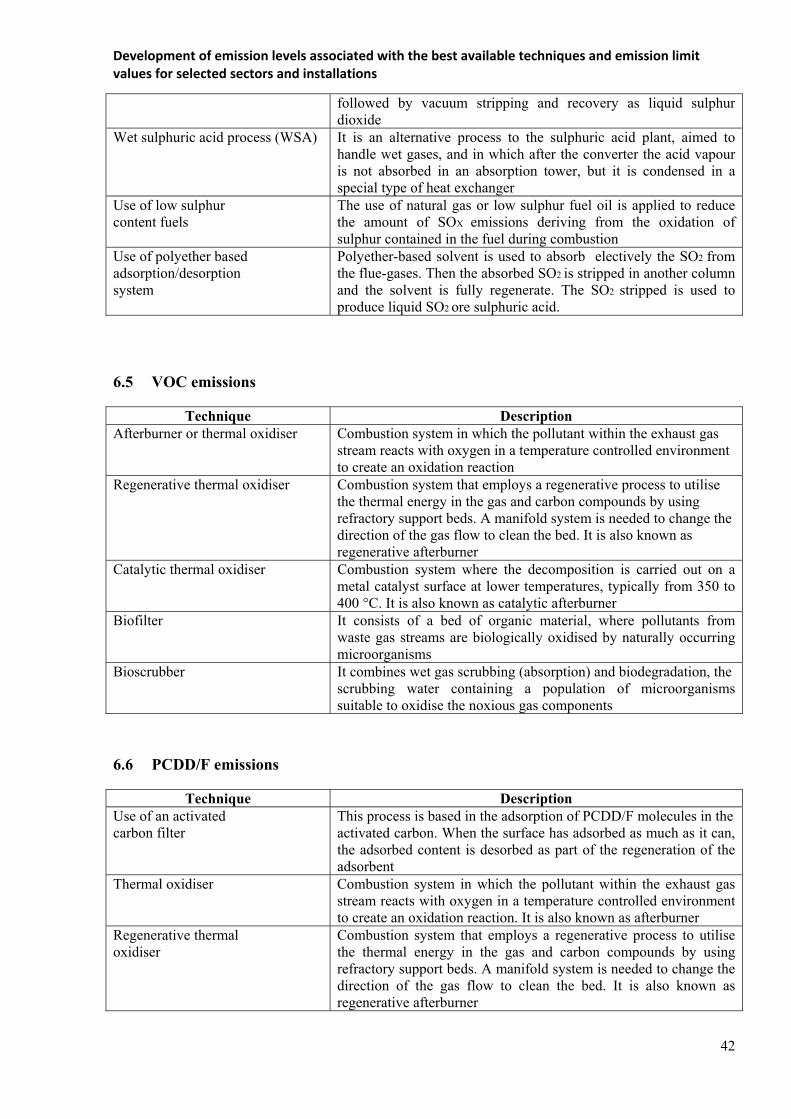
Development of emission levels associated with the best available techniques and emission limit values for selected sectors and installations
42
followed by vacuum stripping and recovery as liquid sulphur dioxide
Wet sulphuric acid process (WSA) It is an alternative process to the sulphuric acid plant, aimed to handle wet gases, and in which after the converter the acid vapour is not absorbed in an absorption tower, but it is condensed in a special type of heat exchanger
Use of low sulphur content fuels
The use of natural gas or low sulphur fuel oil is applied to reduce the amount of SOX emissions deriving from the oxidation of sulphur contained in the fuel during combustion
Use of polyether based adsorption/desorption system
Polyether-based solvent is used to absorb electively the SO2 from the flue-gases. Then the absorbed SO2 is stripped in another column and the solvent is fully regenerate. The SO2 stripped is used to produce liquid SO2 ore sulphuric acid.
6.5 VOC emissions
Technique Description Afterburner or thermal oxidiser Combustion system in which the pollutant within the exhaust gas
stream reacts with oxygen in a temperature controlled environment to create an oxidation reaction
Regenerative thermal oxidiser Combustion system that employs a regenerative process to utilise the thermal energy in the gas and carbon compounds by using refractory support beds. A manifold system is needed to change the direction of the gas flow to clean the bed. It is also known as regenerative afterburner
Catalytic thermal oxidiser Combustion system where the decomposition is carried out on a metal catalyst surface at lower temperatures, typically from 350 to 400 °C. It is also known as catalytic afterburner
Biofilter It consists of a bed of organic material, where pollutants from waste gas streams are biologically oxidised by naturally occurring microorganisms
Bioscrubber It combines wet gas scrubbing (absorption) and biodegradation, the scrubbing water containing a population of microorganisms suitable to oxidise the noxious gas components
6.6 PCDD/F emissions
Technique Description Use of an activated carbon filter
This process is based in the adsorption of PCDD/F molecules in the activated carbon. When the surface has adsorbed as much as it can, the adsorbed content is desorbed as part of the regeneration of the adsorbent
Thermal oxidiser Combustion system in which the pollutant within the exhaust gas stream reacts with oxygen in a temperature controlled environment to create an oxidation reaction. It is also known as afterburner
Regenerative thermal oxidiser
Combustion system that employs a regenerative process to utilise the thermal energy in the gas and carbon compounds by using refractory support beds. A manifold system is needed to change the direction of the gas flow to clean the bed. It is also known as regenerative afterburner

Development of emission levels associated with the best available techniques and emission limit values for selected sectors and installations
43
7 APPLIED PROCESSES AND TECHNIUQES
7.1 Smelting furnaces
Smelting involves the use or production of a lot of heat and much of this heat is recovered from the off-gases in waste heat boilers. Heat within a furnace, however, should be controlled to allow effective smelting and, at the same time to protect the furnace. Cooling systems are used to protect the furnaces and to extend the life of the refractories. Waterfalls can be used to cool the outer shell or dedicated cooling elements can be used to cool the linings. Long campaigns are enjoyed when well designed furnace cooling is employed.
Cooling is also beneficial at the throat of a furnace to prevent the buildup of slag and other materials that prevent effective sealing of off-gas collection hoods. Developments have provided reliable and safe cooling systems in these sensitive areas.
7.1.1 Reverberatory, hearth or closed-well furnaces
The reverberatory furnace is also known as the hearth or closed-well furnace. It is used for smelting concentrates and secondary material. Two general types exist, a simple bath furnace for the smelting of calcine or concentrates and a reverberatory hearth furnace for melting or refining. Furnaces can sometimes be tilted to pour or blow metal. Tuyères can be used for the injection of treatment gases or for the addition of fine material.
The furnace is constructed in a number of configurations depending on the particular metal and application. Variations include the provision of sloping hearths and side-wells for specific melting purposes; tuyères and lances for the addition of gases.
Slag is usually removed by tapping.
When sulphide ores are smelted in a reverberatory furnace, the sulphur dioxide concentrations are normally low due to the high volume of combustion gases and the low rate of sulphur elimination in the furnace.
These furnaces are used for smelting a variety of primary and secondary raw materials and for fire-refining.
7.1.2 Blast furnaces (and the Imperial Smelting Furnace)
These are shaft furnaces and use a heated air blast from tuyères in the lower part of the furnace to burn coke that is mixed with the furnace charge of metal oxide or secondary material and fluxing agents. Materials are often briquetted before charging. The combustion of a portion of the coke raises the furnace temperature and the remainder produces CO, which, along with hydrogen produced by the water gas reaction, reduces the metal oxides to metal. The reaction produces a gas that is rich in carbon monoxide. This can be collected, cleaned and burnt to preheat the blast air or may be burnt off in a separate afterburner or in an oxygen-rich part of the furnace. In some instances, raw materials such as zinc oxide dusts are fed via the tuyères.
The metal collects on a hearth or crucible at the bottom of the furnace and may be tapped continuously or on a batch basis. When tapped batch-wise, the slag floats on top of the metal and the metal is tapped from a separate tap-hole. Fume extraction and abatement is used during the tapping process.
The furnace shell is normally water cooled either over its entire height or in the lower part. The blast furnace can also be called a water jacket furnace. There are two variations of the blast furnace depending on the feeding method and the operating temperature used to melt the metal. Furnaces can be:
hot top where the charge material is fed via a bell or a conveyor via a transfer lock; cold top where the furnace is charged from a hopper and the feedstock provides the top seal itself.
Blast furnaces are used to smelt and recover a variety of metals including precious metals, copper and lead from primary and secondary raw materials as well as high carbon ferromanganese. Developments
Development of emission levels associated with the best available techniques and emission limit values for selected sectors and installations
44
allow the charging of fine materials into the furnace via the tuyères and this can avoid briquetting and reduce the handling of dusty material.
One specific application of the blast furnace is the Imperial Smelting Furnace (ISF) that is used for mixed lead and zinc concentrates. This furnace uses a molten lead splash condenser after the blast furnace section to collect zinc vapour released in the gases while lead collects on the hearth. The zinc and cadmium collected in the condenser is purified in a fractional distillation system (New Jersey distillation column).
7.1.3 Electric reduction furnaces
The process in an electric reduction furnace is normally to reduce an element in an oxide state into metallic form. The process normally involves adding the oxide and a reducing agent, often carbon, to the furnace. Metallic components can also be added. To bring the reactants up to the reaction temperature as well as to support the endothermic reactions, electrical energy is added. This electrical energy is converted to heat energy in a concentrated reaction zone near the electrode in the furnace.
Some furnaces will use a slag layer to develop the necessary energy. Others are based on resistance in the burden itself or in a coke bed. Some processes seem to clearly keep a plasma arc from the electrode tip to the coke bed or crater. Such electric reduction furnaces are sometimes called submerged arc furnaces. The reason is that the submerged arc is an important part of the conversion from electrical energy to heat energy in the reaction zone of the process. The electrical supply is normally based on a three-phase electrical power supply. The electrical power supply will be transformed from high voltage to low voltage. A DC (direct current) electrical supply can also be used and, in this case, the arc strikes between the electrodes and the carbon furnace lining or the electrodes and the raw materials in the lower part of the furnace. The electric reduction furnace can be divided into the following main components shown below:
equipment for adding raw materials such as ores, concentrates and reducing agents or a mix of raw material to the furnace;
equipment to supply electrical energy to the furnace consisting of an electrical grid, transformers, bus bars and electrodes;
the furnace body or shaft consisting of a shell, the lining and the furnace hood that protects the equipment from the heat;
equipment for tapping the metal and slag from the furnace. Often the metal should be sized afterwards in a crushing process;
the off-gas system (off-gas ducts connected to cleaning facilities such as cyclones, scrubbers or filters) here with an energy recovery unit as well as the filter for the gas-cleaning.
The raw material may be charged to the furnace in different ways. For smaller furnaces, the raw material can be charged by using a charging car. The charging car may sometimes also be used for the necessary stoking in order to break down crust formation in the upper part of the furnace charge. Large electric arc furnaces are normally charged by charging tubes where the charge flows from the tubes to the furnace charge level.
The electrical supply system will transform the electrical energy that normally is at high voltage down to low voltage/high current level that is required for the process. The furnace transformers are normally situated symmetrically around the furnace in order to obtain electrical symmetry and short electrical connection lines to avoid unnecessary losses. On smaller, older furnaces a single three-phase transformer is sometimes used. The operation of single-phase transformers has some advantages on the furnace control. The electrodes are connected to the electrical supply system through the bus bar. The electrodes can be prebaked or of the Søderberg type. They are made from graphite or carbon material and are consumed in the process and they have to be replaced continuously.
The Søderberg system that is shown in Figure 16-8 is based on an outer steel electrode casing which acts as a mould for the carbon paste. The carbon paste is baked to a solid electrode inside the steel casing when the electrode is heated, passing the upper contact clamp area. The solid carbon electrode will be consumed in the furnace partly by thermal reaction and partly by oxidation. Significant concentrations of

Development of emission levels associated with the best available techniques and emission limit values for selected sectors and installations
45
carbon monoxide can be produced. Some installations use hollow electrodes which allow material to be fed into the furnace through the electrode.
The raw material provides part of the resistance in the electrical circuit and promotes the formation of the electric arc, which produces the high temperatures needed. The depth of insertion of the electrodes regulates the resistance. Direct current arc furnaces exist and use anode pins or conducting hearths. The electric arc furnaces can be operated batch-wise or continuously.
The furnaces can be open, semi-closed or totally closed using feed chutes and sealing valves for charging. In the latter case, all of the furnace gases are extracted efficiently, cleaned and can be used as a source of fuel using the high concentrations of CO or to preheat feed materials using the heat content. The hoods and occasionally the furnace body can be water-cooled to control the process and prevent damage.
Molten or solid raw materials are fed in a number of ways using launders, feed pipes or through a hollow electrode. Closed or semi-closed conditions are easy to maintain. In smelting processes, the roasted ore concentrates are transferred on to the liquid melt either through the top of the furnace or sideways by individual chargers and the electrodes are immersed in the molten slag layer.
These furnaces are used for smelting a range of ferro-alloys and can be used to preheat or prereduce material to exploit the CO content. They are also used for melting and refining refractory metals and high temperature alloys and, in these cases, they are operated under vacuum.
7.1.4 Electric (resistance) furnaces
This type of furnace uses a similar arrangement to the electric reduction furnace. Depending on the size of the furnace, three to six Søderberg or prebaked electrodes are immersed into the liquid layer. The melting temperature is maintained by means of electric resistance heating. The furnace is usually operated continuously.
Molten or solid raw materials are fed in a number of ways using launders, feed pipes or through a hollow electrode. Sealed or semi-sealed conditions are easy to maintain. In smelting processes the roasted ore concentrates are transferred on to the liquid melt either through the top of the furnace or sideways by individual chargers and the electrodes are immersed in the molten slag layer.
Electric furnaces can be operated in a number of ways using coke and slagging agents depending on the application. The carbon electrodes are consumed as oxides and are reduced but the gas volumes produced during operation are kept to a minimum as there are no gases produced by the combustion of a fuel. These furnaces are usually sealed and the gases are easily collected and treated to remove and, if possible to reuse dust, CO and sulphur dioxide.
These furnaces are used in the production of a number of metals from primary and secondary raw materials including precious metals, lead and copper and can be used for slag cleaning. Some slags from primary smelting, e.g. copper, are usually cleaned in circular furnaces. They are also used for the recovery of precious metals, particularly silver.
In principle, electric furnaces process the same types of secondary raw materials. Reducing agents used in electric furnaces likewise include coke but also other materials. The heat required for smelting is generated exclusively by electrical energy which is introduced by electrodes immersed in the molten slag which acts as electrical resistance. The burden is prepared with a composition to suit the specific smelting programme and is fed to the furnace via an enclosed charging system. The molten products are drawn off into buckets or ladles via different tapholes. Reduction smelting results in the volatilisation of mainly zinc, tin and lead which are discharged as oxides with the off-gas and collected in the dust collection system which consists of a dust pot, process gas cooler and a filter.
7.1.5 Ausmelt/ISA Smelt furnaces and the the KRS furnace
The Ausmelt/ISA Smelt furnaces and the KRS furnace are cylindrical bath furnaces that use a steel lance for the injection of natural gas, oil or coal, and oxygen or air into the melt. The lance is submerged into the molten bath and relies on the formation of a coating of slag to prevent rapid deterioration.

Development of emission levels associated with the best available techniques and emission limit values for selected sectors and installations
46
Other raw materials are fed into the furnace by a sealed conveyor where they react at a high rate and are melted. The submerged combustion lance stirs the bath and produces a slag along with the desired metal or matte. The separation of the molten phases requires a separate settling furnace from where the phases are tapped separately. The furnace can be used on a batch basis when conditions in the furnace, such as the gas blown through the lance, are changed at the end of a batch. Examples of a batch operation are:
the smelting of copper/lead secondary material to a copper lead matte in a first stage followed by conversion of the matte to blister copper by blowing with oxygen;
the treatment of zinc leach residues
Continuous operation is possible using two furnaces in series, e.g. as suggested for the ISA lead production process.
The furnace uses a robust hood and an extraction system to collect and treat fumes from the furnace system and tapping operations. When sulphide concentrates are smelted, the gases are passed to a sulphur removal system.
There are a number of applications for this type of furnace including the production of copper matte from concentrates and converting, production of copper from secondary raw materials (KRS), the production of lead from primary and secondary materials, the treatment of spent pot lining and the fuming of zinc.
The Ausmelt/ISA Smelt furnace is used as a continuous direct smelting furnace as well as for batch and stepwise operations. When smelting copper concentrate to matte, the process uses moist feed that is fed continuously with fluxes into the furnace.
Unlike the blast and electric furnace technologies, the KRS currently uses an intermittent two-stage process consisting of a smelting and a conversion step. There are several furnaces operating this way. In the KRS process for example, the first step produces a metallic phase (black copper) and a slag phase which is drawn off via the slag tap-hole and granulated with water. The iron silicate sand produced is marketed as a building material. The black copper remains in the furnace. In a second, conversion step, the black copper is converted to a metal and a converter slag under oxidising conditions by adding alloy scrap. The converter slag is transferred via a launder to the tin-lead alloy furnace (rotary furnace) for further processing. The KRS converter metal flows to a rotating-and-tilting furnace designed for temperature-holding service from where it is poured into ladles and transferred to the anode furnace for pyrometallurgical refining. Final refining is accomplished in the copper electrolysis unit. The quality of the refined copper (cathode copper) measures up to that of copper won from primary raw materials. 7.1.6 Top blown rotary converter (TBRC) and tilting rotating oxy-fuel furnace (TROF)
The TBRC and TROF are rotating and tilting furnaces that uses lances for heating and blowing purposes. The furnaces are small and are housed in an enclosure to contain secondary emissions, which are treated. Rotation of the furnace promotes good mixing of the charge and complete reaction of the components but can lead to abrasion of the refractory lining.
Oxygen and fuel are added via the lances, which blow onto the surface of the melt. The use of oxygen results in the production of low off-gas volumes and high sulphur dioxide when sulphides are smelted. The process is normally carried on a batch basis and it is common to use a number of these furnaces for smelting, converting and slag cleaning. It is used to produce primary and secondary copper and lead, ferro-nickel and for the recovery of precious metals.
Other commercial designs of tilting rotary furnaces are also used for smelting and examples are the mini-smelter and the tilting rotating oxy-fuel furnace (TROF).
7.1.7 The Noranda, El Teniente, Baiyin and Vanyukov processes
The Noranda reactor uses a cylindrical refractory-lined furnace for smelting. Pelletised concentrate and additives are charged on to the bath of molten slag at the top end of the furnace. Burners fired by natural

Development of emission levels associated with the best available techniques and emission limit values for selected sectors and installations
47
gas or oil situated at both ends produce the heat necessary for processing. Oxygen-enriched air is blown into the molten bath through tuyères, causing sulphur and iron to oxidise.
During continuous smelting in the furnace, the melt segregates into two liquid phases: slag and matte. Due to their various densities, they settle to form two layers. Matte is tapped periodically from the bottom of the furnace and the slag flows out continuously opposite the charging end. The furnace is sealed and extracted and the launders are provided with extraction. This process is used to smelt copper concentrates and can produce blister copper when using concentrates with low impurity levels or high-grade matte. The normal operating practice is to produce a copper-rich matte to undergo further conversion.
The El Teniente, Baiyin and Vanyukov processes are similar to the Noranda process. In the El Teniente process, wet concentrates are added to the furnace using a Gar gun and dry concentrates are added via the tuyères. Initially matte is seeded into the furnace to help the process and to produce white metal. The Baiyin process uses a rectangular furnace that is divided into smelting and settling zones. In the Vanyukov process, the oxygen-enriched air is blown into the slag layer rather than the matte layer.
7.1.8 Mitsubishi process
The Mitsubishi process employs three interconnected furnaces; a bath smelting furnace, an electric slag cleaning furnace and a converting furnace. Gravity flow is used between the furnaces and avoids the transfer by ladle. All of the furnaces are sealed and extracted, heat from the process gases is recovered and treated to remove dust and sulphur dioxide.
The dried concentrates, air, oxygen and additives are charged into the bath furnace by means of lances and subsequently melted to form matte (60 to 65 % copper content) and slag. This mixture flows continuously through a channel into the electric hearth furnace that serves as a settling furnace to separate the slag. Matte is continuously discharged from the settling furnace through a siphon into the converting furnace.
In the converter air, oxygen and additives are blown onto the liquid bath via water-cooled lances to produce blister copper. The converter slags are recycled to the smelting furnace, which can also be fed with anode scrap. It is possible that the converter stage could be used with other smelting furnaces. This process produces blister copper continuously. 7.1.9 QSL furnace
The QSL furnace is a horizontal cylinder divided into an oxidation zone and a reduction zone. The furnace is lined with chrome-magnesite bricks to cope with a temperature of 1250 °C. Tuyères at the furnace bottom supply oxygen to the oxidation zone and a mixture of air and coal dust to the slag reduction zone. Primary and secondary raw materials are used and can be moist and sized from large lumps to fine material. They are fed into the top of the furnace mixed with coal to provide heat and reducing conditions and fluxes to yield a slag with a low melting point which can later be used as a construction material subject to quality control.
The oxidation zone produces lead bullion, sulphur dioxide and a lead-rich slag. This flows into the reduction zone so that a further quantity of lead bullion is produced, and this flows in the reverse direction to the lead tap-hole. Slag is tapped from the reduction end and then granulated. Lead bullion is tapped from the oxidation end and then refined. Hoods and complete enclosures extract gases from the outlets and launders. The exhaust gases contain 10 to 13 % SO2 and are used for heat recovery and then dedusted in an ESP before passing to a sulphuric acid plant. Other process gases are cleaned in fabric filters.
The QSL process was designed to produce lead from concentrates and some secondary materials in a single bath furnace and to maximise energy recovery.
7.1.10 Cyclone smelting furnaces
Cyclone smelting furnaces include the flame cyclone reactor (FCR) and the Contop reactor. With these high-intensity flash-smelting processes, the copper concentrates and flux are smelted with oxygen in cyclone-type combustion chambers. In the Contop process, the cyclone is disposed vertically and the

Development of emission levels associated with the best available techniques and emission limit values for selected sectors and installations
48
reacted mixture falls into a settling chamber below the cyclone. In the FCR process, the combustion takes place in a vertical reaction shaft and the separation of the matte and slag occurs in a further horizontal reactor. Slag and white metal or copper-rich matte are separated in the fore hearth and tapped off. The white metal or matte is processed in a standard converter.
These processes are mainly used to smelt copper concentrates.
7.1.11 Outotec flash furnace
The Outotec flash furnace is used for smelting of dried concentrates by utilising the energy content of the concentrates for the production of the heat needed for the smelting of concentrate and flux. The concentrate feed mixture is fed continuously with oxygen-enriched air through a concentrate burner into the vertical reaction shaft of a sealed furnace where the reactions between oxygen and concentrate takes place rapidly in suspension. The heat of reaction melts the particles. The fused particles produce matte and slag. Sulphur dioxide is formed at the same time. In older installations, process air preheating to about 200 to 800 °C was used to achieve autogenous operation, but the majority of installations achieve autogenous operation by using oxygen enrichment to about 30 to 90 % oxygen in process air. The degree of oxygen enrichment is determined by the concentrate quality and the heat balance requirements. The continuous offgas flow leaves the furnace through the uptake shaft for heat recovery and dust removal. It has a high, constant sulphur dioxide concentration and sulphur is recovered from the gas mainly by conversion to sulphuric acid after dust is removed. In some installations, oxygen is added to the uptake shaft for afterburning dusts and sulphatising air is fed into the boiler. It is possible to recycle weak acid into the uptake shaft under certain conditions, to decompose it so that the SO2 generated can be recovered in the acid plant.
The molten slag and matte particles are settled out of the gas in a horizontal settler part of the furnace forming a molten bath where the phases separate without an external settler. The matte is tapped out of the furnace to ladles or led via a launder to a granulation stage depending on the method of conversion used. The slag is tapped continuously or semi-continuously out of the furnace and can be further processed in a slag furnace or in a slag flotation circuit for copper recovery. In some installations the low copper content in slag allows the slag produced in the primary smelter to be discarded or used directly.
The flash furnace is established for the production of copper and nickel matte. The furnace produces a high-grade matte and so the main part of the sulphur in the concentrate is released in the smelter gases and enables the conversion process (e.g. the discontinuous Peirce-Smith converter) to eliminate the remaining sulphur more easily.
This process is also used to produce blister copper directly from suitable concentrates which are low in iron avoiding the need for a conventional converter that would produce additional sulphur dioxide. In this direct to blister process, the furnace slag contains a high copper concentration and so slag cleaning to remove this copper is an essential part of the process.
The furnace has been used on a demonstration scale for the production of lead bullion, for pyrite smelting and for fuming jar site waste. The same type of furnace is also used in the flash converting process for the conversion of ground, granulated matte into blister copper. The process has similar features to the flash smelting process, i.e. autogenous operation with oxygen-enriched air and a continuous flow of off-gas with a high sulphur dioxide content
7.1.12 INCO furnace
The INCO is a flash furnace similar to the Outotec flash furnace but uses pure oxygen to operate autogenously. Copper ore concentrate blended with slagging agents are blown horizontally into the furnace from both ends and the off-gases are collected at the centre of the furnace.
The concentrates are roasted and melted in suspension in the furnace and fall into the settler in the same manner as the Outotec flash furnace. The heat produced by roasting is sufficient for an autothermal smelting process. The slag, which has a medium copper content, flows out continuously at one end of the furnace and the matte is tapped periodically at the centre of one sidewall. The waste gas contains up to 75 % SO2.

Development of emission levels associated with the best available techniques and emission limit values for selected sectors and installations
49
7.1.13 Kivcet (KSS) furnace
The Kivcet is a flash furnace similar to the Outotec flash furnace. Dry and blended charge components and oxygen are fed continuously through burners at the top into an oxidation shaft. At the same time, coke breeze is added.
The charge is ignited as it enters the reaction shaft, temperatures of up to 1400 °C are reached and complete desulphurisation takes place immediately. The coke breeze is only heated as it falls down the shaft. The coke floats on the slag bath and reduces PbO. Partly reduced slag and bullion flow under a submerged partition wall into the reduction section of the furnace, which is electrically heated and where additional coke or coal is added for final reduction.
Lead bullion is sent for refining, the slag may be sent to a Waelz kiln, and the flue-dust from the oxidation is directly sent back to the furnace. The process is also used for copper production. The flue-dust from the reduction stage is treated in an ISF.
7.2 Converters
7.2.1 The Peirce-Smith Converter
Peirce Smith Converters (PSC) are run batch-wise and use tuyères to blow air or oxygen into the matte to react the matte in two-stages to produce blister copper or high-grade nickel matte and slag. They are also used for the production of ferro-nickel and some metal oxides. Automatic slag quality control can also be used. This is by far the most common converting vessel and is used to produce copper and high-grade nickel matte and for refining ferro-nickel.
The converter can also be used for three different types of converter duties and as an anode furnace:
a) Matte converter
Large volumes of hot gases are produced during the blowing periods and are collected by means of hoods over the converter opening. The space between the converter housing and the hood allows the access of bypass air, which causes dilution of the SO2-rich effluent gases. The SO2 concentration varies depending on the process cycle. During initial blowing, SO2 concentrations can be considerably higher than 10 %, however, during the subsequent blowing period, and when the converter is turned away from the hood, SO2 concentrations are much lower and often nil. The varying SO2 concentration does not provide a satisfactory feed to the acid plant, which requires a relatively steady flow. This is overcome in multi-converter plants by converter scheduling to attain a relatively steady flow. The gases can also be mixed with the much stronger smelter gases. The use of oxygen for enriching the blast air will also increase the SO2 content; however, the enrichment is limited due to the rapid increasing refractory wear. Water-cooled hoods are now being used in some plants. The converter is charged via ladles with liquid matte and the slags produced during the conversion of the matte and the blister copper produced are subsequently poured into ladles from the converter. During these tapping processes, diffuse emissions are released. The use of additional fume extraction facilities (e.g. secondary hoods and air curtains) and the control of converter positioning to prevent blowing during the converter roll out, can reduce these emissions. Through-hood and tuyere charging systems are also used so that it is not always necessary to tilt the converter away from the hood during the charging of metal scrap and fluxes.
b) Scrap converter
In secondary copper melting (Peirce-Smith) converters are distinguished into scrap converters and matte converters - both operated batch-wise. Scrap converters use coke and iron-rich materials as fuel and reducing agents respectively. In matte converters, the matte-borne sulphur is used as the energy source. Input materials for scrap converters include alloy scrap, suitable Cu-Fe scrap as well as (mostly liquid) black copper. The matte converter processes liquid copper-lead matte and copper-rich return slags in some cases, together with black copper - with the addition of solid copper scrap. Matte converter off-gas

Development of emission levels associated with the best available techniques and emission limit values for selected sectors and installations
50
contains high SO2 concentrations and is sent to a contact process unit for sulphuric acid production. This is why matte converters for secondary copper recovery are predominantly installed in primary copper production sites as these are equipped with sulphuric acid production units.
c) Alloy converter
The direct to blister flash furnace process produces a slag that is treated in an electric furnace to produce a lead/iron/copper alloy. This alloy is converted using a batch process in which the oxidised iron and lead pass into the slag phase and blister copper is produced.
d) Anode furnace
The PSC is also used as an anode furnace where the blister or black copper produced by the converter are refined. These furnaces use tuyères for further air blowing followed by the addition of a reducing agent (usually natural gas or propane) to remove the final traces of sulphur and then convert copper oxide to copper. 7.2.2 Hoboken converter
The Hoboken converter operates on the same blowing principle as the Peirce-Smith Converter but the large escape of gas that usually occurs when the converter is tilted for charging and tapping the slag and crude copper is avoided.
The effluent gas is sucked off through the flue at the end of the converter. The siphon minimizes gas escape during all phases of operation. The converter is charged through a small opening at the top of the casing and charging is therefore possible during blowing without tilting the converter because of the shorter process duration. Dilution of the effluent gases due to infiltrated air is small, so that the steady average concentration of SO2 is higher than for the Peirce-Smith converter. However, the SO2
concentration will still vary throughout the cycle. The end result is that there is a smaller loss of SO2 from the converter. The smaller opening used for charging can create problems due to slag buildup.
7.2.3 Kennecott/Outotec flash converter
The Kennecott/Outotec flash converter is also used and has been developed further since the original BREF document was written and a second installation is being commissioned. In this case, ground matte produced by a flash smelting furnace is used as the feed material. The Mitsubishi converting stage and the flash converter are the only continuous converters in metallurgy.
7.2.4 Other converters
The Ausmelt/ISA Smelt furnace, the TBRC, the converter stage of the Mitsubishi process and the Noranda reactor are also used as converters. These furnaces use molten matte as the feed material and some may be operated continuously. The OBM converter is used for ferro-nickel.
The AOD converter is used for ferro-manganese production using oxygen for decarburization and argon for degassing in the same manner as in the steel industry.