Embed Size (px)
Citation preview

Air Quality SolutionsInstallation & Maintenance Manual
Model: EFAMSElectronic Fan Inlet Air & Temperature
Measuring Stationwith Electronic Controller
II-EFAMS-818/Replaces II-EFAMS-316 ALL STATED SPECIFICATIONS ARE SUBJECT TO CHANGE WITHOUT PRIOR NOTICE OR OBLIGATION © Ruskin August 2018
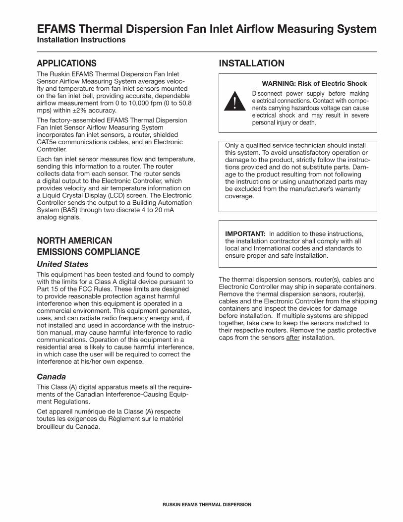
ApplICATIonS The Ruskin EFAMS Thermal Dispersion Fan Inlet Sensor Airflow Measuring System averages veloc-ity and temperature from fan inlet sensors mounted on the fan inlet bell, providing accurate, dependable airflow measurement from 0 to 10,000 fpm (0 to 50.8 mps) within ±2% accuracy.
The factory-assembled EFAMS Thermal Dispersion Fan Inlet Sensor Airflow Measuring System incorporates fan inlet sensors, a router, shielded CAT5e communications cables, and an Electronic Controller.
Each fan inlet sensor measures flow and temperature, sending this information to a router. The router collects data from each sensor. The router sends a digital output to the Electronic Controller, which provides velocity and air temperature information on a Liquid Crystal Display (LCD) screen. The Electronic Controller sends the output to a Building Automation System (BAS) through two discrete 4 to 20 mA analog signals.
norTh AMErICAnEMISSIonS CoMplIAnCE United StatesThis equipment has been tested and found to comply with the limits for a Class A digital device pursuant to Part 15 of the FCC Rules. These limits are designed to provide reasonable protection against harmful interference when this equipment is operated in a commercial environment. This equipment generates, uses, and can radiate radio frequency energy and, if not installed and used in accordance with the instruc-tion manual, may cause harmful interference to radio communications. Operation of this equipment in a residential area is likely to cause harmful interference, in which case the user will be required to correct the interference at his/her own expense.
Only a qualified service technician should install this system. To avoid unsatisfactory operation or damage to the product, strictly follow the instruc-tions provided and do not substitute parts. Dam-age to the product resulting from not following the instructions or using unauthorized parts may be excluded from the manufacturer’s warranty coverage.
EFAMS Thermal Dispersion Fan Inlet Airflow Measuring System Installation Instructions
IMporTAnT: In addition to these instructions, the installation contractor shall comply with all local and International codes and standards to ensure proper and safe installation.
CanadaThis Class (A) digital apparatus meets all the require-ments of the Canadian Interference-Causing Equip-ment Regulations.
Cet appareil numérique de la Classe (A) respecte toutes les exigences du Règlement sur le matériel brouilleur du Canada.
wArnIng: risk of Electric Shock
Disconnect power supply before making electrical connections. Contact with compo-nents carrying hazardous voltage can cause electrical shock and may result in severe personal injury or death.
The thermal dispersion sensors, router(s), cables and Electronic Controller may ship in separate containers. Remove the thermal dispersion sensors, router(s), cables and the Electronic Controller from the shipping containers and inspect the devices for damage before installation. If multiple systems are shipped together, take care to keep the sensors matched to their respective routers. Remove the pastic protective caps from the sensors after installation.
InSTAllATIon
rUSKIn EFAMS ThErMAl DISpErSIon2
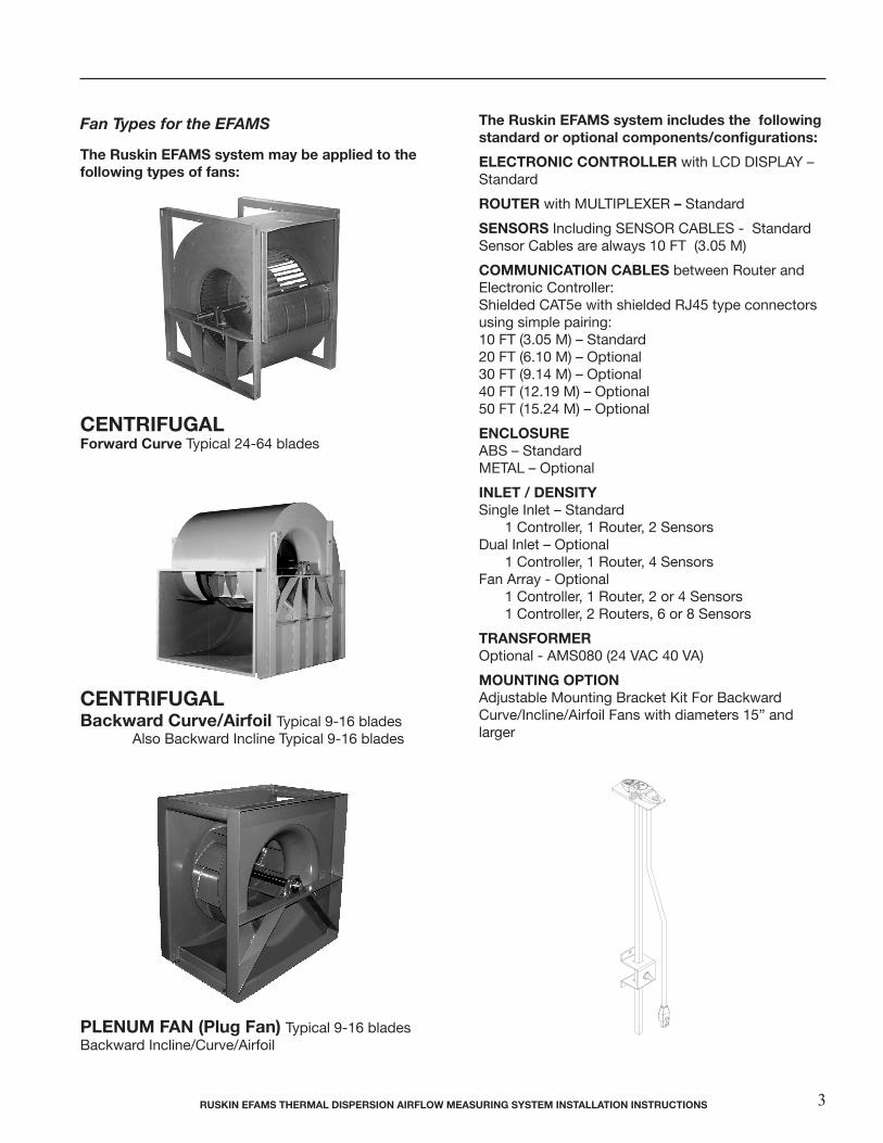
Fan Types for the EFAMS
The ruskin EFAMS system may be applied to the following types of fans:
CEnTrIFUgAl Forward Curve Typical 24-64 blades
CEnTrIFUgAl Backward Curve/Airfoil Typical 9-16 blades Also Backward Incline Typical 9-16 blades
plEnUM FAn (plug Fan) Typical 9-16 bladesBackward Incline/Curve/Airfoil
The ruskin EFAMS system includes the following standard or optional components/configurations:
ElECTronIC ConTrollEr with LCD DISPLAY – Standard
roUTEr with MULTIPLEXER – Standard
SEnSorS Including SENSOR CABLES - Standard Sensor Cables are always 10 FT (3.05 M)
CoMMUnICATIon CABlES between Router and Electronic Controller: Shielded CAT5e with shielded RJ45 type connectors using simple pairing:10 FT (3.05 M) – Standard 20 FT (6.10 M) – Optional 30 FT (9.14 M) – Optional 40 FT (12.19 M) – Optional 50 FT (15.24 M) – Optional
EnCloSUrEABS – Standard METAL – Optional
InlET / DEnSITYSingle Inlet – Standard 1 Controller, 1 Router, 2 Sensors Dual Inlet – Optional 1 Controller, 1 Router, 4 Sensors Fan Array - Optional 1 Controller, 1 Router, 2 or 4 Sensors 1 Controller, 2 Routers, 6 or 8 Sensors
TrAnSForMEr Optional - AMS080 (24 VAC 40 VA)
MoUnTIng opTIonAdjustable Mounting Bracket Kit For Backward Curve/Incline/Airfoil Fans with diameters 15” and larger
rUSKIn EFAMS ThErMAl DISpErSIon AIrFlow MEASUrIng SYSTEM InSTAllATIon InSTrUCTIonS 3
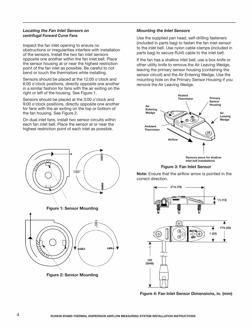
Locating the Fan Inlet Sensors on centrifugal Forward Curve Fans
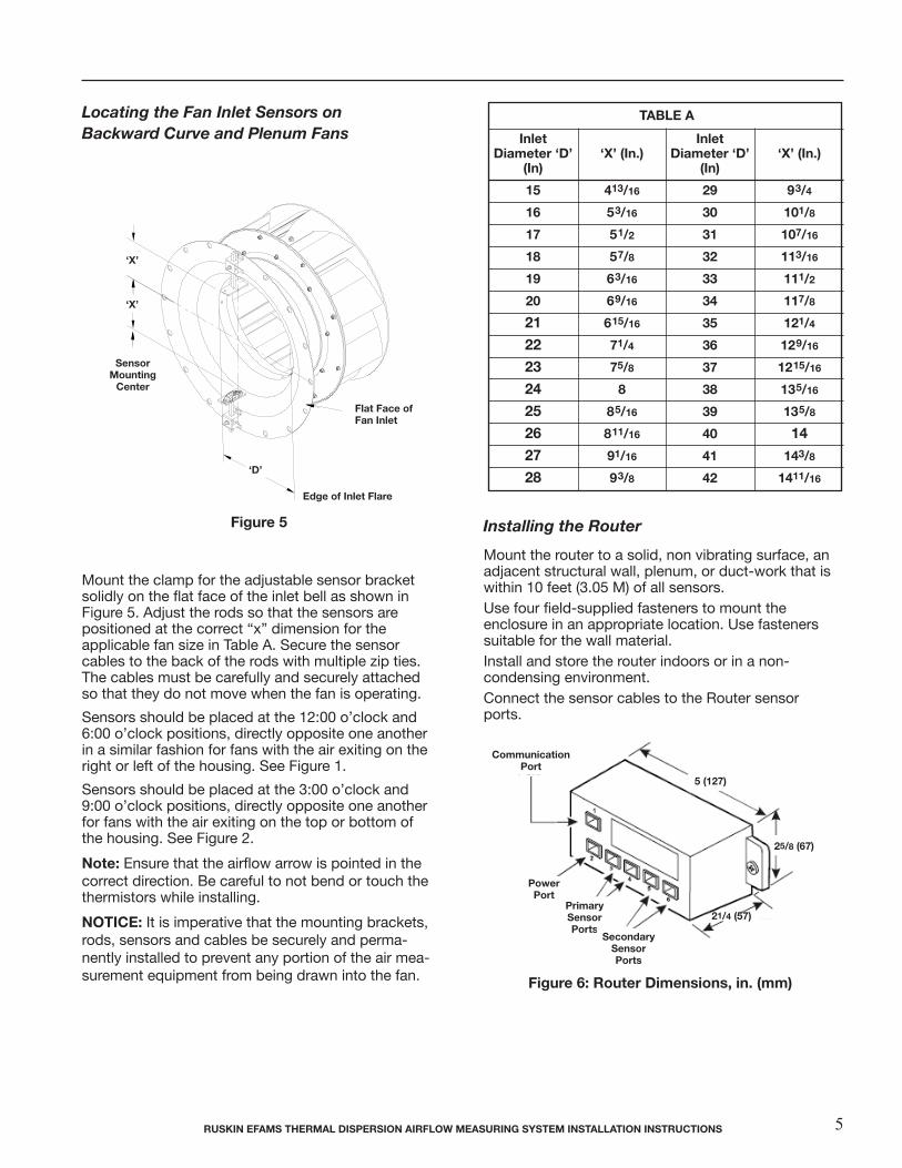
Mounting the Inlet Sensors
Inspect the fan inlet opening to ensure no obstructions or irregularities interfere with installation of the sensors. Install the two fan inlet sensors opposite one another within the fan inlet bell. Place the sensor housing at or near the highest restriction point of the fan inlet as possible. Be careful to not bend or touch the thermistors while installing.
Sensors should be placed at the 12:00 o’clock and 6:00 o’clock positions, directly opposite one another in a similar fashion for fans with the air exiting on the right or left of the housing. See Figure 1.
Sensors should be placed at the 3:00 o’clock and 9:00 o’clock positions, directly opposite one another for fans with the air exiting on the top or bottom of the fan housing. See Figure 2.
On dual inlet fans, install two sensor circuits within each fan inlet bell. Place the sensor at or near the highest restriction point of each inlet as possible.
Use the supplied pan head, self-drilling fasteners(included in parts bag) to fasten the fan inlet sensor to the inlet bell. Use nylon cable clamps (included in parts bag) to secure RJ45 cable to the inlet bell.
If the fan has a shallow inlet bell, use a box knife orother utility knife to remove the Air Leaving Wedge,leaving the primary sensor housing (containing thesensor circuit) and the Air Entering Wedge. Use themounting hole on the Primary Sensor Housing if youremove the Air Leaving Wedge.
Locating the Fan Inlet Sensors on Forward Curve Fans Inspect the fan inlet opening to ensure no obstructions or irregularities interfere with installation of the sensors. Install the two fan inlet sensors opposite one another within the fan inlet bell. Place the sensor housing at or near the highest restriction point of the fan inlet as possible. Sensors should be placed at the 12:00 o'clock and 6:00 o'clock positions, directly opposite one another in a similar fashion for fans with the air exiting on the right or left of the housing. See Figure 1. Sensors should be placed at the 3:00 o'clock and 9:00 o'clock positions, directly opposite one another for fans with the air exiting on the top or bottom of the housing. See Figure 2. On dual inlet fans, install two sensor circuits within each fan inlet bell. Place the sensor housing at or near the highest restriction point of each inlet as possible.
Figure 1: Sensor Mounting
Figure 2: Sensor Mounting
Mounting the Fan Inlet Sensors Use the supplied pan head, self-drilling fasteners (included in parts bag) to fasten the fan inlet sensor to the inlet bell. If the fan has a shallow inlet bell, use a box knife or other utility knife to remove the Air Leaving Wedge, leaving the primary sensor housing (containing the sensor circuit) and the Air Entering Wedge. Use the mounting hole on the Primary Sensor Housing if you remove the Air Leaving Wedge.
Figure 3: Fan Inlet Sensor
Note: Ensure that the airflow arrow is pointed in the correct direction.
Figure 4: Fan Inlet Sensor Dimensions, in. (mm)
RUSKIN EFAMS Thermal Dispersion Airflow Measuring System Installation Instructions
Figure 1: Sensor Mounting
Figure 2: Sensor Mounting
rUSKIn EFAMS ThErMAl DISpErSIon AIrFlow MEASUrIng SYSTEM InSTAllATIon InSTrUCTIonS4
Locating the Fan Inlet Sensors on Forward Curve Fans Inspect the fan inlet opening to ensure no obstructions or irregularities interfere with installation of the sensors. Install the two fan inlet sensors opposite one another within the fan inlet bell. Place the sensor housing at or near the highest restriction point of the fan inlet as possible. Sensors should be placed at the 12:00 o'clock and 6:00 o'clock positions, directly opposite one another in a similar fashion for fans with the air exiting on the right or left of the housing. See Figure 1. Sensors should be placed at the 3:00 o'clock and 9:00 o'clock positions, directly opposite one another for fans with the air exiting on the top or bottom of the housing. See Figure 2. On dual inlet fans, install two sensor circuits within each fan inlet bell. Place the sensor housing at or near the highest restriction point of each inlet as possible.
Figure 1: Sensor Mounting
Figure 2: Sensor Mounting
Mounting the Fan Inlet Sensors Use the supplied pan head, self-drilling fasteners (included in parts bag) to fasten the fan inlet sensor to the inlet bell. If the fan has a shallow inlet bell, use a box knife or other utility knife to remove the Air Leaving Wedge, leaving the primary sensor housing (containing the sensor circuit) and the Air Entering Wedge. Use the mounting hole on the Primary Sensor Housing if you remove the Air Leaving Wedge.
Figure 3: Fan Inlet Sensor
Note: Ensure that the airflow arrow is pointed in the correct direction.
Figure 4: Fan Inlet Sensor Dimensions, in. (mm)
RUSKIN EFAMS Thermal Dispersion Airflow Measuring System Installation Instructions
Figure 3: Fan Inlet Sensor
note: Ensure that the airflow arrow is pointed in the correct direction.
Figure 4: Fan Inlet Sensor Dimensions, in. (mm)
120(3048)
13/8 (35)
1 (25)
31/8 (79)
1/2 (13)
Airflow
primarySensorhousing
Airleaving wedge
AirEntering wedge
AmbientThermistor
heatedThermistor
remove piece for shallowinlet bell installations
‘X’ (In.)
93/4
101/8
107/16
113/16
111/2
117/8
121/4
129/16
1215/16
135/16
135/8
14
143/8
1411/16
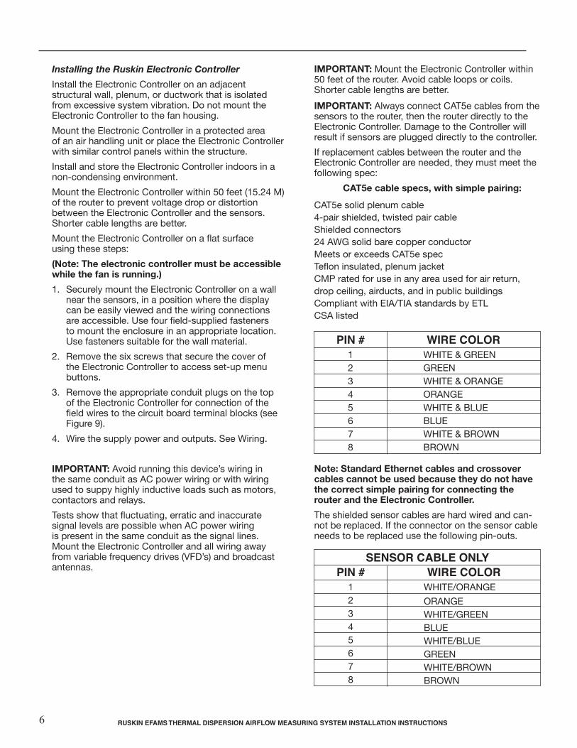
Locating the Fan Inlet Sensors onBackward Curve and Plenum Fans
Locating the Fan Inlet Sensors on Plenum Fans
Figure 5
Mount the rods solidly on the flat face of the inlet bell as shown in Figure 5. Adjust the rods so that the sensors are positioned at the correct “x” dimension for the applicable fan size in Table A. Secure the sensor cables to the back of the rods with zip ties. The cables must be carefully and securely attached so that they do not move when the fan is running.
Table A
Installing the Router Do not mount the router to the fan housing. Install the router on an adjacent structural wall, plenum, or duct-work that is isolated from excessive system vibration. Securely mount the router on a wall near the sensors. Use four field-supplied fasteners to mount the enclosure in an appropriate location. Use fasteners suitable for the wall material. Do not install or store the router outdoors.
Figure 6
Inlet Diameter 'D'
(in) X' (in.)
Inlet Diameter 'D'
(in) X' (in.)
15 4 13/16 29 9 3/4
16 5 3/16 30 10 1/8
17 5 1/2 31 10 7/16
18 5 7/8 32 11 3/16
19 6 3/16 33 11 1/2
20 6 9/16 34 11 7/8
21 6 15/16 35 12 1/4
22 7 1/4 36 12 9/16
23 7 5/8 37 12 15/16
24 8 38 13 5/16
25 8 5/16 39 13 5/8
26 8 11/16 40 14
27 9 1/16 41 14 3/8
28 9 3/8 42 14 11/16
RUSKIN EFAMS Thermal Dispersion Airflow Measuring System Installation Instructions
Figure 5
Mount the clamp for the adjustable sensor bracket solidly on the flat face of the inlet bell as shown in Figure 5. Adjust the rods so that the sensors are positioned at the correct “x” dimension for the applicable fan size in Table A. Secure the sensor cables to the back of the rods with multiple zip ties. The cables must be carefully and securely attached so that they do not move when the fan is operating.
Sensors should be placed at the 12:00 o’clock and 6:00 o’clock positions, directly opposite one another in a similar fashion for fans with the air exiting on the right or left of the housing. See Figure 1.
Sensors should be placed at the 3:00 o’clock and 9:00 o’clock positions, directly opposite one another for fans with the air exiting on the top or bottom of the housing. See Figure 2.
note: Ensure that the airflow arrow is pointed in the correct direction. Be careful to not bend or touch the thermis tors while installing.
noTICE: It is imperative that the mounting brackets, rods, sensors and cables be securely and perma-nently installed to prevent any portion of the air mea-surement equipment from being drawn into the fan.
Mount the router to a solid, non vibrating surface, an adjacent structural wall, plenum, or duct-work that is within 10 feet (3.05 M) of all sensors.Use four field-supplied fasteners to mount theenclosure in an appropriate location. Use fastenerssuitable for the wall material. Install and store the router indoors or in a non-condensing environment.Connect the sensor cables to the Router sensor ports.
Installing the Router
Figure 6: router Dimensions, in. (mm)
Communicationport
25/8 (67)
5 (127)
powerport
primarySensor ports
SecondarySensorports
21/4 (57)
InletDiameter ‘D’
(In)
15
16
17
18
19
20
21
22
23
24
25
26
27
28
‘X’ (In.)
413/16
53/16
51/2
57/8
63/16
69/16
615/16
71/4
75/8
8
85/16
811/16
91/16
93/8
InletDiameter ‘D’
(In)
29
30
31
32
33
34
35
36
37
38
39
40
41
42
‘X’
‘X’
‘D’
Edge of Inlet Flare
Flat Face ofFan Inlet
SensorMounting
Center
TABlE A
rUSKIn EFAMS ThErMAl DISpErSIon AIrFlow MEASUrIng SYSTEM InSTAllATIon InSTrUCTIonS 5
Installing the Ruskin Electronic Controller
Install the Electronic Controller on an adjacent structural wall, plenum, or ductwork that is isolated from excessive system vibration. Do not mount the Electronic Controller to the fan housing.
Mount the Electronic Controller in a protected area of an air handling unit or place the Electronic Controller with similar control panels within the structure.
Install and store the Electronic Controller indoors in a non-condensing environment.
Mount the Electronic Controller within 50 feet (15.24 M) of the router to prevent voltage drop or distortion between the Electronic Controller and the sensors. Shorter cable lengths are better.
Mount the Electronic Controller on a flat surface using these steps:
(note: The electronic controller must be accessible while the fan is running.)
1. Securely mount the Electronic Controller on a wall near the sensors, in a position where the display can be easily viewed and the wiring connections are accessible. Use four field-supplied fasteners to mount the enclosure in an appropriate location. Use fasteners suitable for the wall material.
2. Remove the six screws that secure the cover of the Electronic Controller to access set-up menu buttons.
3. Remove the appropriate conduit plugs on the top of the Electronic Controller for connection of the field wires to the circuit board terminal blocks (see Figure 9).
4. Wire the supply power and outputs. See Wiring.
IMporTAnT: Avoid running this device’s wiring in the same conduit as AC power wiring or with wiring used to suppy highly inductive loads such as motors, contactors and relays.
Tests show that fluctuating, erratic and inaccurate signal levels are possible when AC power wiring is present in the same conduit as the signal lines. Mount the Electronic Controller and all wiring away from variable frequency drives (VFD’s) and broadcast antennas.
IMporTAnT: Mount the Electronic Controller within 50 feet of the router. Avoid cable loops or coils. Shorter cable lengths are better.
IMporTAnT: Always connect CAT5e cables from the sensors to the router, then the router directly to the Electronic Controller. Damage to the Controller will result if sensors are plugged directly to the controller.
If replacement cables between the router and the Electronic Controller are needed, they must meet the following spec:
CAT5e cable specs, with simple pairing:
CAT5e solid plenum cable 4-pair shielded, twisted pair cable Shielded connectors 24 AWG solid bare copper conductor Meets or exceeds CAT5e spec Teflon insulated, plenum jacket CMP rated for use in any area used for air return, drop ceiling, airducts, and in public buildings Compliant with EIA/TIA standards by ETL CSA listed
note: Standard Ethernet cables and crossover cables cannot be used because they do not have the correct simple pairing for connecting the router and the Electronic Controller.
The shielded sensor cables are hard wired and can- not be replaced. If the connector on the sensor cable needs to be replaced use the following pin-outs.
rUSKIn EFAMS ThErMAl DISpErSIon AIrFlow MEASUrIng SYSTEM InSTAllATIon InSTrUCTIonS 7
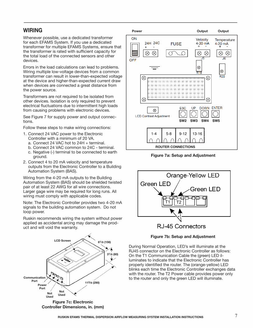
wIrIng Whenever possible, use a dedicated transformer for each EFAMS System. If you use a dedicated transformer for multiple EFAMS Systems, ensure that the transformer is rated with sufficient capacity for the total load of the connected sensors and other devices.
Errors in the load calculations can lead to problems. Wiring multiple low-voltage devices from a common transformer can result in lower-than-expected voltage at the device and higher-than-expected current draw when devices are connected a great distance from the power source.
Transformers are not required to be isolated from other devices. Isolation is only required to prevent electrical fluctuations due to intermittent high loads from causing problems with electronic devices.
See Figure 7 for supply power and output connec-tions.
Follow these steps to make wiring connections:
1. Connect 24 VAC power to the Electronic Controller with a minimum of 20 VA. a. Connect 24 VAC hot to 24H + terminal. b. Connect 24 VAC common to 24C - terminal. c. Negative (-) terminal to be connected to earth ground.2. Connect 4 to 20 mA velocity and temperature outputs from the Electronic Controller to a Building Automation System (BAS).
Wiring from the 4-20 mA outputs to the Building Automation System (BAS) should be shielded twisted pair of at least 22 AWG for all wire connections. Larger gage wire may be required for long runs. All wiring must comply with applicable codes.
Note: The Electronic Controller provides two 4-20 mA signals to the building automation system. Do not loop power.
Ruskin recommends wiring the system without power applied as accidental arcing may damage the prod-uct and will void the warranty.
Figure 7a: Setup and Adjustment
Figure 7b: Setup and Adjustment
roUTEr ConnECTIonS
During Normal Operation, LED’s will illuminate at the RJ45 connector on the Electronic Controller as follows: On the T1 Communication Cable the (green) LED il-luminates to indicate that the Electronic Controller has properly identified the router. The (orange-yellow) LED blinks each time the Electronic Controller exchanges data with the router. The T2 Power cable provides power only to the router and only the green LED will illuminate.
output outputpower
SW2 SW3 SW4 SW5
1-4 5-8 9-12 13-16
T1 T2
Finishing the Installation
1. Connect a shielded CAT5e cable between the Communication Port RJ45 connector on the router (see Figure 7 and Figure 8) to the Communication Port RJ45 connector on the Electronic Controller (see Figure 7 and Figure 8) .
2. Connect a shielded CAT5e cable between the Power Port RJ45 connector on the router (see Figure 7 and Figure 8) to the Power Port RJ45 connector on the Electronic Controller (see Figure 7 and Figure 8).
3. Use nylon cable clamps (included in parts bag) to secure RJ45 cable between the sensors and the router, and between the router and the Electronic Controler. Space cable clamps on 6 in. (152 mm) centers. 4. Move the Electronic Controller’s power switch (see Figure 9) to the ON position. 5. Use the LCD Contrast Adjustment screw (see Figure 9) to adjust the LCD contrast as desired: • Turn the screw clockwise to increase contrast. • Turn the screw counterclockwise to decrease contrast. 6. Use the Options Menu to configure the Electronic Controller for your application. See Setup and Adjustments for specific instructions. 7. After configuring the Electronic Controller, replace the cover.
RUSKIN EFAMS Thermal Dispersion Airflow Measuring System Installation Instructions
powerport
Communicationport
notUsed
notUsed
lCD Screen 61/8 (156)
31/8 (80)
113/8 (290)
Figure 7c: ElectronicController Dimensions, in. (mm)
rUSKIn EFAMS ThErMAl DISpErSIon AIrFlow MEASUrIng SYSTEM InSTAllATIon InSTrUCTIonS8
Finishing the Installation
Finishing the Installation
1. Connect a shielded CAT5e cable between the Communication Port RJ45 connector on the router (see Figure 7 and Figure 8) to the Communication Port RJ45 connector on the Electronic Controller (see Figure 7 and Figure 8) .
2. Connect a shielded CAT5e cable between the Power Port RJ45 connector on the router (see Figure 7 and Figure 8) to the Power Port RJ45 connector on the Electronic Controller (see Figure 7 and Figure 8).
3. Use nylon cable clamps (included in parts bag) to secure RJ45 cable between the sensors and the router, and between the router and the Electronic Controler. Space cable clamps on 6 in. (152 mm) centers. 4. Move the Electronic Controller’s power switch (see Figure 9) to the ON position. 5. Use the LCD Contrast Adjustment screw (see Figure 9) to adjust the LCD contrast as desired: • Turn the screw clockwise to increase contrast. • Turn the screw counterclockwise to decrease contrast. 6. Use the Options Menu to configure the Electronic Controller for your application. See Setup and Adjustments for specific instructions. 7. After configuring the Electronic Controller, replace the cover.
RUSKIN EFAMS Thermal Dispersion Airflow Measuring System Installation Instructions
powerport
router
Fan InletSensors
Communicationport
CommunicationCable
Electronic Controller
Communication port
power port
powerCable
Sensor Cables
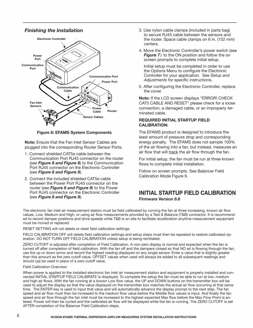
Figure 8: EFAMS System Components
note: Ensure that the Fan Inlet Sensor Cables are plugged into the corresponding Router Sensor Ports.
1. Connect shielded CAT5e cable between the Communication Port RJ45 connector on the router (see Figure 8 and Figure 9) to the Communication Port RJ45 connector on the Electronic Controller (see Figure 8 and Figure 9).
2. Connect the included shielded CAT5e cable between the Power Port RJ45 connector on the router (see Figure 8 and Figure 9) to the Power Port RJ45 connector on the Electronic Controller (see Figure 8 and Figure 9).
3. Use nylon cable clamps (included in parts bag) to secure RJ45 cable between the sensors and the router. Space cable clamps on 6 in. (152 mm) centers.
4. Move the Electronic Controller’s power switch (see Figure 7 ) to the ON position and follow the on screen prompts to complete initial setup.
Initial setup must be completed in order to use the Options Menu to configure the Electronic Controller for your application. See Setup and Adjustments for specific instructions.
5. After configuring the Electronic Controller, replace the cover.
note: If the LCD screen displays “ERROR! CHECK CAT5 CABLE AND RESET” please check for a loose connection, a damaged cable, or an improperly ter-minated cable.
rEQUIrED InITIAl STArTUp FIElD CAlIBrATIon:
The EFAMS product is designed to introduce the least amount of pressure drop and corresponding energy penalty. The EFAMS does not sample 100% of the air flowing into a fan, but instead, measures an air flow that will track the air flow through the fan.
For initial setup, the fan must be run at three known flows to complete initial installation.
Follow on screen prompts. See Balancer Field Calibration Mode Figure 9.
InITIAl STArTUp FIElD CAlIBrATIonFirmware Version 8.6
The electronic fan inlet air measurement station must be field calibrated by running the fan at three increasing, known air flow values, Low, Medium and High, or using air flow measurements provided by a Test & Balance (T&B) contractor. It is recommend-ed to record damper positions and drive speeds while T&B is on site to facilitate recalibration anytime measurement equipment must be moved or replaced.
RESET SETTING will not delete or reset field calibration settings.
FIELD CALIBRATION OFF will delete field calibration settings and setup steps must then be repeated to restore calibrated op-eration. DO NOT TURN OFF FIELD CALIBRATION unless setup is being reinitiated.
ZERO CUTOFF is adjusted after completion of Field Calibration. A non-zero display is normal and expected when the fan is turned off after completion of field calibration. With the fan off and the dampers closed so that NO air is flowing through the fan, use the up or down arrow and record the highest reading displayed on any single sensor. Enter a value that is slightly greater than this amount as the zero cutoff value. OFFSET values when used will always be added to all subsequent readings and should not be used in place of a zero cutoff value.
Field Calibration Overview:
When power is applied to the installed electronic fan inlet air measurement station and equipment is properly installed and con-nected INITIAL STARTUP FIELD CALIBRATE is displayed. To complete the setup the fan must be able to run at low, medium and high air flows. With the fan running at a known Low flow value, the UP and DOWN buttons on the transmitter box will be used to adjust the display so that the value displayed on the transmitter box matches the actual air flow occurring at that same time. The ENTER key is used to input that value and will automatically advance the display prompt to the next step. The fan speed and air flow must then be increased to the medium flow value before the Middle flow values is input. And finally the fan speed and air flow through the fan inlet must be increased to the highest expected Max flow before the Max Flow Point is en-tered. Power will then be cycled and the calibrated air flow will be displayed while the fan is running. The ZERO CUTOFF is set AFTER completion of the Balancer Field Calibration steps.
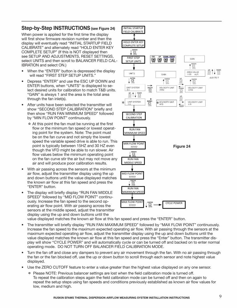
Step-by-Step InSTrUCTIonS (see Figure 24)
When power is applied for the first time the display will first show firmware revision number and then the display will eventually read “INITIAL STARTUP FIELD CALIBRATE” and alternately read “HOLD ENTER KEY COMPLETE SETUP” (If this is NOT displayed then see SETUP AND ADJUSTMENTS, RESET SETTINGS, select UNITS and then scroll to BALANCER FIELD CAL-IBRATION and select ON.)
• When the “ENTER” button is depressed the display will read “FIRST STEP SETUP UNITS.”
• Depress “ENTER” and use the ESC UP DOWN and ENTER buttons, when “UNITS” is displayed to se-lect desired units for calibration to match T&B units. “GAIN” is always 1 and the area is the total area through the fan inlet(s).
• After units have been selected the transmitter will show “SECOND STEP CALIBRATION” briefly and then show “RUN FAN MINIMUM SPEED” followed by “MIN FLOW POINT” continuously.
At this point the fan must be running at the first flow or the minimum fan speed or lowest operat-ing point for the system. Note: The point must be on the fan curve and not simply the lowest speed the variable speed drive is able to run. This point is typically between 15HZ and 30 HZ even though the VFD might be able to run slower. Air flow values below the minimum operating point on the fan curve stir the air but may not move any air and will produce poor calibration results.
• With air passing across the sensors at the minimum air flow, adjust the transmitter display using the up and down buttons until the value displayed matches the known air flow at this fan speed and press the “ENTER” button.
• The display will briefly display “RUN FAN MIDDLE SPEED” followed by “MID FLOW POINT” continu-ously. Increase the fan speed to the second op-erating air flow point. With air passing across the sensors at the middle speed, adjust the transmitter display using the up and down buttons until the value displayed matches the known air flow at this fan speed and press the “ENTER” button.
• The transmitter will briefly display “RUN FAN MAXIMUM SPEED” followed by “MAX FLOW POINT” continuously. Increase the fan speed to the maximum expected operating air flow. With air passing through the sensors at the maximum expected operating air flow, adjust the transmitter display using the up and down buttons until the value displayed matches the known air flow at this fan speed and press the “Enter” button. The transmitter dis-play will show “CYCLE POWER” and will automatically cycle or can be turned off and backed on to enter normal operating mode. DO NOT TURN OFF BALANCER FIELD CALIBRATION MODE.
• Turn the fan off and close any dampers to prevent any air movement through the fan. With no air passing through the fan or the fan blocked off, use the up or down button to scroll through each sensor and note highest value displayed.
• Use the ZERO CUTOFF feature to enter a value greater than the highest value displayed on any one sensor.
Please NOTE: Previous balancer settings are lost when the field calibration mode is turned off. To repeat the calibration steps again the field calibration mode can be turned off and then on again to repeat the setup steps using fan speeds and conditions previously established as known air flow values for low, medium and high.
INITIAL STARTUPFIELD CALIBRATE
HOLD ENTER KEYCOMPLETE SETUP
FIRST STEPSETUP UNITS
SECOND STEPCALIBRATION
RUN FANMINIMUM SPEED
MIN FLOW POINT?????
MID FLOW POINT?????
RUN FANMIDDLE SPEED
MAX FLOW POINT?????
RUN FANMAXIMUM SPEED
CYCLE POWER
rUSKIn EFAMS ThErMAl DISpErSIon AIrFlow MEASUrIng SYSTEM InSTAllATIon InSTrUCTIonS 9
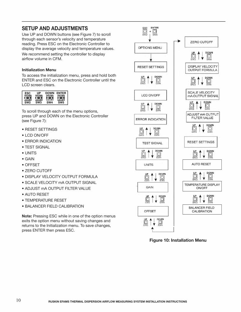
Figure 10: Installation Menu
SETUp AnD ADjUSTMEnTS Use UP and DOWN buttons (see Figure 7) to scroll through each sensor’s velocity and temperature reading. Press ESC on the Electronic Controller to display the average velocity and temperature values.We recommend setting the controller to display airflow volume in CFM.
Initialization MenuTo access the initialization menu, press and hold both ENTER and ESC on the Electronic Controller until the LCD screen clears.
To scroll through each of the menu options, press UP and DOWN on the Electronic Controller (see Figure 7):
• RESET SETTINGS
• LCD ON/OFF
• ERROR INDICATION
• TEST SIGNAL
• UNITS
• GAIN
• OFFSET
• ZERO CUTOFF
• DISPLAY VELOCITY OUTPUT FORMULA
• SCALE VELOCITY mA OUTPUT SIGNAL
• ADJUST mA OUTPUT FILTER VALUE
• AUTO RESET
• TEMPERATURE RESET
• BALANCER FIELD CALIBRATION note: Pressing ESC while in one of the option menus exits the option menu without saving changes and returns to the Initialization menu. To save changes, press ENTER then press ESC.
ESC UP DOWN ENTER
SW2 SW3 SW4 SW5
rUSKIn EFAMS ThErMAl DISpErSIon AIrFlow MEASUrIng SYSTEM InSTAllATIon InSTrUCTIonS10

rESET SETTIngSThis option restores the Electronic Controller to the default factory settings.
lCD on/oFFThis option turns the LCD screen on the Electronic Controller ON or OFF. note: Pressing ESC, UP, DOWN, or ENTER reacti-vates the LCD screen.
Figure 12: lCD on/oFF Submenu
Figure 13: Error Indication Submenu
Error InDICATIonThis option activates the error indication on the LCD screen. When an error occurs, the temperature ap-pears as a lowercase letter f (degrees Fahrenheit).
note: If the Electronic Controller has settings other than the default settings, you may want to make note of them before you reset the Electronic Con-troller. The default values are denoted in Figures 11 through 21 with an asterisk *.
Figure 11 ARE YOU SURE
Figure 12 DISPLAY
Figure 13 ERROR INDICATION
Figure 14 SET TEST SIGNAL
Figure 15 UNIT SYSTEM, VELOCITY UNIT
Figure 16 GAIN VALUE
Figure 17 OFFSET VALUE
Figure 18 CUTOFF VALUE
Figure 19 DISPLAY VELOCITY OUTPUT FORMULA
Figure 20 SCALE VELOCITY mA OUTPUT SIGNAL
Figure 21 FILTER VALUE
Figure 22 AUTO RESET
Figure 23 TEMPERATURE RESET
Figure 24 BALANCER FIELD CALIBRATION
Figure 11: reset Settings Submenu
*
rUSKIn EFAMS ThErMAl DISpErSIon AIrFlow MEASUrIng SYSTEM InSTAllATIon InSTrUCTIonS 11
ESC UP DOWN ENTER
SW2 SW3 SW4 SW5
*
ESC UP DOWN ENTER
SW2 SW3 SW4 SW5
*
ESC UP DOWN ENTER
SW2 SW3 SW4 SW5
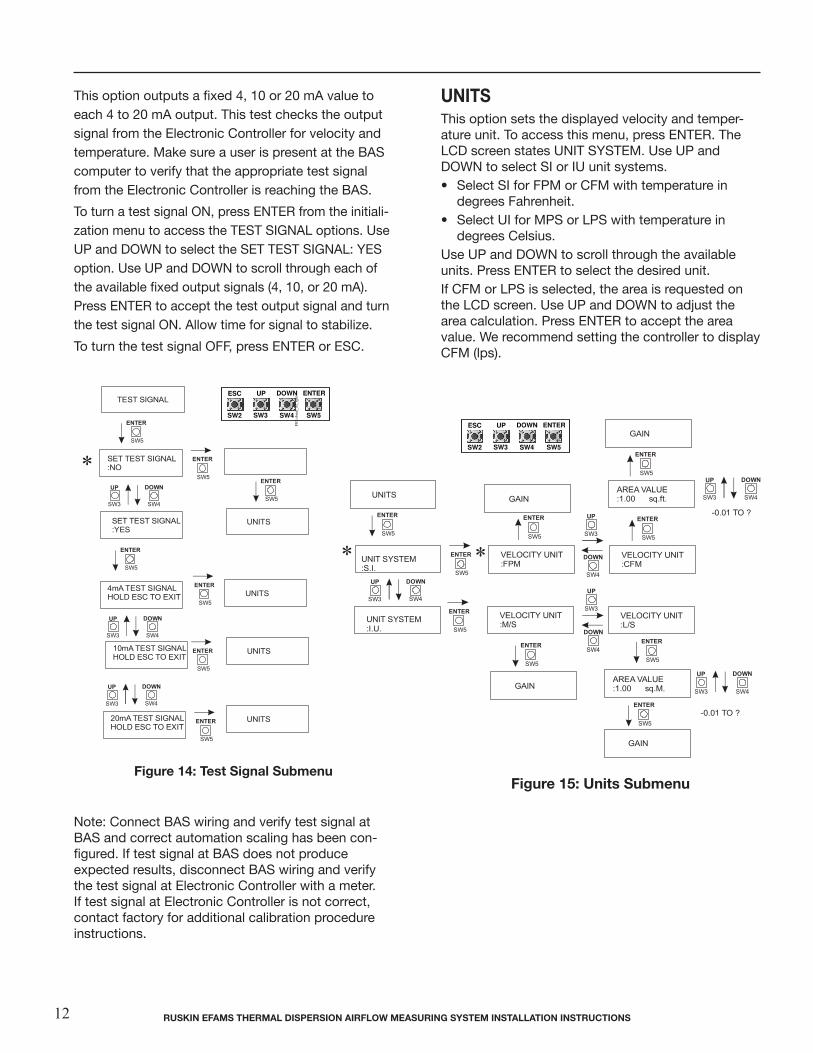
This option outputs a fixed 4, 10 or 20 mA value to each 4 to 20 mA output. This test checks the output signal from the Electronic Controller for velocity and temperature. Make sure a user is present at the BAS computer to verify that the appropriate test signal from the Electronic Controller is reaching the BAS.
To turn a test signal ON, press ENTER from the initiali-zation menu to access the TEST SIGNAL options. Use UP and DOWN to select the SET TEST SIGNAL: YES option. Use UP and DOWN to scroll through each of the available fixed output signals (4, 10, or 20 mA). Press ENTER to accept the test output signal and turn the test signal ON. Allow time for signal to stabilize.
To turn the test signal OFF, press ENTER or ESC.
UnITS This option sets the displayed velocity and temper-ature unit. To access this menu, press ENTER. The LCD screen states UNIT SYSTEM. Use UP and DOWN to select SI or IU unit systems. • Select SI for FPM or CFM with temperature in degrees Fahrenheit. • Select UI for MPS or LPS with temperature in degrees Celsius. Use UP and DOWN to scroll through the available units. Press ENTER to select the desired unit. If CFM or LPS is selected, the area is requested on the LCD screen. Use UP and DOWN to adjust the area calculation. Press ENTER to accept the area value. We recommend setting the controller to display CFM (lps).
Note: Connect BAS wiring and verify test signal at BAS and correct automation scaling has been con-figured. If test signal at BAS does not produceexpected results, disconnect BAS wiring and verify the test signal at Electronic Controller with a meter. If test signal at Electronic Controller is not correct, contact factory for additional calibration procedure instructions.
Figure 14: Test Signal SubmenuFigure 15: Units Submenu
* *
ESC UP DOWN ENTER
SW2 SW3 SW4 SW5
*
ESC UP DOWN ENTER
SW2 SW3 SW4 SW5
rUSKIn EFAMS ThErMAl DISpErSIon AIrFlow MEASUrIng SYSTEM InSTAllATIon InSTrUCTIonS12
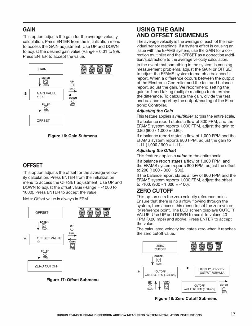
gAIn This option adjusts the gain for the average velocity calculation. Press ENTER from the initialization menu to access the GAIN adjustment. Use UP and DOWN to adjust the desired gain value (Range = 0.01 to 99). Press ENTER to accept the value.
oFFSET This option adjusts the offset for the average veloc-ity calculation. Press ENTER from the initialization menu to access the OFFSET adjustment. Use UP and DOWN to adjust the offset value (Range = -1000 to 1000). Press ENTER to accept the value.
Note: Offset value is always in FPM.
Figure 16: gain Submenu
Figure 18: Zero Cutoff Submenu
Figure 17: offset Submenu
*
*
ESC UP DOWN ENTER
SW2 SW3 SW4 SW5
ESC UP DOWN ENTER
SW2 SW3 SW4 SW5
rUSKIn EFAMS ThErMAl DISpErSIon AIrFlow MEASUrIng SYSTEM InSTAllATIon InSTrUCTIonS 13
USIng ThE gAInAnD oFFSET SUBMEnUS The average velocity is the average of each of the indi-vidual sensor readings. If a system effect is causing an issue with the EFAMS system, use the GAIN for a cor-rection multiplier and the OFFSET as a correction (addi-tion/subtraction) to the average velocity calculation.In the event that something in the system is causing measurement problems, adjust the GAIN or OFFSET to adjust the EFAMS system to match a balancer’s report. When a difference occurs between the output of the Electronic Controller and the test and balance report, adjust the gain. We recommend setting the gain to 1 and taking multiple readings to determine the difference. To calculate the gain, divide the test and balance report by the output/reading of the Elec-tronic Controller.Adjusting the Gain This feature applies a multiplier across the entire scale.If a balance report states a flow of 800 FPM, and the EFAMS system reports 1,000 FPM, adjust the gain to 0.80 (800 / 1,000 = 0.80). If a balance report states a flow of 1,000 FPM and the EFAMS system reports 900 FPM, adjust the gain to 1.11 (1,000 / 900 = 1.11). Adjusting the Offset This feature applies a value to the entire scale.If a balance report states a flow of 1,000 FPM, and the EFAMS system reports 800 FPM, adjust the offset to 200 (1000 - 800 = 200). If the balance report states a flow of 900 FPM and the EFAMS system reports 1,000 FPM, adjust the offset to -100. (900 - 1,000 = -100).
ZEro CUToFF This option sets the zero velocity reference point. Ensure that there is no airflow flowing through the system, then access this menu to set the zero veloc-ity reference point. The LCD screen displays CUTOFF VALUE. Use UP and DOWN to scroll to values 40 FPM (0.20 mps) and above. Press ENTER to accept the value. The calculated velocity indicates zero when it reaches the zero cutoff value.
CUTOFFVALUE: 40 FPM (0.20 mps)
ZEROCUTOFF
DISPLAY VELOCITYOUTPUT FORMULA*
ESC UP DOWN ENTER
SW2 SW3 SW4 SW5
CUTOFFVALUE: 65 FPM (0.33 mps)
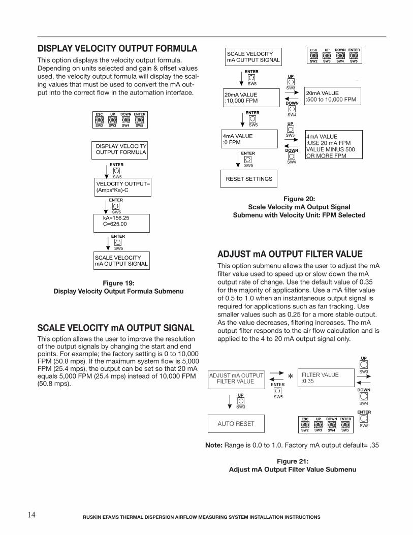
DISplAY VEloCITY oUTpUT ForMUlA This option displays the velocity output formula. Depending on units selected and gain & offset values used, the velocity output formula will display the scal-ing values that must be used to convert the mA out-put into the correct flow in the automation interface.
ADjUST mA oUTpUT FIlTEr VAlUEThis option submenu allows the user to adjust the mA filter value used to speed up or slow down the mA output rate of change. Use the default value of 0.35 for the majority of applications. Use a mA filter value of 0.5 to 1.0 when an instantaneous output signal is required for applications such as fan tracking. Use smaller values such as 0.25 for a more stable output. As the value decreases, filtering increases. The mA output filter responds to the air flow calculation and is applied to the 4 to 20 mA output signal only.
SCAlE VEloCITY mA oUTpUT SIgnAlThis option allows the user to improve the resolution of the output signals by changing the start and end points. For example; the factory setting is 0 to 10,000 FPM (50.8 mps). If the maximum system flow is 5,000 FPM (25.4 mps), the output can be set so that 20 mA equals 5,000 FPM (25.4 mps) instead of 10,000 FPM (50.8 mps).
Figure 19:Display Velocity output Formula Submenu
Figure 20:Scale Velocity mA output Signal
Submenu with Velocity Unit: FpM Selected
note: Range is 0.0 to 1.0. Factory mA output default= .35
Figure 21:Adjust mA output Filter Value Submenu
*
Up
SW3
EnTEr
SW5
Down
SW4
ESC UP DOWN ENTER
SW2 SW3 SW4 SW5
ESC UP DOWN ENTER
SW2 SW3 SW4 SW5
UP
SW3
ESC
SW2
EntEr
SW5
down
SW4
:500 to 10,000 FPM
4mA VALUE:USE 20 mA FPM VALUE MINUS 500 OR MORE FPM
ESC UP DOWN ENTER
SW2 SW3 SW4 SW5
:10,000 FPM
AUTO RESET
rUSKIn EFAMS ThErMAl DISpErSIon AIrFlow MEASUrIng SYSTEM InSTAllATIon InSTrUCTIonS14
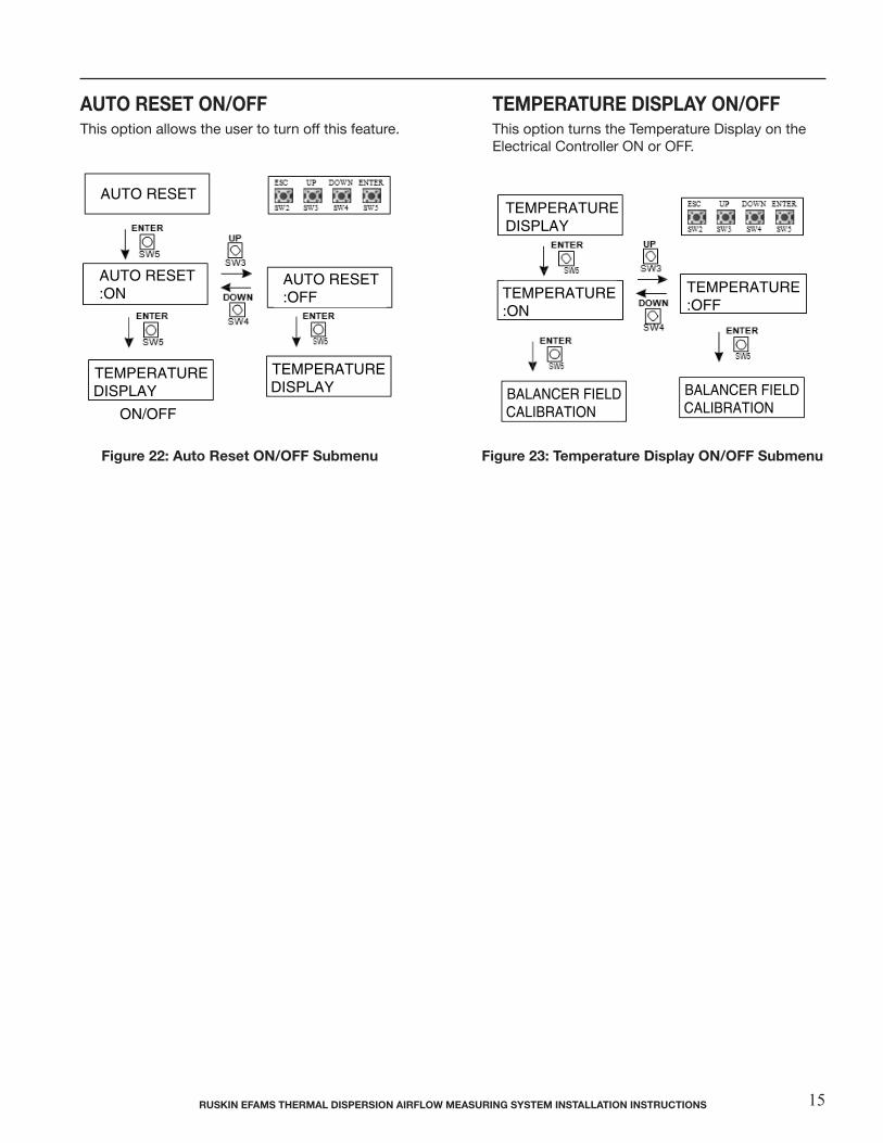
AUTo rESET on/oFFThis option allows the user to turn off this feature.
TEMpErATUrE DISplAY on/oFF This option turns the Temperature Display on the Electrical Controller ON or OFF.
rUSKIn EFAMS ThErMAl DISpErSIon AIrFlow MEASUrIng SYSTEM InSTAllATIon InSTrUCTIonS 15
AUTO RESET
TEMPERATURE DISPLAY ON/OFF
TEMPERATURE DISPLAY ON/OFF
TEMPERATURE DISPLAY
ON/OFF
BALANCER FIELD CALIBRATION
BALANCER FIELD CALIBRATION
AUTO RESET ON/OFF This option allows the user to turn off this feature.
TEMPERATURE DISPLAY ON/OFF This option turns the Temperature Display on the Electronic Controller ON or OFF.
AUTO RESET:ON
AUTO RESET:OFF
TEMPERATURE:ON
TEMPERATURE:OFF
Figure 23: Temperature Display ON/OFF Submenu
Figure 22: Auto Reset ON/OFF Submenu
Figure 22: Auto reset on/oFF Submenu Figure 23: Temperature Display on/oFF Submenu
AUTO RESET
TEMPERATURE DISPLAY ON/OFF
TEMPERATURE DISPLAY ON/OFF
TEMPERATURE DISPLAY
ON/OFF
BALANCER FIELD CALIBRATION
BALANCER FIELD CALIBRATION
AUTO RESET ON/OFF This option allows the user to turn off this feature.
TEMPERATURE DISPLAY ON/OFF This option turns the Temperature Display on the Electronic Controller ON or OFF.
AUTO RESET:ON
AUTO RESET:OFF
TEMPERATURE:ON
TEMPERATURE:OFF
Figure 23: Temperature Display ON/OFF Submenu
Figure 22: Auto Reset ON/OFF Submenu

During Normal Operation LEDs illuminate at the RJ45 connector on the Electronic Controller. The left (green) LED indicates that the Electronic Controller has properly identified the router. The right (orange-yellow) LED illuminates each time the Electronic Controller communicates with the router. See Figure 7b. If the right (orange-yellow) LED does not blink, reset the Elec-tronic Controller by cycling the power switch OFF and then ON. See Figure 7. Use UP and DOWN (see Figure 7) to scroll through each sensor’s velocity and temperature reading. Press ESC on the Electronic Controller to display the average velocity and temperature values.If an error occurs with one of the sensors, an error indication displays on the LCD screen. The error is indicated on the LCD screen by the velocity unit in lowercase letters.
rEpAIr InForMATIon If the EFAMS Thermal Dispersion Fan Inlet Measuring System fails to operate within its specifications, replace the unit. For a replacement EFAMS System, contact the nearest Ruskin repre-sentative.
MAInTEnAnCE Once a year, scroll through the velocity and temperature values using UP and DOWN (see Figure 7). Clean the sensor nodes if readings vary from normal readings.
To clean the electronic sensors: 1. Remove cover from Electronic Controller and turn power switch off. Please make sure the sensor is allowed to cool before cleaning.2. Unplug the shielded Cat5e cable from the RJ45 connector on the end of the thermal dispersion sensor. 3. Spray the thermal dispersion sensor with a non-flammmable circuit board cleaner if necessary. Ensure that the sensor is facing downward during cleaning so any moisture encountered in the cleaning process will drain out of the sensor.4. Remove lint, dust, and other matter from the sensor. (Do not use high pressure air.) Care must be taken not to bend the thermistors while cleaning. The sensor should be centered in its opening after cleaning.Annually inspect the thermal dispersion sensor in unfiltered out-side air, return air, or exhaust air applications to ensure that the thermal dispersion sensors are free of excessive buildup of lint, dust, or other airborne particulate. SuperClean Defluxer by MicroCare (MC-SPR) (or equal) can be used to spray clean the thermistors. MicroCare MC-SPR is designed for cleaning electronics, rosins and plastics. MicroCare MC-SPR is static safe and nonflammable.
TroUBlEShooTIng
3900 Dr. Greaves Rd.Kansas City, MO 64030(816) 761-7476FAX (816) 765-8955www.ruskin.com
®
TEChnICAl SpECIFICATIonS EFAMS Thermal Dispersion Fan Inlet Airflow Measuring System
Velocity requirements Minimum 0 fpm (0 mps) Maximum 10,000 fpm (50.8 mps)
Fan Degradation MinimalSensor Accuracy Airflow: ±2% of reading and ±0.15% repeatability Temperature: ±0.10°F 24 VAC internally fused power supply Velocity Output: 4 to 20 mA (Std.) or 2 to 10 VDC (requires 500-ohm resistor) Temperature Output: 4 to 20 mA (Std.) or 2 to 10 VDC (requires 500-ohm resistor) Fused outputs
Electronic Controller Included
power requirement Dedicated 24 V, 40 VA transformer
power Consumption 1 router with 2 sensors: 20 VA, 1 router with 4 sensors: 25 VA, 2 routers with 8 sensors: 40 VA
operating Conditions Sensor: -25 to 140°F (-32 to 60°C); 0-99% RH, non-condensing Controller: -20° F to 120° F (-29° C to 49° C); 0-99% RH, non-condensing
router Unit (one per One microprocessor based multiplexer circuitFan location) Sensor/communications circuit All circuits encapsulated in electronic potting compound
Approximate weight Controller: 2.9 lb (1.32 kg) Router: 1 lb (0.45 kg) Sensor: 0.5 lb (0.22 kg)
Measuring stations are tested at an AMCA Registered Laboratory using instrumentation and procedures in accordance with AMCA Standard No. 610-93, Airflow Station Performance.The performance specifications are nominal and conform to acceptable industry standards. For application at conditions beyond these specifica-tions, consult the local Ruskin office. Ruskin shall not be liable for damages resulting from misapplication or misuse of its products.
Contact Ruskin Air & Sound Control, Air Measuring Product Sales3900 Dr. Greaves Road Grandview, MO 64030.
Telephone: 816-761-7476www.ruskin.comCopyright 2018 Ruskin Manufacturing
The information provided in this manual is believed to be complete and accurate. Ruskin Manufacturing is a manufacturer and supplier of equipment and, as such, is not responsible for the manner in which its equipment is used nor for infringement of rights of third parties resulting from such use. System design is the prerogative and responsibility of the system designer.
All rights reserved. The product detailed in this manual is protected by a U.S. patent. Illustrations and product descriptions pub-lished are not binding in detail. In keeping with its policy of continuous improvement, ruskin reserves the right to change or modify designs or specifications of products without notice or obligation.