Embed Size (px)
Citation preview

INSTALLATION & OPERATIONAL INSTRUCTIONS. (V3.0)
Air Track IncEnergy Efficient - Intelligent HVAC/R Solutions
LINKAGE - LESS [VD-2300]
1 Installation & operational Instructions. (V3.0)
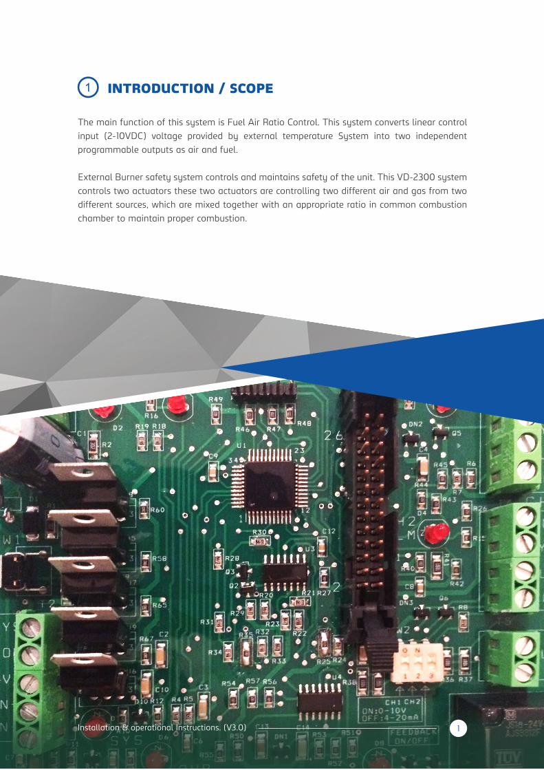
The main function of this system is Fuel Air Ratio Control. This system converts linear control
input (2-10VDC) voltage provided by external temperature System into two independent
programmable outputs as air and fuel.
External Burner safety system controls and maintains safety of the unit. This VD-2300 system
controls two actuators these two actuators are controlling two different air and gas from two
different sources, which are mixed together with an appropriate ratio in common combustion
chamber to maintain proper combustion.
INTRODUCTION / SCOPE1
2 Installation & operational Instructions. (V3.0)
SPECIFICATIONS2
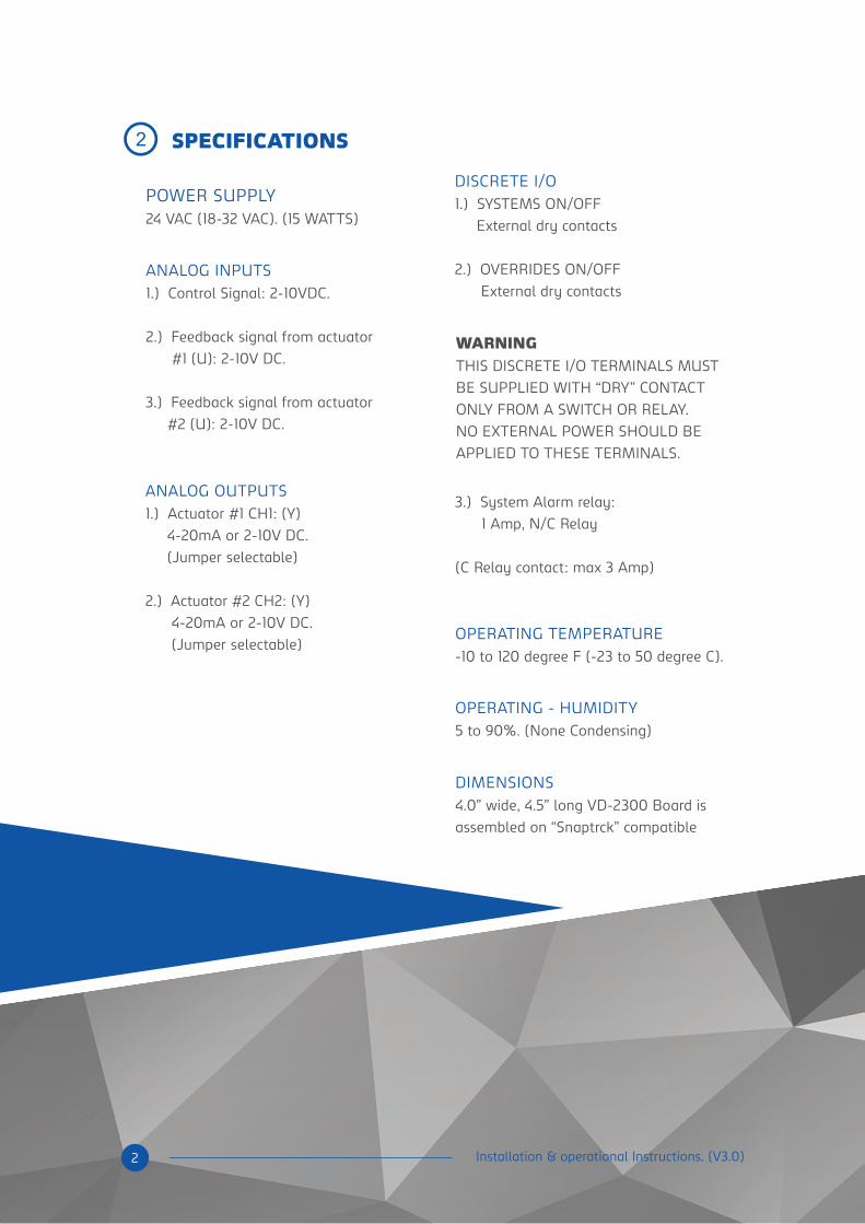
POWER SUPPLY24 VAC (18-32 VAC). (15 WATTS)
ANALOG INPUTS
1.) Control Signal: 2-10VDC.
2.) Feedback signal from actuator
#1 (U): 2-10V DC.
3.) Feedback signal from actuator
#2 (U): 2-10V DC.
3.) System Alarm relay:
1 Amp, N/C Relay
(C Relay contact: max 3 Amp)
WARNINGTHIS DISCRETE I/O TERMINALS MUST
BE SUPPLIED WITH “DRY” CONTACT
ONLY FROM A SWITCH OR RELAY.
NO EXTERNAL POWER SHOULD BE
APPLIED TO THESE TERMINALS.
ANALOG OUTPUTS
1.) Actuator #1 CH1: (Y)
4-20mA or 2-10V DC.
(Jumper selectable)
2.) Actuator #2 CH2: (Y)
4-20mA or 2-10V DC.
(Jumper selectable)
DISCRETE I/O
1.) SYSTEMS ON/OFF
External dry contacts
2.) OVERRIDES ON/OFF
External dry contacts
OPERATING TEMPERATURE
-10 to 120 degree F (-23 to 50 degree C).
OPERATING - HUMIDITY
5 to 90%. (None Condensing)
DIMENSIONS
4.0” wide, 4.5” long VD-2300 Board is
assembled on “Snaptrck” compatible
3 Installation & operational Instructions. (V3.0)
A) 24VAC
B) GND
C) SYS
D) COM
E) OVE
F) +IN
G) -COM
POWER SUPPLY
CONTROL INPUTS
Power supply Hot
24 VAC (18-32VAC).
Power supply Common
System OFF/ON signal
Common for both SYSTEM and OVERRIDE.
OVERRIDE OFF/ON signal
Control signal 2-10V DC
Control signal ground 0.00V
(Same as power supply common)
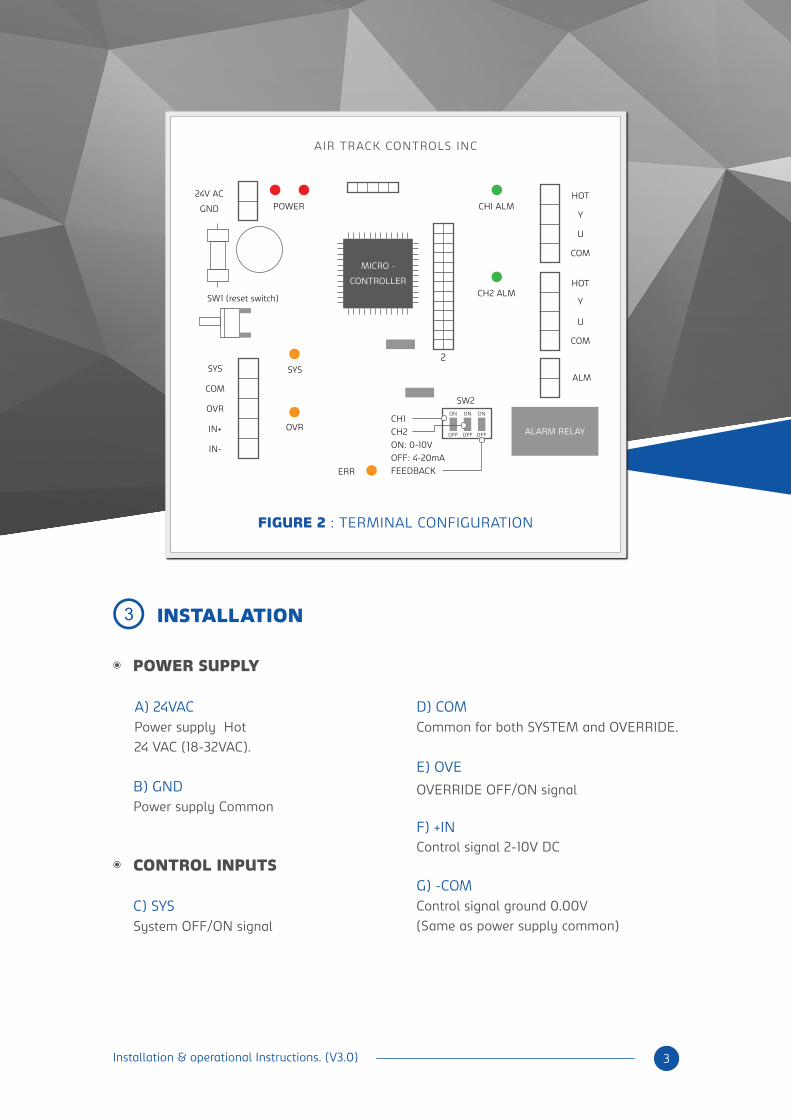
CHI ALMPOWER
SW1 (reset switch)
SYSSYS
COM
OVR
IN+
IN-
HOT
COM
Y
U
HOT
COM
Y
U
OVR
24V AC
GND
CH2 ALM
2
ALM
SW2ON ON ON
OFF OFF OFF
ERR
CH1
CH2
ON: 0-10V
OFF: 4-20mA
FEEDBACK
ALARM RELAY
MICRO -
CONTROLLER
AIR TRACK CONTROLS INC
FIGURE 2 : TERMINAL CONFIGURATION
INSTALLATION3
4 Installation & operational Instructions. (V3.0)
H) HOT I) Y
M) U
K) COM
D) ALM
I) Y
J) U
K) COM
CH#1 (ACTUATOR # 1)
INTERLOCK RELAY
K) HOT
CH#2 (ACTUATOR # 2)
Actuator 2 control signal:
4-20mA / 2-10V DC
Feedback signal from actuator #2
2-10V DC
Actuator Common 0 V
INTERLOCK Relay Contact, N/C contact.
1 Amps (max)
Power to Actuator. 24 VAC
Actuator Common 0 V
Feedback signal from actuator #1
2-10V DC
Actuator control signal:
4-20mA / 2-10V DC
Power to Actuator. 24 VAC.
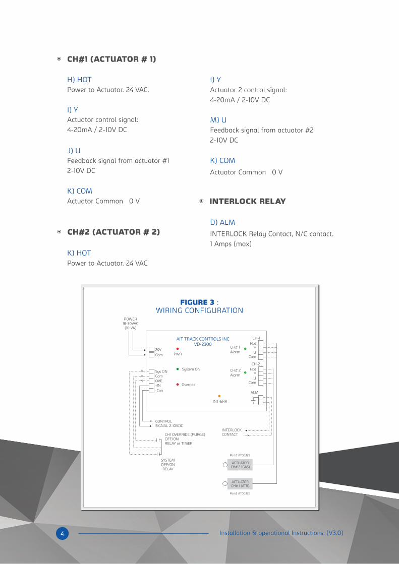
AIT TRACK CONTROLS INCVD-2300
PWR
POWER18-30VAC(10 VA)
SYSTEMOFF/ONRELAY
CONTROLSIGNAL 2-10VDC
INTERLOCKCONTACT
ACTUATORCH# 2 (GAS)
Part# AT00322
Part# AT00322
ACTUATORCH# 1 (ATR)
CH1 OVERRIDE (PURGE)OFF/ONRELAY or TIMER
System ONSys ON
CH-1Hot
YU
Com
CH-2
ALM
HotYU
Com
Com
Com24V
CH# 1Alarm
CH# 2Alarm
INT-ERR
OVE+IN-Con
Override
FIGURE 3 :WIRING CONFIGURATION
5 Installation & operational Instructions. (V3.0)
SYSTEM ON/OFF
Actuator Controller Board (VD-2300) constantly monitors two signals; SYSTEM and
OVERRIDE programmed as NO (normally open) relay contacts from the External source. When
a transition from ON to OFF state is detected on the SYSTEM contact or upon power-up the
SYSTEM contact is detected as open, the CH1(air) and CH2(gas) outputs are driven to 0V. The
SYSTEM contact is ignored during the actuators’ travel to return to their zero angle positions.
When both actuator feedback signals reach zero volts the SYSTEM contact are again
monitored and the outputs are kept at 0V as long as the SYSTEM contact is open.
OVERRIDE (PURGE)
When OVERRIDE contact is detected as ON while SYSTEM is OFF, Actuator Controller Board
sets predefined “Override set point” to Air actuator #1 only (CH1). CH2 signal is set to zero. The
OVR LED is turned ON; this function can be use for purging by external timer or relay to
activate this OVE contact. When OVERRIDE contact is detected as ON while SYSTEM is ON,
the Actuator Controller Board ignores OVERRIDE and sets “Override failed” alarm by blinking
the OVR LED.
HARDWARE DESCRIPTION AND SYSTEM OPERATION
Each actuator could have its own control voltage-angle transfer function, predefined by 9
(2,3,4,…,10) set points plus “Override set point” (for CH1 only), entered and saved manually by
means of separate Keypad/LCD Board plugged into the VD-2300 Board. Values between
defined set points will be calculated as linear-piecewise segments.
External temperature via “System control signal” sets control point for both actuators.
VD-2300 Board responds with two synchronized (2-10V or 4-20mA) output signals, CH1 (air)
and CH2 (gas), to turn each actuator/valve to preprogrammed 0-90 degrees angle, (best on
actual combustion.) According to pre programmed defined/saved voltage-angle transfer
function. System is always monitoring feedback signals from CH1- U and CH2-U, from both
actuators.
ACTUATOR MONITOR
VD-2300 Boards constantly monitors two feedback signals, CH1-U and CH2-U, from both
actuators. If either actuator feedback signal does not settle the feedback is assumed to have
failed and Actuator Controller Board will send 0V control signals to both actuators and set
“Actuator feedback failed” alarm by energizing corresponding LED for the failed feedback
channel, CH1 or CH2...And energize the alarm relay from normally close to normally open
position.
4
In case that Actuator Controller Board detects internal error both control outputs, CH1 and
CH2, will be automatically disconnected from the actuator board, driving the actuators to the
0V and energize the alarm relay.
ALARM RESET
VD-2300 will have a manual reset button. When this button is pressed the System will be
interrupted and the microcontroller will reinitiate.
NOTE
Cable length for the Actuator controller board to Actuator connections should not exceed 10ft.
For No feedback actuators with 4-20mA connections this length may be increased up to 30ft.
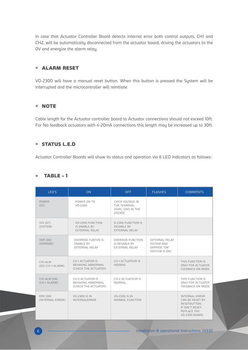
STATUS L.E.D
Actuator Controller Boards will show its status and operation via 6 LED indicators as follows:
LED’S
POWER(D2)
POWER ON TOVD-2300
VD-2300 FUNCTIONIS ENABLE BYEXTERNAL RELAY
D-2300 FUNCTION ISDESABLE BYEXTERNAL RELAY
CHICK VOLTAGE INTHE TERMINAL24VAC, GND IN THEVD2300
SYS (D7) (SYSTEM)
OVR (D6) (OVRRIDE)
CH1-ALM (D3) (CH-1 ALARM)
OVERRIDE FUNTEN ISENABLE BYEXTERNAL RELAY
CH-1 ACTUATOR ISBEHAVING ABNORMAL(CHECK THE ACTUATOR)
CH-1 ACTUATEOR ISNORMAL
THIS FUNCTION ISONLY FOR ACTUATERFEEDBACK ON MODE
CH1-ALM (D4) (CH-1 ALARM)
CH-2 ACTUATOR ISBEHAVING ABNORMAL(CHECK THE ACTUATOR)
CH-2 ACTUATEOR ISNORMAL
THIS FUNCTION ISONLY FOR ACTUATERFEEDBACK ON MODE
ERR (D8)(INTERNAL ERROR)
VD-2300 IS ININTERNALERROR
VD-2300 IS INNORMAL FUNCTION
INTERNAL ERRORCAN BE RESET BYRESETBUTTON.IF DIN”T RESET,REPLACE THEVD-2300 BOARD
OVERRIDE FUNCTIONIS DESABLE BYEXTERNAL RELAY
EXTERNAL RELAYSYSTEM ANDOVRRIDE “ON” (SYSTEM IS ON)
ON OFF FLASHES COMMENTS
6 Installation & operational Instructions. (V3.0)
TABLE - 1
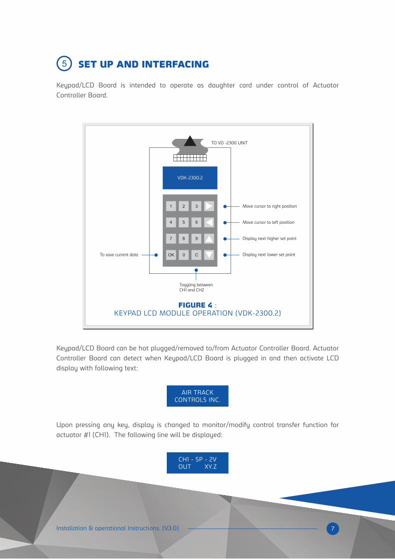
Keypad/LCD Board is intended to operate as daughter card under control of Actuator
Controller Board.
Keypad/LCD Board can be hot plugged/removed to/from Actuator Controller Board. Actuator
Controller Board can detect when Keypad/LCD Board is plugged in and then activate LCD
display with following text:
Upon pressing any key, display is changed to monitor/modify control transfer function for
actuator #1 (CH1). The following line will be displayed:
VDK-2300.2
Move cursor to right position
TO VD -2300 UNIT
Move cursor to left position
Display next higher set point
Display next lower set point
Toggling betweenCH1 and CH2
To save current data
1 2 3
4 5 6
7 8 9
OK 0 C
AIR TRACKCONTROLS INC.
CH1 - SP - 2VOUT XY.Z
7 Installation & operational Instructions. (V3.0)
5 SET UP AND INTERFACING
FIGURE 4 :KEYPAD LCD MODULE OPERATION (VDK-2300.2)
8 Installation & operational Instructions. (V3.0)
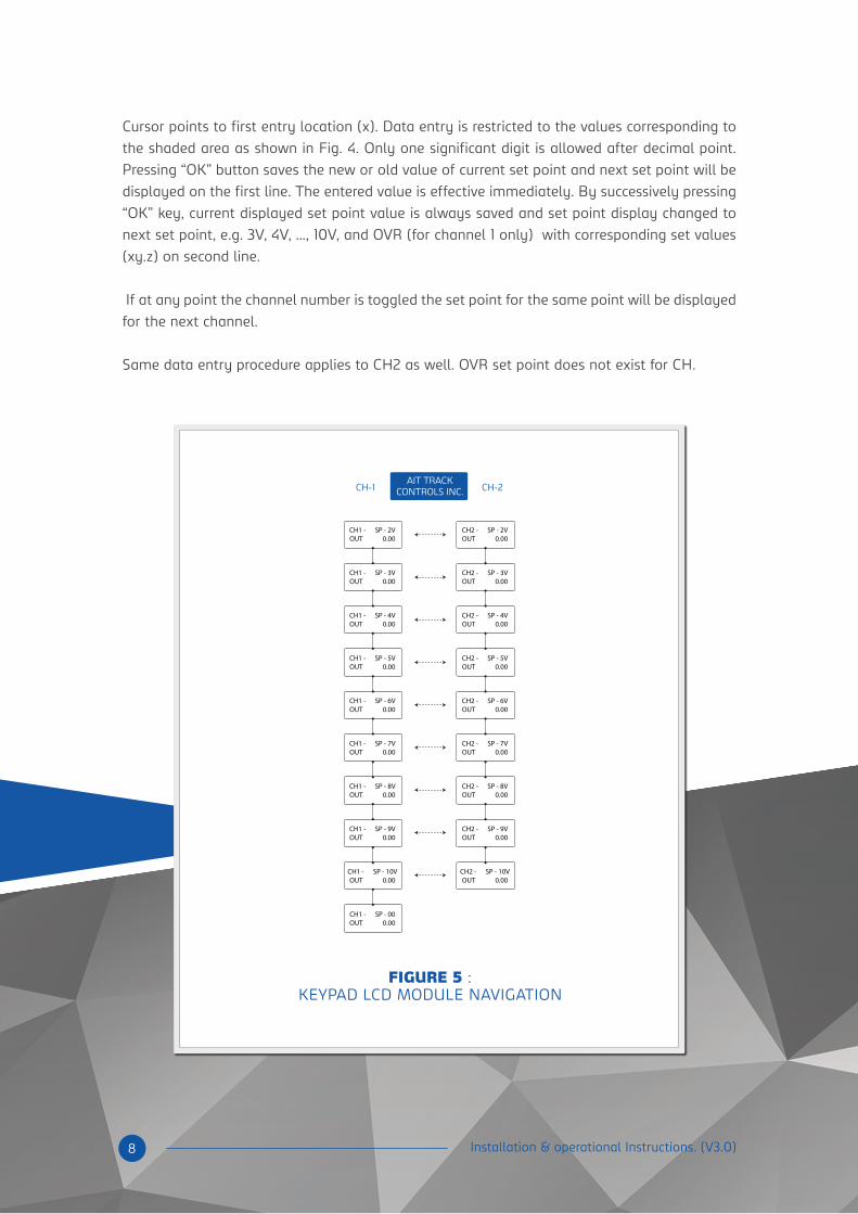
Cursor points to first entry location (x). Data entry is restricted to the values corresponding to
the shaded area as shown in Fig. 4. Only one significant digit is allowed after decimal point.
Pressing “OK” button saves the new or old value of current set point and next set point will be
displayed on the first line. The entered value is effective immediately. By successively pressing
“OK” key, current displayed set point value is always saved and set point display changed to
next set point, e.g. 3V, 4V, …, 10V, and OVR (for channel 1 only) with corresponding set values
(xy.z) on second line.
If at any point the channel number is toggled the set point for the same point will be displayed
for the next channel.
Same data entry procedure applies to CH2 as well. OVR set point does not exist for CH.
FIGURE 5 :KEYPAD LCD MODULE NAVIGATION
CH1 - SP - 2VOUT 0.00
CH1 - SP - 3VOUT 0.00
CH1 - SP - 4VOUT 0.00
CH1 - SP - 5VOUT 0.00
CH1 - SP - 6VOUT 0.00
CH1 - SP - 7VOUT 0.00
CH1 - SP - 8VOUT 0.00
CH1 - SP - 9VOUT 0.00
CH1 - SP - 10VOUT 0.00
CH1 - SP - 00OUT 0.00
CH2 - SP - 2VOUT 0.00
CH2 - SP - 3VOUT 0.00
CH2 - SP - 4VOUT 0.00
CH2 - SP - 5VOUT 0.00
CH2 - SP - 6VOUT 0.00
CH2 - SP - 7VOUT 0.00
CH2 - SP - 8VOUT 0.00
CH2 - SP - 9VOUT 0.00
CH2 - SP - 10VOUT 0.00
CH-1 CH-2AIT TRACK
CONTROLS INC.
OV
10V
OUTPUT
INPUT
9V
8V
7V
6V
5V
4V
3V
2V
1V
0V
1V 2V 3V 4V 5V 6V 7V 8V 9V 1OV
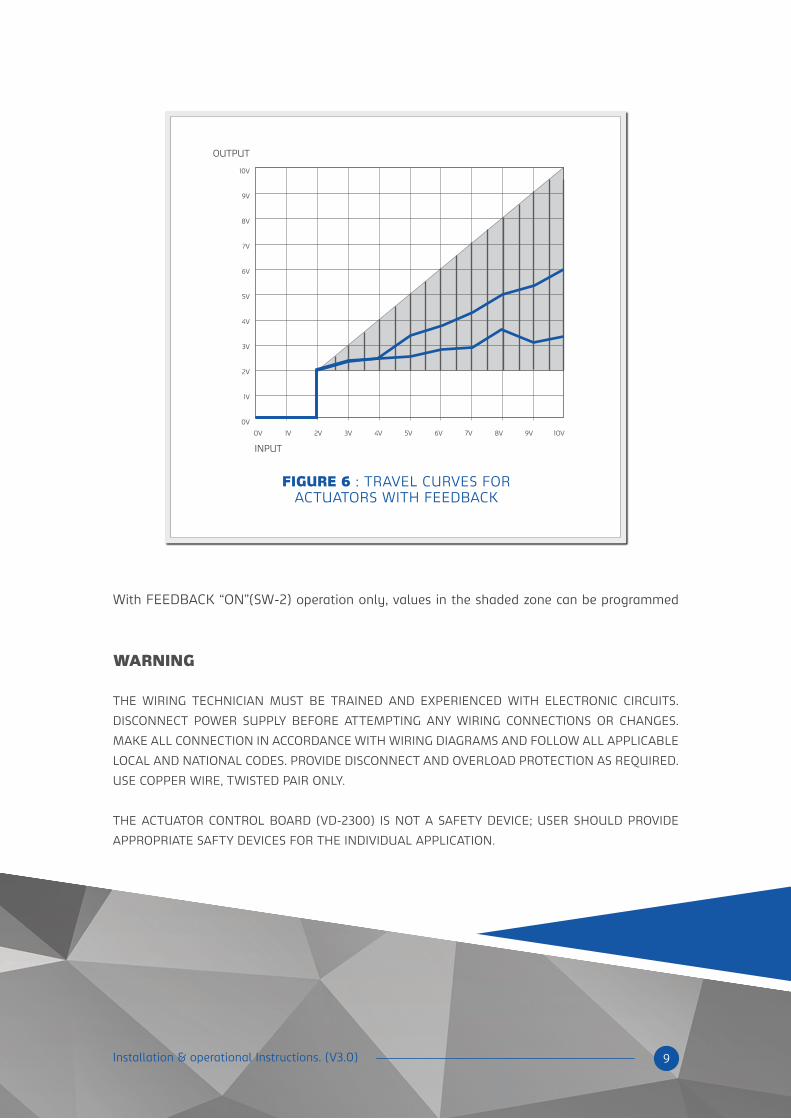
FIGURE 6 : TRAVEL CURVES FORACTUATORS WITH FEEDBACK
9 Installation & operational Instructions. (V3.0)
With FEEDBACK “ON”(SW-2) operation only, values in the shaded zone can be programmed
WARNING
THE WIRING TECHNICIAN MUST BE TRAINED AND EXPERIENCED WITH ELECTRONIC CIRCUITS.
DISCONNECT POWER SUPPLY BEFORE ATTEMPTING ANY WIRING CONNECTIONS OR CHANGES.
MAKE ALL CONNECTION IN ACCORDANCE WITH WIRING DIAGRAMS AND FOLLOW ALL APPLICABLE
LOCAL AND NATIONAL CODES. PROVIDE DISCONNECT AND OVERLOAD PROTECTION AS REQUIRED.
USE COPPER WIRE, TWISTED PAIR ONLY.
THE ACTUATOR CONTROL BOARD (VD-2300) IS NOT A SAFETY DEVICE; USER SHOULD PROVIDE
APPROPRIATE SAFTY DEVICES FOR THE INDIVIDUAL APPLICATION.

6 SET POINT RECORD SHEET
10 Installation & operational Instructions. (V3.0)
JOB PROFILE
DATE:
UNIT SERIAL # MODEL # GAS INPUT BURNER MODEL GAS ORIFICE BUTTERFLY VALVE MANIFOLD PRESSURE
TRAVEL CURVES
10
2 3 4 5 6 7 8 9 10
1
2
3
4
5
6
7
8
9
10
OUTPUT
INPUT
INPUT CH-1 CH-2 O 2 EX AIR CO 2 CO
VOLTS
2
3
4
5
6
7
8
9
10
PPM%%%
COMMENTS:

2381 BANKSIDE DRIVE,
MISSISSAUGA, ON,
L5M-6E5, CANADA.
Phone: (905) 330 4056
Fax: (905) 812 9136
Email: [email protected]
AIR TRACK INC