Embed Size (px)
Citation preview

Doc 4444
ATM/501
Procedures for
Air Navigation Services
AIR TRAFFIC MANAGEMENT
This edition incorporates all amendments
approved by the Council prior to 27 May 2008
and supersedes, on 15 November 2012,
all previous editions of Doc 4444.
Fifteenth Edition - 2007
International Civil Aviation Organization

1
AMENDMENT TO THE FOREWORD OF THE PANS-ATM, FIFTEENTH EDITION
Add the following in Table A, page (xv):
Amendment
Source(s)
Subject
Approved
Applicable
1 Flight Plan Study Group
(FPLSG)
Update the ICAO model flight plan form.
27 May 2008
15 November 2012

2
PROCEDURES FOR AIR NAVIGATION SERVICES — AIR
TRAFFIC MANAGEMENT (PANS-ATM, DOC 4444)
. . .
CHAPTER 4. GENERAL PROVISIONS FOR AIR TRAFFIC SERVICES
. . .
4.4 FLIGHT PLAN
4.4.1 Flight plan form
Note.— Procedures for the use of repetitive flight plans are contained in Chapter 16, Section 16.4.
. . .
4.4.1.3 Operators and air traffic services units should comply with:
a) the instructions for completion of the flight plan form and the repetitive flight plan listing
form given in Appendix 2; and
b) any constraints identified in relevant Aeronautical Information Publications (AIPs).
Note 1.— Failure to adhere to the provisions of Appendix 2 or any constraint identified in relevant
AIPs may result in data being rejected, processed incorrectly or lost.
Note 2.— The instructions for completing the flight plan form given in Appendix 2 may be
conveniently printed on the inside cover of flight plan form pads, or posted in briefing rooms.
. . .
4.4.2 Submission of a flight plan
4.4.2.1 PRIOR TO DEPARTURE
4.4.2.1.1 Flight plans shall not be submitted more than 120 hours before the estimated off-block
time of a flight.
4.4.2.1.12 Except when other arrangements have been made for submission of repetitive flight
plans, a flight plan submitted prior to departure should be submitted to the air traffic services reporting
office at the departure aerodrome. If no such unit exists at the departure aerodrome, the flight plan should
be submitted to the unit serving or designated to serve the departure aerodrome.
4.4.2.1.23 In the event of a delay of 30 minutes in excess of the estimated off-block time for a
controlled flight or a delay of one hour for an uncontrolled flight for which a flight plan has been
submitted, the flight plan should be amended or a new flight plan submitted and the old flight plan
cancelled, whichever is applicable.

3
CHAPTER 11. AIR TRAFFIC SERVICES MESSAGES
. . .
11.4 MESSAGE TYPES AND
THEIR APPLICATION
. . .
11.4.2 Movement and control messages
. . .
11.4.2.2 MOVEMENT MESSAGES
. . .
11.4.2.2.2 FILED FLIGHT PLAN (FPL) MESSAGES
Note.— Instructions for the transmission of an FPL message are contained in Appendix 2.
. . .
11.4.2.2.2.5 FPL messages shall normallyshould be transmitted immediately after the filing of the
flight plan. However, iIf a flight plan is filed more than 24 hours in advance of the estimated off-block
time of the flight to which it refers, that flight plan shall be held in abeyance until at most 24 hours before
the flight begins so as to avoid the need for the insertion of a date group into that the date of the flight
departure shall be inserted in Item 18 of the flight plan. In addition, if a flight plan is filed early and the
provisions of 11.4.2.2.2.2 b) or e) or 11.4.2.2.2.3 apply, transmission of the FPL message may be
withheld until one hour before the estimated off-block time, provided that this will permit each air traffic
services unit concerned to receive the information at least 30 minutes before the time at which the aircraft
is estimated to enter its area of responsibility.
. . .
11.4.2.2.4 MODIFICATION (CHG) MESSAGES
A CHG message shall be transmitted when any change is to be made to basic flight plan data
contained in previously transmitted FPL or RPL data. The CHG message shall be sent to those recipients
of basic flight plan data which are affected by the change. Relevant revised basic flight plan data shall be
provided to such affected entities not previously having received this.
Note.— See 11.4.2.3.4 concerning notification of a change to coordination data contained in a
previously transmitted current flight plan or estimate message.
. . .
4
APPENDIX 2. FLIGHT PLAN
. . .
2. Instructions for the completion of
the flight plan form
. . .
2.2 Instructions for insertion
of ATS data
Complete Items 7 to 18 as indicated hereunder.
Complete also Item 19 as indicated hereunder, when so required by the appropriate ATS authority or
when otherwise deemed necessary.
Note 1.— Item numbers on the form are not consecutive, as they correspond to Field Type numbers in
ATS messages.
Note 2.— Air traffic services data systems may impose communications or processing constraints on
information in filed flight plans. Possible constraints may, for example, be limits with regard to item
length, number of elements in the route item or total flight plan length. Significant constraints are
documented in the relevant Aeronautical Information Publication.
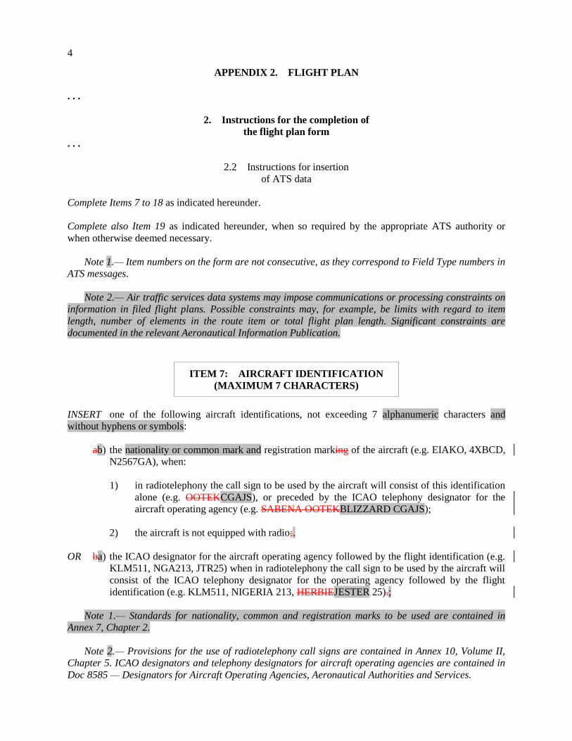
ITEM 7: AIRCRAFT IDENTIFICATION
(MAXIMUM 7 CHARACTERS)
INSERT one of the following aircraft identifications, not exceeding 7 alphanumeric characters and
without hyphens or symbols:
ab) the nationality or common mark and registration marking of the aircraft (e.g. EIAKO, 4XBCD,
N2567GA), when:
1) in radiotelephony the call sign to be used by the aircraft will consist of this identification
alone (e.g. OOTEKCGAJS), or preceded by the ICAO telephony designator for the
aircraft operating agency (e.g. SABENA OOTEKBLIZZARD CGAJS);
2) the aircraft is not equipped with radio;.
OR ba) the ICAO designator for the aircraft operating agency followed by the flight identification (e.g.
KLM511, NGA213, JTR25) when in radiotelephony the call sign to be used by the aircraft will
consist of the ICAO telephony designator for the operating agency followed by the flight
identification (e.g. KLM511, NIGERIA 213, HERBIEJESTER 25).;
Note 1.— Standards for nationality, common and registration marks to be used are contained in
Annex 7, Chapter 2.
Note 2.— Provisions for the use of radiotelephony call signs are contained in Annex 10, Volume II,
Chapter 5. ICAO designators and telephony designators for aircraft operating agencies are contained in
Doc 8585 — Designators for Aircraft Operating Agencies, Aeronautical Authorities and Services.

5
ITEM 8: FLIGHT RULES AND TYPE OF
FLIGHT (ONE OR TWO CHARACTERS)
Flight rules
INSERT one of the following letters to denote the category of flight rules with which the pilot intends to
comply:
I if it is intended that the entire flight will be operated under the IFR
V if it is intended that the entire flight will be operated under the VFR
Y if the flight initially will be operated under the IFR first) and specify in Item 15 the point,
followed by one or more subsequent changes of flight rules or
Z if the flight initially will be operated under the VFR first), followed by one or more
subsequent changes of flight rules
Specify in Item 15 the point or points at which a change of flight rules is planned.
Type of flight
INSERT one of the following letters to denote the type of flight when so required by the appropriate
ATS authority:
S if scheduled air service
N if non-scheduled air transport operation
G if general aviation
M if military
X if other than any of the defined categories above.
Specify status of a flight following the indicator STS in Item 18, or when necessary to denote
other reasons for specific handling by ATS, indicate the reason following the indicator RMK in
Item 18.
. . .
ITEM 10: EQUIPMENT AND CAPABILITIES
Capabilities comprise the following elements:
a) presence of relevant serviceable equipment on board the aircraft;
b) equipment and capabilities commensurate with flight crew qualifications; and
c) where applicable, authorization from the appropriate authority.

6
Radio communication, navigation and
approach aid equipment and capabilities
INSERT one letter as follows:
N if no COM/NAV/approach aid equipment for the route to be flown is carried, or the
equipment is unserviceable,
OR S if standard COM/NAV/approach aid equipment for the route to be flown is carried and
serviceable (see Note 1),
AND/OR
INSERT one or more of the following letters to indicate the serviceable COM/NAV/approach aid
equipment and capabilities available and serviceable:
A (Not allocated)GBAS
landing system
J7 CPDLC FANS 1/A SATCOM
(Iridium)
B (Not allocated)LPV (APV
with SBAS)
K (MLS)
C LORAN C L ILS
D DME M1 OmegaATC RTF SATCOM
(INMARSAT)
E1 (Not allocated)FMC WPR
ACARS
M2 ATC RTF (MTSAT)
E2 D-FIS ACARS M3 ATC RTF (Iridium)
E3 PDC ACARS O VOR
F ADF PP1–P9 (Not allocated)Reserved for
RCP
G (GNSS) (See Note 2) Q (Not allocated)
H HF RTF R RNP type certificationPBN
approved (see Note 54)
I Inertial Navigation T TACAN
J1 (Data Link)CPDLC ATN
VDL Mode 2(See Note 3)
U UHF RTF
J2 CPDLC FANS 1/A HFDL V VHF RTF
J3 CPDLC FANS 1/A VDL
Mode 4
W RVSM approved
J4 CPDLC FANS 1/A VDL
Mode 2
X MNPS approved
J5 CPDLC FANS 1/A
SATCOM (INMARSAT)
Y when prescribed by ATSVHF
with 8.33 kHz channel spacing
capability
J6 CPDLC FANS 1/A
SATCOM (MTSAT)
Z Other equipment carried or
other capabilities (see Note 25)
Any alphanumeric characters not indicated above are reserved.

7
Note 1.— If the letter S is used, sStandard equipment is considered to be VHF RTF, ADF, VOR and
ILS, unless another combination is prescribed by the appropriate ATS authority.
Note 2.— If the letter G is used, the types of external GNSS augmentation, if any, are specified in
Item 18 following the indicator NAV/ and separated by a space.
Note 25.— If the letter Z is used, specify in Item 18 the other equipment carried or other capabilities,
preceded by COM/ and/or, NAV/ and/or DAT, as appropriate.
Note 3.— If the letter J is used, specify in Item 18 the equipment carried, preceded by DAT/
followed by one or more letters as appropriate.See RTCA/EUROCAE Interoperability Requirements
Standard For ATN Baseline 1 (ATN B1 INTEROP Standard – DO-280B/ED-110B) for data link services
air traffic control clearance and information/air traffic control communications management/air traffic
control microphone check.
Note 46.— Information on navigation capability is provided to ATC for clearance and routing
purposes.
Note 54.— Inclusion ofIf the letter R is used, the performance based navigation levels that can be met
are specified in Item 18 following the indicator PBN/. Guidance material on the application of
performance based navigation to a specific indicates that an aircraft meets the RNP type prescribed for
the route segment(s), route(s) and/or area concerned is contained in the Performance-Based Navigation
Manual (Doc 9613).
Surveillance equipment
and capabilities
INSERT N if no surveillance equipment for the route to be flown is carried, or the equipment is
unserviceable,
OR
INSERT one or twomore of the following lettersdescriptors, to a maximum of 20 characters, to describe
the serviceable surveillance equipment carriedand/or capabilities on board:
SSR equipmentSSR Modes A and C
N Nil
A Transponder — Mode A (4 digits — 4 096 codes)
C Transponder — Mode A (4 digits — 4 096 codes) and Mode C
SSR Mode S
X Transponder — Mode S without both aircraft identification and pressure-altitude transmission
E Transponder — Mode S, including aircraft identification, pressure-altitude and extended
squitter (ADS-B) capability
H Transponder — Mode S, including aircraft identification, pressure-altitude and enhanced
surveillance capability
I Transponder — Mode S, including aircraft identification, but no pressure-altitude capability
L Transponder — Mode S, including aircraft identification, pressure-altitude, extended squitter
(ADS-B) and enhanced surveillance capability
P Transponder — Mode S, including pressure-altitude, but no aircraft identification

8
transmissioncapability
I Transponder — Mode S, including aircraft identification transmission, but no pressure-altitude
transmission
S Transponder — Mode S, including both pressure altitude and aircraft identification
transmissioncapability
X Transponder — Mode S with neither aircraft identification nor pressure-altitude capability
Note.— Enhanced surveillance capability is the ability of the aircraft to down-link aircraft derived
data via a Mode S transponder.
ADS-B
B1 ADS-B with dedicated 1090 MHz ADS-B “out” capability
B2 ADS-B with dedicated 1090 MHz ADS-B “out” and “in” capability
U1 ADS-B “out” capability using UAT
U2 ADS-B “out” and “in” capability using UAT
V1 ADS-B “out” capability using VDL Mode 4
V2 ADS-B “out” and “in” capability using VDL Mode 4
ADS-C
D1 ADS-C with FANS 1/A capabilities
G1 ADS-C with ATN capabilities
ADS equipment
D ADS capability
Alphanumeric characters not indicated above are reserved.
Example: ADE3RV/HB2U2V2G1
Note.— Additional surveillance application should be listed in Item 18 following the indicator SUR/ .
ITEM 13: DEPARTURE AERODROME
AND TIME (8 CHARACTERS)
INSERT the ICAO four-letter location indicator of the departure aerodrome as specified in Doc 7910,
Location Indicators,
OR, if no location indicator has been assigned,
INSERT ZZZZ and SPECIFY, in Item 18, the name and location of the aerodrome preceded by DEP/ ,
OR, the first point of the route or the marker radio beacon preceded by DEP/…, if the aircraft has not
taken off from the aerodrome,
OR, if the flight plan is received from an aircraft in flight,
INSERT AFIL, and SPECIFY, in Item 18, the ICAO four-letter location indicator of the location of the
ATS unit from which supplementary flight plan data can be obtained, preceded by DEP/ .

9
THEN, WITHOUT A SPACE,
INSERT for a flight plan submitted before departure, the estimated off-block time (EOBT),
OR, for a flight plan received from an aircraft in flight, the actual or estimated time over the first
point of the route to which the flight plan applies.
ITEM 15: ROUTE
INSERT the first cruising speed as in (a) and the first cruising level as in (b), without a space between
them.
THEN, following the arrow, INSERT the route description as in (c).
(a) Cruising speed (maximum 5 characters)
INSERT the True Air Speed for the first or the whole cruising portion of the flight, in terms of:
Kilometres per hour, expressed as K followed by 4 figures (e.g. K0830), or
Knots, expressed as N followed by 4 figures (e.g. N0485), or
True Mach number, when so prescribed by the appropriate ATS authority, to the nearest
hundredth of unit Mach, expressed as M followed by 3 figures (e.g. M082).
(b) Cruising level (maximum 5 characters)
INSERT the planned cruising level for the first or the whole portion of the route to be flown, in terms of:
Flight level, expressed as F followed by 3 figures (e.g. F085; F330), or
*Standard Metric Level in tens of metres, expressed as S followed by 4 figures (e.g. S1130), or
Altitude in hundreds of feet, expressed as A followed by 3 figures (e.g. A045; A100), or
Altitude in tens of metres, expressed as M followed by 4 figures (e.g. M0840), or
for uncontrolled VFR flights, the letters VFR.
*When so prescribed by the appropriate ATS authorities.
(c) Route (including changes of speed,
level and/or flight rules)
Flights along designated ATS routes
INSERT, if the departure aerodrome is located on or connected to the ATS route, the designator of the
first ATS route,
10
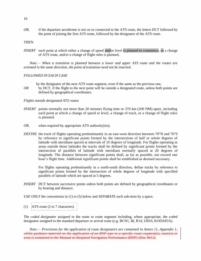
OR, if the departure aerodrome is not on or connected to the ATS route, the letters DCT followed by
the point of joining the first ATS route, followed by the designator of the ATS route.
THEN
INSERT each point at which either a change of speed and/or level is planned to commence, or a change
of ATS route, and/or a change of flight rules is planned,
Note.— When a transition is planned between a lower and upper ATS route and the routes are
oriented in the same direction, the point of transition need not be inserted.
FOLLOWED IN EACH CASE
by the designator of the next ATS route segment, even if the same as the previous one,
OR by DCT, if the flight to the next point will be outside a designated route, unless both points are
defined by geographical coordinates.
Flights outside designated ATS routes
INSERT points normally not more than 30 minutes flying time or 370 km (200 NM) apart, including
each point at which a change of speed or level, a change of track, or a change of flight rules
is planned.
OR, when required by appropriate ATS authority(ies),
DEFINE the track of flights operating predominantly in an east-west direction between 70°N and 70°S
by reference to significant points formed by the intersections of half or whole degrees of
latitude with meridians spaced at intervals of 10 degrees of longitude. For flights operating in
areas outside those latitudes the tracks shall be defined by significant points formed by the
intersection of parallels of latitude with meridians normally spaced at 20 degrees of
longitude. The distance between significant points shall, as far as possible, not exceed one
hour’s flight time. Additional significant points shall be established as deemed necessary.
For flights operating predominantly in a north-south direction, define tracks by reference to
significant points formed by the intersection of whole degrees of longitude with specified
parallels of latitude which are spaced at 5 degrees.
INSERT DCT between successive points unless both points are defined by geographical coordinates or
by bearing and distance.
USE ONLY the conventions in (1) to (5) below and SEPARATE each sub-item by a space.
(1) ATS route (2 to 7 characters)
The coded designator assigned to the route or route segment including, where appropriate, the coded
designator assigned to the standard departure or arrival route (e.g. BCN1, Bl, R14, UB10, KODAP2A).
Note.— Provisions for the application of route designators are contained in Annex 11, Appendix 1,
whilst guidance material on the application of an RNP type to a specific route segment(s), route(s) or
area is contained in the Manual on Required Navigation Performance (RNP) (Doc 9613).

11
(2) Significant point (2 to 11 characters)
The coded designator (2 to 5 characters) assigned to the point (e.g. LN, MAY, HADDY), or,
if no coded designator has been assigned, one of the following ways:
— Degrees only (7 characters):
2 figures describing latitude in degrees, followed by “N” (North) or “S” (South), followed by 3
figures describing longitude in degrees, followed by “E” (East) or “W” (West). Make up the correct
number of figures, where necessary, by insertion of zeros, e.g. 46N078W.
— Degrees and minutes (11 characters):
4 figures describing latitude in degrees and tens and units of minutes followed by “N” (North) or “S”
(South), followed by 5 figures describing longitude in degrees and tens and units of minutes, followed
by “E” (East) or “W” (West). Make up the correct number of figures, where necessary, by insertion of
zeros, e.g. 4620N07805W.
— Bearing and distance from a navigation aidreference point:
The identification of the navigation aid (normally a VOR)reference point, in the form of 2 or 3
characters, THENfollowed by the bearing from the aidpoint in the form of 3 figures giving degrees
magnetic, THENfollowed by the distance from the aidpoint in the form of 3 figures expressing
nautical miles. In areas of high latitude where it is determined by the appropriate authority that
reference to degrees magnetic is impractical, degrees true may be used. Make up the correct number
of figures, where necessary, by insertion of zeros — e.g. a point 180° magnetic at a distance of 40
nautical miles from VOR “DUB” should be expressed as DUB180040.
(3) Change of speed or level
(maximum 21 characters)
The point at which a change of speed (5% TAS or 0.01 Mach or more) or a change of level is planned to
commence, expressed exactly as in (2) above, followed by an oblique stroke and both the cruising speed
and the cruising level, expressed exactly as in (a) and (b) above, without a space between them, even
when only one of these quantities will be changed.
Examples: LN/N0284A045
MAY/N0305Fl80
HADDY/N0420F330
4602N07805W/N0500F350
46N078W/M082F330
DUB180040/N0350M0840
(4) Change of flight rules
(maximum 3 characters)
The point at which the change of flight rules is planned, expressed exactly as in (2) or (3) above as
appropriate, followed by a space and one of the following:

12
VFR if from IFR to VFR
IFR if from VFR to IFR
Examples: LN VFR
LN/N0284A050 IFR
(5) Cruise climb (maximum 28 characters)
The letter C followed by an oblique stroke; THEN the point at which cruise climb is planned to start,
expressed exactly as in (2) above, followed by an oblique stroke; THEN the speed to be maintained
during cruise climb, expressed exactly as in (a) above, followed by the two levels defining the layer to be
occupied during cruise climb, each level expressed exactly as in (b) above, or the level above which
cruise climb is planned followed by the letters PLUS, without a space between them.
Examples: C/48N050W/M082F290F350
C/48N050W/M082F290PLUS
C/52N050W/M220F580F620.
ITEM 16: DESTINATION AERODROME AND
TOTAL ESTIMATED ELAPSED TIME,
DESTINATION ALTERNATE AERODROME(S)
Destination aerodrome and total
estimated elapsed time (8 characters)
INSERT the ICAO four-letter location indicator of the destination aerodrome followed, without a space,
by the total estimated elapsed timeas specified in Doc 7910, Location Indicators,
OR , if no location indicator has been assigned,
INSERT ZZZZ followed, without a space, by the total estimated elapsed time, and SPECIFY in Item 18
the name and location of the aerodrome, preceded by DEST/ .
THEN WITHOUT A SPACE
INSERT the total estimated elapsed time.
Note.— For a flight plan received from an aircraft in flight, the total estimated elapsed time is the
estimated time from the first point of the route to which the flight plan applies to the termination point of
the flight plan.
Destination aAlternate aerodrome(s) (4 characters)
INSERT the ICAO four-letter location indicator(s) of not more than two destination alternate
aerodromes, as specified in Doc 7910, Location Indicators, separated by a space,
OR, if no location indicator has been assigned to the destination alternate aerodrome(s),

13
INSERT ZZZZ and SPECIFY in Item 18 the name and location of the destination alternate aerodrome(s),
preceded by ALTN/ .
ITEM 18: OTHER INFORMATION
Note.— Use of indicators not included under this item may result in data being rejected, processed
incorrectly or lost.
Hyphens or oblique strokes should only be used as prescribed below.
INSERT 0 (zero) if no other information,
OR, any other necessary information in the preferred sequence shown hereunder, in the form of the
appropriate indicator selected from those defined hereunder followed by an oblique stroke and
the information to be recorded:
STS/ Reason for special handling by ATS, e.g. a search and rescue mission, as follows:
ALTRV: for a flight operated in accordance with an altitude reservation;
ATFMX: for a flight approved for exemption from ATFM measures by the appropriate ATS
authority;
FFR: fire-fighting;
FLTCK: flight check for calibration of navaids;
HAZMAT: for a flight carrying hazardous material;
HEAD: a flight with Head of State status;
HOSP: for a medical flight declared by medical authorities;
HUM: for a flight operating on a humanitarian mission;
MARSA: for a flight for which a military entity assumes responsibility for separation of
military aircraft;
MEDEVAC: for a life critical medical emergency evacuation;
NONRVSM: for a non-RVSM capable flight intending to operate in RVSM airspace;
SAR: for a flight engaged in a search and rescue mission; and
STATE: for a flight engaged in military, customs or police services.
Other reasons for special handling by ATS shall be denoted under the designator RMK/.
PBN/ Indication of RNAV and/or RNP capabilities. Include as many of the descriptors below, as
apply to the flight, up to a maximum of 8 entries, i.e. a total of not more than 16 characters.
RNAV SPECIFICATIONS
A1 RNAV 10 (RNP 10)
B1 RNAV 5 all permitted sensors
B2 RNAV 5 GNSS
B3 RNAV 5 DME/DME
B4 RNAV 5 VOR/DME
B5 RNAV 5 INS or IRS
B6 RNAV 5 LORANC
C1 RNAV 2 all permitted sensors
C2 RNAV 2 GNSS

14
C3 RNAV 2 DME/DME
C4 RNAV 2 DME/DME/IRU
D1 RNAV 1 all permitted sensors
D2 RNAV 1 GNSS
D3 RNAV 1 DME/DME
D4 RNAV 1 DME/DME/IRU
RNP SPECIFICATIONS
L1 RNP 4
O1 Basic RNP 1 all permitted sensors
O2 Basic RNP 1 GNSS
O3 Basic RNP 1 DME/DME
O4 Basic RNP 1 DME/DME/IRU
S1 RNP APCH
S2 RNP APCH with BARO-VNAV
T1 RNP AR APCH with RF (special authorization required)
T2 RNP AR APCH without RF (special authorization required)
Combinations of alphanumeric characters not indicated above are reserved.
EET/ Significant points or FIR boundary designators and accumulated estimated elapsed times to
such points or FIR boundaries, when so prescribed on the basis of regional air navigation
agreements, or by the appropriate ATS authority.
Examples: EET/CAP0745 XYZ0830
EET/EINN0204
RIF/ The route details to the revised destination aerodrome, followed by the ICAO four-letter
location indicator of the aerodrome. The revised route is subject to reclearance in flight.
Examples: RIF/DTA HEC KLAX
Examples: RIF/ESP G94 CLA YPPH
Examples: RIF/LEMD
REG/ The registration markings of the aircraft, if different from the aircraft identification in Item 7.
SEL/ SELCAL Code, if so prescribed by the appropriate ATS authority.
OPR/ Name of the operator, if not obvious from the aircraft identification in Item 7.
STS/ Reason for special handling by ATS, e.g. hospital aircraft, one engine inoperative, e.g.
STS/HOSP, STS/ONE ENG INOP.
TYP/ Type(s) of aircraft, preceded if necessary by number(s) of aircraft, if ZZZZ is inserted in
Item 9.
PER/ Aircraft performance data, if so prescribed by the appropriate ATS authority.

15
COM/ Significant data related to communication equipment as required by the appropriate ATS
authority, e.g. COM/UHF only.
DAT/ Significant data related to data link capability, using one or more of the letters S, H, V and M,
e.g. DAT/S for satellite data link, DAT/H for HF data link, DAT/V for VHF data link, DAT/M
for SSR Mode S data link.
NAV/ Significant data related to navigation equipment, other than specified in PBN/, as required by
the appropriate ATS authority. Indicate GNSS augmentation under this indicator, with a space
between two or more methods of augmentation, e.g. NAV/GBAS SBAS.
COM/ Indicate communications applications or capabilities not specified in Item 10a.
DAT/ Indicate data applications or capabilities not specified in 10a.
SUR/ Include surveillance applications or capabilities not specified in Item 10b.
DEP/ Name and location of departure aerodrome, if ZZZZ is inserted in Item 13, or the ICAO four-
letter location indicator of the location of the ATS unit from which supplementary flight plan
data can be obtained, if AFIL is inserted in Item 13. For aerodromes not listed in the relevant
Aeronautical Information Publication, indicate location as follows:
With 4 figures describing latitude in degrees and tens and units of minutes followed by “N”
(North) or “S” (South), followed by 5 figures describing longitude in degrees and tens and units
of minutes, followed by “E” (East) or “W” (West). Make up the correct number of figures,
where necessary, by insertion of zeros, e.g. 4620N07805W (11 characters).
OR, Bearing and distance from the nearest significant point, as follows:
The identification of the significant point followed by the bearing from the point in the form of
3 figures giving degrees magnetic, followed by the distance from the point in the form of
3 figures expressing nautical miles. In areas of high latitude where it is determined by the
appropriate authority that reference to degrees magnetic is impractical, degrees true may be
used. Make up the correct number of figures, where necessary, by insertion of zeros, e.g. a
point of 180° magnetic at a distance of 40 nautical miles from VOR “DUB” should be
expressed as DUB180040.
OR, The first point of the route (name or LAT/LONG) or the marker radio beacon, if the aircraft has
not taken off from an aerodrome.
DEST/ Name and location of destination aerodrome, if ZZZZ is inserted in Item 16. For aerodromes
not listed in the relevant Aeronautical Information Publication, indicate location in LAT/LONG
or bearing and distance from the nearest significant point, as described under DEP/ above.
DOF/ The date of flight departure in a six figure format (YYMMDD, where YY equals the year, MM
equals the month and DD equals the day).
REG/ The nationality or common mark and registration mark of the aircraft, if different from the
aircraft identification in Item 7.
16
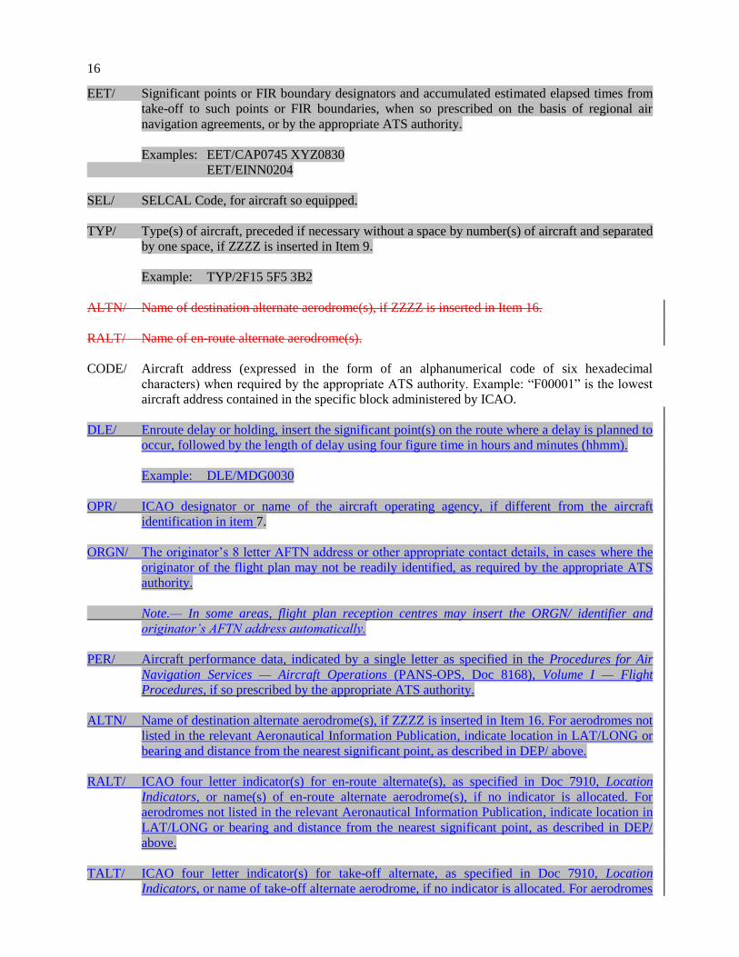
EET/ Significant points or FIR boundary designators and accumulated estimated elapsed times from
take-off to such points or FIR boundaries, when so prescribed on the basis of regional air
navigation agreements, or by the appropriate ATS authority.
Examples: EET/CAP0745 XYZ0830
EET/EINN0204
SEL/ SELCAL Code, for aircraft so equipped.
TYP/ Type(s) of aircraft, preceded if necessary without a space by number(s) of aircraft and separated
by one space, if ZZZZ is inserted in Item 9.
Example: TYP/2F15 5F5 3B2
ALTN/ Name of destination alternate aerodrome(s), if ZZZZ is inserted in Item 16.
RALT/ Name of en-route alternate aerodrome(s).
CODE/ Aircraft address (expressed in the form of an alphanumerical code of six hexadecimal
characters) when required by the appropriate ATS authority. Example: “F00001” is the lowest
aircraft address contained in the specific block administered by ICAO.
DLE/ Enroute delay or holding, insert the significant point(s) on the route where a delay is planned to
occur, followed by the length of delay using four figure time in hours and minutes (hhmm).
Example: DLE/MDG0030
OPR/ ICAO designator or name of the aircraft operating agency, if different from the aircraft
identification in item 7.
ORGN/ The originator’s 8 letter AFTN address or other appropriate contact details, in cases where the
originator of the flight plan may not be readily identified, as required by the appropriate ATS
authority.
Note.— In some areas, flight plan reception centres may insert the ORGN/ identifier and
originator’s AFTN address automatically.
PER/ Aircraft performance data, indicated by a single letter as specified in the Procedures for Air
Navigation Services — Aircraft Operations (PANS-OPS, Doc 8168), Volume I — Flight
Procedures, if so prescribed by the appropriate ATS authority.
ALTN/ Name of destination alternate aerodrome(s), if ZZZZ is inserted in Item 16. For aerodromes not
listed in the relevant Aeronautical Information Publication, indicate location in LAT/LONG or
bearing and distance from the nearest significant point, as described in DEP/ above.
RALT/ ICAO four letter indicator(s) for en-route alternate(s), as specified in Doc 7910, Location
Indicators, or name(s) of en-route alternate aerodrome(s), if no indicator is allocated. For
aerodromes not listed in the relevant Aeronautical Information Publication, indicate location in
LAT/LONG or bearing and distance from the nearest significant point, as described in DEP/
above.
TALT/ ICAO four letter indicator(s) for take-off alternate, as specified in Doc 7910, Location
Indicators, or name of take-off alternate aerodrome, if no indicator is allocated. For aerodromes

17
not listed in the relevant Aeronautical Information Publication, indicate location in LAT/LONG
or bearing and distance from the nearest significant point, as described in DEP/ above.
RIF/ The route details to the revised destination aerodrome, following by the ICAO four-letter
location indicator of the aerodrome. The revised route is subject to reclearance in flight.
Examples: RIF/DTA HEC KLAX
RIF/ESP G94 CLA YPPH
RMK/ Any other plain language remarks when required by the appropriate ATS authority or deemed
necessary.
ITEM 19: SUPPLEMENTARY
INFORMATION
. . .
4. Instructions for the transmission of
a supplementary flight plan (SPL) message
Items to be transmitted
Transmit items as indicated hereunder, unless otherwise prescribed:
a) AFTN Priority Indicator, Addressee Indicators <<≡, Filing Time, Originator Indicator <<≡ and,
if necessary, specific identification of addressees and/or originator;
b) commencing with <<≡ (SPL:
all symbols and data in the unshaded areas of boxes 7, 13, 16 and 18, except that the ‘)’ at the
end of box 18 is not to be transmitted, and then the symbols in the unshaded area of box 19
down to and including the )<<≡ of box 19,
additional alignment functions as necessary to prevent the inclusion of more than 69 characters
in any line of Items 18 and 19. The alignment function is to be inserted only in lieu of a space,
so as not to break up a group of data,
letter shifts and figure shifts (not pre-printed on the form) as necessary;
c) the AFTN Ending, as described below:
End-of-Text Signal
a) one LETTER SHIFT
b) two CARRIAGE RETURNS, one LINE FEED
Page-feed Sequence
Seven LINE FEEDS
End-of-Message Signal

18
Four of the letter N.
. . .
7. Instructions for the completion of
the repetitive flight plan (RPL) listing form . . .
7.4 Instructions for insertion of RPL data
. . .
ITEM G: SUPPLEMENTARY DATA AT
INSERT name and appropriate contact details of contactentity where information normally provided
under Item 19 of the FPL is kept readily available and can be supplied without delay.
. . .

19
APPENDIX 3. AIR TRAFFIC SERVICES MESSAGES
1. Message contents, formats
and data conventions . . .
1.2 The standard types of field
. . .
The standard fields of data permitted in ATS messages are as shown in the following table. The numbers
in column 1 correspond with those in the reference table on page A3-30.
Field
type Data
3 Message type, number and reference data
5 Description of emergency
7
8
9
10
Aircraft identification and SSR Mode and Code
Flight rules and type of flight
Number and type of aircraft and wake
turbulence category
Equipment and capabilities
13
14
15
16
17
18
19
20
21
22
Departure aerodrome and time
Estimate data
Route
Destination aerodrome and total estimated
elapsed time, destination alternate aerodrome(s)
Arrival aerodrome and time
Other information
Supplementary information
Alerting search and rescue information
Radio failure information
Amendment
. . .
1.6 Data conventions
. . .
1.6.3 The expression of position or route
The following alternative data conventions shall be used for the expression of position or route:
a) from 2 to 7 characters, being the coded designator assigned to an ATS route to be flown;
b) from 2 to 5 characters, being the coded designator assigned to an en-route point;
20
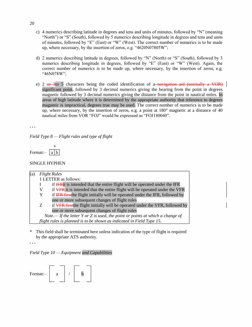
c) 4 numerics describing latitude in degrees and tens and units of minutes, followed by “N” (meaning
“North”) or “S” (South), followed by 5 numerics describing longitude in degrees and tens and units
of minutes, followed by “E” (East) or “W” (West). The correct number of numerics is to be made
up, where necessary, by the insertion of zeros, e.g. “4620N07805W”;
d) 2 numerics describing latitude in degrees, followed by “N” (North) or “S” (South), followed by 3
numerics describing longitude in degrees, followed by “E” (East) or “W” (West). Again, the
correct number of numerics is to be made up, where necessary, by the insertion of zeros, e.g.
“46N078W”;
e) 2 or 3to 5 characters being the coded identification of a navigation aid (normally a VOR)
significant point, followed by 3 decimal numerics giving the bearing from the point in degrees
magnetic followed by 3 decimal numerics giving the distance from the point in nautical miles. In
areas of high latitude where it is determined by the appropriate authority that reference to degrees
magnetic is impractical, degrees true may be used. The correct number of numerics is to be made
up, where necessary, by the insertion of zeros, e.g. a point at 180° magnetic at a distance of 40
nautical miles from VOR “FOJ” would be expressed as “FOJ180040”.
. . .
Field Type 8 — Flight rules and type of flight
*
Format:– a b
SINGLE HYPHEN
(a) Flight Rules
1 LETTER as follows:
I if IFRit is intended that the entire flight will be operated under the IFR
V if VFR it is intended that the entire flight will be operated under the VFR
Y if IFR firstthe flight initially will be operated under the IFR, followed by
one or more subsequent changes of flight rules
Z if VFR firstthe flight initially will be operated under the VFR, followed by
one or more subsequent changes of flight rules
Note.— If the letter Y or Z is used, the point or points at which a change of
flight rules is planned is to be shown as indicated in Field Type 15.
* This field shall be terminated here unless indication of the type of flight is required
by the appropriate ATS authority.
. . .
Field Type 10 — Equipment and Capabilities
Format:– a / b

21
SINGLE HYPHEN
(a) Radio Communication, Navigation and Approach Aid Equipment and Capabilities
1 LETTER as follows:
N no COM/NAV/approach aid equipment for the route to be flown is carried, or
the equipment is unserviceable
OR S Standard COM/NAV/approach aid equipment for the route to be flown is carried
and serviceable (See Note 1)
AND/OR ONE OR MORE OF THE FOLLOWING LETTERS to indicate the serviceable
COM/NAV/approach aid equipment serviceableand capabilities
A
B
C
D
E1
E2
E3
F
G
H
I
J1
J2
J3
J4
J5
J6
(Not allocated)GBAS landing
system
(Not allocated)LPV (APV with
SBAS)
LORAN C
DME
(Not allocated)FMC WPR
ACARS
D-FIS ACARS
PDC ACARS
ADF
(GNSS) (See Note 2)
HF RTF
Inertial Navigation
(Data link)CPDLC ATN VDL
Mode 2 (see Note 3)
CPDLC FANS 1/A HFDL
CPDLC FANS 1/A VDL
Mode 4
CPDLC FANS 1/A VDL
Mode 2
CPDLC FANS 1/A SATCOM
(INMARSAT)
CPDLC FANS 1/A SATCOM
(MTSAT)
J7
K
L
M1
M2
M3
O
P1–P9
Q
R
T
U
V
W
X
Y
Z
CPDLC FANS 1/A SATCOM
(Iridium)
(MLS)
ILS
OmegaATC RTF SATCOM
(INMARSAT)
ATC RTF (MTSAT)
ATC RTF (Iridium)
VOR
(Not allocated)Reserved for RCP
(Not allocated)
RNP type certificationPBN approved
(see Note 54)
TACAN
UHF RTF
VHF RTF
RVSM approved
MNPS approved
when prescribed by ATSVHF with
8.33 kHz channel spacing capability
Other equipment carried or other
capabilities (see Note 25)
Note 1.— If the letter S is used, sStandard equipment is considered to be VHF RTF, ADF,
VOR and ILS, unless another combination is prescribed by the appropriate ATS authority.
Note 2.— If the letter G is used, the types of external GNSS augmentation, if any, are
specified in Item 18 following the indicator NAV/ separated by a space.
Note 25.— If the letter Z is used, specify in Item 18 the other the equipment carried or
other capabilitiesis to be specified in Item 18, preceded by COM/ , and/or NAV/ and/or
DAT, as appropriate.
Note 3.— If the letter J is used, specify in Item 18 the equipment carried, preceded by DAT/
followed by one or more letters as appropriate.See RTCA/EUROCAE Interoperability
Requirements Standard For ATN Baseline 1 (ATN B1 INTEROP Standard – DO-
280B/ED-110B) for data link services air traffic control clearance and information/air
traffic control communications management/air traffic control microphone check.

22
Note 46.— Information on navigation capability is provided to ATC for clearance and
routing purposes.
Note 54.— Inclusion ofIf the letter R is used, the performance based navigation levels that
can be met are specified in Item 18 following the indicator PBN/. Guidance material on the
application of performance-based navigation to a specific indicates that an aircraft meets
the RNP type prescribed for the route segment(s), route(s) and/or area concerned is
contained in the Performance-Based Navigation Manual (Doc 9613).
OBLIQUE STROKE
(b) Surveillance Equipment and capabilities
INSERT N if no surveillance equipment for the route to be flown is carried, or the
equipment is unserviceable,
OR
ONE OR TWO LETTERSMORE of the following descriptors, to a maximum of 20
characters, to describe the serviceable surveillance equipment carriedand/or capabilities
on board:
SSR equipmentModes A and C
N Nil
A Transponder — Mode A (4 digits — 4 096 codes)
C Transponder — Mode A (4 digits — 4 096 codes) and Mode C
SSR Mode S
X Transponder — Mode S without both aircraft identification and pressure-altitude
transmission
E Transponder — Mode S, including aircraft identification, pressure-altitude and
extended squitter (ADS-B) capability
H Transponder — Mode S, including aircraft identification, pressure-altitude and
enhanced surveillance capability
I Transponder — Mode S, including aircraft identification, but no pressure-altitude
capability
L Transponder — Mode S, including aircraft identification, pressure-altitude,
extended squitter (ADS-B) and enhanced surveillance capability
P Transponder — Mode S, including pressure-altitude, but no aircraft identification
transmissioncapability
I Transponder — Mode S, including aircraft identification transmission, but no
pressure-altitude transmission
S Transponder — Mode S, including both pressure altitude and aircraft identification
transmissioncapability
X Transponder — Mode S with neither aircraft identification nor pressure-altitude
capability
Note.– Enhanced surveillance capability is the ability of the aircraft to down-link
aircraft derived data via a Mode S transponder.

23
ADS-B
B1 ADS-B with dedicated 1090 MHz ADS-B “out” capability
B2 ADS-B with dedicated 1090 MHz ADS-B “out” and “in” capability
U1 ADS-B “out” capability using UAT
U2 ADS-B “out” and “in” capability using UAT
V1 ADS-B “out” capability using VDL Mode 4
V2 ADS-B “out” and “in” capability using VDL Mode 4
ADS-C
D1 ADS-C with FANS 1/A capabilities
G1 ADS-C with ATN capabilities
ADS equipment
D ADS capability
Alphanumeric characters not indicated above are reserved.
Note.– Additional surveillance application should be listed in Item 18 following the
indicator SUR/ .
Examples: –S/A
–SCHJI/CDB1
–SAFJR/SDV1
. . .
Field Type 13 — Departure aerodrome and time
*
Format:– a b
SINGLE HYPHEN
(a) Departure Aerodrome
4 LETTERS, being
the ICAO four-letter location indicator allocated to the departure
aerodrome as specified in Doc 7910, Location Indicators, or
ZZZZ if no ICAO location indicator has been allocated (see Note 1) or if
the departure aerodrome is not known, or
AFIL if the flight plan has been filed in the air (see Note 2).
Note 1.— If ZZZZ is used, the name and location of the departure
aerodrome is to be shown in the Other Information Field (see Field Type

24
18) if this Field Type is contained in the message.
Note 2.— If AFIL is used, the ATS unit from which supplementary flight
data can be obtained is to be shown in the Other Information Field (Field
Type 18).
* This field shall be terminated here in message types CHG, CNL, ARR, CPL,
EST, CDN, and ACP and RQS. It shall be terminated here in message type
RQP if the estimated off-block time is not known.
(b) Time
4 NUMERICS giving
the estimated off-block time (EOBT) at the aerodrome in (a) in FPL, ARR,
CHG, CNL, and DLA and RQS messages transmitted before departure and
in RQP message, if known, or
the actual time of departure from the aerodrome in (a) in ALR, DEP and
SPL messages, or
the actual or estimated time of departure from the first point shown in the
Route Field (see Field Type 15) in FPL messages derived from flight plans
filed in the air, as shown by the letters AFIL in (a).
Examples: –EHAM0730
–AFIL1625
. . .
Field Type 14 — Estimate data
*
Format:– a / b c d e
SINGLE HYPHEN
(a) Boundary Point (see Note 1)
The BOUNDARY POINT expressed either by a designator consisting
of 2 to 5 characters, in Geographical Coordinates, in Abbreviated
Geographical Coordinates, or by bearing and distance from a
designatedsignificant point (e.g. a VOR).
Note 1.— This point may be an agreed point located close to,
rather than on, the FIR boundary.
Note 2.— See 1.6 for data conventions.
. . .

25
Field Type 16 — Destination aerodrome and total estimated
Field Type 16 — elapsed time, destination alternate aerodrome(s)
* **
Format:– a b (sp) c
See Note in margin
on page A3-201.
FIELD TYPE 16
Previous
type of
field or
symbol
This type
of field
is used in
Next type
of field
or
symbol
15 ALR 18
15
13
13
13
13
13
FPL
CHG
CNL
DLA
DEP
ARR***
18
2218
)18
)18
)18
17
15
14
13
13
CPL
EST
CDN
ACP
18
)
22
)
13
13
13
RQP
RQS
SPL
18
)18
18
*** Only in case of a
diversionary landing.
SINGLE HYPHEN
(a) Destination Aerodrome
4 LETTERS, being
the ICAO four-letter location indicator allocated to the destination
aerodrome as specified in Doc 7910, Location Indicators, or
ZZZZ if no ICAO location indicator has been allocated.
Note.— If ZZZZ is used, the name and location of the destination
aerodrome is to be shown in the Other Information Field (see Field
Type 18).
* This field is to be terminated here in all message types other than ALR,
FPL and SPL.

26
. . .
SPACE
(c) Destination Alternate Aerodrome(s) .
4 LETTERS, being
the ICAO four-letter location indicator allocated to an
alternate aerodrome, as specified in Doc 7910, Location
Indicators or
Note.— One further element of (c) should be
added, as necessary, preceded by a space
ZZZZ if no ICAO location indicator has been allocated.
Note.— If ZZZZ is used, the name and location of the
destination alternate aerodrome is to be shown in the
Other Information Field (see Field Type 18).
Examples: –EINN0630
–EHAM0645 EBBR
–EHAM0645 EBBR EDDL
Field Type 17 — Arrival aerodrome and time
*
Format:– a b (sp) c
SINGLE HYPHEN
(a) Arrival Aerodrome
4 LETTERS, being
the ICAO four-letter location indicator allocated to the arrival
aerodrome as specified in Doc 7910, Location Indicators, or
ZZZZ if no ICAO location indicator has been allocated.
(b)
Time of Arrival
4 NUMERICS, giving
the actual time of arrival.
* This field is to be terminated here if an ICAO location indicator has
been allocated to the arrival aerodrome.
. . .

27
Field Type 18 — Other information
Note.— Use of indicators not included under this item may result in data being rejected, processed
incorrectly or lost.
Hyphens or oblique strokes should only be used as prescribed below.
Format:– a
or
Format:– (sp) (sp) * (sp)
(* additional elements as necessary)
SINGLE HYPHEN
(a) 0 (zero) if no other information,
OR,
Any other necessary information in the preferred sequence shown hereunder, in the form of the
appropriate indicator selected from those defined hereunder followed by an oblique stroke and the
information to be recorded:
STS/ Reason for special handling by ATS, e.g. a search and rescue mission, as follows:
ALTRV: for a flight operated in accordance with an altitude reservation;
ATFMX: for a flight approved for exemption from ATFM measures by the appropriate ATS
authority;
FFR: fire-fighting;
FLTCK: flight check for calibration of navaids;
HAZMAT: for a flight carrying hazardous material;
HEAD: a flight with Head of State status;
HOSP: for a medical flight declared by medical authorities;
HUM: for a flight operating on a humanitarian mission;
MARSA: for a flight for which a military entity assumes responsibility for separation of
military aircraft;
MEDEVAC: for a life critical medical emergency evacuation;
NONRVSM: for a non-RVSM capable flight intending to operate in RVSM airspace;
SAR: for a flight engaged in a search and rescue mission; and
STATE: for a flight engaged in military, customs or police services.
Other reasons for special handling by ATS shall be denoted under the designator RMK/.
PBN/ Indication of RNAV and/or RNP capabilities. Include as many of the descriptors below, as
apply to the flight, up to a maximum of 8 entries, i.e. a total of not more than 16 characters.

28
RNAV SPECIFICATIONS
A1 RNAV10 (RNP 10)
B1 RNAV 5 all permitted sensors
B2 RNAV 5 GNSS
B3 RNAV 5 DME/DME
B4 RNAV 5 VOR/DME
B5 RNAV 5 INS or IRS
B6 RNAV 5 LORANC
C1 RNAV 2 all permitted sensors
C2 RNAV 2 GNSS
C3 RNAV 2 DME/DME
C4 RNAV 2 DME/DME/IRU
D1 RNAV 1 all permitted sensors
D2 RNAV 1 GNSS
D3 RNAV 1 DME/DME
D4 RNAV 1 DME/DME/IRU
RNP SPECIFICATIONS
L1 RNP 4
O1 Basic RNP 1 all permitted sensors
O2 Basic RNP 1 GNSS
O3 Basic RNP 1 DME/DME
O4 Basic RNP 1 DME/DME/IRU
S1 RNP APCH
S2 RNP APCH with BAR-VNAV
T1 RNP AR APCH with RF (special authorization required)
T2 RNP AR APCH without RF (special authorization required)
Combinations of alphanumeric characters not indicated above are reserved.
EET/ Significant points or FIR boundary designators and accumulated estimated elapsed times to
such points or FIR boundaries, when so prescribed on the basis of regional air navigation
agreements, or by the appropriate ATS authority.
Examples: EET/CAP0745 XYZ0830
EET/EINN0204
RIF/ The route details to the revised destination aerodrome, followed by the ICAO four-letter
location indicator of the aerodrome. The revised route is subject to reclearance in flight.
Examples: RIF/DTA HEC KLAX
Examples: RIF/ESP G94 CLA YPPH
Examples: RIF/LEMD

29
REG/ The registration markings of the aircraft, if different from the aircraft identification in Item 7.
SEL/ SELCAL Code, if so prescribed by the appropriate ATS authority.
OPR/ Name of the operator, if not obvious from the aircraft identification in Item 7.
STS/ Reason for special handling by ATS, e.g. hospital aircraft, one engine inoperative, e.g.
STS/HOSP, STS/ONE ENG INOP.
TYP/ Type(s) of aircraft, preceded if necessary by number(s) of aircraft, if ZZZZ is inserted in
Item 9.
PER/ Aircraft performance data, if so prescribed by the appropriate ATS authority.
COM/ Significant data related to communication equipment as required by the appropriate ATS
authority, e.g. COM/UHF only.
DAT/ Significant data related to data link capability, using one or more of the letters S, H, V and M,
e.g. DAT/S for satellite data link, DAT/H for HF data link, DAT/V for VHF data link, DAT/M
for SSR Mode S data link.
NAV/ Significant data related to navigation equipment, other than specified in PBN/, as required by
the appropriate ATS authority. Indicate GNSS augmentation under this indicator, with a space
between two or more methods of augmentation, e.g. NAV/GBAS SBAS.
COM/ Indicate communications applications or capabilities not specified in Item 10a.
DAT/ Indicate data applications or capabilities not specified in Item 10a.
SUR/ Include surveillance applications or capabilities not specified in Item 10b.
DEP/ Name and location of departure aerodrome, if ZZZZ is inserted in Item 13, or the ICAO four-
letter location indicator of the location of the ATS unit from which supplementary flight plan
data can be obtained, if AFIL is inserted in Item 13. For aerodromes not listed in the relevant
Aeronautical Information Publication, indicate location as follows:
With 4 figures describing latitude in degrees and tens and units of minutes followed by “N”
(North) or “S” (South), followed by 5 figures describing longitude in degrees and tens and units
of minutes, followed by “E” (East) or “W” (West). Make up the correct number of figures,
where necessary, by insertion of zeros, e.g. 4620N07805W (11 characters).
OR Bearing and distance from the nearest significant point, as follows:
The identification of the significant point followed by the bearing from the point in the form of
3 figures giving degrees magnetic, followed by the distance from the point in the form of 3
figures expressing nautical miles. In areas of high latitude where it is determined by the
appropriate authority that reference to degrees magnetic is impractical, degrees true may be
used. Make up the correct number of figures, where necessary, by insertion of zeros, e.g. a
point of 180° magnetic at a distance of 40 nautical miles from VOR “DUB” should be
expressed as DUB180040.

30
OR The first point of the route (name or LAT/LONG) or the marker radio beacon, if the aircraft has
not taken off from an aerodrome.
DEST/ Name and location of destination aerodrome, if ZZZZ is inserted in Item 16. For aerodromes
not listed in the relevant Aeronautical Information Publication, indicate location in LAT/LONG
or bearing and distance from the nearest significant point, as described under DEP/ above.
DOF/ The date of flight departure in a six figure format (YYMMDD, where YY equals the year, MM
equals the month and DD equals the day).
REG/ The nationality or common mark and registration mark of the aircraft, if different from the
aircraft identification in Item 7.
EET/ Significant points or FIR boundary designators and accumulated estimated elapsed times from
take-off to such points or FIR boundaries, when so prescribed on the basis of regional air
navigation agreements, or by the appropriate ATS authority.
Examples: EET/CAP0745 XYZ0830
EET/EINN0204
SEL/ SELCAL Code, for aircraft so equipped.
TYP/ Type(s) of aircraft preceded if necessary without a space by number(s) of aircraft and separated
by one space if ZZZZ is inserted in Item 9.
Example: –TYP/2F15 5F5 3B2
ALTN/ Name of destination alternate aerodrome(s), if ZZZZ is inserted in Item 16.
RALT/ Name of en-route alternate aerodrome(s).
CODE/ Aircraft address (expressed in the form of an alphanumerical code of six hexadecimal
characters) when required by the appropriate ATS authority. Example: “F00001” is the lowest
aircraft address contained in the specific block administered by ICAO.
DLE/ Enroute delay or holding, insert the significant point(s) on the route where a delay is planned to
occur, followed by the length of delay using four figure time in hours and minutes (hhmm).
Example: –DLE/MDG0030
OPR/ ICAO designator or name of the aircraft operating agency, if different from the aircraft
identification in item 7.
ORGN/ The originator’s 8 letter AFTN address or other appropriate contact details, in cases where the
originator of the flight plan may not be readily identified, as required by the appropriate ATS
authority.
Note.— In some areas, flight plan reception centres may insert the ORGN/ identifier and
originator’s AFTN address automatically.

31
PER/ Aircraft performance data, indicated by a single letter as specified in the Procedures for Air
Navigation Services — Aircraft Operations (PANS-OPS, Doc 8168), Volume I — Flight
Procedures, if so prescribed by the appropriate ATS authority.
ALTN/ Name of destination alternate aerodrome(s), if ZZZZ is inserted in Item 16. For aerodromes not
listed in the relevant Aeronautical Information Publication, indicate location in LAT/LONG or
bearing and distance from the nearest significant point, as described in DEP/ above.
RALT/ ICAO four letter indicator(s) for en-route alternate(s), as specified in Doc 7910, Location
Indicators, or name(s) of en-route alternate aerodrome(s), if no indicator is allocated. For
aerodromes not listed in the relevant Aeronautical Information Publication, indicate location in
LAT/LONG or bearing and distance from the nearest significant point, as described in DEP/
above.
TALT/ ICAO four letter indicator(s) for take-off alternate, as specified in Doc 7910, Location
Indicators, or name of take-off alternate aerodrome, if no indicator is allocated. For aerodromes
not listed in the relevant Aeronautical Information Publication, indicate location in LAT/LONG
or bearing and distance from the nearest significant point, as described in DEP/ above.
RIF/ The route details to the revised destination aerodrome, following by the ICAO four-letter
location indicator of the aerodrome. The revised route is subject to reclearance in flight.
Examples:–RIF/DTA HEC KLAX
–RIF/ESP G94 CLA YPPH
RMK/ Any other plain language remarks when required by the appropriate ATS authority or deemed
necessary.
Examples:–0
–STS/MEDEVAC
–EET/015W0315 020W0337 030W0420 040W0502
–STS/ONE ENG INOP
–DAT/S
. . .
Field Type 22 — Amendment
FIELD TYPE 22
Previous
type of
field or
symbol
This type
of field
is used in
Next type
of field
or
symbol
1618 CHG *22 or)
16 CDN *22 or)
* Indicates that further fields of
this type may be added
. . .

32
RULES FOR THE COMPOSITION OF ATS MESSAGES
(See Sections 1.3 to 1.8 of this Appendix)
. . .
STANDARD ATS MESSAGES AND THEIR COMPOSITION
DESIGNATOR
. . .
. . .
Other
information
MESSAGE TYPE 18
Alerting ALR
Radiocommunication failure RCF
Filed flight plan FPL
Delay DLA 18
Modification CHG 18
Flight plan cancellation CNL 18
Departure DEP 18
Arrival ARR
Current flight plan CPL
Estimate EST
Coordination CDN
Acceptance ACP
Logical acknowledgement message LAM
Request flight plan RQP 18
Request supplementary flight plan RQS 18
Supplementary flight plan SPL
. . .
The expression of position or route
The following alternative data conventions shall be used for the expression of position or route:
. . .
(e) 2 or 3to 5 characters being the coded identification of a navigation aid (normally a VOR)
significant point, followed by 3 decimal numerics giving the bearing from the point in degrees
magnetic followed by 3 decimal numerics giving the distance from the point in nautical miles. In
areas of high latitude where it is determined by the appropriate authority that reference to degrees
magnetic is impractical, degrees true may be used. The correct number of numerics is to be made
up, where necessary, by insertion of zeros, e.g. a point at 180° magnetic at a distance of 40
nautical miles from VOR “FOJ” would be expressed as “FOJ180040”.
. . .

33
2. Examples of ATS messages
. . .
2.2 Emergency messages
2.2.1 Alerting (ALR) message
2.2.1.1 Composition
. . .
– 9
Type of aircraft and
wake turbulence category
–
10
Equipment and capabilities
. . .
16
Destination aerodrome and total estimated elapsed time, destination alternate
aerodrome(s)
. . .
2.2.1.2 Example
The following is an example of an alerting message relating to an uncertainty phase, sent by Athens
Approach Control to Belgrade Centre and other ATS units, in respect of a flight from Athens to Munich.
(ALR-INCERFA/LGGGZAZX/OVERDUE
–FOX236/A360024-IM
–C141/H-S/CD
–LGAT1020
–N0430F220 B9 3910N02230W/N0415F240 B9 IVA/N0415F180 B9
–EDDM0227 EDDF
–REG/A43213 EET/LYBE0020 EDMI0133 REG/A43213 OPR/USAF RMK/NO
POSITION REPORT SINCE DEP PLUS 2 MINUTES
–E/0720 P/12 R/UV J/LF D/02 014 C ORANGE A/SILVER C/SIGGAH
–USAF LGGGZAZX 1022 126.7 GN 1022 PILOT REPORT OVER NDB ATS
UNITS ATHENS FIR ALERTED NIL)
2.2.1.2.1 Meaning
Alerting message — uncertainty phase declared by Athens due no position reports and no radio contact
since two minutes after departure — aircraft identification FOX236 — IFR, military flight — Starlifter,
heavy wake turbulence category, equipped with standard communications, navigation and approach aid
equipment for the route, SSR transponder with Modes A (4 096 code capability) and C — ADS capability
— last assigned Code 3624 — departed Athens 1020 UTC — cruising speed for first portion of route 430
knots, first requested cruising level FL 220 — proceeding on airway Blue 9 to 3910N2230W where TAS
would be changed to 415 knots and FL240 would be requested — proceeding on airway Blue 9 to Ivanic
Grad VOR where FL 180 would be requested, maintaining TAS of 415 knots and FL240 would be
requested — proceeding on airway Blue 9 to Munich, total estimated elapsed time 2 hours and 27 minutes
— destination alternate is Frankfurt — aircraft registration A43213 — accumulated estimated elapsed

34
times at the Belgrade and Munich FIR boundaries 20 minutes and 1 hour and 33 minutes respectively —
aircraft registration A43213 — the aircraft is operated by the USAF — no position report has been
received since 2 minutes after departure — endurance 7 hours and 20 minutes after take-off — 12 persons
on board — portable radio equipment working on VHF 121.5 MHz and UHF 243 MHz is carried — life
jackets fitted with lights and fluorescein are carried — 2 dinghies with orange covers are carried, have a
total capacity for 14 persons — aircraft colour is silver — pilot’s name is SIGGAH — operator is USAF
— Athens approach control was the last unit to make contact at 1022 UTC on 126.7 MHz when pilot
reported over GN runway locator beacon — Athens approach control have alerted all ATS units within
Athens FIR — no other pertinent information.
. . .
2.3 Filed flight plan and associated update messages
2.3.1 Filed flight plan (FPL) message
2.3.1.1 Composition
( 3
Message type, number
and reference data
–
7
Aircraft identification and
SSR Mode and Code
–
8
Flight rules and
type of flight
– 9
Type of aircraft and
wake turbulence category
–
10
Equipment and capabilities
– 13
Departure aerodrome
and time
– 15
Route (using more than one line if necessary)
– 16
Destination aerodrome and total estimated elapsed time, destination alternate
aerodrome(s)
– 18
Other information (using more than one line if necessary)
)
2.3.1.2 Example
The following is an example of a filed flight plan message sent by London Airport to Shannon, Shanwick
and Gander Centres. The message may also be sent to the London Centre or the data may be passed to
that centre by voice.
(FPL-TPRACA101-IS
–B707MB773/H-CHOPV/CD
–EGLL1400
–N0450F310 G1 UG1L9 UL9 STU285036/M082F310 UG1UL9 52N015WLIMRI
35
52N020W 52N030W 50N040W 49N050W
–CYQX0455 CYYR
–EET/EISNN0026 EGGX0111 020W0136 CYQX0228 040W0330 050W0415 SEL/FJEL)
2.3.1.2.1 Meaning
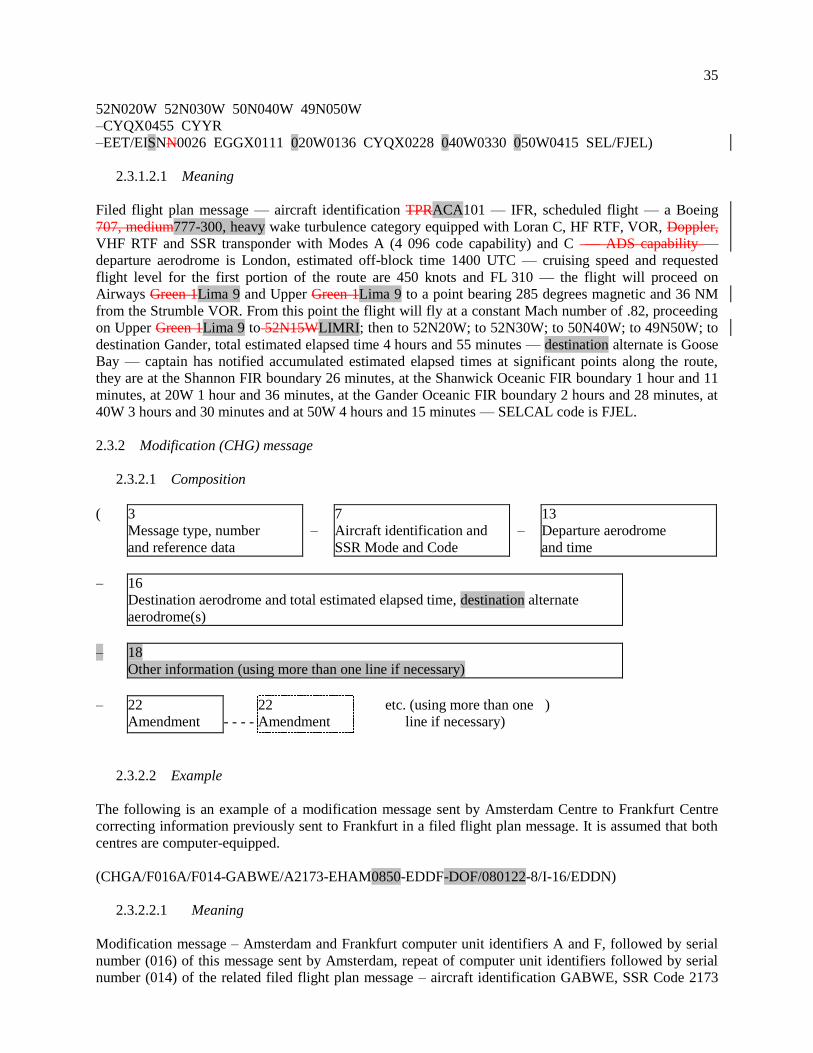
Filed flight plan message — aircraft identification TPRACA101 — IFR, scheduled flight — a Boeing
707, medium777-300, heavy wake turbulence category equipped with Loran C, HF RTF, VOR, Doppler,
VHF RTF and SSR transponder with Modes A (4 096 code capability) and C — ADS capability —
departure aerodrome is London, estimated off-block time 1400 UTC — cruising speed and requested
flight level for the first portion of the route are 450 knots and FL 310 — the flight will proceed on
Airways Green 1Lima 9 and Upper Green 1Lima 9 to a point bearing 285 degrees magnetic and 36 NM
from the Strumble VOR. From this point the flight will fly at a constant Mach number of .82, proceeding
on Upper Green 1Lima 9 to 52N15WLIMRI; then to 52N20W; to 52N30W; to 50N40W; to 49N50W; to
destination Gander, total estimated elapsed time 4 hours and 55 minutes — destination alternate is Goose
Bay — captain has notified accumulated estimated elapsed times at significant points along the route,
they are at the Shannon FIR boundary 26 minutes, at the Shanwick Oceanic FIR boundary 1 hour and 11
minutes, at 20W 1 hour and 36 minutes, at the Gander Oceanic FIR boundary 2 hours and 28 minutes, at
40W 3 hours and 30 minutes and at 50W 4 hours and 15 minutes — SELCAL code is FJEL.
2.3.2 Modification (CHG) message
2.3.2.1 Composition
( 3
Message type, number
and reference data
–
7
Aircraft identification and
SSR Mode and Code
–
13
Departure aerodrome
and time
– 16
Destination aerodrome and total estimated elapsed time, destination alternate
aerodrome(s)
– 18
Other information (using more than one line if necessary)
– 22
Amendment
- - - -
22
Amendment
etc. (using more than one
line if necessary)
)
2.3.2.2 Example
The following is an example of a modification message sent by Amsterdam Centre to Frankfurt Centre
correcting information previously sent to Frankfurt in a filed flight plan message. It is assumed that both
centres are computer-equipped.
(CHGA/F016A/F014-GABWE/A2173-EHAM0850-EDDF-DOF/080122-8/I-16/EDDN)
2.3.2.2.1 Meaning
Modification message – Amsterdam and Frankfurt computer unit identifiers A and F, followed by serial
number (016) of this message sent by Amsterdam, repeat of computer unit identifiers followed by serial
number (014) of the related filed flight plan message – aircraft identification GABWE, SSR Code 2173

36
operating in Mode A, en route from Amsterdam EOBT0850 to Frankfurt date of flight 22 Jan 2008 –
Field Type 8 of the related filed flight plan message is corrected to IFR – Field Type 16 of the related
filed flight plan is corrected, the new destination is Nürnberg.
2.3.3 Flight plan cancellation (CNL) message
2.3.3.1 Composition
( 3
Message type, number
and reference data
–
7
Aircraft identification and
SSR Mode and Code
–
13
Departure aerodrome
and time
– 16
Destination aerodrome and total estimated elapsed time, destination alternate
aerodrome(s)
)
– 18
Other information (using more than one line if necessary)
)
2.3.3.2 Example 1
The following is an example of a flight plan cancellation message sent by an ATS unit to all addressees of
a filed flight plan message previously sent by that unit.
(CNL-DLH522-EDBB0900-LFPO-0)
2.3.3.2.1 Meaning
Flight plan cancellation message – cancel the flight plan of aircraft identification DLH522 – flight
planned from Berlin EOBT0900 to Paris – no other information.
2.3.3.3 Example 2
The following is an example of a flight plan cancellation message sent by a centre to an adjacent centre. It
is assumed that both centres are equipped with ATC computers.
(CNLF/B127F/B055-BAW580-EDDF1430-EDDW-0)
2.3.3.3.1 Meaning
Flight plan cancellation message – identifiers of sending and receiving ATC computer units F and B,
followed by serial number (127) of this message, repeat of computer unit identifiers followed by serial
number (055) of current flight plan message previously transmitted – cancel the flight plan of aircraft
identification BAW580 – flight planned from Frankfurt EOBT1430 to Bremen – no other information.
2.3.4 Delay (DLA) message
2.3.4.1 Composition
( 3
Message type, number
and reference data
–
7
Aircraft identification and
SSR Mode and Code
–
13
Departure aerodrome
and time
37
– 16
Destination aerodrome and total estimated elapsed time, destination alternate
aerodrome(s)
)
– 18
Other information (using more than one line if necessary)
)
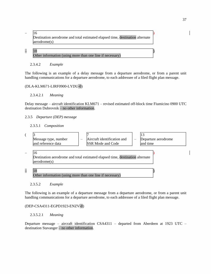
2.3.4.2 Example
The following is an example of a delay message from a departure aerodrome, or from a parent unit
handling communications for a departure aerodrome, to each addressee of a filed flight plan message.
(DLA-KLM671-LIRF0900-LYDU-0)
2.3.4.2.1 Meaning
Delay message – aircraft identification KLM671 – revised estimated off-block time Fiumicino 0900 UTC
destination Dubrovnik – no other information.
2.3.5 Departure (DEP) message
2.3.5.1 Composition
( 3
Message type, number
and reference data
–
7
Aircraft identification and
SSR Mode and Code
–
13
Departure aerodrome
and time
– 16
Destination aerodrome and total estimated elapsed time, destination alternate
aerodrome(s)
)
– 18
Other information (using more than one line if necessary)
)
2.3.5.2 Example
The following is an example of a departure message from a departure aerodrome, or from a parent unit
handling communications for a departure aerodrome, to each addressee of a filed flight plan message.
(DEP-CSA4311-EGPD1923-ENZV-0)
2.3.5.2.1 Meaning
Departure message – aircraft identification CSA4311 – departed from Aberdeen at 1923 UTC –
destination Stavanger – no other information.

38
2.3.6 Arrival (ARR) message
2.3.6.1 Composition
( 3
Message type, number
and reference data
–
7
Aircraft identification and
SSR Mode and Code
–
13
Departure aerodrome
and time
– 17
Arrival aerodrome and time
)
2.3.6.2 Example 1
The following is an example of an arrival message sent from the arrival aerodrome (= destination) to the
departure aerodrome.
(ARR-CSA406-LHBP0800-LKPR0913)
2.3.6.2.1 Meaning
Arrival message — aircraft identification CSA406 — departed from Budapest/Ferihegy at 0800 — landed
at Prague/Ruzyne Airport at 0913 UTC.
2.3.6.3 Example 2
The following is an example of an arrival message sent for an aircraft which has landed at an aerodrome
for which no ICAO location indicator has been allocated. The SSR Code would not be meaningful.
(ARR-HELI13HHE13-EHAM-10300900 – EDDD – ZZZZ1030 DEN HELDER)
2.3.6.3.1 Meaning
Arrival message aircraft identification HELI13HHE13 — departed from Amsterdam at 0900 —
destination Frankfurt – landed at Den Helder heliport at 1030 UTC.
2.4 Coordination messages
2.4.1 Current flight plan (CPL) message
2.4.1.1 Composition
( 3
Message type, number
and reference data
–
7
Aircraft identification and
SSR Mode and Code
–
8
Flight rules and
type of flight
– 9
Type of aircraft and
wake turbulence category
–
10
Equipment and capabilities
– 13
Departure aerodrome
and time
–
14
Estimate data

39
– 15
Route (using more than one line if necessary)
– 16
Destination aerodrome and total estimated elapsed time, destination alternate
aerodrome(s)
– 18
Other information (using more than one line if necessary)
)
2.4.1.2 Example 1
The following is an example of a current flight plan message sent from Boston Centre to New York
Centre on a flight which is en route from Boston to La Guardia Airport.
(CPL-UAL621/A5120-IS
–DC9A320/M-S/CD
–KBOS-HFD/1341A220A200A
–N0420A220 V3 AGL V445
–KLGA
–0)
2.4.1.3 Example 2
The following is an example of the same current flight plan message, but in this case the message is
exchanged between ATC computers.
(CPLBOS/LGA052-UAL621/A5120-IS
–DC9A320/M-S/CD
–KBOS-HFD/1341A220A200A
–N0420A220 V3 AGL V445
–KLGA
–0)
Note.— The messages in Examples 1 and 2 are identical except that the Message Number of
Example 2 does not appear in Example 1.
2.4.1.4 Meaning
Current flight plan message [with sending unit identity (BOS) and receiving unit identity (LGA),
followed by the serial number of this message (052)] — aircraft identification UAL621, last assigned
SSR Code 5120 in Mode A — IFR, scheduled flight — one DC9A320, medium wake turbulence
category, equipped with standard communications, navigation and approach aid equipment for the route
and SSR transponder with Modes A (4 096 code capability) and C — ADS capability — departed Boston
— the flight is estimated to cross the Boston/New York “boundary” at point HFD at 1341 UTC, cleared
by the Boston Centre at altitude 22 000 feet but to be at or above altitude 20 000 feet at HFD — TAS is
420 knots, requested cruising level is altitude 22 000 feet — the flight will proceed on airway V3 to
reporting point AGL thence on airway V445 — destination is La Guardia Airport — no other
information.

40
2.4.2 Estimate (EST) message
2.4.2.1 Composition
( 3
Message type, number
and reference data
–
7
Aircraft identification and
SSR Mode and Code
–
13
Departure aerodrome
and time
– 14
Estimate data
–
16
Destination aerodrome and total estimated elapsed time,
destination alternate aerodrome(s)
)
. . .
2.4.3 Coordination (CDN) message
2.4.3.1 Composition
( 3
Message type, number
and reference data
–
7
Aircraft identification and
SSR Mode and Code
–
13
Departure aerodrome
and time
– 16
Destination aerodrome and total estimated elapsed time, destination alternate
aerodrome(s)
– 22
Amendment
- - - -
22
Amendment
etc. (using more than one
line if necessary)
)
. . .
2.4.4 Acceptance (ACP) message
2.4.4.1 Composition
( 3
Message type, number
and reference data
–
7
Aircraft identification and
SSR Mode and Code
–
13
Departure aerodrome
and time
– 16
Destination aerodrome and total estimated elapsed time, destination alternate
aerodrome(s)
)
. . .

41
2.5 Supplementary messages
2.5.1 Request flight plan (RQP) message
2.5.1.1 Composition
( 3
Message type, number
and reference data
–
7
Aircraft identification and
SSR Mode and Code
– 13
Departure aerodrome
and time
–
16
Destination aerodrome and total estimated elapsed time,
destination alternate aerodrome(s)
)
– 18
Other information (using more than one line if necessary)
)
2.5.1.2 Example
The following is an example of a request flight plan message sent by a centre to an adjacent centre after
receipt of an estimate message, for which no corresponding filed flight plan message had been received
previously.
(RQP-PHOEN-EHRD-EDDL-0)
2.5.1.2.1 Meaning
Request flight plan message – aircraft identification PHOEN departed from Rotterdam – destination
Düsseldorf – no other information.
2.5.2 Request supplementary flight plan (RQS) message
2.5.2.1 Composition
( 3
Message type, number
and reference data
–
7
Aircraft identification and
SSR Mode and Code
–
13
Departure aerodrome
and time
– 16
Destination aerodrome and total estimated elapsed time, destination alternate
aerodrome(s)
)
– 18
Other information (using more than one line if necessary)
)
2.5.2.2 Example
The following is an example of a request flight plan message sent by an ATS unit to the ATS unit serving
the departure aerodrome requesting information contain in the flight plan form, but not transmitted in the
filed or current filed flight plan messages.
(RQS-KLM405/A4046-EHAM-CYMX-0)

42
2.5.2.2.1 Meaning
Request supplementary flight plan message – aircraft identification KLM405/SSR Code 4046 operating
in Mode A – departure aerodrome is Amsterdam – destination aerodrome is Mirabel – no other
information.
2.5.3 Supplementary flight plan (SPL) message
2.5.3.1 Composition
( 3
Message type, number
and reference data
–
7
Aircraft identification and
SSR Mode and Code
–
13
Departure aerodrome
and time
– 16
Destination aerodrome and total estimated elapsed time, destination alternate
aerodrome(s)
. . .
— END —