Embed Size (px)
Citation preview
November 3, 200404-73007/M-15301.ppt
1
Air, Water and Thermal Management for PEM Fuel
Cell Systems
Honeywell Engines, Systems & ServicesTorrance, Ca
November 3, 200404-73007/M-15301.ppt
2
AgendaAgenda
• Select PEM Fuel Cell Subsystems• PEM Fuel Cell Air Management• PEM Fuel Cell Thermal and Water Management
November 3, 200404-73007/M-15301.ppt
3
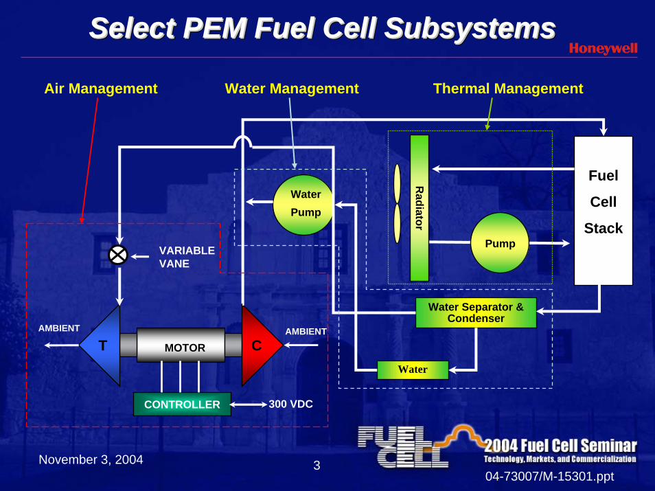
Select PEM Fuel Cell SubsystemsSelect PEM Fuel Cell SubsystemsSelect PEM Fuel Cell Subsystems
Fuel
Cell
Stack
Water Separator & Condenser
PumpR
adiator
Thermal Management
Water Pump
Water
MOTORT CAMBIENTAMBIENT
CONTROLLER 300 VDC
VARIABLEVANE
Water ManagementAir Management
November 3, 200404-73007/M-15301.ppt
4
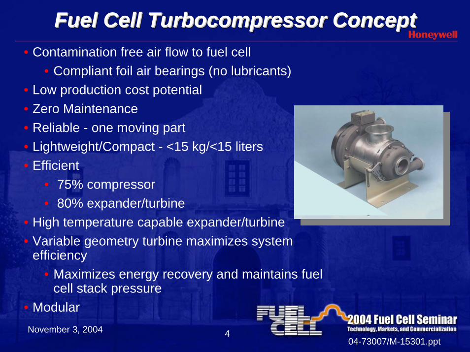
Fuel Cell Turbocompressor ConceptFuel Cell Turbocompressor ConceptFuel Cell Turbocompressor Concept• Contamination free air flow to fuel cell
• Compliant foil air bearings (no lubricants) • Low production cost potential • Zero Maintenance• Reliable - one moving part• Lightweight/Compact - <15 kg/<15 liters• Efficient
• 75% compressor• 80% expander/turbine
• High temperature capable expander/turbine• Variable geometry turbine maximizes system
efficiency• Maximizes energy recovery and maintains fuel
cell stack pressure• Modular
November 3, 200404-73007/M-15301.ppt
5
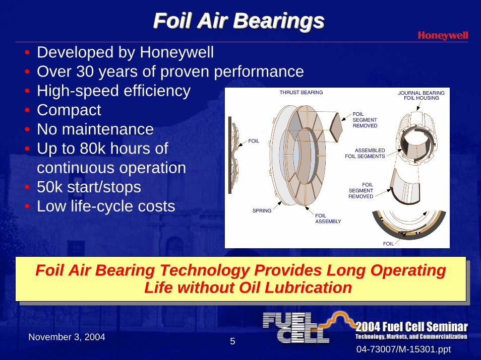
Foil Air BearingsFoil Air BearingsFoil Air Bearings• Developed by Honeywell• Over 30 years of proven performance• High-speed efficiency• Compact • No maintenance • Up to 80k hours of
continuous operation • 50k start/stops• Low life-cycle costs
Foil Air Bearing Technology Provides Long Operating Life without Oil Lubrication
Foil Air Bearing Technology Provides Long Operating Life without Oil Lubrication
November 3, 200404-73007/M-15301.ppt
6
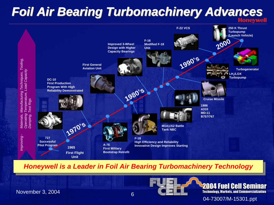
Foil Air Bearing Turbomachinery AdvancesFoil Air Bearing Turbomachinery AdvancesFoil Air Bearing Turbomachinery Advances250 K ThrustTurbopump(Launch Vehicle)
Impr
ovin
g-
Mat
eria
ls, M
anuf
actu
ring
Tech
niqu
es, T
oolin
g,O
pera
ting
Tem
pera
ture
, Loa
d C
apac
ityD
ampi
ng, T
est R
igs
DC-10First ProductionProgram With HighReliability Demonstrated
727Successful
Pilot Program
First GeneralAviation Unit
Improved 3-WheelDesign with HigherCapacity Bearings
A-7EFirst MilitaryBootstrap Retrofit
F-18High Efficiency and Reliability Innovative Design Improves Starting
M1A1/A2 Battle Tank NBC
F-16Modified F-18Unit
F-22 VCS
Turbogenerator
Cruise Missile
LH2/LOXTurbopump
1986A310MD-11B757/767
1970’s
First FlightUnit
1965
Honeywell is a Leader in Foil Air Bearing Turbomachinery TechnologyHoneywell is a Leader in Foil Air Bearing Turbomachinery Technology
1980’s
1990’s
2000
November 3, 200404-73007/M-15301.ppt
7
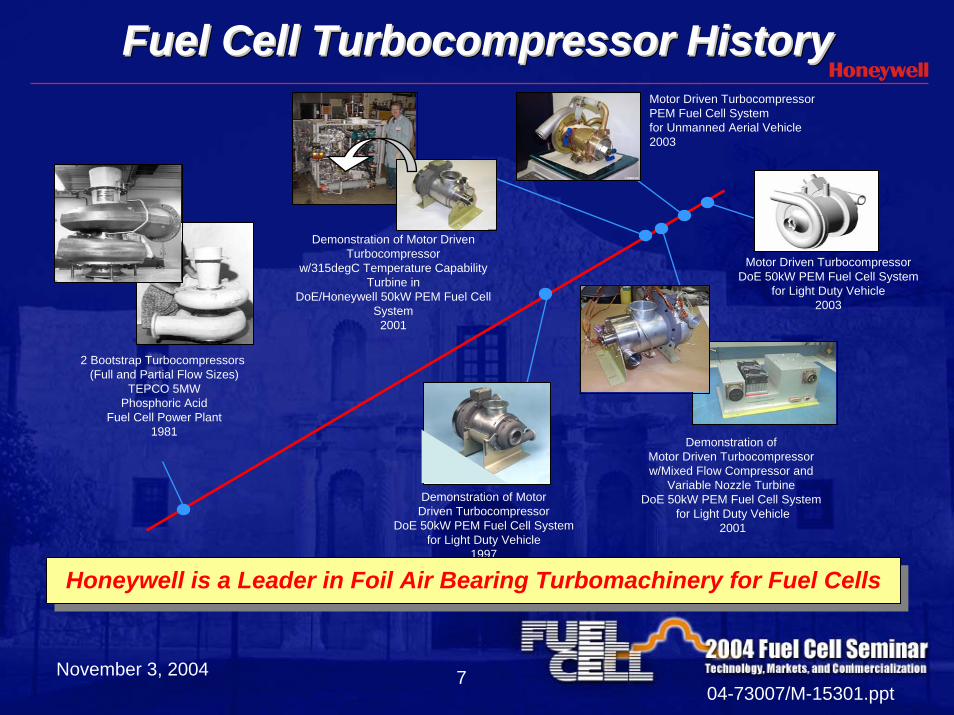
Fuel Cell Turbocompressor HistoryFuel Cell Turbocompressor HistoryFuel Cell Turbocompressor History
2 Bootstrap Turbocompressors (Full and Partial Flow Sizes)
TEPCO 5MWPhosphoric Acid
Fuel Cell Power Plant1981
Demonstration of Motor Driven Turbocompressor w/Mixed Flow Compressor and
Variable Nozzle Turbine DoE 50kW PEM Fuel Cell System
for Light Duty Vehicle2001
Demonstration of Motor Driven Turbocompressor
w/315degC Temperature Capability Turbine in
DoE/Honeywell 50kW PEM Fuel Cell System
2001
Motor Driven Turbocompressor DoE 50kW PEM Fuel Cell System
for Light Duty Vehicle2003
Demonstration of MotorDriven Turbocompressor
DoE 50kW PEM Fuel Cell Systemfor Light Duty Vehicle
1997
Motor Driven Turbocompressor PEM Fuel Cell System for Unmanned Aerial Vehicle2003
Honeywell is a Leader in Foil Air Bearing Turbomachinery for Fuel CellsHoneywell is a Leader in Foil Air Bearing Turbomachinery for Fuel Cells
November 3, 200404-73007/M-15301.ppt
8
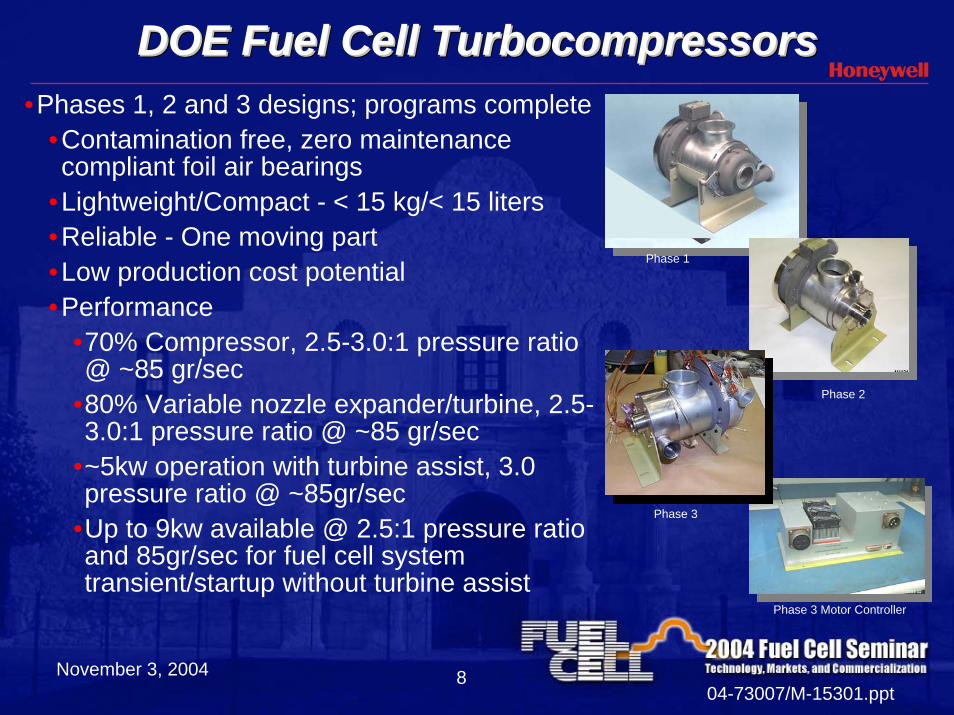
DOE Fuel Cell TurbocompressorsDOE Fuel Cell TurbocompressorsDOE Fuel Cell Turbocompressors•Phases 1, 2 and 3 designs; programs complete
•Contamination free, zero maintenance compliant foil air bearings
•Lightweight/Compact - < 15 kg/< 15 liters•Reliable - One moving part•Low production cost potential•Performance
•70% Compressor, 2.5-3.0:1 pressure ratio @ ~85 gr/sec
•80% Variable nozzle expander/turbine, 2.5-3.0:1 pressure ratio @ ~85 gr/sec
•~5kw operation with turbine assist, 3.0 pressure ratio @ ~85gr/sec
•Up to 9kw available @ 2.5:1 pressure ratio and 85gr/sec for fuel cell system transient/startup without turbine assist
Phase 1
Phase 2
Phase 3
Phase 3 Motor Controller
November 3, 200404-73007/M-15301.ppt
9
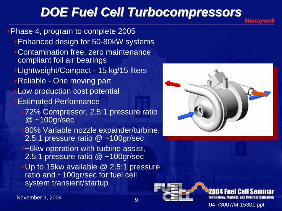
DOE Fuel Cell TurbocompressorsDOE Fuel Cell TurbocompressorsDOE Fuel Cell Turbocompressors•Phase 4, program to complete 2005
•Enhanced design for 50-80kW systems•Contamination free, zero maintenance compliant foil air bearings
•Lightweight/Compact - 15 kg/15 liters •Reliable - One moving part•Low production cost potential•Estimated Performance
•72% Compressor, 2.5:1 pressure ratio @ ~100gr/sec
•80% Variable nozzle expander/turbine, 2.5:1 pressure ratio @ ~100gr/sec
•~6kw operation with turbine assist, 2.5:1 pressure ratio @ ~100gr/sec
•Up to 15kw available @ 2.5:1 pressure ratio and ~100gr/sec for fuel cell system transient/startup
November 3, 200404-73007/M-15301.ppt
10
Future Turbocompressor DirectionFuture Turbocompressor Direction• By year 2010
• Improve performance•80% efficient compressor•85% efficient turbine
• Continue to investigate manufacturing costs •$400/unit @ 100,000 units/year
November 3, 200404-73007/M-15301.ppt
11
Development of a Thermal and Water Management
(TWM) System for PEM Fuel Cells
November 3, 200404-73007/M-15301.ppt
12
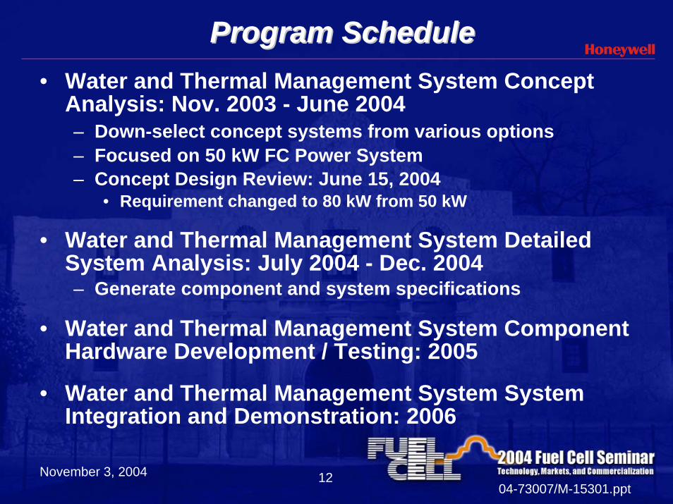
Program ScheduleProgram Schedule• Water and Thermal Management System Concept
Analysis: Nov. 2003 - June 2004– Down-select concept systems from various options– Focused on 50 kW FC Power System– Concept Design Review: June 15, 2004
• Requirement changed to 80 kW from 50 kW
• Water and Thermal Management System Detailed System Analysis: July 2004 - Dec. 2004– Generate component and system specifications
• Water and Thermal Management System Component Hardware Development / Testing: 2005
• Water and Thermal Management System System Integration and Demonstration: 2006
November 3, 200404-73007/M-15301.ppt
13
Concept System AnalysisConcept System Analysis
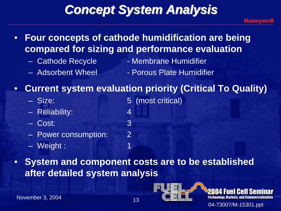
• Four concepts of cathode humidification are being compared for sizing and performance evaluation– Cathode Recycle - Membrane Humidifier– Adsorbent Wheel - Porous Plate Humidifier
• Current system evaluation priority (Critical To Quality)– Size: 5 (most critical)– Reliability: 4– Cost: 3– Power consumption: 2– Weight : 1
• System and component costs are to be established after detailed system analysis
November 3, 200404-73007/M-15301.ppt
14
Cathode Humidification AlternativesCathode Humidification Alternatives
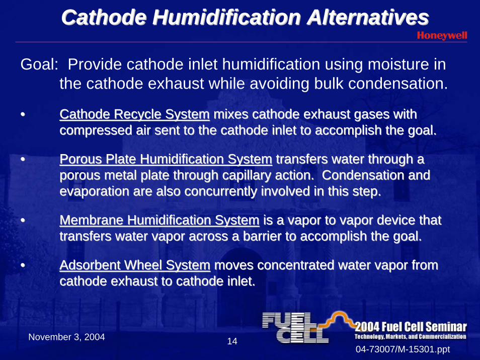
Goal: Provide cathode inlet humidification using moisture in the cathode exhaust while avoiding bulk condensation.
•• Cathode Recycle SystemCathode Recycle System mixes cathode exhaust gases with mixes cathode exhaust gases with compressed air sent to the cathode inlet to accomplish the goal.compressed air sent to the cathode inlet to accomplish the goal.
•• Porous Plate Humidification SystemPorous Plate Humidification System transfers water through a transfers water through a porous metal plate through capillary action. Condensation and porous metal plate through capillary action. Condensation and evaporation are also concurrently involved in this step.evaporation are also concurrently involved in this step.
•• Membrane Humidification SystemMembrane Humidification System is a vapor to vapor device that is a vapor to vapor device that transfers water vapor across a barrier to accomplish the goal.transfers water vapor across a barrier to accomplish the goal.
•• Adsorbent Wheel SystemAdsorbent Wheel System moves concentrated water vapor from moves concentrated water vapor from cathode exhaust to cathode inlet. cathode exhaust to cathode inlet.
November 3, 200404-73007/M-15301.ppt
15
Cathode Recycle System AnalysisCathode Recycle System Analysis
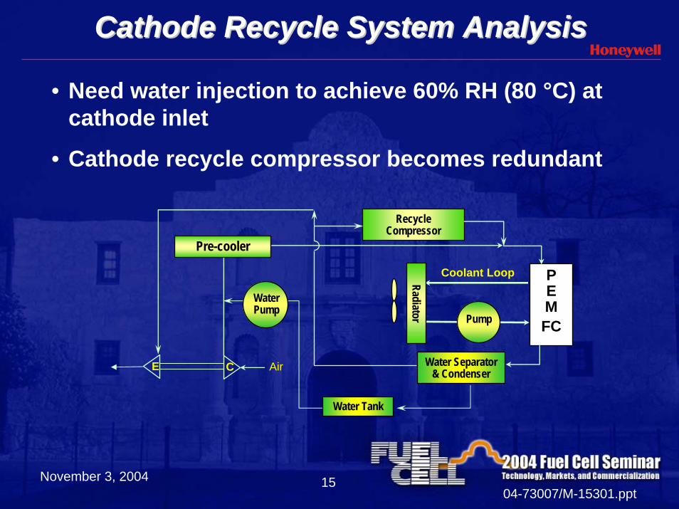
• Need water injection to achieve 60% RH (80 °C) at cathode inlet
• Cathode recycle compressor becomes redundant
PEMFC
AirCE
Recycle Compressor
Water Separator & Condenser
Pump
RadiatorCoolant Loop
Water Pump
Pre-cooler
Water Tank
November 3, 200404-73007/M-15301.ppt
16
Water Injection System SchematicWater Injection System Schematic
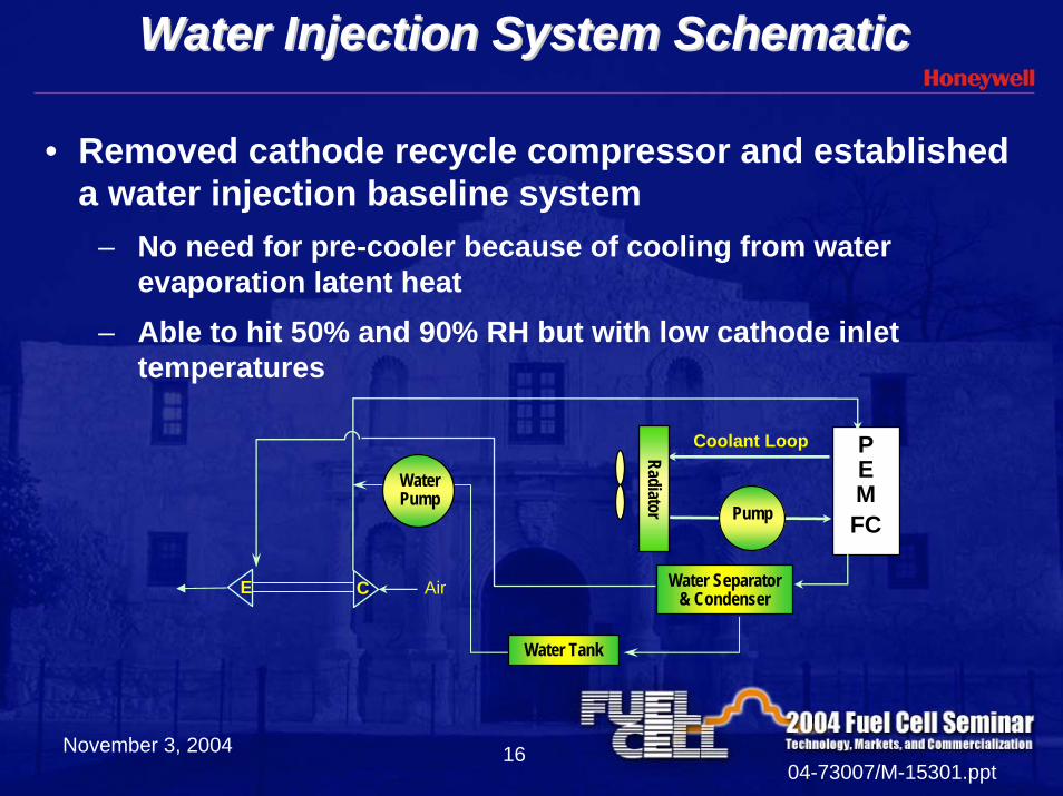
• Removed cathode recycle compressor and established a water injection baseline system
– No need for pre-cooler because of cooling from water evaporation latent heat
– Able to hit 50% and 90% RH but with low cathode inlet temperatures
PEMFC
AirCE Water Separator & Condenser
Pump
Radiator
Coolant Loop
Water Pump
Water Tank
November 3, 200404-73007/M-15301.ppt
17
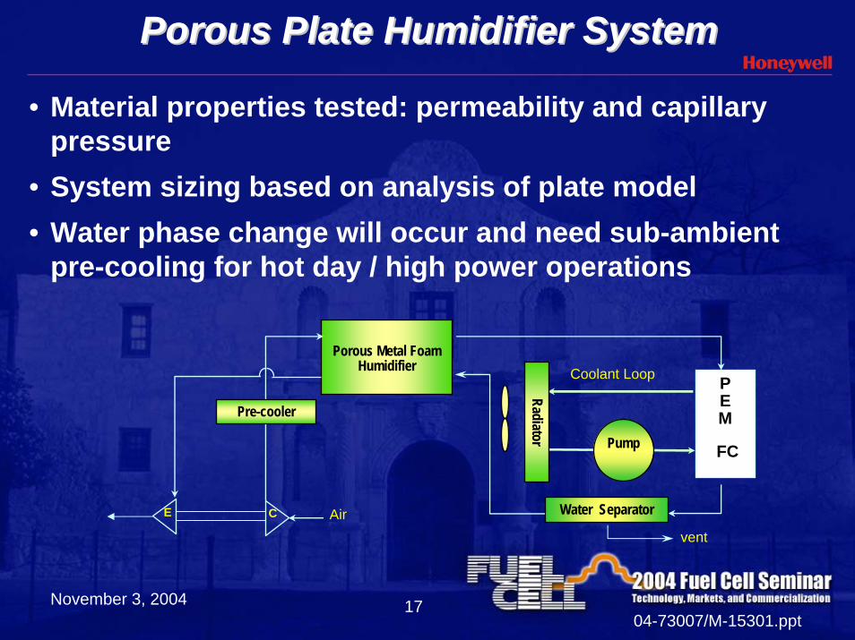
Porous Plate Humidifier SystemPorous Plate Humidifier System
• Material properties tested: permeability and capillary pressure
• System sizing based on analysis of plate model• Water phase change will occur and need sub-ambient
pre-cooling for hot day / high power operations
AirCE
Porous Metal Foam Humidifier
vent
Water Separator
Pump
Radiator
Coolant Loop
Pre-cooler
PEM
FC
November 3, 200404-73007/M-15301.ppt
18
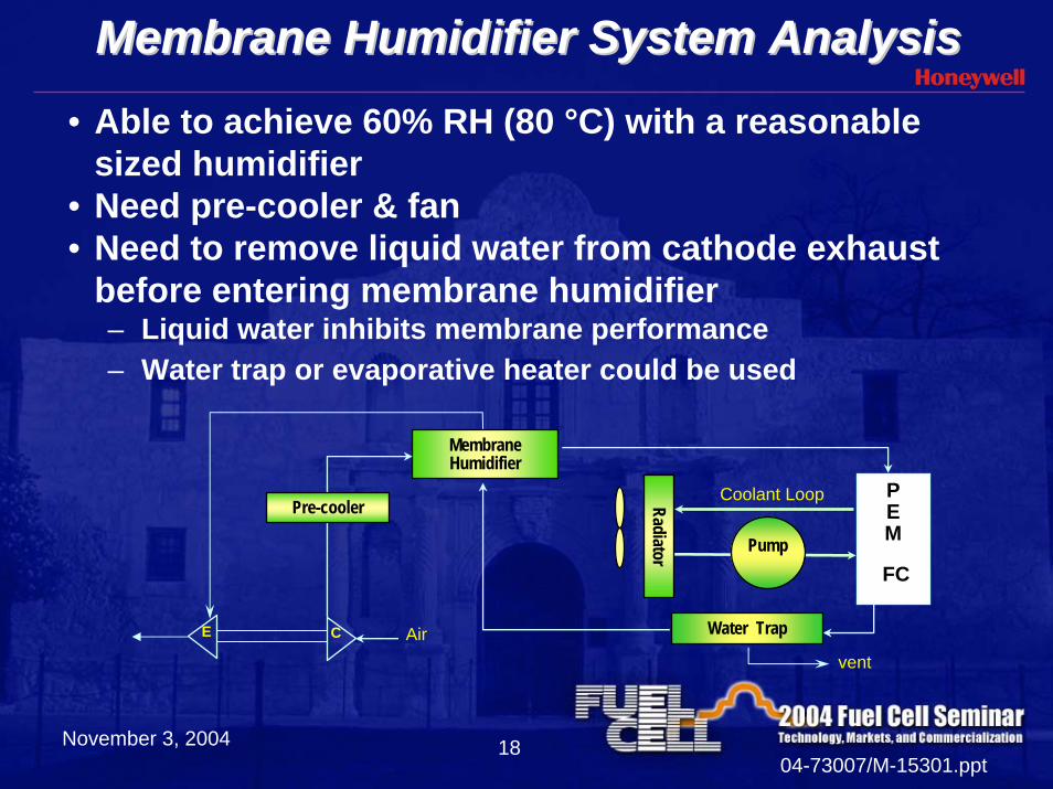
Membrane Humidifier System AnalysisMembrane Humidifier System Analysis• Able to achieve 60% RH (80 °C) with a reasonable
sized humidifier • Need pre-cooler & fan• Need to remove liquid water from cathode exhaust
before entering membrane humidifier– Liquid water inhibits membrane performance– Water trap or evaporative heater could be used
Membrane Humidifier
AirCE
vent
Water Trap
Pump
Radiator
Coolant LoopPre-cooler
PEM
FC
November 3, 200404-73007/M-15301.ppt
19
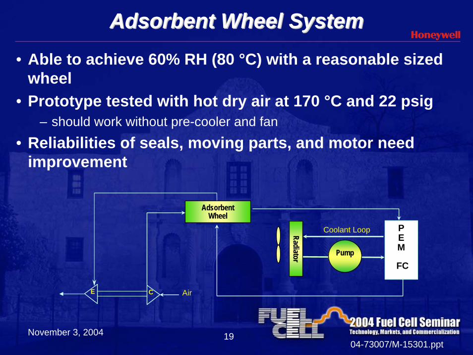
Adsorbent Wheel SystemAdsorbent Wheel System• Able to achieve 60% RH (80 °C) with a reasonable sized
wheel• Prototype tested with hot dry air at 170 °C and 22 psig
– should work without pre-cooler and fan
• Reliabilities of seals, moving parts, and motor need improvement
Adsorbent Wheel
AirCE
Pump
Radiator
Coolant Loop PEM
FC
November 3, 200404-73007/M-15301.ppt
20
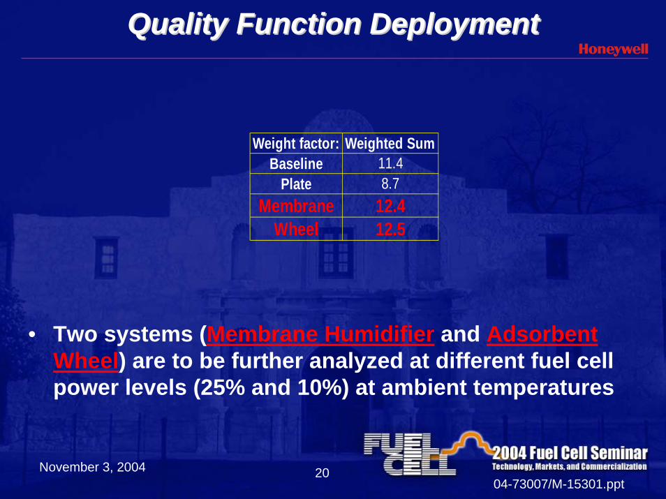
Quality Function DeploymentQuality Function Deployment
Weight factor: Weighted SumBaseline 11.4
Plate 8.7Membrane 12.4
Wheel 12.5
• Two systems (Membrane Humidifier and Adsorbent Wheel) are to be further analyzed at different fuel cell power levels (25% and 10%) at ambient temperatures
November 3, 200404-73007/M-15301.ppt
21
Radiator Trade StudyRadiator Trade Study
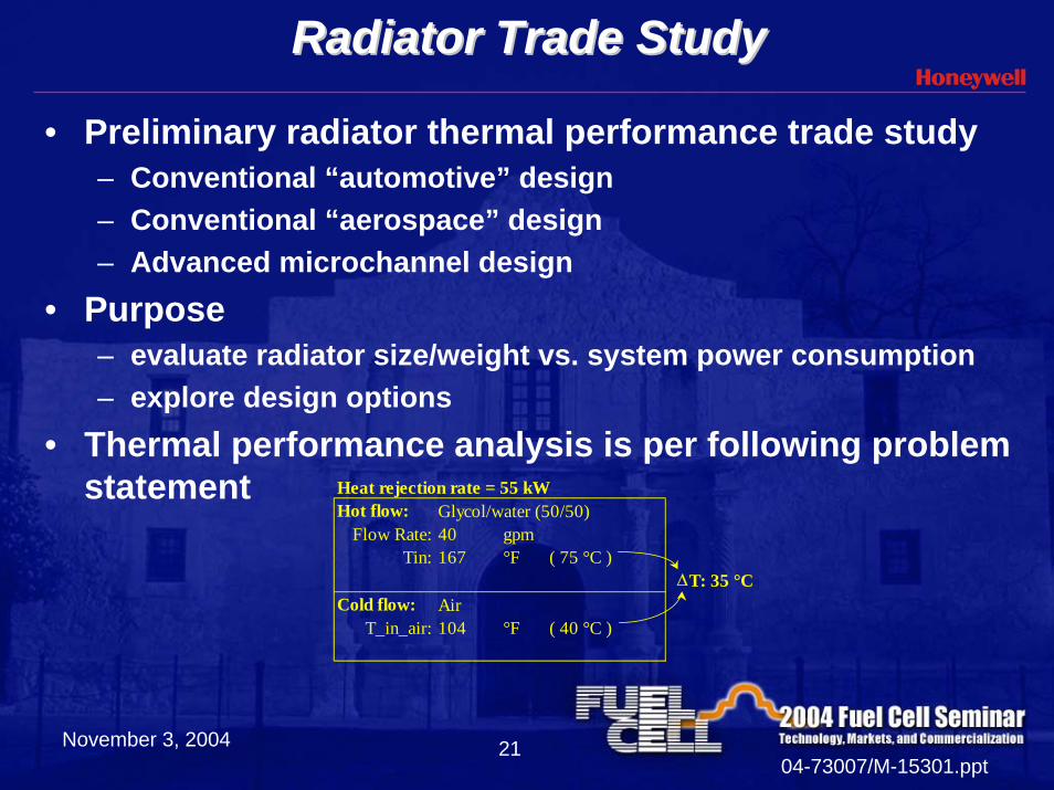
• Preliminary radiator thermal performance trade study– Conventional “automotive” design– Conventional “aerospace” design– Advanced microchannel design
• Purpose– evaluate radiator size/weight vs. system power consumption– explore design options
• Thermal performance analysis is per following problem statement Heat rejection rate = 55 kW
Hot flow: Glycol/water (50/50)Flow Rate: 40 gpm
Tin: 167 °F ( 75 °C )∆T: 35 °C
Cold flow: AirT_in_air: 104 °F ( 40 °C )
November 3, 200404-73007/M-15301.ppt
22
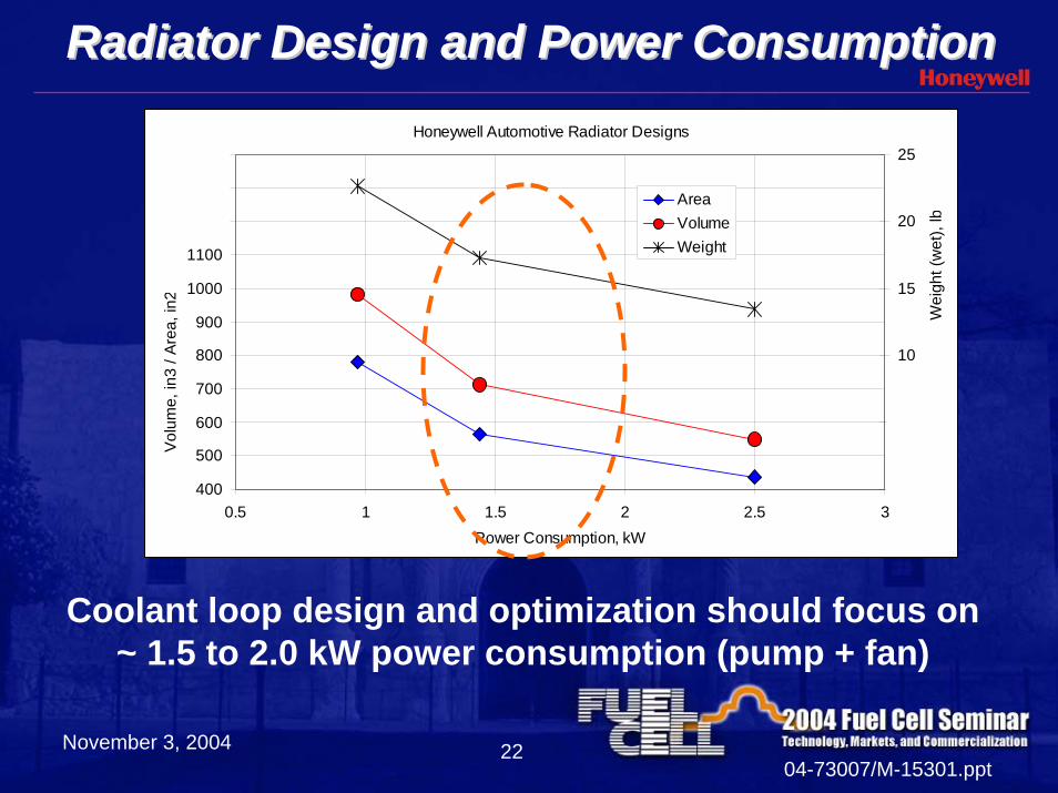
Radiator Design and Power ConsumptionRadiator Design and Power ConsumptionHoneywell Automotive Radiator Designs
400
500
600
700
800
900
1000
1100
1200
1300
1400
0.5 1 1.5 2 2.5 3Power Consumption, kW
Vol
ume,
in3
/ Are
a, in
2
0
5
10
15
20
25
Wei
ght (
wet
), lb
AreaVolumeWeight
Coolant loop design and optimization should focus on ~ 1.5 to 2.0 kW power consumption (pump + fan)
November 3, 200404-73007/M-15301.ppt
23
Go Forward PlanGo Forward Plan• For an 80 kW FC system, conduct component design
– Adsorbent Wheel and Membrane Humidifier systems– Steady state loads at 100%, 25%, and 10% of 80 kW– Ambient temperature: 40° C and 20 ° C– Hybrid radiator design: Honeywell automotive + aerospace R&D
• Start test stand design and setup– Establish demonstration test plan and define test requirement– Design test stand and instrumentation
• Development opportunities– Adsorbent Wheel: product development (motor, seals, etc.)– Membrane Humidifier: lower cost / higher temperature resistance material
replacing Nafion

November 3, 200404-73007/M-15301.ppt
24
A Big Thank You!
U.S. Department of EnergyFuel Cell System Developers
For your encouragement and support
November 3, 200404-73007/M-15301.ppt
25
GUS ORDONEZPLATFORM LEADER - DEFENSE AND SPACE
Torrance, CAPhone: 310-512-2556
E-mail: [email protected]
MARK K. GEEFUEL CELL TURBOCOMPRESSORS
Torrance, CAPhone: 310-512-3606
E-mail: [email protected]
CHUNG LIUFUEL CELL THERMAL AND WATER MANAGEMENT
Torrance, CAPhone: 310-512-4328
E-mail: [email protected]