Embed Size (px)
Citation preview
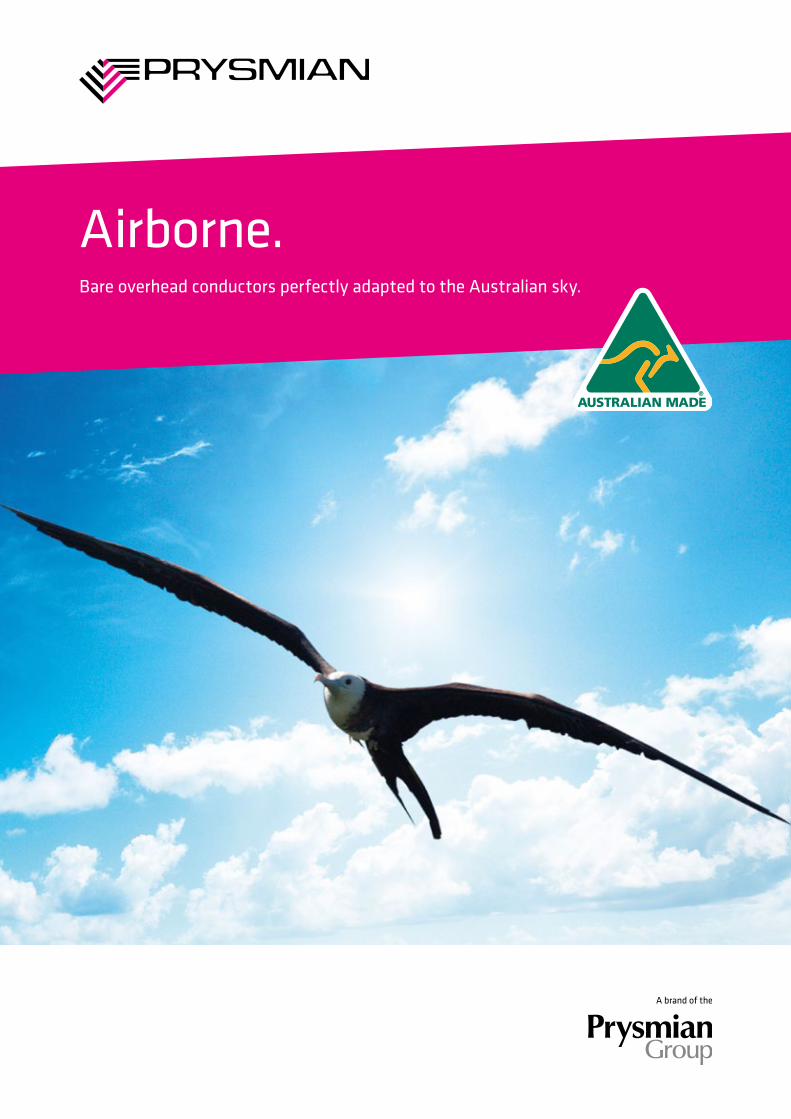
Airborne.Bare overhead conductors perfectly adapted to the Australian sky.
Introduction 3
Aluminium conductors AAC 1350 – All aluminium conductors 4
AAAC 1120 – All aluminium alloy conductors 5
Aluminium reinforced conductors
ACSR/GZ – Aluminium conductors, galvanised steel reinforced 6
ACSR/AC – Aluminium conductors, aluminium clad steel reinforced 7
AACSR/GZ – Aluminium alloy conductors, galvanised steel reinforced 8
AACSR/AC – Aluminium alloy conductors, aluminium clad steel reinforced 9
Copper conductors HDCU – Hard drawn copper conductors 10
General information Overhead conductor standards 11
Materials used in overhead conductors 11
Technical information Mechanical 13
Electrical 14
Contents
2 www.prysmiancable.com.au | www.prysmiancable.co.nz
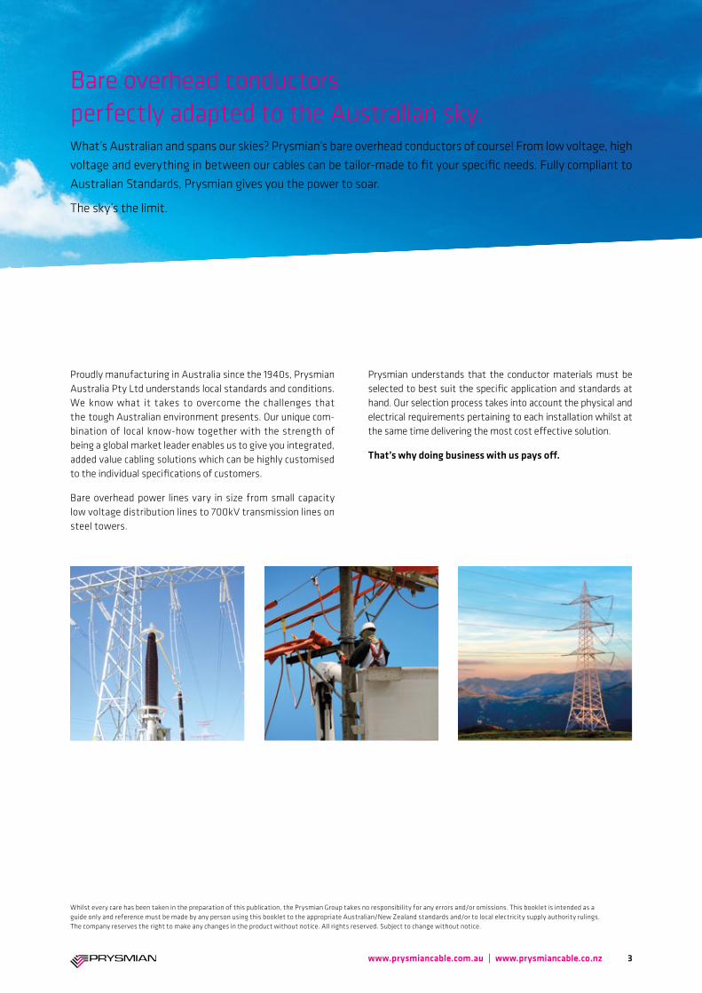
Bare overhead conductors perfectly adapted to the Australian sky.What’s Australian and spans our skies? Prysmian’s bare overhead conductors of course! From low voltage, high voltage and everything in between our cables can be tailor-made to fit your specific needs. Fully compliant to Australian Standards, Prysmian gives you the power to soar.
The sky’s the limit.
Proudly manufacturing in Australia since the 1940s, Prysmian Australia Pty Ltd understands local standards and conditions. We know what it takes to overcome the challenges that the tough Australian environment presents. Our unique com-bination of local know-how together with the strength of being a global market leader enables us to give you integrated, added value cabling solutions which can be highly customised to the individual specifications of customers.
Bare overhead power lines vary in size from small capacity low voltage distribution lines to 700kV transmission lines on steel towers.
Prysmian understands that the conductor materials must be selected to best suit the specific application and standards at hand. Our selection process takes into account the physical and electrical requirements pertaining to each installation whilst at the same time delivering the most cost effective solution.
That’s why doing business with us pays off.
Whilst every care has been taken in the preparation of this publication, the Prysmian Group takes no responsibility for any errors and/or omissions. This booklet is intended as a guide only and reference must be made by any person using this booklet to the appropriate Australian/New Zealand standards and/or to local electricity supply authority rulings. The company reserves the right to make any changes in the product without notice. All rights reserved. Subject to change without notice.
3www.prysmiancable.com.au | www.prysmiancable.co.nz
Product code
Strand/wire diameter No/mm
Nominal C.S.A. mm2
Nominal O.D. mm
Approximate Mass
kg/km
Calculated minimum
breaking load kN
Final modulus of elasticity
GPa
Coefficient of linear expansion
/°C x 10-6
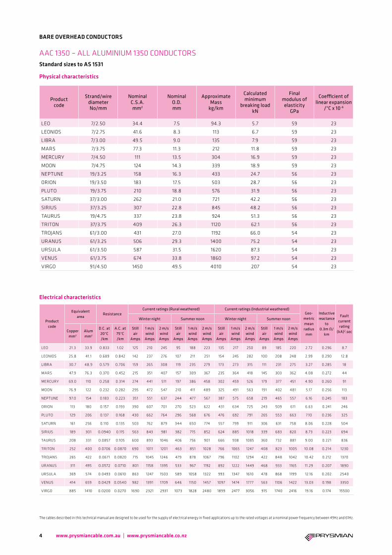
LEO 7/2.50 34.4 7.5 94.3 5.7 59 23
LEONIDS 7/2.75 41.6 8.3 113 6.7 59 23
LIBRA 7/3.00 49.5 9.0 135 7.9 59 23
MARS 7/3.75 77.3 11.3 212 11.8 59 23
MERCURY 7/4.50 111 13.5 304 16.9 59 23
MOON 7/4.75 124 14.3 339 18.9 59 23
NEPTUNE 19/3.25 158 16.3 433 24.7 56 23
ORION 19/3.50 183 17.5 503 28.7 56 23
PLUTO 19/3.75 210 18.8 576 31.9 56 23
SATURN 37/3.00 262 21.0 721 42.2 56 23
SIRIUS 37/3.25 307 22.8 845 48.2 56 23
TAURUS 19/4.75 337 23.8 924 51.3 56 23
TRITON 37/3.75 409 26.3 1120 62.1 56 23
TROJANS 61/3.00 431 27.0 1192 66.0 54 23
URANUS 61/3.25 506 29.3 1400 75.2 54 23
URSULA 61/3.50 587 31.5 1620 87.3 54 23
VENUS 61/3.75 674 33.8 1860 97.2 54 23
VIRGO 91/4.50 1450 49.5 4010 207 54 23
Product code
Equivalent area
ResistanceCurrent ratings (Rural weathered) Current ratings (Industrial weathered)
Geo-metric mean radius
mm
Inductive reactance
to 0.3m Ω/
km
Fault current rating
(kA)2.sec
Winter night Summer noon Winter night Summer noon
Copper mm2
Alum mm2
D.C. at 20°C /km
A.C. at 75°C /km
Still air
Amps
1 m/s wind Amps
2 m/s wind Amps
Still air
Amps
1 m/s wind Amps
2 m/s wind Amps
Still air
Amps
1 m/s wind Amps
2 m/s wind Amps
Still air
Amps
1 m/s wind Amps
2 m/s wind Amps
LEO 21.3 33.9 0.833 1.02 125 210 245 95 188 223 135 217 250 89 185 220 2.72 0.296 8.7
LEONIDS 25.8 41.1 0.689 0.842 142 237 276 107 211 251 154 245 282 100 208 248 2.99 0.290 12.8
LIBRA 30.7 48.9 0.579 0.706 159 265 308 119 235 279 173 273 315 111 231 275 3.27 0.285 18
MARS 47.9 76.3 0.370 0.452 215 351 407 157 309 367 235 364 418 145 303 362 4.08 0.272 44
MERCURY 69.0 110 0.258 0.314 274 441 511 197 386 458 302 459 526 179 377 451 4.90 0.260 91
MOON 76.9 122 0.232 0.282 295 472 547 210 411 489 325 491 563 191 402 481 5.17 0.256 113
NEPTUNE 97.0 154 0.183 0.223 351 551 637 244 477 567 387 575 658 219 465 557 6.16 0.245 183
ORION 113 180 0.157 0.193 390 607 701 270 523 622 431 634 725 243 509 611 6.63 0.241 246
PLUTO 129 206 0.137 0.168 430 662 764 296 568 676 476 692 791 265 553 663 7.10 0.236 325
SATURN 161 256 0.110 0.135 503 762 879 344 650 774 557 799 911 306 631 758 8.06 0.228 504
SIRIUS 189 301 0.0940 0.115 563 843 981 382 715 852 624 885 1018 339 683 820 8.73 0.223 694
TAURUS 208 331 0.0857 0.105 600 893 1046 406 756 901 666 938 1085 360 732 881 9.00 0.221 836
TRITON 252 400 0.0706 0.0870 690 1011 1201 463 851 1028 766 1065 1247 408 823 1005 10.08 0.214 1230
TROJANS 265 422 0.0671 0.0820 715 1045 1246 479 878 1067 796 1102 1294 422 848 1042 10.42 0.212 1370
URANUS 311 495 0.0572 0.0710 801 1158 1395 533 967 1192 892 1222 1449 468 933 1165 11.29 0.207 1890
URSULA 369 574 0.0493 0.0610 863 1247 1503 589 1058 1322 993 1347 1610 478 868 1199 12.16 0.202 2540
VENUS 414 659 0.0429 0.0540 982 1391 1709 646 1150 1457 1097 1474 1777 563 1106 1422 13.03 0.198 3350
VIRGO 885 1410 0.0200 0.0270 1690 2321 2931 1073 1828 2480 1899 2477 3056 915 1740 2416 19.16 0.174 15500
AAC 1350 – ALL ALUMINIUM 1350 CONDUCTORS Standard sizes to AS 1531
4
BARE OVERHEAD CONDUCTORS
Physical characteristics
www.prysmiancable.com.au | www.prysmiancable.co.nz
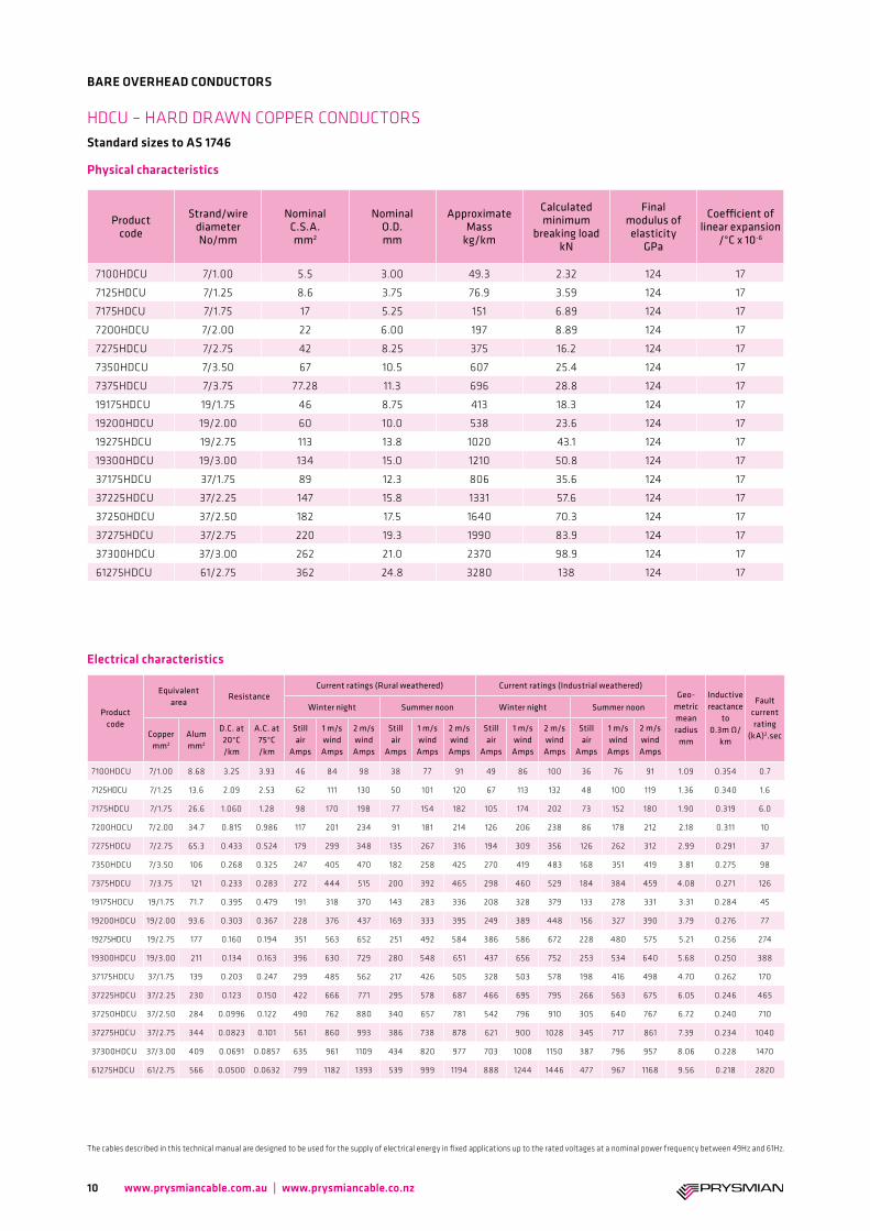
The cables described in this technical manual are designed to be used for the supply of electrical energy in fixed applications up to the rated voltages at a nominal power frequency between 49Hz and 61Hz.
Electrical characteristics
Product code
Strand/wire diameter No/mm
Nominal C.S.A. mm2
Nominal O.D. mm
Approximate Mass
kg/km
Calculated minimum
breaking load kN
Final modulus of elasticity
GPa
Coefficient of linear expansion
/°C x 10-6
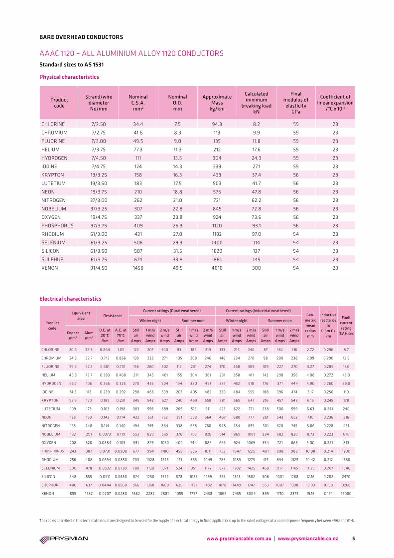
CHLORINE 7/2.50 34.4 7.5 94.3 8.2 59 23
CHROMIUM 7/2.75 41.6 8.3 113 9.9 59 23
FLUORINE 7/3.00 49.5 9.0 135 11.8 59 23
HELIUM 7/3.75 77.3 11.3 212 17.6 59 23
HYDROGEN 7/4.50 111 13.5 304 24.3 59 23
IODINE 7/4.75 124 14.3 339 27.1 59 23
KRYPTON 19/3.25 158 16.3 433 37.4 56 23
LUTETIUM 19/3.50 183 17.5 503 41.7 56 23
NEON 19/3.75 210 18.8 576 47.8 56 23
NITROGEN 37/3.00 262 21.0 721 62.2 56 23
NOBELIUM 37/3.25 307 22.8 845 72.8 56 23
OXYGEN 19/4.75 337 23.8 924 73.6 56 23
PHOSPHORUS 37/3.75 409 26.3 1120 93.1 56 23
RHODIUM 61/3.00 431 27.0 1192 97.0 54 23
SELENIUM 61/3.25 506 29.3 1400 114 54 23
SILICON 61/3.50 587 31.5 1620 127 54 23
SULPHUR 61/3.75 674 33.8 1860 145 54 23
XENON 91/4.50 1450 49.5 4010 300 54 23
Product code
Equivalent area
ResistanceCurrent ratings (Rural weathered) Current ratings (Industrial weathered)
Geo-metric mean radius
mm
Inductive reactance
to 0.3m Ω/
km
Fault current rating
(kA)2.sec
Winter night Summer noon Winter night Summer noon
Copper mm2
Alum mm2
D.C. at 20°C /km
A.C. at 75°C /km
Still air
Amps
1 m/s wind Amps
2 m/s wind Amps
Still air
Amps
1 m/s wind Amps
2 m/s wind Amps
Still air
Amps
1 m/s wind Amps
2 m/s wind Amps
Still air
Amps
1 m/s wind Amps
2 m/s wind Amps
CHLORINE 20.6 32.8 0.864 1.05 122 207 240 93 185 219 133 213 246 87 182 216 2.72 0.296 8.7
CHROMIUM 24.9 39.7 0.713 0.866 139 233 271 105 208 246 146 234 270 98 200 238 2.99 0.290 12.6
FLUORINE 29.6 47.2 0.601 0.731 156 260 302 117 231 274 170 268 309 109 227 270 3.27 0.285 17.6
HELIUM 46.3 73.7 0.383 0.468 211 345 401 155 304 361 231 358 411 142 298 356 4.08 0.272 43.0
HYDROGEN 66.7 106 0.266 0.325 270 435 504 194 380 451 297 452 518 176 371 444 4.90 0.260 89.0
IODINE 74.3 118 0.239 0.292 290 466 539 207 405 482 320 484 555 188 396 474 5.17 0.256 110
KRYPTON 93.9 150 0.189 0.231 345 542 627 240 469 558 381 565 647 216 457 548 6.16 0.245 178
LUTETIUM 109 173 0.163 0.198 383 596 689 265 513 611 423 622 711 238 500 599 6.63 0.241 240
NEON 125 199 0.142 0.174 422 651 752 291 558 664 467 680 777 261 543 652 7.10 0.236 316
NITROGEN 155 248 0.114 0.140 494 749 864 338 638 760 548 784 895 301 620 745 8.06 0.228 491
NOBELIUM 182 291 0.0973 0.119 553 829 965 376 703 828 614 869 1001 334 682 820 8.73 0.223 676
OXYGEN 208 320 0.0884 0.109 591 879 1030 400 744 887 656 924 1069 354 721 868 9.00 0.221 813
PHOSPHORUS 243 387 0.0731 0.0900 677 994 1180 455 836 1011 753 1047 1225 401 808 988 10.08 0.214 1200
RHODIUM 256 408 0.0694 0.0850 703 1028 1226 471 863 1049 783 1083 1273 415 834 1025 10.42 0.212 1330
SELENIUM 300 478 0.0592 0.0730 788 1138 1371 524 951 1172 877 1202 1425 460 917 1145 11.29 0.207 1840
SILICON 348 555 0.0511 0.0630 874 1250 1522 578 1039 1299 975 1323 1582 506 1001 1268 12.16 0.202 2470
SULPHUR 400 637 0.0444 0.0560 966 1368 1680 635 1131 1432 1078 1449 1747 553 1087 1398 13.03 0.198 3260
XENON 855 1632 0.0207 0.0280 1662 2282 2881 1055 1797 2438 1866 2435 3004 899 1710 2375 19.16 0.174 15000
AAAC 1120 – ALL ALUMINIUM ALLOY 1120 CONDUCTORS Standard sizes to AS 1531
5
BARE OVERHEAD CONDUCTORS
Physical characteristics
www.prysmiancable.com.au | www.prysmiancable.co.nz
The cables described in this technical manual are designed to be used for the supply of electrical energy in fixed applications up to the rated voltages at a nominal power frequency between 49Hz and 61Hz.
Electrical characteristics
Product code
Equivalent area
ResistanceCurrent ratings (Rural weathered) Current ratings (Industrial weathered)
Geo-metric mean radius
mm
Inductive reactance
to 0.3m Ω/
km
Fault current rating
(kA)2.sec
Winter night Summer noon Winter night Summer noon
Copper mm2
Alum mm2
D.C. at 20°C /km
A.C. at 75°C /km
Still air
Amps
1 m/s wind Amps
2 m/s wind Amps
Still air
Amps
1 m/s wind Amps
2 m/s wind Amps
Still air
Amps
1 m/s wind Amps
2 m/s wind Amps
Still air
Amps
1 m/s wind Amps
2 m/s wind Amps
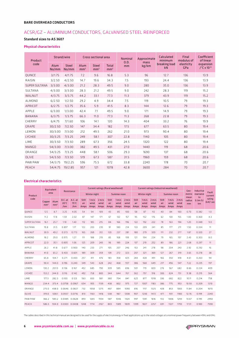
QUINCE 5.5 8.7 3.25 4.05 54 94 109 43 85 100 58 87 112 40 84 100 0.70 0.382 1.0
RAISIN 11.2 17.8 1.59 2.02 87 147 171 67 132 157 95 152 176 62 130 155 1.00 0.360 4.3
SUPER SULTANA 16.1 25.7 1.10 1.43 112 185 215 84 166 196 122 192 222 78 163 194 1.20 0.348 9.0
SULTANA 19.8 31.5 0.897 1.17 122 203 235 91 180 214 133 209 241 85 177 211 1.50 0.334 11
WALNUT 30.9 49.2 0.573 0.773 165 269 312 120 237 281 180 279 320 111 232 277 1.87 0.320 27
ALMOND 18.2 29.0 0.975 1.27 111 188 219 85 168 199 121 194 224 79 165 197 2.43 0.303 8.0
APRICOT 22.0 35.1 0.805 1.06 125 209 243 96 189 224 137 219 252 89 186 221 2.68 0.297 11
APPLE 26.2 41.8 0.677 0.900 140 233 271 105 207 246 153 241 278 98 204 243 2.92 0.292 16
BANANA 41.0 65.2 0.433 0.601 189 309 359 139 272 323 207 321 369 127 267 319 3.65 0.278 38
CHERRY 65.8 104.7 0.271 0.403 257 411 476 183 358 425 283 428 491 166 350 418 4.61 0.263 94
GRAPE 90.4 144.0 0.196 0.240 349 543 628 242 468 557 386 568 649 217 456 547 7.22 0.235 197
LEMON 130.2 207.0 0.136 0.167 452 685 790 309 585 696 501 719 820 276 567 682 8.66 0.224 409
LYCHEE 153.2 244.0 0.116 0.142 492 758 883 344 644 767 562 797 916 306 624 751 9.38 0.219 564
LIME 177.3 282.3 0.100 0.123 563 833 981 380 704 841 625 877 1018 336 682 822 10.11 0.214 758
MANGO 234.4 373.4 0.0758 0.0967 654 955 1139 438 802 975 727 1007 1183 386 775 953 10.93 0.209 1210
ORANGE 275.0 438.0 0.0646 0.0827 732 1058 1275 487 884 1090 816 1117 1325 428 853 1065 11.84 0.204 1670
OLIVE 319.0 508.1 0.0557 0.0716 813 1163 1416 538 967 1208 907 1230 1472 471 931 1180 12.76 0.199 2240
PAW PAW 366.2 583.2 0.0485 0.0628 893 1265 1554 587 1046 1324 997 1341 1616 512 1006 1293 13.67 0.195 2950
PEACH 586.5 934.0 0.0303 0.0408 1248 1714 2167 803 1389 1839 1399 1827 2257 691 1327 1793 17.31 0.180 7590
Product code
Strand/wire Cross sectional area Nominal O.D. mm
Approximate mass
kg/km
Calculated minimum
breaking load kN
Final modulus of elasticity
GPa
Coefficient of linear
expansion /°C x 10-6Alum
No/mmSteel
No/mmAlum mm2
Steel mm2
Total mm2
QUINCE 3/1.75 4/1.75 7.2 9.6 16.8 5.3 96 12.7 136 13.9
RAISIN 3/2.50 4/2.50 14.7 19.6 34.3 7.5 193 24.4 136 13.9
SUPER SULTANA 3/3.00 4/3.00 21.2 28.3 49.5 9.0 280 35.0 136 13.9
SULTANA 4/3.00 3/3.00 28.3 21.2 49.5 9.0 242 28.3 119 15.2
WALNUT 4/3.75 3/3.75 44.2 33.1 77.3 11.3 379 43.9 119 15.2
ALMOND 6/2.50 1/2.50 29.2 4.9 34.4 7.5 119 10.5 79 19.3
APRICOT 6/2.75 1/2.75 35.6 5.9 41.5 8.3 144 12.6 79 19.3
APPLE 6/3.00 1/3.00 42.4 7.1 49.5 9.0 171 14.9 79 19.3
BANANA 6/3.75 1/3.75 66.3 11.0 77.3 11.3 268 22.8 79 19.3
CHERRY 6/4.75 7/1.60 106 14.1 120 14.3 404 33.2 76 19.9
GRAPE 30/2.50 7/2.50 147 34.4 182 17.5 677 63.5 80 19.4
LEMON 30/3.00 7/3.00 212 49.5 262 21.0 973 90.4 80 19.4
LYCHEE 30/3.25 7/3.25 249 58.1 307 22.8 1140 105 80 19.4
LIME 30/3.50 7/3.50 289 67.3 356 24.5 1320 122 80 19.4
MANGO 54/3.00 7/3.00 382 49.5 431 27.0 1440 119 68 20.6
ORANGE 54/3.25 7/3.25 448 58.1 506 29.3 1690 137 68 20.6
OLIVE 54/3.50 7/3.50 519 67.3 587 31.5 1960 159 68 20.6
PAW PAW 54/3.75 19/2.25 596 75.5 672 33.8 2240 178 70 20.7
PEACH 54/4.75 19/2.85 957 121 1078 42.8 3600 284 70 20.7
ACSR/GZ – ALUMINIUM CONDUCTORS, GALVANISED STEEL REINFORCEDStandard sizes to AS 3607
Electrical characteristics
6
BARE OVERHEAD CONDUCTORS
Physical characteristics
www.prysmiancable.com.au | www.prysmiancable.co.nz
The cables described in this technical manual are designed to be used for the supply of electrical energy in fixed applications up to the rated voltages at a nominal power frequency between 49Hz and 61Hz.
Electrical characteristics
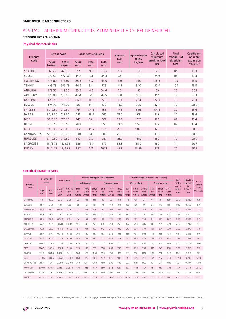
ACSR/AC – ALUMINIUM CONDUCTORS, ALUMINIUM CLAD STEEL REINFORCEDStandard sizes to AS 3607
Product code
Strand/wire Cross sectional area Nominal O.D. mm
Approximate mass
kg/km
Calculated minimum
breaking load kN
Final modulus of elasticity
GPa
Coefficient of linear
expansion /°C x 10-6Alum
No/mmSteel
No/mmAlum mm2
Steel mm2
Total mm2
SKATING 3/1.75 4/1.75 7.2 9.6 16.8 5.3 83 12.3 119 15.3
SOCCER 3/2.50 4/2.50 14.7 19.6 34.3 7.5 171 24.9 119 15.3
SWIMMING 4/3.00 3/3.00 28.3 21.2 49.5 9.0 218 28.9 106 16.5
TENNIS 4/3.75 3/3.75 44.2 33.1 77.3 11.3 340 42.6 106 16.5
ANGLING 6/2.50 1/2.50 29.5 4.9 34.4 7.5 113 10.6 79 20.1
ARCHERY 6/3.00 1/3.00 42.4 7.1 49.5 9.0 163 15.1 79 20.1
BASEBALL 6/3.75 1/3.75 66.3 11.0 77.3 11.3 254 22.3 79 20.1
BOWLS 6/4.75 7/1.60 106 14.1 120 14.3 385 32.7 76 20.6
CRICKET 30/2.50 7/2.50 147 34.4 182 17.5 636 64.4 82 19.4
DARTS 30/3.00 7/3.00 212 49.5 262 21.0 913 91.6 82 19.4
DICE 30/3.25 7/3.25 249 58.1 307 22.8 1070 106 82 19.4
DIVING 30/3.50 7/3.50 289 67.3 356 24.5 1240 122 82 19.4
GOLF 54/3.00 7/3.00 382 49.5 431 27.0 1380 120 75 20.6
GYMNASTICS 54/3.25 7/3.25 448 58.1 506 29.3 1620 139 75 20.6
HURDLES 54/3.50 7/3.50 519 67.3 587 31.5 1880 159 75 20.6
LACROSSE 54/3.75 19/2.25 596 75.5 672 33.8 2150 180 74 20.7
RUGBY 54/4.75 19/2.85 957 121 1078 42.8 3450 288 74 20.7
Product code
Equivalent area
ResistanceCurrent ratings (Rural weathered) Current ratings (Industrial weathered)
Geo-metric mean radius
mm
Inductive reactance
to 0.3m Ω/
km
Fault current rating
(kA)2.sec
Winter night Summer noon Winter night Summer noon
Copper mm2
Alum mm2
D.C. at 20°C /km
A.C. at 75°C /km
Still air
Amps
1 m/s wind Amps
2 m/s wind Amps
Still air
Amps
1 m/s wind Amps
2 m/s wind Amps
Still air
Amps
1 m/s wind Amps
2 m/s wind Amps
Still air
Amps
1 m/s wind Amps
2 m/s wind Amps
SKATING 6.5 10.3 2.75 3.35 59 102 119 46 93 110 63 105 122 44 91 109 0.70 0.382 1.4
SOCCER 13.3 21.1 1.34 1.63 95 161 187 73 144 171 103 166 191 68 142 169 1.00 0.360 5.7
SWIMMING 22.0 35.0 0.807 1.05 128 214 248 96 190 225 140 221 254 89 186 222 1.50 0.334 13
TENNIS 34.4 54.7 0.517 0.689 171 283 328 127 249 296 190 293 337 117 244 292 1.87 0.320 33
ANGLING 19.3 30.7 0.923 1.198 114 193 225 87 173 205 124 199 230 82 170 202 2.43 0.303 8.0
ARCHERY 27.7 44.1 0.641 0.844 144 240 279 108 213 253 157 248 285 100 209 249 2.92 0.292 16
BASEBALL 43.3 69.0 0.410 0.555 195 318 369 142 280 332 213 330 379 131 274 328 3.65 0.278 40
BOWLS 68.7 109.4 0.259 0.356 262 420 487 187 366 435 289 437 502 170 358 428 4.61 0.263 99
CRICKET 97.6 155.4 0.182 0.223 362 563 651 251 486 578 401 589 673 225 473 567 7.22 0.235 241
DARTS 140.5 223.8 0.126 0.155 470 712 821 321 607 723 521 746 850 286 590 708 8.66 0.224 444
DICE 164.9 262.6 0.108 0.133 525 786 916 356 667 786 582 825 950 317 647 778 9.38 0.219 611
DIVING 191.3 304.6 0.0928 0.114 584 865 1018 394 731 873 649 910 1057 349 708 852 10.11 0.214 821
GOLF 244.6 389.6 0.0726 0.0908 668 976 1164 447 820 996 743 1029 1208 394 792 973 10.93 0.209 1270
GYMNASTICS 287.1 457.3 0.0619 0.0780 748 1081 1303 498 903 1113 833 1141 1353 437 871 1088 11.84 0.204 1750
HURDLES 330.0 530.3 0.0533 0.0678 832 1189 1447 550 988 1235 927 1258 1504 481 952 1206 12.76 0.199 2350
LACROSSE 381.8 608.1 0.0465 0.0598 912 1292 1587 600 1068 1353 1018 1369 1650 523 1027 1320 13.67 0.195 3090
RUGBY 612.6 975.7 0.0290 0.0400 1276 1752 2215 821 1420 1880 1430 1867 2307 705 1357 1833 17.31 0.180 7950
7
BARE OVERHEAD CONDUCTORS
Physical characteristics
www.prysmiancable.com.au | www.prysmiancable.co.nz
The cables described in this technical manual are designed to be used for the supply of electrical energy in fixed applications up to the rated voltages at a nominal power frequency between 49Hz and 61Hz.
Electrical characteristics
Product code
Strand/wire Cross sectional area Nominal O.D. mm
Approximate mass
kg/km
Calculated minimum
breaking load kN
Final modulus of elasticity
GPa
Coefficient of linear
expansion /°C x 10-6Alum
No/mmSteel
No/mmAlum mm2
Steel mm2
Total mm2
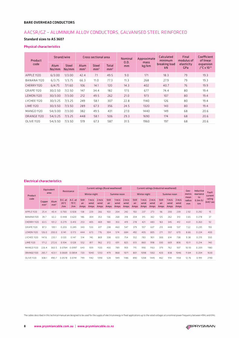
APPLE 1120 6/3.00 1/3.00 42.4 7.1 49.5 9.0 171 18.3 79 19.3
BANANA 1120 6/3.75 1/3.75 66.3 11.0 77.3 11.3 268 27.9 79 19.3
CHERRY 1120 6/4.75 7/1.60 106 14.1 120 14.3 402 40.7 76 19.9
GRAPE 1120 30/2.50 7/2.50 147 34.4 182 17.5 677 74.4 80 19.4
LEMON 1120 30/3.00 7/3.00 212 49.5 262 21.0 973 107 80 19.4
LYCHEE 1120 30/3.25 7/3.25 249 58.1 307 22.8 1140 126 80 19.4
LIME 1120 30/3.50 7/3.50 289 67.3 356 24.5 1320 143 80 19.4
MANGO 1120 54/3.00 7/3.00 382 49.5 431 27.0 1440 149 68 20.6
ORANGE 1120 54/3.25 7/3.25 448 58.1 506 29.3 1690 174 68 20.6
OLIVE 1120 54/3.50 7/3.50 519 67.3 587 31.5 1960 197 68 20.6
Product code
Equivalent area
ResistanceCurrent ratings (Rural weathered) Current ratings (Industrial weathered)
Geo-metric mean radius
mm
Inductive reactance
to 0.3m Ω/
km
Fault current rating
(kA)2.sec
Winter night Summer noon Winter night Summer noon
Copper mm2
Alum mm2
D.C. at 20°C /km
A.C. at 75°C /km
Still air
Amps
1 m/s wind Amps
2 m/s wind Amps
Still air
Amps
1 m/s wind Amps
2 m/s wind Amps
Still air
Amps
1 m/s wind Amps
2 m/s wind Amps
Still air
Amps
1 m/s wind Amps
2 m/s wind Amps
APPLE 1120 25.4 40.4 0.700 0.928 138 229 266 103 204 242 150 237 273 96 200 239 2.92 0.292 15
BANANA 1120 39.7 63.2 0.448 0.620 186 304 353 136 268 318 204 315 362 125 262 313 3.65 0.278 37
CHERRY 1120 63.5 101.2 0.279 0.413 253 405 469 180 353 419 278 421 483 163 345 412 4.61 0.263 92
GRAPE 1120 87.3 139.1 0.203 0.249 343 533 617 238 460 547 379 557 637 213 448 537 7.22 0.235 193
LEMON 1120 126.0 200.0 0.141 0.173 444 673 776 304 574 684 492 405 805 271 557 670 8.66 0.224 400
LYCHEE 1120 147.6 235.1 0.120 0.147 514 745 869 338 633 754 552 783 901 300 614 738 9.38 0.219 550
LIME 1120 171.2 272.6 0.104 0.128 552 817 962 372 691 825 613 860 998 330 669 806 10.11 0.214 740
MANGO 1120 226.4 360.5 0.0784 0.0997 643 939 1120 430 789 959 715 990 1163 379 762 937 10.93 0.209 1180
ORANGE 1120 265.7 423.1 0.0669 0.0854 720 1040 1253 479 868 1071 801 1098 1302 420 838 1046 11.84 0.204 1630
OLIVE 1120 308.1 490.7 0.0578 0.0741 799 1142 1390 528 949 1186 890 1208 1445 462 914 1158 12.76 0.199 2190
AACSR/GZ – ALUMINIUM ALLOY CONDUCTORS, GALVANISED STEEL REINFORCEDStandard sizes to AS 3607
8
BARE OVERHEAD CONDUCTORS
Physical characteristics
www.prysmiancable.com.au | www.prysmiancable.co.nz
The cables described in this technical manual are designed to be used for the supply of electrical energy in fixed applications up to the rated voltages at a nominal power frequency between 49Hz and 61Hz.
Product code
Strand/wire Cross sectional area Nominal O.D. mm
Approximate mass
kg/km
Calculated minimum
breaking load kN
Final modulus of elasticity
GPa
Coefficient of linear
expansion /°C x 10-6Alum
No/mmSteel
No/mmAlum mm2
Steel mm2
Total mm2
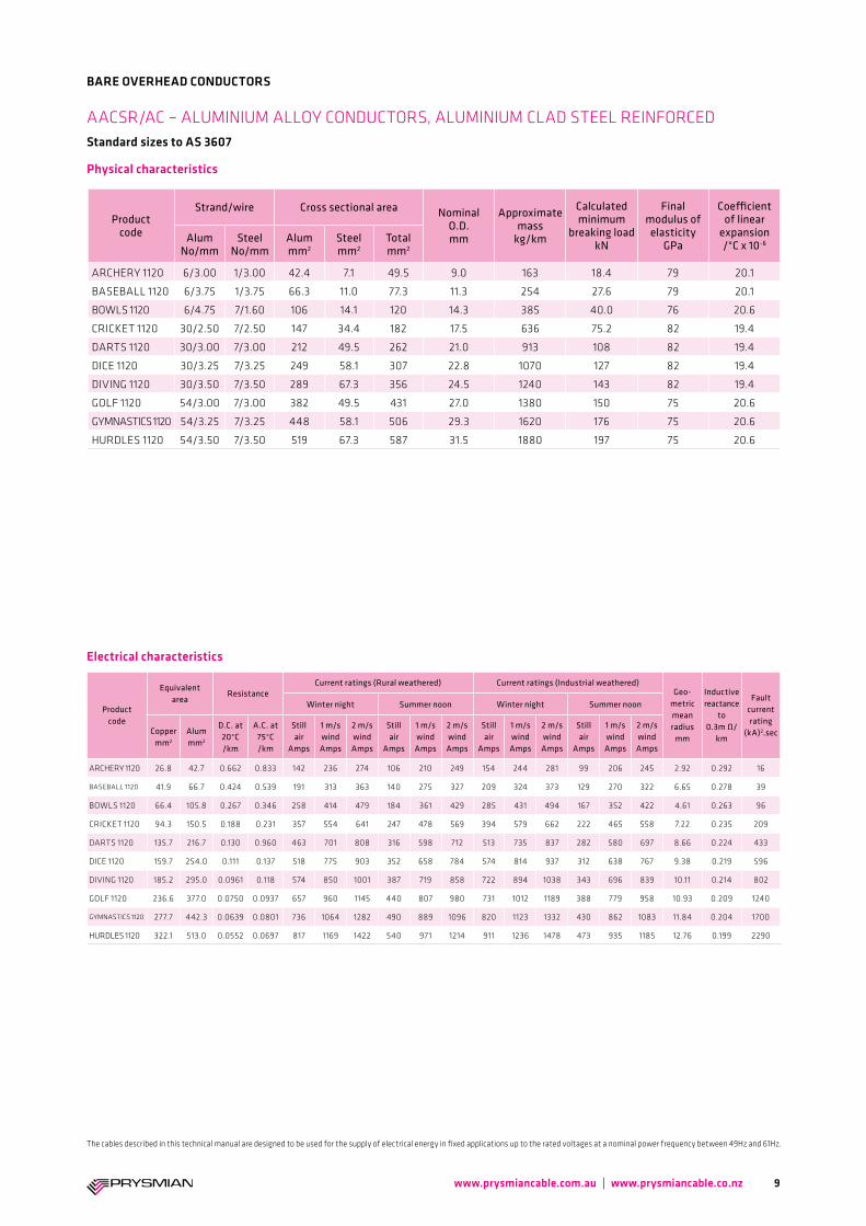
ARCHERY 1120 6/3.00 1/3.00 42.4 7.1 49.5 9.0 163 18.4 79 20.1
BASEBALL 1120 6/3.75 1/3.75 66.3 11.0 77.3 11.3 254 27.6 79 20.1
BOWLS 1120 6/4.75 7/1.60 106 14.1 120 14.3 385 40.0 76 20.6
CRICKET 1120 30/2.50 7/2.50 147 34.4 182 17.5 636 75.2 82 19.4
DARTS 1120 30/3.00 7/3.00 212 49.5 262 21.0 913 108 82 19.4
DICE 1120 30/3.25 7/3.25 249 58.1 307 22.8 1070 127 82 19.4
DIVING 1120 30/3.50 7/3.50 289 67.3 356 24.5 1240 143 82 19.4
GOLF 1120 54/3.00 7/3.00 382 49.5 431 27.0 1380 150 75 20.6
GYMNASTICS 1120 54/3.25 7/3.25 448 58.1 506 29.3 1620 176 75 20.6
HURDLES 1120 54/3.50 7/3.50 519 67.3 587 31.5 1880 197 75 20.6
Product code
Equivalent area
ResistanceCurrent ratings (Rural weathered) Current ratings (Industrial weathered)
Geo-metric mean radius
mm
Inductive reactance
to 0.3m Ω/
km
Fault current rating
(kA)2.sec
Winter night Summer noon Winter night Summer noon
Copper mm2
Alum mm2
D.C. at 20°C /km
A.C. at 75°C /km
Still air
Amps
1 m/s wind Amps
2 m/s wind Amps
Still air
Amps
1 m/s wind Amps
2 m/s wind Amps
Still air
Amps
1 m/s wind Amps
2 m/s wind Amps
Still air
Amps
1 m/s wind Amps
2 m/s wind Amps
ARCHERY 1120 26.8 42.7 0.662 0.833 142 236 274 106 210 249 154 244 281 99 206 245 2.92 0.292 16
BASEBALL 1120 41.9 66.7 0.424 0.539 191 313 363 140 275 327 209 324 373 129 270 322 6.65 0.278 39
BOWLS 1120 66.4 105.8 0.267 0.346 258 414 479 184 361 429 285 431 494 167 352 422 4.61 0.263 96
CRICKET 1120 94.3 150.5 0.188 0.231 357 554 641 247 478 569 394 579 662 222 465 558 7.22 0.235 209
DARTS 1120 135.7 216.7 0.130 0.960 463 701 808 316 598 712 513 735 837 282 580 697 8.66 0.224 433
DICE 1120 159.7 254.0 0.111 0.137 518 775 903 352 658 784 574 814 937 312 638 767 9.38 0.219 596
DIVING 1120 185.2 295.0 0.0961 0.118 574 850 1001 387 719 858 722 894 1038 343 696 839 10.11 0.214 802
GOLF 1120 236.6 377.0 0.0750 0.0937 657 960 1145 440 807 980 731 1012 1189 388 779 958 10.93 0.209 1240
GYMNASTICS 1120 277.7 442.3 0.0639 0.0801 736 1064 1282 490 889 1096 820 1123 1332 430 862 1083 11.84 0.204 1700
HURDLES 1120 322.1 513.0 0.0552 0.0697 817 1169 1422 540 971 1214 911 1236 1478 473 935 1185 12.76 0.199 2290
AACSR/AC – ALUMINIUM ALLOY CONDUCTORS, ALUMINIUM CLAD STEEL REINFORCEDStandard sizes to AS 3607
Electrical characteristics
9
BARE OVERHEAD CONDUCTORS
Physical characteristics
www.prysmiancable.com.au | www.prysmiancable.co.nz
The cables described in this technical manual are designed to be used for the supply of electrical energy in fixed applications up to the rated voltages at a nominal power frequency between 49Hz and 61Hz.
Product code
Strand/wire diameter No/mm
Nominal C.S.A. mm2
Nominal O.D. mm
Approximate Mass
kg/km
Calculated minimum
breaking load kN
Final modulus of elasticity
GPa
Coefficient of linear expansion
/°C x 10-6
7100HDCU 7/1.00 5.5 3.00 49.3 2.32 124 17
7125HDCU 7/1.25 8.6 3.75 76.9 3.59 124 17
7175HDCU 7/1.75 17 5.25 151 6.89 124 17
7200HDCU 7/2.00 22 6.00 197 8.89 124 17
7275HDCU 7/2.75 42 8.25 375 16.2 124 17
7350HDCU 7/3.50 67 10.5 607 25.4 124 17
7375HDCU 7/3.75 77.28 11.3 696 28.8 124 17
19175HDCU 19/1.75 46 8.75 413 18.3 124 17
19200HDCU 19/2.00 60 10.0 538 23.6 124 17
19275HDCU 19/2.75 113 13.8 1020 43.1 124 17
19300HDCU 19/3.00 134 15.0 1210 50.8 124 17
37175HDCU 37/1.75 89 12.3 806 35.6 124 17
37225HDCU 37/2.25 147 15.8 1331 57.6 124 17
37250HDCU 37/2.50 182 17.5 1640 70.3 124 17
37275HDCU 37/2.75 220 19.3 1990 83.9 124 17
37300HDCU 37/3.00 262 21.0 2370 98.9 124 17
61275HDCU 61/2.75 362 24.8 3280 138 124 17
Product code
Equivalent area
ResistanceCurrent ratings (Rural weathered) Current ratings (Industrial weathered)
Geo-metric mean radius
mm
Inductive reactance
to 0.3m Ω/
km
Fault current rating
(kA)2.sec
Winter night Summer noon Winter night Summer noon
Copper mm2
Alum mm2
D.C. at 20°C /km
A.C. at 75°C /km
Still air
Amps
1 m/s wind Amps
2 m/s wind Amps
Still air
Amps
1 m/s wind Amps
2 m/s wind Amps
Still air
Amps
1 m/s wind Amps
2 m/s wind Amps
Still air
Amps
1 m/s wind Amps
2 m/s wind Amps
7100HDCU 7/1.00 8.68 3.25 3.93 46 84 98 38 77 91 49 86 100 36 76 91 1.09 0.354 0.7
7125HDCU 7/1.25 13.6 2.09 2.53 62 111 130 50 101 120 67 113 132 48 100 119 1.36 0.340 1.6
7175HDCU 7/1.75 26.6 1.060 1.28 98 170 198 77 154 182 105 174 202 73 152 180 1.90 0.319 6.0
7200HDCU 7/2.00 34.7 0.815 0.986 117 201 234 91 181 214 126 206 238 86 178 212 2.18 0.311 10
7275HDCU 7/2.75 65.3 0.433 0.524 179 299 348 135 267 316 194 309 356 126 262 312 2.99 0.291 37
7350HDCU 7/3.50 106 0.268 0.325 247 405 470 182 258 425 270 419 483 168 351 419 3.81 0.275 98
7375HDCU 7/3.75 121 0.233 0.283 272 444 515 200 392 465 298 460 529 184 384 459 4.08 0.271 126
19175HDCU 19/1.75 71.7 0.395 0.479 191 318 370 143 283 336 208 328 379 133 278 331 3.31 0.284 45
19200HDCU 19/2.00 93.6 0.303 0.367 228 376 437 169 333 395 249 389 448 156 327 390 3.79 0.276 77
19275HDCU 19/2.75 177 0.160 0.194 351 563 652 251 492 584 386 586 672 228 480 575 5.21 0.256 274
19300HDCU 19/3.00 211 0.134 0.163 396 630 729 280 548 651 437 656 752 253 534 640 5.68 0.250 388
37175HDCU 37/1.75 139 0.203 0.247 299 485 562 217 426 505 328 503 578 198 416 498 4.70 0.262 170
37225HDCU 37/2.25 230 0.123 0.150 422 666 771 295 578 687 466 695 795 266 563 675 6.05 0.246 465
37250HDCU 37/2.50 284 0.0996 0.122 490 762 880 340 657 781 542 796 910 305 640 767 6.72 0.240 710
37275HDCU 37/2.75 344 0.0823 0.101 561 860 993 386 738 878 621 900 1028 345 717 861 7.39 0.234 1040
37300HDCU 37/3.00 409 0.0691 0.0857 635 961 1109 434 820 977 703 1008 1150 387 796 957 8.06 0.228 1470
61275HDCU 61/2.75 566 0.0500 0.0632 799 1182 1393 539 999 1194 888 1244 1446 477 967 1168 9.56 0.218 2820
Electrical characteristics
HDCU – HARD DRAWN COPPER CONDUCTORS Standard sizes to AS 1746
Physical characteristics
10
BARE OVERHEAD CONDUCTORS
www.prysmiancable.com.au | www.prysmiancable.co.nz
The cables described in this technical manual are designed to be used for the supply of electrical energy in fixed applications up to the rated voltages at a nominal power frequency between 49Hz and 61Hz.

Conductor designation
Conductor description
Australian standard
Related standardsIEC
UK US Europe
AAC All aluminium conductor AS 1531 BS 215-1 ASTM B231 DIN 48201-5 61089 A1
AAAC All aluminium alloy conductor AS 1531 BS 3242 ASTM B399 DIN 48201-6 61089 A2/A3
ACSR/GZ Aluminium conductor, galvanised steel reinforced AS 3607 BS 215-2 ASTM B232 DIN 48204 61089 A1/S1A
ACSR/AC Aluminium conductor, aluminium clad steel reinforced AS 3607 BS 215-2 ASTM B549 DIN 48200-8
SC/GZ Galvanised steel conductor AS 1222-1 ASTM A363
SC/AC Aluminium clad steel conductor AS 1222-2 ASTM B416 DIN 48201-8
HD copper Hard drawn copper conductor AS 1746 ASTM B8 DIN 48201-1
To convert from Multiply by AWG = mm2
inch² to mm² 645.16 4/0 107.2
cmil to mm² 0.0005067 3/0 85.0
lbf to kN 0.004448 2/0 67.4
Kips to kN 4.448 0 53.2
Tons/sq in to GPa 0.01544 1 42.4
pounds/sq in to MPa 0.0068948 2 33.6
lbs/1000 yd to kg/km 0.49605 3 26.7
lbs/mile to kg/km 0.28185 4 21.1
lbs/1000 yd to kg/km 0.62137 6 13.3
OVERHEAD CONDUCTOR STANDARDS
Overhead conductors in common use around Australia are specified in Australian standards. The most common international standard which may be specified are British, US, DIN, or IEC standards, which are listed in the following table.
MATERIALS USED IN OVERHEAD CONDUCTORS
Conductor materials used include aluminium and aluminium alloy, copper and galvanised or aluminium clad steel. Alumini-um wires in all aluminium conductors (AAC) and aluminium conductors, steel reinforced (ACSR) are manufactured from high purity electrical grade aluminium. Conductor wires are drawn from continuously cast aluminium rod having extremely uniform physical and electrical properties. Aluminium alloy wires may be used in all aluminium alloy conductors (AAAC) and aluminium alloy conductor steel reinforced (AACSR). The alloy predominantly used in Australia is alloy 1120, which attains greater strength than conventional AAC by controlled additions of copper and magnesium, with only a very small increase in electrical resistivity. International standards specify other aluminium alloys such as alloy 6201, a heat treatable al-loy with additions of magnesium and silicon. This material did not attain extensive use and is no longer offered in Australia because of the increased processing costs associated with heat treatment, the greater increase in electrical resistivity compared to alloy 1120 and the lack of practical value for its increased strength in most Australian climatic conditions.
Copper wires used in hard drawn copper conductors are manu-factured from electrolytic tough pitch, high conductivity copper. Copper conductors are now rarely used for bare overhead transmission and find their main application as Catenary in railway electrification work. Galvanised steel wires are used in the manufacture of ACSR/GZ and SC/GZ. The wires are made from fully killed steel to AS 1442 and are galva-nised by a hot dipping process to give a coating between 200 and 260 g/m² Aluminium clad steel wires use the same base steel as galvanised wires, and are used in the manufacture of ACSR/AC and SC/AC. The wires have an aluminium coating of not less than 5% of the wire diameter.
The ASTM standards are specified in imperial measurements. The following table gives conversions for the more common units used.
General information
11www.prysmiancable.com.au | www.prysmiancable.co.nz
Phase conductors
The selection of the optimum material for overhead lines is dictated by the conditions of each installation. Some of these considerations are:
Required current carrying capacity
Length of line: electrical losses.
Climatic: prevailing weather conditions
Corrosion: proximity to sea or polluted atmosphere
Physical: maximum span and tower/pole height.
In normal Australian conditions, AAAC 1120 has been the material of choice for the past 15 years for large transmis-sion lines. This is because of all materials available it repre-sents the best compromise between conductor strength, electrical properties and cost. Whilst some materials or combinations of materials are available with higher strength to weight ratios, it is often not practical to use this extra strength to achieve reduced sag because of problems with Aeolian vibration when lines are strung over certain critical tensions. AAC conductors are generally used in situations where the conductor spans are relatively short, and thus their lesser strength is not so important. Their greatest ap-plication is usually in the smaller power distribution applica-tions. The extra strength offered by ACSR conductors may be needed in situations where a line is being constructed in an area that has extreme climatic conditions. In these situa-tions the extra strength may be required to withstand the heavier conductor loads resulting from cyclonic winds or ice and snow loading. Where no specific information exists on the prevailing climate, specifiers are referred to ASNZS 7000, which includes details of wind velocity for each region of Australia. ACSR or AACSR may also be prefrrered if the proposed design includes very long spans between towers. For steel reinforced conductors, the decision to use galva-nized or aluminium clad steel is most often dictated by the assessment of the need of the extra corrosion protection offered by aluminium clad wire against its greater cost.
Many transmission lines in close proximity to the coast require this extra corrosion resistance if steel is specified, but in drier inland areas, a galvanized reinforced conductor with the steel core suitably protected with high dropping point grease is satisfactory. The higher conductivity of aluminium clad steel means that an ACSR conductor with this material will have a higher current carrying capacity that an other-wise identical conductor with galvanised reinforcement.
Earthwire
Because earthwires are usually required to have less sag than the phase conductors, they are normally either ACSR or all steel construction. The size of the earthwire will be dictated by the fault current requirement of the line and/ or the level of isoceraunic activity in the area. The choice between galva-nised and aluminium clad steel is made under the same crite-ria as phase conductors, though recently, most major lines have specified aluminium clad steel. Many new lines con-structed recently have included optical fibre in at least one of the earthwires. This conductor, termed OPGW (Optical groundwire) provides the means for internal line protection, communication and control, and also opens up the possibility of an additional revenue stream through leasing of fibre to third parties. OPGW containing from 6 to 144 fibres has been installed in Australia. Because of the need to guarantee a long service life and the high cost of replacement, nearly all OPGWs include aluminium clad steel in their constructions. Because of changing circumstances such as reduced access to microwave frequencies and the possibility of leasing fibre to third parties, some Australian authorities have retrofitted OPGW onto existing transmission lines. All OPGW is currently being produced oversees, and most manufacturers produce OPGW to international IEC or IEEE standards. This will nor-mally guarantee compliance to related Australian standards.
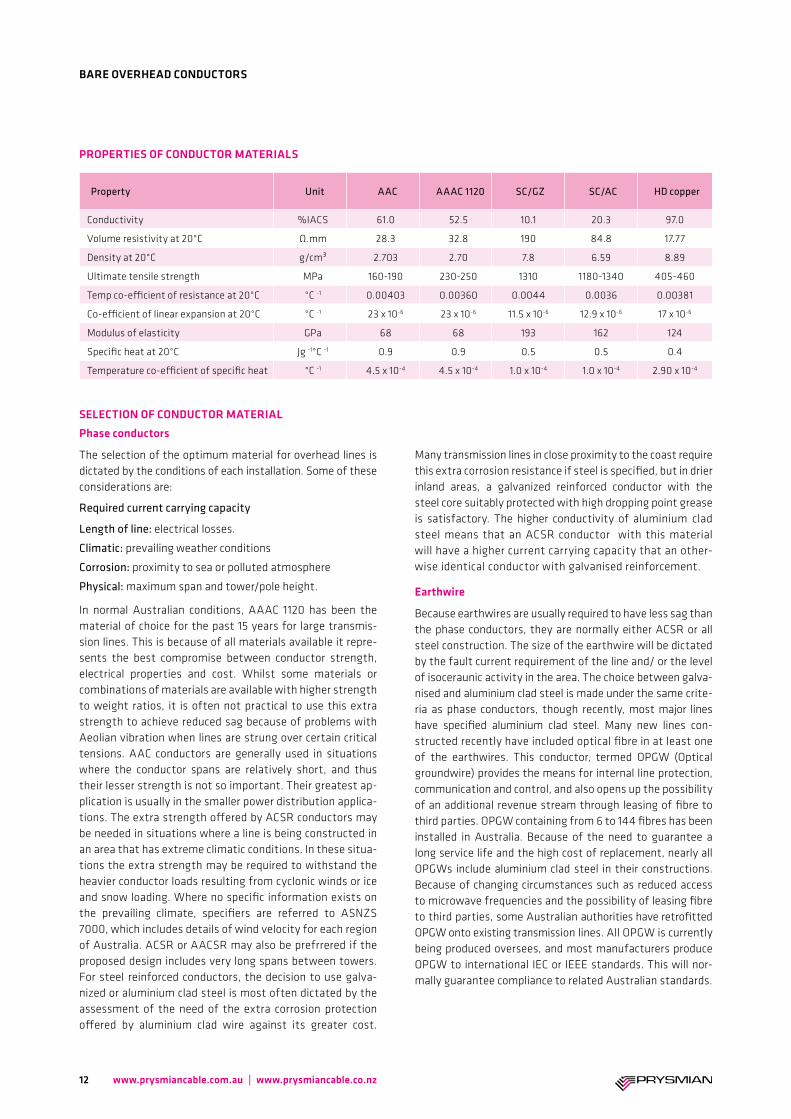
Property Unit AAC AAAC 1120 SC/GZ SC/AC HD copper
Conductivity %IACS 61.0 52.5 10.1 20.3 97.0
Volume resistivity at 20°C Ω.mm 28.3 32.8 190 84.8 17.77
Density at 20°C g/cm³ 2.703 2.70 7.8 6.59 8.89
Ultimate tensile strength MPa 160-190 230-250 1310 1180-1340 405-460
Temp co-efficient of resistance at 20°C °C -1 0.00403 0.00360 0.0044 0.0036 0.00381
Co-efficient of linear expansion at 20°C °C -1 23 x 10-6 23 x 10-6 11.5 x 10⁻⁶ 12.9 x 10⁻⁶ 17 x 10-6
Modulus of elasticity GPa 68 68 193 162 124
Specific heat at 20°C Jg -1°C -1 0.9 0.9 0.5 0.5 0.4
Temperature co-efficient of specific heat °C -1 4.5 x 10⁻⁴ 4.5 x 10⁻⁴ 1.0 x 10⁻⁴ 1.0 x 10⁻⁴ 2.90 x 10⁻⁴
PROPERTIES OF CONDUCTOR MATERIALS
SELECTION OF CONDUCTOR MATERIAL
12
BARE OVERHEAD CONDUCTORS
www.prysmiancable.com.au | www.prysmiancable.co.nz
ERECTION OF CONDUCTORS AND EARTHWIRE
Care should be exercised during erection of conductors to prevent the loosening of strands an the picking up of foreign inclusions, such as ground matter between the strands. Extreme looseness can result in the condition known as bird-caging, which can be the result of one of the following:
• Inadequate control of tension during unwinding.
• Bending conductor sharply through the use of under diameter sheaves or rollers.
• Unwinding conductor with the tail end of the conductor still firmly attached to the drum.
• Use of an incorrectly reeved tensioner.
Bending radius of bare overhead conductors.
In order to prevent distortion to the wires in each conductor layer, and to prevent twisting and loosening of wires, it is recommended that sheave diameters should be not less than 20 times the conductor diameter.
SAGS AND TENSIONS
A conductor strung between two supports will naturally assume a catenary shape. However for most normal spans, the shape is very close to that of a parabola.
Using the parabolic form, the sag in a level span may be ex-pressed as:
D = WL 8T
where: D = sag (m) L = span (m) W = mass/unit length of the conductor (kg/m) T = conductor tension (kgf)
In arriving at a sag value, two important values are normally considered.
1. Maximum working tension:This is the maximum tension exerted on the conductor at the time of the most adverse climatic conditions predicted for the installation area. e.g. maximum wind plus ice load and minimum temperature. This is normally taken at 50% of the conductor breaking load (CBL).
2. Everyday tension:This is the condition that the conductor will be expected to be under for the majority of time, and is generally nomi-nated as a conductor tension at a specified temperature. E.g. 20% of CBL at 25°C. This is referred to as the everyday tension (EDT).
The every day tension should be set so that under the expected worst climatic conditions, the maximum working tension is not exceeded at any time during the conductors installed life.
The maximum sag will occur when the conductor is operating at its maximum operating temperature (normally 75°C). This condition will be that of minimum ground clearance. Many commercial programmes are now available to perform sag tension calculations. However, the accuracy in these pro-grammes is dependant on the accuracy of the conductor physical parameters which must be supplied to the calculations to be made. Information to be input will include conductor breaking load, 10 year creep, modulus of elasticity and coeffi-cient of thermal expansion.
A detailed analysis of sag and tension calculations may be found in Appendix S of AS/NZA 7000.
CONDUCTOR CREEP
Metallurgical creep occurs in all overhead conductors. Over a period of time this results in slightly increased conductor sag.
The effects of creep can be minimised by pre stressing the conductor. This involves over tensioning the conductor for a short period of time before the final sagging operations are carried out. The initial high tension will remove a large propor-tion of the creep, minimising the amount which later occurs in the life of the conductor.
MODULUS OF ELASTICITY
The modulus of elasticity of an overhead conductor is depend-ant on the conductor material, plus the construction and conditions of manufacture. The modulus is another parameter which must be quantified if accurate sag tension predictions are to be made. Where available the values for modulus in this catalogue with an asterisk are based on the calculated modulus, which is normally slightly higher than the actually measured value.
CONDUCTOR TESTING
Prysmian Cables maintains fully equipped testing facilities capable of testing full conductor breaking load, modulus, of elasticity and co-efficient of thermal expansion. Prysmian can also perform creep tests at both room and elevated temperature which will provide the customer with 10 year creep values.
Technical information – Mechanical
13
BARE OVERHEAD CONDUCTORS
www.prysmiancable.com.au | www.prysmiancable.co.nz
CALCULATION OF CONDUCTOR ELECTRICAL PROPERTIES
Equivalent aluminium area: This term denotes the area of a solid aluminium rod having the same resistance as the stranded conductor. For a homog-enous conductor this is obtained by multiplying the area of one wire by that conductor’s stranding constant and then by the ratio of the resistivity of aluminium to that of the conduc-tor material. For aluminium clad steel reinforced conductors, the equivalent aluminium area of each component is calculat-ed and then added together. For construction which are galva-nized steel reinforced, the steel component is ignored.
Mass: A similar technique is used to calculate conductor mass, whereby a mass constant, which includes allowances for ma-terial density as well as wire over length is used. The area of one wire is simply multiplied by the mass constant for a homogenous conductor.
DC resistance: The resistance is obtained by multiplying the resistance of a single wire by the appropriate resistance constant. For alu-minium clad steel reinforced conductor the resistance is calculated by summing in parallel the resistances of the alu-minium and steel components.
e.g. 1 = 1 + 1 R R1 R2
For galvanised steel reinforced conductor the contribution of the steel wires is not considered.
A.C. resistance: The alternating current resistance is greater than the direct current resistance because of:
1. Skin effect:with alternating current, there is a greater proportion of current flowing in the surface layers of the conductor than in the conductor body. This results in an increase in conductor resistance.
2. Magnetic effect of steel core:in ACSR conductor, the spiralling effect of the current in the aluminium later gives rise to axial magnetic fields which lead to power losses in the steel core. With conductors having an even number of aluminium layers the magnetic effects of each layer tend to cancel, and the effect is negligible. However, with an odd number of layers, the ef-fect can be considerable.
The AC resistance figures in the data tables have been corrected for skin effect and core magnetization. It is nec-essary to determine the AC resistance of a conductor to accurately calculate its current rating.
CURRENT RATINGS
Factors affecting current rating of overhead conductors:
1. Emissivity:The standard value for bright new conductor is taken as 0.3. After weathering, the emissivity increases up to a maximum value of 0.5 for a rural weathering and 0.8 in an industrial / polluted environment. Small changes in Emissivity have little effect on current rating.
2. Ambient temperature:The standard generally adopted for Australia is 35°C, for summer noon conditions, leaving a 40°C temperature rise for the purposes of summer current rating calculation. Similarly 10°C is used for winter night conditions (ie 65°C maximum temperature rise).
3. Absorbance:The standard value for a bright conductor is 0.6. Weather-ing will reduce this value to 0.5 for a rural environment with a corresponding increase in current rating.
4. Solar radiation:The solar radiation intensity changes with the altitude of the sun and the clearness of the sky. A value of 1000 W/m² is taken as the standard for direct solar radiation and 100 W/m² for diffuse solar radiation for summer noon conditions as be-ing appropriate for general conditions throughout Australia.
5. Wind angle:Ratings are generally based on the wind being at right angles to the phase conductors. Current ratings are reduced by over 30% if the wind is blowing along the axis of the conductor.
6. Wind velocity:A minimum current rating occurs with zero wind speed and heat losses occurring by convection only. Current carrying capacities have been provided for the theoretical extreme condition of still air(1) and for wind speeds of 1.0 m/s(2) and 2.0 m/s(3). Current ratings are substantially increased at higher wind velocities.
The current ratings quoted in this catalogue have been calcu-lated according the method described in the ESAA publication D(b)5-1988. The standard conditions adopted are as follows:
Summer day Winter night
Air temperature 35°C 10°C
Temperature rise 40°C 65°C
Emissivity 0.5 0.5
Absorbance 0.5 -
Direct solar radiation intensity 1000 W/m² Nil
Diffuse solar radiation intensity 100 W/m² Nil
Wind velocity (1) Still 0 m/s 0 m/s
Wind velocity (2) 1.0 m/s 1.0 m/s
Wind velocity (3) 2.0 m/s 2.0 m/s
Ground reflectance (Albedo) 0.2 0.2
Angle of wind 90° 90°
Technical information – Electrical
14
BARE OVERHEAD CONDUCTORS
www.prysmiancable.com.au | www.prysmiancable.co.nz
GEOMETRIC MEAN RADIUS
The GMR represents the radius of an infinitely thin tube having the same inductance under the same current loading as the conductor.
The GMR is expressed as: GMR = 0.5 x D x Kg
where: GMR = geometric mean radius (m) D = overall conductor diameter (m) Kg = layer factor
The layer factor depends on the type of conductor and layer geometry. The layer factor for single layer ACSR conductors varies with conductor size and current loading, and must be experimentally determined.
Conductor stranding Layer factor (Kg )
ACSR conductors
6/1, 4/3, 3/4 Varies
22/7 0.7949
26/7 0.8116
30/7 0.8250
45/7 0.7939
54/7 0.8099
54/19 0.8099
All aluminium conductors
7W 0.7256
19W 0.7577
37W 0.7678
61W 0.7722
91W 0.7743
INDUCTIVE REACTANCE
The inductive reactance of a conductor is calculated using the concepts of geometric mean radius (GMR) and geometric mean distance (GMD). Whilst no energy loss is directly related to inductive reactance, a slight increase in the I²R loss occurs in the conductors because of it.
The total inductive reactance (X) is the sum of:
Xa + Xd where:
Xa = That due to both the internal magnetic flux and that external to the conductor to a nominated radius.
Xd = That due to both the magnetic flux surrounding the conductor from the nominated radius out to the equivalent return conductor.
Xa = 0.1736 log ohm/kmf60
aGMR
Where:a = nominated radius, normally 0.3048 m (1 ft) GMR = geometric mean radius (m) Xa = inductive reactance (ohm/km) f = frequency (Hz)
and
Xa = 0.1736 log ohm/kmf60
GDMa
Where: GMR = geometric mean distance (m)
For a 3 phase transmission line: GMD = 3√(d1 × d2 × d3) where d1, d2 and d3 are conductor separations (m)
As the inductive reactance resulting from the equivalent return conductor (Xd) is dependant on line design, the data sheets included in this catalogue only quote the inductive reactance from magnetic flux (Xa) to a 0.3048 metre (1 foot) radius. Where inductive reactance and GMR are nominated for a single layer ACSR conductor, the values are based on those published by the Aluminium Association, and maybe consid-ered as accurate to 3%.
15
BARE OVERHEAD CONDUCTORS
www.prysmiancable.com.au | www.prysmiancable.co.nz
FAULT CURRENT RATING
The fault current rating is calculated under the premise that the fault duration will be short, less than one second and that for such periods it may be assumed that no heat will be dissipated from the conductor.
Within the initial and final temperature constraints, the one second fault rating of a conductor (F), expressed in KA².sec may be approximated by the following formula:
F = InArR x 106
A2DC20 1+Ac – 20 T2 – 20 +
T2 – 20 +
1
1
T1+T2
2 Ar
Ar
Where: T2 = final temperature °C T1 = initial temperature °C Ar = temperature coefficient of resistance °C -1 R = volume resistivity at 20°C Ω.mm D = density g/mm³ C20 = specific heat at 20°C Jg-1°C -1 AC = temperature coefficient of specific heat °C -1 A = conductor cross sectional area mm²
The fault ratings published in this catalogue are based on initial temperatures of 50°C for phase conductors and 35°C for all steel conductors, which are normally used as earthwires.
The final temperatures are 160°C for AAC, AAAC and ASCR and 400°C for SC/GZ and SC/AC.
These temperatures are those recommended in AS/NZA 7000.
VOLTAGE DROP
Approximate voltage drop may be calculated from the im-pedance of the transmission line.
Z = √(R² × X²)
Where: Z = impedance (ohm/km) R = AC resistance (ohm/km) X = total inductive reactance (ohm/km)
and
V = IZ
Where: V = voltage drop (volts/km) I = current (amps)
Because the total inductive reactance (X) component of the above formula is dependant on line design, subsequently no figures for voltage drop are published in this catalogue.
16
BARE OVERHEAD CONDUCTORS
www.prysmiancable.com.au | www.prysmiancable.co.nz
Whilst every care has been taken in the preparation of this publication, the Prysmian Group take no responsibility for any errors and or omissions. This booklet is in-tended as a guide only and reference must be made by any person using this booklet to the appropriate Australian/New Zealand Standard and or to local electricity supply authority rulings. The company reserves the right to make changes in product without notice. All rights reserved. Subject to change without notice.
Referenced documentsAS 1531 - 1991 Conductors – Bare Overhead – Aluminium And Aluminium Alloy
AS 3607 - 1989 Conductors – Bare Overhead, Aluminium And Aluminium Alloy – Steel Reinforced
AS 1746 - 1991 Conductors – Bare Overhead – Hard-Drawn Copper
AS 1222.1 - 1992 Steel Conductors And Stays – Bare Overhead Part 1: Galvanized (SC/GZ)
AS 1222.2 - 1992 Steel conductors And Stays – Bare Overhead Part 2: Aluminium Clad (SC/AC)
AS/NZS 7000 Overhead Line Design – Detailed Procedures
ESAA HB D(b)5-1988 Current Rating Of Bare Overhead Line Conductors
IEC 1597 - 1995 Overhead Electrical Conductors – Calculation Methods For Stranded Bare Conductors
IEEE Std 524 - 1980 IEEE guide to the installation of overhead transmission line conductors Aluminium Electrical Conductor Handbook, The Aluminium Association, 1971
17
BARE OVERHEAD CONDUCTORS
www.prysmiancable.com.au | www.prysmiancable.co.nz
Notes
18 www.prysmiancable.com.au | www.prysmiancable.co.nz
Notes
19www.prysmiancable.com.au | www.prysmiancable.co.nz
Linking the future
© A
ll rights reserved by Prysmian Group 20
15 | 10
Prysmian Australia Pty Ltd
1 Heathcote Road, Liverpool 2170 NSW, Australia Ph: 1300 300 304 Fx: 1300 300 307 E-mail: [email protected]
www.prysmiancable.com.au
Prysmian New Zealand Ltd
30 Binsted Road, New Lynn 0640 Auckland, New Zealand Ph: (09) 827 3109 Toll Free: 0800 492 225 E-mail: [email protected]
www.prysmiancable.co.nz


![IS 6162-1 (1971): Paper-Covered Aluminium Conductors, Part I: Round ... · I: Round Conductors [ETD 33: Winding Wire] Title: IS 6162-1 (1971): Paper-Covered Aluminium Conductors,](https://img.pdfslide.net/doc/110x75/5f0fc0267e708231d445b387/is-6162-1-1971-paper-covered-aluminium-conductors-part-i-round-i-round.jpg)