Embed Size (px)
Citation preview
AIRCO BERKELEY TRANSFER STATION OFFICE
1201 Second Street Berkeley, CA 94710
Specifications No. 19-11274
PROJECT MANUAL
June 5, 2019 BID SET
Owner:
Department of Public Works
2180 Milvia Street Berkeley, CA 94704 Phone 510/981-6300 Fax 510/981-6320
Architect: ELS Architecture and Urban Design
2040 Addison Street Berkeley, CA 94704 Phone 510.549.2929 Fax 510.843.3304
www.elsarch.com

AIRCO BERKELEY TRANSFER STATION OFFICE 1201 SECOND STREET BERKELEY, CA 94710
Specifications No. 19-11274
06.05.19 00 01 10 - 1 Table of Contents
00 01 10
TABLE OF CONTENTS
00 01 01 Project Title Page 00 01 10 Table of Contents
DIVISION 01 - GENERAL REQUIREMENTS To Be Supplied by the City DIVISION 02 - EXISTING CONDITIONS
Section 02 41 16 Selective Building Demolition DIVISIONS 03 THROUGH 05 Not Used DIVISION 06 - WOOD, PLASTICS, AND COMPOSITES
Section 06 10 00 Rough Carpentry Section 06 64 00 Plastic Paneling
DIVISION 07 - THERMAL AND MOISTURE PROTECTION
Section 07 21 01 Building Insulation Section 07 92 00 Joint Sealants
DIVISION 08 - OPENINGS
Section 08 11 15 Steel Doors and Frames Section 08 14 00 Wood Doors Section 08 71 00 Door Hardware Section 08 80 00 Glazing
DIVISION 09 - FINISHES
Section 09 29 00 Gypsum Board Section 09 51 00 Acoustical Ceilings Section 09 65 00 Resilient Flooring Section 09 68 13 Tile Carpeting Section 09 90 00 Painting and Coating Section 09 97 25 Vapor Emission Treatment Systems
DIVISION 10 - SPECIALTIES
Section 10 14 00 Signage Section 10 28 13 Toilet Accessories
DIVISIONS 11 THROUGH 21
Not Used

AIRCO BERKELEY TRANSFER STATION OFFICE 1201 SECOND STREET BERKELEY, CA 94710
Specifications No. 19-11274
06.05.19 00 01 10 - 2 Table of Contents
This Page Intentionally Left Blank
AIRCO BERKELEY TRANSFER STATION OFFICE 1201 SECOND STREET BERKELEY, CA 94710
Specifications No. 19-11274
06.05.19 00 01 10 - 3 Table of Contents
DIVISION 22 - PLUMBING
Section 22 00 00 Plumbing Requirements Section 22 05 00 General Plumbing Systems Section 22 05 12 Plumbing Pipe and Fittings Section 22 40 00 Plumbing Fixtures
DIVISION 23 - HEATING, VENTILATING, AND AIR CONDITIONING (HVAC)
Section 23 00 00 Basic Mechanical Requirements Section 23 05 93 Testing, Adjusting and Balancing Section 23 07 00 HVAC Insulation Section 23 31 00 Ductwork Section 23 33 00 Ductwork Accessories Section 23 37 00 Air Outlets and Inlets
DIVISIONS 24 THROUGH 25
Not Used DIVISION 26 - ELECTRICAL
Section 26 00 00 Electrical DIVISIONS 27 THROUGH 49
Not Used
END OF TABLE OF CONTENTS

AIRCO BERKELEY TRANSFER STATION OFFICE 1201 SECOND STREET BERKELEY, CA 94710
Specifications No. 19-11274
06.05.19 00 01 10 - 4 Table of Contents
This Page Intentionally Left Blank
AIRCO BERKELEY TRANSFER STATION OFFICE 1201 SECOND STREET BERKELEY, CA 94710
Specifications No. 19-11274
06.05.19 02 41 16 - 1 Selective Building Demolition
SECTION 02 41 16
SELECTIVE BUILDING DEMOLITION PART 1 - GENERAL 1.01 SUMMARY
A. Section Includes: Selective demolition of building elements. 1. Protect items in place as indicated on the Drawings. 2. Demolish/remove items as indicated on the Drawings. 3. Remove/salvage and remove/reinstall items as indicated on the Drawings.
B. Drawings and general provisions of the Contract, including General and Supplementary
Conditions and Division 01 Specification Sections, apply to this Section. 1.02 REFERENCES
A. ANSI - American National Standards Institute 1. A10.6 - Safety Requirements for Demolition Operations.
B. EPA - Environmental Protection Agency
C. NFPA - National Fire Protection Association
1. 241 - Standard for Safeguarding Construction, Alteration, and Demolition Operations. 1.03 DEFINITIONS
A. Remove: Remove and legally dispose of items except those indicated to be reinstalled, salvaged, or to remain the City’s property.
B. Remove and Salvage: Items indicated to be removed and salvaged remain the City’s
property. Remove, clean, and pack or crate items to protect against damage. Identify contents of containers and deliver to the City’s designated storage area.
C. Remove and Reinstall: Remove items indicated; clean, service, and otherwise prepare
them for reuse; store and protect against damage. Reinstall items in locations indicated.
D. Existing to Remain: Protect construction indicated to remain against damage and soiling during selective demolition. When permitted by the Architect, items may be removed to a suitable, protected storage location during selective demolition and then cleaned and reinstalled in their original locations.
E. Materials Ownership: Except for items or materials indicated to be reused, salvaged,
reinstalled, or otherwise indicated to remain the City’s property, demolished materials shall become the Contractor’s property and shall be removed from the site with further disposition at the Contractor’s option.
1.04 SUBMITTALS
A. Procedures: In accordance with Division 01.
B. Qualification Data: For demolition firm if not provided by Contractor.
AIRCO BERKELEY TRANSFER STATION OFFICE 1201 SECOND STREET BERKELEY, CA 94710
Specifications No. 19-11274
06.05.19 02 41 16 - 2 Selective Building Demolition
C. Pre-demolition Photographs and Details: Show existing conditions in areas where demolition work will be performed, both interior and exterior, including finish surfaces, items to be salvaged, and items to be re-installed, that might be misconstrued as damage caused by demolition operations. Submit before work begins.
D. Inventory of Salvaged Items: After demolition is complete, submit a list of items that have
been removed and salvaged. 1. Include at least one digital photograph of each item, numbered and clearly labeled to
correspond with inventory. 2. Provide written Table of Contents for inventory. 3. Indicate original location(s) of each item or type of item. 4. Indicate whether or not the item is to be re-installed. If it will be re-installed, indicate
repair or restorative work required and location of re-installation.
E. Demolition, Salvage, and Re-Installation Plan as specified.
F. Receipts for recycled materials that include name of licensed recycling company, dollar value, and date.
1.05 DEMOLITION, SALVAGE, AND RE-INSTALLATION PLAN
A. Submit a complete Demolition, Salvage, and Re-Installation Plan detailing procedures and sequence for the following: 1. Removal of existing construction and facilities including all features necessary to
remove portions of the existing building for new work in a safe and controlled manner to ensure stability, weathertightness, and security of the existing building at any given time.
2. Removal, salvage, transportation, storage, and re-installation of items to be re-installed.
3. Submit detailed information on methods and sequencing for accomplishing this work. Employ a Structural Engineer registered in the State of California to develop such methods and demolition sequences.
B. Thoroughly investigate the condition of the existing structures before proceeding with the
Demolition, Salvage, and Re-Installation Plan.
C. The Demolition, Salvage, and Re-Installation Plan shall consist of the following: 1. Detailed sequence of demolition and removal work, with starting and ending dates for
each activity. 2. Interruption of utility services. 3. Coordination for shutoff, capping, and continuation of utility services. 4. Details and locations of temporary and exterior protective measures to ensure that
people, property and improvements to remain will not be endangered or damaged. 5. Access routes for hauling debris and salvaged items from building. 6. Coordinate schedule of activity for hazardous materials removal and other work
contracted directly by the City.
D. In the event that modifications to the Demolition, Salvage, and Re-Installation Plan are required to be submitted for approval, the Contractor shall provide 14 calendar days for the review of substantial procedural and sequence modifications.
E. Review by the Architect and the City of the Demolition, Salvage, and Re-Installation Plan, or
field observations performed by the Architect, will in no way relieve the Contractor of full responsibility for the Demolition, Salvage, and Re-Installation Plan and procedure.
AIRCO BERKELEY TRANSFER STATION OFFICE 1201 SECOND STREET BERKELEY, CA 94710
Specifications No. 19-11274
06.05.19 02 41 16 - 3 Selective Building Demolition
1.06 QUALITY ASSURANCE
A. Demolition Firm Qualifications: A firm with documented specialized experience in demolition work similar in material and extent to that indicated for this Project.
B. Regulatory Requirements: Comply with governing EPA notification regulations before
beginning demolition. Comply with hauling and disposal regulations of authorities having jurisdiction.
C. Standards: Comply with ANSI A10.6 and NFPA 241.
D. Pre-demolition Conference
1. Conduct conference at Project site. Conference shall be attended by Contractor, the City, Architect, demolition contractor if applicable, and others whose work is affected by demolition operations.
2. Pre-demolition photographs and details shall be complete and accepted by Architect before conference takes place.
3. Notify participants a minimum of 48 hours prior to time of conference. 4. Review methods and procedures related to demolition including, but not limited to, the
following: a. Pre-demolition photographs must be complete and acceptable to Architect and
the City. b. Inspect and discuss condition of construction to be demolished. c. Review and finalize Demolition, Salvage, and Re-Installation Plan and verify
availability of demolition personnel, equipment, and facilities needed to make progress and avoid delays.
d. Review and finalize protection requirements. 5. Record discussions of conference and any conflict, incompatibility, or inadequacy.
Furnish a copy of record to each participant. 1.07 TRAFFIC
A. Conduct demolition operations and the removal of debris to ensure minimum interference with streets, walks, and adjacent occupied or used facilities. Do not close or obstruct streets, walks, or other occupied or used facilities without permission from the City, and, where applicable, from other authorities having jurisdiction.
B. Existing pedestrian walks shall be kept open at all times unless otherwise approved by the
City. Any closings or disruptions of existing site circulation, if required, shall be included in the Demolition Plan.
C. Full compensation for temporary vehicular and pedestrian controls shall be considered as
included in the Contract Lump Sum Price and no additional compensation will be allowed for this purpose.
1.08 PROJECT CONDITIONS
A. Conditions existing at time of inspection for bidding purposes will be maintained by the City as far as practical.
B. Coordinate the performance of work in this Section with related or adjacent work.
C. Protection of items should be completed prior to commencement of new construction and
demolition procedures. At the end of working day or during inclement weather, cover work exposed to weather with waterproof coverings, securely anchored.
AIRCO BERKELEY TRANSFER STATION OFFICE 1201 SECOND STREET BERKELEY, CA 94710
Specifications No. 19-11274
06.05.19 02 41 16 - 4 Selective Building Demolition
D. Asbestos and lead paint may be encountered in the Work. If any materials suspected of containing asbestos or lead paint are encountered, do not disturb the materials. Immediately notify the Architect and the City’s Representative.
PART 2 - PRODUCTS 2.01 PROTECTION MATERIALS
A. Polyethylene Sheets: 4 mil.
B. Lumber: Species to be selected by the Contractor, with sizes to fit field conditions. Lumber shall be fire retardant treated.
C. Plywood: 1/2-inch or 3/4-inch fire retardant treated.
D. Soft Fiberboard
1. 1/2-inch Homasote. 2. 1/2-inch NCFR Homasote for exposed locations.
E. Neoprene: 1/4-inch or 1/2-inch strips stock sizes.
F. Polyurethane Foam Sheets: 4-inches thick.
G. “Preservation” Tape: As manufactured by 3M, “Scotch Brand No. 4811”; American Biltrite
Inc.; Surface Armor, or equal.
H. Plastic Film Tape: As manufactured by 3M, “Scotch Brand No. 472”; American Biltrite Inc.; Surface Armor, or equal.
I. Kraft Paper.
J. Accessories: Provide necessary and related parts, fasteners, devices and anchors
required for complete installation. PART 3 - EXECUTION 3.01 EXAMINATION
A. Survey existing conditions and correlate with requirements indicated to determine extent of demolition required.
B. Inventory and record the condition of any items required to be removed and salvaged.
Where appropriate, provide at least one digital photograph.
C. When unanticipated mechanical, electrical, or structural elements are encountered, investigate and measure the nature and extent of the element. Promptly submit a written report to Architect and the City.
D. Perform an engineering survey of condition of existing buildings to determine whether
removing any unanticipated element might result in structural deficiency or unplanned collapse of any portion of structure or adjacent structures during building demolition operations.
AIRCO BERKELEY TRANSFER STATION OFFICE 1201 SECOND STREET BERKELEY, CA 94710
Specifications No. 19-11274
06.05.19 02 41 16 - 5 Selective Building Demolition
E. Hazardous materials will be remediated by the City under separate contract. Coordinate with the City's separate contractor, to ensure that hazardous materials are removed or remediated before proceeding with demolition operations in the affected area.
3.02 PREPARATION
A. Existing Utilities: Locate, identify, disconnect, and seal or cap off indicated utilities to be removed or abandoned. 1. Arrange to shut off indicated utilities with the City and utility companies when
applicable. 2. Do not start demolition work until utility disconnecting and sealing have been
completed and verified in writing.
B. Temporary Shoring: Provide and maintain shoring, bracing, or structural support to preserve stability and prevent unexpected movement or collapse of existing construction. 1. Strengthen or add new supports when required during progress of demolition. 2. All work shall be designed by Contractor's Structural Engineer.
C. Comply with the following:
1. Clean salvaged items of dirt and demolition debris. 2. Make a written inventory of all salvaged items as specified in Part 1, noting original
location, condition, and any significant damage or deficiencies. 3. Pack or crate items after cleaning. Identify contents of containers and number to
correspond with inventory. 4. Store items in a secure area until re-installation or until delivery to the City, as
applicable. 5. Transport items to the City or to new location in building as applicable. 6. Protect items from damage during transport and storage.
3.03 POLLUTION CONTROLS
A. Use water mist, temporary enclosures, and other suitable methods to limit the spread of dust and dirt. Comply with governing environmental protection regulations.
B. Remove and transport debris in a manner that will prevent spillage on adjacent surfaces
and areas.
C. Clean adjacent site areas of dust, dirt, and debris caused by selective demolition operations. Return adjacent areas to condition existing before start of selective demolition.
3.04 INSTALLATION OF PROTECTION
A. General 1. Alternative methods to specified protection may be acceptable if equal or greater
protection is provided. Submit alternative methods to the Architect for review as specified. Do not proceed with alternative methods until specified approvals are secured. Mockups may be required.
2. Protection may be required to remain in place for the duration of the Project. As such, materials shall be installed to provide adequate protection throughout the full extent of construction activities. Repair or reinstall protection as required throughout the duration of construction. Changes to protection shall be proposed to the Architect for approval prior to making changes.
3. All protection assemblies should be self-supporting and self bracing, and secured at the base, unless otherwise noted.
AIRCO BERKELEY TRANSFER STATION OFFICE 1201 SECOND STREET BERKELEY, CA 94710
Specifications No. 19-11274
06.05.19 02 41 16 - 6 Selective Building Demolition
B. Existing Facilities: Protect adjacent walkways, buildings, and other facilities during demolition operations.
C. Temporary Protection: Comply with requirements in Division 01.
3.05 SELECTIVE DEMOLITION
A. Demolish and remove existing construction only to the extent required by new construction and as indicated. Use methods required to complete Work within limitations of governing regulations and as follows: 1. Neatly cut openings and holes plumb, square, and true to dimensions required. Use
cutting methods least likely to damage construction to remain or adjoining construction. To minimize disturbance of adjacent surfaces, use hand or small power tools designed for sawing or grinding, not hammering and chopping. Temporarily cover openings to remain.
2. Cut or drill from the exposed or finished side into concealed surfaces to avoid marring existing finished surfaces.
3. Do not use cutting torches until work area is cleared of flammable materials. At concealed spaces, such as duct and pipe interiors, verify condition and contents of hidden space before starting flame-cutting operations. Maintain portable fire suppression devices during flame-cutting operations.
4. Maintain adequate ventilation when using cutting torches. 5. Remove decayed, vermin-infested, or otherwise dangerous or unsuitable materials
and promptly dispose of off-site. 6. Dispose of demolished items and materials promptly. 7. Return elements of construction and surfaces to remain to condition existing before
start of selective demolition operations.
B. Demolish concrete and masonry in small sections. Cut concrete and masonry at junctures with construction to remain, using power-driven masonry saw or hand tools; do not use power-driven impact tools. 1. Use a pacometer to locate all existing rebar within any existing concrete to be
demolished. Before drilling or cutting any rebar, obtain bar-by-bar permission in writing from the Architect.
3.06 SITE RESTORATION
A. Rough grade below-grade areas, where slabs and sidewalks are removed, ready for further excavation or new construction.
B. Completely fill voids resulting from building demolition operations that will not be required by
new construction with satisfactory soil materials. 3.07 PATCHING AND REPAIRS
A. Cutting and Patching: As specified in Division 01.
B. All parts of the existing buildings indicated to remain and damaged by demolition operations shall be repaired and refinished or replaced to match existing.
C. Where repairs to existing surfaces are required, patch to produce surfaces suitable for new
materials.
D. Restore exposed finishes of patched areas and extend restoration into adjoining construction in a manner that eliminates evidence of patching and refinishing.
AIRCO BERKELEY TRANSFER STATION OFFICE 1201 SECOND STREET BERKELEY, CA 94710
Specifications No. 19-11274
06.05.19 02 41 16 - 7 Selective Building Demolition
E. Repairs to damaged brick joinery may require epoxy injection and re-pointing. Notify Architect of any damage prior to repair.
3.08 DISPOSAL OF DEMOLISHED MATERIALS
A. General: Promptly dispose of demolished materials. Do not allow demolished materials to accumulate on-site.
B. Burning: Do not burn demolished materials.
C. Disposal
1. Transport demolished materials off the City’s property and legally dispose of them. 2. When hauling is done over highways or city streets, loads shall be trimmed and the
vehicle shelf areas cleaned after each loading. 3. Contractor shall pay all permit and disposal fees for off-hauled materials.
3.09 CLEANING
A. Sweep the building broom clean on completion of selective demolition operation.
B. All residue and debris from protection work shall be removed from existing construction leaving the premises clean and neat.
3.10 SELECTIVE DEMOLITION SCHEDULE
A. Remove the Following: Demolished site construction materials.
END OF SECTION

AIRCO BERKELEY TRANSFER STATION OFFICE 1201 SECOND STREET BERKELEY, CA 94710
Specifications No. 19-11274
06.05.19 02 41 16 - 8 Selective Building Demolition
This Page Intentionally Left Blank
AIRCO BERKELEY TRANSFER STATION OFFICE 1201 SECOND STREET BERKELEY, CA 94710
Specifications No. 19-11274
06.05.19 06 10 00 - 1 Rough Carpentry
SECTION 06 10 00
ROUGH CARPENTRY PART 1 - GENERAL 1.01 SUMMARY
A. Section Includes 1. Framing with dimension lumber. 2. Plywood sheathing. 3. Plywood backing panels for mounting electrical and telephone equipment. 4. Miscellaneous blocking and nailers. 5. Rough hardware.
B. Drawings and general provisions of the Contract, including General and Supplementary
Conditions and Division 01 Specification Sections, apply to this Section.
C. Related Section 1. Section 09 90 00 - Painting and Coating: For finish painting.
1.02 REFERENCES
A. AF&PA - American Forest & Paper Association 1. Manual for Wood Frame Construction.
B. AISI - American Iron and Steel Institute
C. ANSI - American National Standards Institute
1. B18.2.1 - Square and Hex Bolts and Screws. 2. B18.6.1 - Wood Screws (Inch Series).
D. APA - American Plywood Association (APA)
1. Guide to Plywood Grades.
E. ASTM - American Society for Testing and Materials 1. A153 - Standard Specification for Zinc Coating (Hot-Dip) on Iron and Steel Hardware. 2. A307 - Standard Specification for Carbon Steel Bolts and Studs, 60,000 PSI Tensile
Strength. 3. A563 - Standard Specification for Carbon and Alloy Steel Nuts.
F. CALGreen - California Green Building Standards, 2016 Edition
G. FS - Federal Specifications
1. FF-N-105 - Nails, Brads, Staples and Spikes: Wire, Cut and Wrought.
H. USPS - United States Product Standard 1. PS1 - Construction and Industrial Plywood.
I. WCLIB - West Coast Lumber Inspection Bureau
AIRCO BERKELEY TRANSFER STATION OFFICE 1201 SECOND STREET BERKELEY, CA 94710
Specifications No. 19-11274
06.05.19 06 10 00 - 2 Rough Carpentry
1.03 SYSTEM DESCRIPTION
A. Composite wood used on the Project shall comply with CALGreen Code Nonresidential Mandatory Measures, Chapter 5, Division 5.5, Section 5.504, Articles 5.504.4.5 and 5.504.4.5.2.
1.04 SUBMITTALS
A. Product Data: Submit for each type of process and factory-fabricated product. Indicate component materials and dimensions and include construction and application details.
1.05 QUALITY ASSURANCE
A. Plywood shall bear grade-trademarks of appropriate grading agency. PART 2 - PRODUCTS 2.01 MISCELLANEOUS LUMBER AND PLYWOOD
A. General: Provide lumber for support or attachment of other construction including rooftop equipment curbs and support bases, cant strips, bucks, nailers, blocking, furring, battens, stripping and similar members.
B. Fabricate miscellaneous lumber from dimension lumber of sizes indicated and into shapes
shown.
C. Moisture Content: 19 percent maximum for lumber items not specified to receive wood preservative treatment.
D. Grade: “Standard” grade, light framing size lumber of any species or board-size lumber as
required. “No. 3 Common” or “Standard” grade boards per WCLIB rules.
E. Plywood Sheathing: APA rated sheathing, thickness as indicated. Panel rating 40/20, Exposure 1, Grade B,B with exterior glue.
F. Plywood Backing Panels: Douglas Fir, APA, USPS PS1, Exposure 1, Grade B-b with
exterior glue, 3/4-inch thickness. 2.02 ROUGH HARDWARE
A. General: Provide fasteners of size and type indicated that comply with requirements specified in this article for material and manufacture. 1. Where rough carpentry is exposed to weather, in ground contact, or in area of high
relative humidity, provide fasteners with a hot-dip zinc coating per ASTM A153 or of AISI Type 304 stainless steel.
B. Nails, Wire, Brads, and Staples: FS FF-N-105.
C. Wood Screws: ANSI B18.6.1.
D. Lag Bolts and Screws: ANSI B18.2.1.
E. Bolts: Steel bolts complying with ASTM A307, Grade A; with ASTM A563 hex nuts and
where indicated, flat washers.
AIRCO BERKELEY TRANSFER STATION OFFICE 1201 SECOND STREET BERKELEY, CA 94710
Specifications No. 19-11274
06.05.19 06 10 00 - 3 Rough Carpentry
2.03 FINISHES
A. Finish Painting: As specified in Section 09 90 00. PART 3 - EXECUTION 3.01 INSTALLATION
A. Wood Framing, General 1. Framing Standard: Comply with AF&PA’s “Manual for Wood Frame Construction”,
unless otherwise indicated. 2. Do not splice structural members between supports.
B. Wall and Partition Framing
1. Arrange studs so wide face of stud is perpendicular to direction of wall or partition and narrow face is parallel. Provide single bottom plate and double top plates using members of 2 inch nominal thickness whose widths equal that of studs, except single top plate may be used for non-load-bearing partitions. Anchor plates to supporting construction, unless otherwise indicated. a. For interior partitions and walls, provide 2 inch by 6 inch nominal size wood
studs spaced 16 inches on center, unless otherwise indicated. 2. Construct corners and intersections with 3 or more studs. Provide blocking and
framing as indicated and as required to support facing materials, fixtures, specialty items, and trim. a. Provide continuous horizontal blocking at midheight of partitions more than 96
inches high, using members of 2 inch nominal thickness and of same width as wall or partitions.
3. Fire block concealed spaces of wood-framed walls and partitions at each floor level and at ceiling line of top story. Where fire blocking is not inherent in framing system used, provide closely fitted wood blocks of 2 inch nominal thick lumber of same width as framing members.
4. Frame openings with multiple studs and headers. Provide nailed header members of thickness equal to width of studs. Set headers on edge and support on jamb studs. a. For non-load-bearing partitions, provide double-jamb studs with headers not
less than 4 inch nominal depth for openings 48 inches and less in width, 6 inch nominal depth for openings 48 to 72 inches in width, 8 inch nominal depth for openings 72 to 120 inches in width, and not less than 10 inch nominal depth for openings 10 to 12 feet in width.
C. Plywood Sheathing
1. Do not use materials with defects that impair quality of sheathing or pieces that are too small to use with minimum number of joints or optimum joint arrangement.
2. Cut panels at penetrations, edges, and other obstructions of work; fit tightly against abutting construction, unless otherwise indicated.
3. Securely attach to substrate by fastening as indicated. 4. Use common wire nails, unless otherwise indicated. Select fasteners of size that will
not fully penetrate members where opposite side will be exposed to view or will receive finish materials. Make tight connections. Install fasteners without splitting wood.
5. Coordinate sheathing installation with flashing and joint-sealant installation so these materials are installed in sequence and manner that prevent exterior moisture from passing through completed assembly.
AIRCO BERKELEY TRANSFER STATION OFFICE 1201 SECOND STREET BERKELEY, CA 94710
Specifications No. 19-11274
06.05.19 06 10 00 - 4 Rough Carpentry
6. Do not bridge building expansion joints; cut and space edges of panels to match spacing of structural support elements.
7. Coordinate sheathing installation with installation of materials installed over sheathing so sheathing is not exposed to precipitation or left exposed when rain is forecast.
D. Plywood Backing Panels
1. Secure panels bearing firmly on supports. 2. Provide 1/8-inch space at panel edge and end joints.
E. Wood Nailers and Blocking
1. Install wood battens, nailers and blocking where shown and where required for attachment of other work. Form to shapes as shown and cut as required for true line and level of work to be attached. Coordinate location with other work involved.
2. Attach to substrates as required to support applied loading. Countersink bolts and nuts flush with surfaces, unless otherwise indicated. Build into masonry during installation of masonry work. Where possible, anchor to formwork before concrete placement.
END OF SECTION
AIRCO BERKELEY TRANSFER STATION OFFICE 1201 SECOND STREET BERKELEY, CA 94710
Specifications No. 19-11274
06.05.19 06 64 00 - 1 Plastic Paneling
SECTION 06 64 00
PLASTIC PANELING PART 1 - GENERAL 1.01 SUMMARY
A. Section Includes: Plastic wall panel covering.
B. Drawings and general provisions of the Contract, including General and Supplementary Conditions and Division 01 Specification Sections, apply to this Section.
C. Related Section
1. Section 09 29 00 - Gypsum Board: Provision of gypsum board. 1.02 REFERENCES
A. ASTM - American Society for Testing and Materials 1. E84 - Standard Test Method for Surface Burning Characteristics of Building Materials.
B. CBC - California Building Code, 2016 Edition
1.03 SUBMITTALS
A. Product Data: Submit manufacturer’s product data describing products.
B. Samples: Submit 1 sample of each type, pattern and color required.
C. Quality Control Submittals 1. Certificates
a. Before installation of plastic paneling, submit certification attesting that the installation supervisor has the required experience.
b. Submit a list of previous jobs giving name, location, dollar value and date, setting forth his experience.
2. Manufacturer’s Instructions a. Before installation, submit plastic paneling manufacturer’s printed instructions
for installation. b. Provide complete procedures for an expert installation, including preparation of
substrate and application of adhesives and plastic panels.
D. Contract Closeout Submittals: Submit plastic paneling manufacturer’s printed instructions for cleaning and maintenance.
1.04 QUALITY ASSURANCE
A. Regulatory Requirements: Material shall conform to the following CBC requirements. 1. Flame Spread (ASTM E84): 25 or less. 2. Smoke Developed (ASTM E84): 450 or less.
AIRCO BERKELEY TRANSFER STATION OFFICE 1201 SECOND STREET BERKELEY, CA 94710
Specifications No. 19-11274
06.05.19 06 64 00 - 2 Plastic Paneling
1.05 PROJECT CONDITIONS
A. Environmental Requirements 1. Minimum temperature of area to receive plastic paneling, before, during and after
installation and requirements for conditioning adhesive and plastic paneling shall comply with plastic paneling manufacturer’s printed instructions.
2. However, in no case shall area temperature be less than 50 degrees Fahrenheit 72 hours before, during and 48 hours after installation.
1.06 MAINTENANCE
A. Extra Materials 1. Provide one 48 inch wide panel. 2. Extra stock shall be of same manufacture, type, pattern, color and lot number as
installed plastic paneling. 3. Provide sheet packed for storage and marked with content, pattern and color. 4. Leave extra stock at site in orderly manner as directed.
PART 2 - PRODUCTS 2.01 MANUFACTURER
A. Acceptable Manufacturers: Marlite; Koroseal Wall Coverings West; Institutional Products Corp., or equal.
2.02 PLASTIC PANELING
A. Plastic: Smooth, semi-rigid high impact acrylic/polyvinyl chloride sheet, 0.060-inch thick, 48 inches wide sheets, with the following properties. 1. Texture: “Smooth” finish. 2. Color: White.
B. Adhesive: Mildew-resistant and nonstaining to wearing surface; as supplied or
recommended by reviewed plastic paneling manufacturer.
C. Caulking: Silicone caulking with color to match plastic paneling as manufactured by DAP, or equal.
D. Accessories: Provide PVC trim to match panels.
1. Joint Cover Strips: Manufacturer’s standard. 2. Inside Corners: Manufacturer’s standard. 3. Exposed Edges: Manufacturer’s standard surface mounted edge cap. 4. Outside Corners: Manufacturer’s standard thermoformed corner guards typical at all
outside corners. 5. Division Bar: Manufacturer’s standard. 6. J-Molding: Manufacturer’s standard.
PART 3 - EXECUTION 3.01 EXAMINATION
A. Complete all other trade work that penetrates substrate before beginning plastic paneling installation.
AIRCO BERKELEY TRANSFER STATION OFFICE 1201 SECOND STREET BERKELEY, CA 94710
Specifications No. 19-11274
06.05.19 06 64 00 - 3 Plastic Paneling
B. Inspect rooms and areas to be covered. Test walls for moisture content with an electric moisture meter and take corrective measures if reading is more than 5 percent.
C. Beginning of application means acceptance of existing conditions.
3.02 PREPARATION
A. Remove dirt, grease, crayon, ink or other similar markings to prevent color staining or bleeding through the plastic paneling.
B. Fill cracks, crevices and holes with compound recommended by the plastic paneling
manufacturer. Sand rough spots smooth. Surfaces to be covered shall be thoroughly dry.
C. Remove and seal surfaces to be covered in accordance with plastic paneling manufacturer’s printed instructions to permit ultimate removal of plastic paneling without damaging wall surface.
3.03 APPLICATION
A. Apply adhesive and plastic paneling in strict accordance with the manufacturer’s printed instructions.
B. Apply plastic paneling to assure that:
1. Covering is applied without horizontal joints; internal and external angles are continuous.
2. Vertical joints are lapped and double cut or factory trimmed and butted. 3. Edges extend not less than 1/2-inch behind applied base and trim unless otherwise
indicated. 4. Seams and corners are securely applied so no moisture or water vapor can get
behind plastic paneling. 5. Panel edges, corners, butt joints, etc. are covered so that no panel edges are
exposed. 6. Plastic paneling extends behind edges of switch plates and other surface mounted
equipment. 7. Colors are uniform. 8. Finished surfaces are free of air pockets, wrinkles, tears and other defects.
C. Plastic Paneling: Apply with contact cement for Class A fire rating with vertical joints of
beveled lap joint with 1/16-inch gap over battens. 3.04 CLEANING
A. Remove excess adhesive from each seam and wipe plastic paneling clean, removing adhesive, dirt and soiling. There shall be no residual stain after cleaning.
END OF SECTION
AIRCO BERKELEY TRANSFER STATION OFFICE 1201 SECOND STREET BERKELEY, CA 94710
Specifications No. 19-11274
06.05.19 06 64 00 - 4 Plastic Paneling
This Page Intentionally Left Blank
AIRCO BERKELEY TRANSFER STATION OFFICE 1201 SECOND STREET BERKELEY, CA 94710
Specifications No. 19-11274
06.05.19 07 21 01 - 1 Building Insulation
SECTION 07 21 01
BUILDING INSULATION PART 1 - GENERAL 1.01 SUMMARY
A. Section Includes: Acoustical insulation.
B. Drawings and general provisions of the Contract, including General and Supplementary Conditions and Division 01 Specification Sections, apply to this Section.
C. Related Section
1. Section 09 29 00 - Gypsum Board: Provision of gypsum board. 1.02 REFERENCES
A. ASTM - American Society for Testing and Materials 1. C665 - Standard Specification for Mineral-Fiber Blanket Thermal Insulation for Light
Frame Construction and Manufactured Housing. 2. E84 - Standard Test Method for Surface Burning Characteristics of Building Materials. 3. E136 - Standard Test Method for Behavior of Materials in a Vertical Tube Furnace at
750 Degrees C.
B. CALGreen - California Green Building Standards, 2016 Edition
C. UL - Underwriters Laboratories Inc. 1.03 DEFINITIONS
A. Thermal Resistivity: Where the thermal resistivity of insulation products are designated by “r-values”, they represent the reciprocal of thermal conductivity (k-values). Thermal conductivity is the rate of heat flow through a homogenous material exactly 1 inch thick. Thermal resistivities are expressed by the temperature difference in degrees Fahrenheit between the 2 exposed faces required to cause 1 BTU to flow through 1 square foot per hour at mean temperatures indicated.
1.04 SYSTEM DESCRIPTION
A. Insulation used on the Project shall comply with CALGreen Code Nonresidential Voluntary Measures Appendix A5, Division A5.5, Section A5.504, Articles A5.504.4.8 and A5.504.4.8.2.
1.05 SUBMITTALS
A. Product Data: Submit manufacturer’s product data for insulation products specified. 1.06 DELIVERY, STORAGE, AND HANDLING
A. Protect fiberglass and acoustical materials from moisture during storage and installation.
AIRCO BERKELEY TRANSFER STATION OFFICE 1201 SECOND STREET BERKELEY, CA 94710
Specifications No. 19-11274
06.05.19 07 21 01 - 2 Building Insulation
PART 2 - PRODUCTS 2.01 MATERIALS
A. Acoustical Insulation: Unfaced, 3-1/2 inches thick, friction-fit, flexible batt or blanket of fiberglass, formaldehyde-free, width to fit stud space, thickness as indicated to completely fill stud cavity, and conforming to ASTM C665, Type I, non-combustible when tested in accordance with ASTM E136. 1. Fire resistive requirements when tested in accordance with ASTM E84:
a. Flame Spread: 25. b. Smoke Developed: 50.
2. Product: As manufactured by Owens Corning, “EcoTouch® PINK® FIBERGLAS™ Insulation with PureFiber® Technology”; Johns Manville, or equal.
B. Accessories
1. Insulation Support: Galvanized springwire as required. 2. Undersink Pipe Insulation: Provide undersink supply and drain pipe insulation, as
manufactured by Truebro, Inc., “Basin Guard”; IPS Corporation, or equal. PART 3 - EXECUTION 3.01 INSTALLATION, GENERAL
A. Apply insulation units to substrate by method indicated, complying with manufacturer’s recommendations. If no specific method is indicated, use mechanical anchorage to provide permanent placement and support of units.
B. Extend insulation full thickness as indicated to envelop entire area to be insulated. Cut and
fit tightly around obstructions, and fill voids with insulation. Remove projections that interfere with placement.
C. Apply a single layer of insulation of required thickness, unless otherwise shown or required
to make up total thickness. Avoid crinkling and bending so that final installation is flat and smooth.
D. Install spindle fasteners at metal deck insulation in accordance with manufacturer’s written
instructions. 3.02 INSTALLATION OF ACOUSTICAL INSULATION
A. Install batt insulation as indicated on the Drawings and as directed below.
B. Install batt insulation above all suspended gypsum board ceilings.
C. Install batt insulation to fill framing cavities and fasten to framing to prevent slipping at sound-rated construction.
D. Install insulation batts around perimeter of piping and electrical boxes in sound-rated
wall/ceiling cavities.
E. Pack sound insulation batts around perimeter of bathtubs.
F. At all exposed conditions in occupiable spaces, provide edge trim at edges of wall installations. Insulation shall not be visible at joints between adjacent panels.
AIRCO BERKELEY TRANSFER STATION OFFICE 1201 SECOND STREET BERKELEY, CA 94710
Specifications No. 19-11274
06.05.19 07 21 01 - 3 Building Insulation
3.03 PROTECTION
A. General: Protect installed insulation from damage due to harmful weather exposures, physical abuse, and other causes. Provide temporary coverings or enclosures where insulation will be subject to abuse and cannot be concealed and protected by permanent construction immediately after installation.
END OF SECTION
AIRCO BERKELEY TRANSFER STATION OFFICE 1201 SECOND STREET BERKELEY, CA 94710
Specifications No. 19-11274
06.05.19 07 21 01 - 4 Building Insulation
This Page Intentionally Left Blank
AIRCO BERKELEY TRANSFER STATION OFFICE 1201 SECOND STREET BERKELEY, CA 94710
Specifications No. 19-11274
06.05.19 07 92 00 - 1 Joint Sealants
SECTION 07 92 00
JOINT SEALANTS PART 1 - GENERAL 1.01 SUMMARY
A. Section Includes: Joint sealants and backing systems for the following locations: 1. Interior joints in vertical surfaces and horizontal nontraffic surfaces as indicated. 2. Interior joints in horizontal traffic surfaces as indicated. 3. Acoustical sealant for concealed joints.
B. Drawings and general provisions of the Contract, including General and Supplementary
Conditions and Division 01 Specification Sections, apply to this Section.
C. Related Section 1. Section 09 29 00 - Gypsum Board: For sealants used in concealed perimeter joints of
gypsum board partitions to reduce sound transmission. 1.02 REFERENCES
A. ASTM - American Society for Testing and Materials 1. C834 - Standard Specification for Latex Sealants. 2. C919 - Standard Practice for Use of Sealants in Acoustical Applications. 3. C920 - Standard Specification for Elastomeric Joint Sealants. 4. C1193 - Standard Guide for Use of Joint Sealants. 5. D1056 - Standard Specification for Flexible Cellular Materials-Sponge or Expanded Rubber.
B. CALGreen - California Green Building Standards, 2016 Edition
C. CFR - Code of Federal Regulations
1. 40 CFR Part 763, Subpart F, Appendix A, Section 1 - Polarized Light Microscopy.
D. EPA - Environmental Protection Agency 1. Method 24 - Determination of Volatile Matter Content, Water Content, Density,
Volume Solids, and Weight Solids of Surface Coatings. 1.03 SYSTEM DESCRIPTION
A. Performance Requirements 1. Provide joint sealers that have been manufactured to establish and maintain
watertight and airtight continuous seals without causing staining or deterioration of joint substrates.
2. Sealants used on the Project shall comply with CALGreen Code Nonresidential Mandatory Measures, Chapter 5, Division 5.5, Section 5.504, Article 5.504.4.1.
1.04 SUBMITTALS
A. Product Data: Submit product data from manufacturers for each joint sealant product required.
B. Samples: Provide “dot” samples for verification purposes of each type and color of joint
sealant required. 1. Submit samples of all standard colors of sealant which is not paintable.
AIRCO BERKELEY TRANSFER STATION OFFICE 1201 SECOND STREET BERKELEY, CA 94710
Specifications No. 19-11274
06.05.19 07 92 00 - 2 Joint Sealants
PART 2 - PRODUCTS 2.01 MATERIALS
A. General Requirements 1. Provide joint sealers compatible with one another and with substrates. 2. VOC Content of Interior Sealants: Provide interior sealants and sealant primers that
comply with the following limits for VOC content when calculated according to 40 CFR 59, Subpart D (EPA Method 24): a. Sealants: 250 g/L. b. Sealant Primers for Nonporous Substrates: 250 g/L.
3. Manufacturer’s standard color range shall permit matching sealants to color of contacting surfaces and future ability to paint.
B. Sealants and Caulks
1. Type A -One Part Neutral Cure Silicone Sealant a. ASTM C920, non-sag, one part, low modulus, elastomeric sealant. b. Color: As selected by the Architect. c. Product: As manufactured by Dow-Corning, “790”; Tremco Incorporated,
“Spectrum 1”, or equal. 2. Type B - Acrylic Emulsion Sealant
a. ASTM C834 that accommodates joint movement of not more than 5 percent in both extension and compression for a total of 10 percent.
b. Color: As selected by the Architect. c. Product: As manufactured by Pecora Corp., “AC-20”; Tremco Incorporated,
“Tremco Acrylic Latex 834”, or equal. 3. Type C - Silicone Sealant, Single Component
a. FS TT-S-001543, mildew resistant, chemical curing, non-sagging, non-staining, non-bleeding.
b. Color: As selected by the Architect. c. Product: As manufactured by Dow-Corning, “786”; Tremco Incorporated, or
equal. 4. Type D - Acoustical Sealant
a. Non-hardening, non-skinning, for use in conjunction with gypsum board. b. Product: As manufactured by Tremco Incorporated, “Tremco Acoustical
Sealant”; Pecora Corp., “BA-98 Acoustical Sealant”; or equal. 2.02 ACCESSORIES
A. Primer: Non-staining type recommended by sealant manufacturer to suit application.
B. Joint Cleaner: Non-corrosive and non-staining type, recommended by sealant manufacturer; compatible with joint forming materials.
C. Joint Backing: ASTM D1056 round, closed cell polyethylene foam rod; oversized 30 to 50
percent larger than joint width as recommended by manufacturer of sealant material.
D. Bond Breaker: Pressure sensitive tape recommended by sealant manufacturer to suit application.
AIRCO BERKELEY TRANSFER STATION OFFICE 1201 SECOND STREET BERKELEY, CA 94710
Specifications No. 19-11274
06.05.19 07 92 00 - 3 Joint Sealants
PART 3 - EXECUTION 3.01 INSTALLATION OF JOINT SEALANTS
A. General: Comply with joint sealant manufacturer’s printed installation instructions applicable to products and applications indicated, except where more stringent requirements apply.
B. Sealant Installation Standard: Comply with recommendations of ASTM C1193 for use of
joint sealants as applicable to materials, applications, and conditions indicated.
C. Acoustical Sealant Application Standard: Comply with recommendations of ASTM C919 for use of joint sealants in acoustical applications as applicable to materials, applications, and conditions indicated.
D. Installation of Sealant Joint Backings: Install sealant joint backings to comply with the
following requirements: 1. Install joint fillers of type indicated to provide support of sealants during application
and at position required to produce the cross-sectional shapes and depths of installed sealants relative to joint widths that allow optimum sealant movement capability. a. Do not leave gaps between ends of joint fillers. b. Do not stretch, twist, puncture, or tear joint fillers. c. Remove absorbent joint fillers that have become wet prior to sealant application
and replace with dry material. 2. Install bond breaker tape between sealants where backer rods are not used between
sealants and joint fillers or back of joints for 2 opposing side adhesion only.
E. Installation of Sealants: Install sealants by proven techniques that result in sealants directly contacting and fully wetting joint substrates, completely filling recesses provided for each joint configuration and providing uniform, cross-sectional shapes and depths relative to joint widths that allow optimum sealant movement capability. Install sealants at the same time sealant backings are installed.
F. Tooling of Nonsag Sealants: Immediately after sealant application and prior to time
skinning or curing begins, tool sealants to form smooth, uniform beads of configuration indicated, to eliminate air pockets, and to ensure contact and adhesion of sealant with sides of joint. Remove excess sealants from surfaces adjacent to joint. Do not use tooling agents that discolor sealants or adjacent surfaces or are not approved by sealant manufacturer. 1. Provide concave joint configuration per Figure 5A in ASTM C1193, unless otherwise
indicated.
G. Installation of Preformed Foam Sealants: Install each length of sealant immediately after removing protective wrapping, taking care not to pull or stretch material, and to comply with sealant manufacturer’s directions for installation methods, materials, and tools that produce seal continuity at ends, turns, and intersections of joints. For applications at low ambient temperatures where expansion of sealant requires acceleration to produce seal, apply heat to sealant in conformance with sealant manufacturer’s recommendations.
3.02 SCHEDULE
A. Type A 1. Between metal and concrete or mortar. 2. Interior perimeter joints between cast-in-place concrete and frames of doors and
windows.
AIRCO BERKELEY TRANSFER STATION OFFICE 1201 SECOND STREET BERKELEY, CA 94710
Specifications No. 19-11274
06.05.19 07 92 00 - 4 Joint Sealants
B. Type B 1. Perimeter joints between interior wall surfaces and frames of interior doors, windows
and elevator entrances. 2. All other interior joints not indicated otherwise.
C. Type C: Perimeter joints of toilet fixtures.
D. Type D: Concealed acoustical conditions.
END OF SECTION
AIRCO BERKELEY TRANSFER STATION OFFICE 1201 SECOND STREET BERKELEY, CA 94710
Specifications No. 19-11274
06.05.19 08 11 15 - 1 Steel Doors and Frames
SECTION 08 11 15
STEEL DOORS AND FRAMES PART 1 - GENERAL 1.01 SUMMARY
A. Section Includes: Interior non-fire rated steel doors and frames.
B. Drawings and general provisions of the Contract, including General and Supplementary Conditions and Division 01 Specification Sections, apply to this Section.
C. Related Sections
1. Section 08 14 00 - Wood Doors: Provision of wood doors. 2. Section 08 71 00 - Door Hardware: Provision of door hardware. 3. Section 09 90 00 - Painting and Coating: For finish painting.
1.02 REFERENCES
A. ANSI - American National Standards Institute 1. A250.4 - Test Procedure and Acceptance Criteria for Physical Endurance for Steel
Doors, Frames, Frame Anchors and Hardware Reinforcings. 2. A250.8 - Standard Steel Doors and Frames.
B. ASTM - American Society for Testing and Materials
1. A153 - Standard Specification for Zinc Coating (Hot-Dip) on Iron and Steel Hardware. 2. A1008 - Standard Specification for Steel, Sheet, Cold-Rolled, Carbon, Structural,
High-Strength Low-Alloy, High-Strength Low-Alloy with Improved Formability, Solution Hardened, and Bake Hardenable.
3. A1011 - Standard Specification for Steel, Sheet and Strip, Hot-Rolled, Carbon, Structural, High-Strength Low-Alloy, High-Strength Low-Alloy with Improved Formability, and Ultra-High Strength.
4. D1187 - Standard Specification for Asphalt-Base Emulsions for Use as Protective Coatings for Metal.
C. DHI - Door and Hardware Institute
1. A115 Series - Steel Door Preparation Standards.
D. SDI - Steel Door Institute 1. 100 - Recommended Specifications for Standard Steel Doors and Frames. 2. 105 - Recommended Erection Instructions for Steel Frames. 3. 117 - Manufacturing Tolerances Standard Steel Doors and Frames. 4. A250.4 - Test Procedure and Acceptance Criteria for Physical Endurance for Steel
Doors, Frames, Frame Anchors and Hardware Reinforcings. 5. A250.8 - Recommended Specifications for Standard Steel Doors and Frames.
1.03 SUBMITTALS
A. Product Data: Submit product data for each type of door and frame specified, including details of construction, materials, dimensions, hardware preparation, core, label compliance, sound ratings, profiles, and finishes.
AIRCO BERKELEY TRANSFER STATION OFFICE 1201 SECOND STREET BERKELEY, CA 94710
Specifications No. 19-11274
06.05.19 08 11 15 - 2 Steel Doors and Frames
B. Shop Drawings: Submit shop drawings showing fabrication and installation of standard steel doors and frames referenced to the Architect’s door mark and hardware group. Include details of each frame type, elevations of door design types, conditions at openings, details of construction, location and installation requirements of door and frame hardware and reinforcements, and details of joints and connections. Show anchorage and accessory items. 1. Provide schedule of doors and frames using same reference numbers for details and
openings as those on the Drawings. 1.04 DELIVERY, STORAGE, AND HANDLING
A. Acceptance at Site 1. Deliver doors and frames cardboard-wrapped or crated to provide protection during
transit and job storage. 2. Inspect doors and frames upon delivery for damage. Minor damages may be
repaired provided refinished items are equal in all respects to new work and acceptable to the City’s Representative; otherwise, remove and replace damaged items as directed.
B. Storage and Protection: Store doors and frames at building site under cover. Place units
on minimum 4 inches high wood blocking. Avoid use of non-vented plastic or canvas shelters which could create humidity chamber. If cardboard wrapper on door becomes wet, remove carton immediately. Provide 1/4-inch spaces between stacked doors to promote air circulation.
PART 2 - PRODUCTS 2.01 MANUFACTURERS
A. Acceptable Manufacturers: Republic Builders Products; Steelcraft Manufacturing Co.; Kewanee; Stiles Hollow Metal; Curries, or equal.
2.02 MATERIALS
A. Cold-Rolled Steel Sheet: ASTM A1008, Commercial Steel (CS), Type B; suitable for exposed applications.
B. Hot-Rolled Steel Sheet: ASTM A1011, Commercial Steel (CS), Type B; free of scale,
pitting, or surface defects; pickled and oiled.
C. Supports and Anchors: Fabricate of not less than 18 gauge sheet steel; galvanized where used with galvanized frames.
D. Inserts, Bolts, and Fasteners: Manufacturer’s standard units. Where items are to be built in
at exterior walls, hot-dip galvanize in compliance with ASTM A153, Class C or D as applicable.
E. Coatings for Protection of Dissimilar Materials
1. Dissimilar Metals: Bituminous type materials in accordance with ASTM D1187. 2. Aluminum in Contact with Concrete, Metal, Wood, or other Absorptive Material.
2.03 DOORS AND FRAMES
A. Provide metal doors of SDI grades and models specified below or as indicated on the Drawings or schedules:
AIRCO BERKELEY TRANSFER STATION OFFICE 1201 SECOND STREET BERKELEY, CA 94710
Specifications No. 19-11274
06.05.19 08 11 15 - 3 Steel Doors and Frames
1. Interior Doors: Provide doors complying with requirements indicated below by referencing ANSI/SDI A250.8 for level and model and ANSI/SDI A250.4 for physical endurance level: a. Level 1 and Physical Performance Level C, (Standard Duty), Model 1 (Full Flush).
2. Door Louvers: Provide sightproof stationary louvers where indicated, constructed of inverted V-shaped or Y-shaped blades formed of 24 gauge cold-rolled steel set into minimum 20 gauge steel frame.
B. Door Cores
1. Core Stiffeners: Vertical steel stiffeners or steel channel grid. 2. Core Filler: Sound deadening mineral composition, incombustible, moisture resistant,
chemically inert in accordance with reviewed manufacturer’s recommendations.
C. Door Frames: Provide metal frames for doors of types and styles as indicated on the Drawings and schedules and in accordance with SDI 100. Conceal fastenings, unless otherwise indicated. 1. Interior: Fabricate fully welded frames of minimum 18 gauge cold-rolled steel.
D. Door Silencers: Except on weatherstripped and smoke gasketed frames, drill stops to
receive 3 silencers on strike jambs of single door frames and 2 silencers on heads of double door frames.
2.04 FABRICATION
A. Fabricate steel door and frame units to be rigid, neat in appearance and free from defects, warp or buckle. Wherever practicable, fit and assemble units in manufacturer’s plant. Clearly identify work that cannot be permanently factory-assembled before shipment, to assure proper assembly at Project site. Comply with ANSI/SDI A250.8 requirements. 1. Internal Construction: Manufacturer’s standard vertical steel stiffeners or unitized
steel grid with internal sound deadener on inside of face sheets where appropriate in accordance with SDI standards.
2. Clearances: Not more than 1/4-inch at jambs and heads between non-fire resistance rated pairs of doors. Not more than 3/4-inch at bottom.
B. Fabricate exposed faces of doors and panels, including stiles and rails of nonflush units,
from only cold-rolled steel.
C. Tolerances: Comply with SDI 117.
D. Fabricate frames, concealed stiffeners, reinforcement, edge channels, louvers, and moldings from either cold-rolled or hot-rolled steel.
E. Exposed Fasteners: Unless otherwise indicated, provide countersunk flat or oval heads for
exposed screws and bolts.
F. Hardware Preparation: Prepare doors and frames to receive mortised and concealed hardware in accordance with final Door Hardware Schedule and templates provided by hardware supplier. Comply with applicable requirements of DHI A115 Series Specifications for door and frame preparation for hardware. 1. For concealed overhead door closers, provide space, cutouts, reinforcing, and
provisions for fastening in top rail of doors or head of frames, as applicable.
G. Reinforce doors and frames to receive surface applied hardware. Drilling and tapping for surface applied hardware may be done at Project site.
AIRCO BERKELEY TRANSFER STATION OFFICE 1201 SECOND STREET BERKELEY, CA 94710
Specifications No. 19-11274
06.05.19 08 11 15 - 4 Steel Doors and Frames
H. Locate hardware as indicated on final shop drawings or, if not indicated, in accordance with DHI.
I. Painting: As specified in Section 09 90 00. PART 3 - EXECUTION 3.01 INSTALLATION
A. General: Install steel doors, frames, and accessories in accordance with final shop drawings, manufacturer’s data, and as herein specified.
B. Placing Frames: Comply with provisions of SDI 105, unless otherwise indicated.
1. Except for frames located at existing concrete, masonry, or drywall installations, place frames prior to construction of enclosing walls and ceilings. Set frames accurately in position, plumbed, aligned and braced securely until permanent anchors are set. After wall construction is completed, remove temporary braces and spreaders leaving surfaces smooth and undamaged.
C. Door Installation: Fit hollow metal doors accurately in frames, within clearances specified in
ANSI/SDI A250.8. 3.02 ADJUST AND CLEAN
A. Prime Coat Touch-Up: Immediately after erection, sand smooth any rusted or damaged areas of prime coat and apply touch-up of compatible air-drying primer.
B. Final Adjustments: Check and readjust operating hardware items, leaving steel doors and
frames undamaged and in complete and proper operating condition.
END OF SECTION
AIRCO BERKELEY TRANSFER STATION OFFICE 1201 SECOND STREET BERKELEY, CA 94710
Specifications No. 19-11274
06.05.19 08 14 00 - 1 Wood Doors
SECTION 08 14 00
WOOD DOORS PART 1 - GENERAL 1.01 SUMMARY
A. Section Includes 1. Interior non-fire resistance rated flush wood doors. 2. Interior non-fire resistance rated stile and rail wood doors.
B. Drawings and general provisions of the Contract, including General and Supplementary
Conditions and Division 01 Specification Sections, apply to this Section.
C. Related Sections 1. Section 08 11 15 - Steel Doors and Frames: Provision of steel door frames. 2. Section 08 71 00 - Door Hardware: Provision of door hardware. 3. Section 08 80 00 - Glazing: Provision of glass and glazing. 4. Section 09 90 00 - Painting and Coating: For finish painting.
1.02 REFERENCES
A. CALGreen - California Green Building Standards, 2016 Edition
B. DHI - Door and Hardware Institute 1. A115-W - Wood Door Preparation Standards, a set containing A115-W1 - A115-W9. 2. WDHS-3 - Recommended Hardware Locations for Wood Flush Doors.
C. WDMA - Window and Door Manufacturers Association
1. I.S.1-A - Architectural Wood Flush Doors. 1.03 SYSTEM DESCRIPTION
A. Performance Requirements 1. Composite wood used on the Project shall comply with CALGreen Code
Nonresidential Mandatory Measures, Chapter 5, Division 5.5, Section 5.504, Articles 5.504.4.5 and 5.504.4.5.3.
2. Adhesives used on the Project shall comply with CALGreen Code Nonresidential Mandatory Measures, Chapter 5, Division 5.5, Section 5.504, Article 5.504.4.1.
1.04 SUBMITTALS
A. Product Data: Submit product data for each type of door, including details of core and edge construction, trim for openings and louvers, and factory-finishing specifications.
B. Shop Drawings: Submit shop drawings indicating location and size of each door referenced
to the Architect’s door mark and hardware group, elevation of each kind of door, details of construction, location and extent of hardware blocking, requirements for factory finishing and other pertinent data. 1. For factory-machined doors, indicate dimensions and locations of cutouts for locksets
and other cutouts adjacent to light and louver openings.
AIRCO BERKELEY TRANSFER STATION OFFICE 1201 SECOND STREET BERKELEY, CA 94710
Specifications No. 19-11274
06.05.19 08 14 00 - 2 Wood Doors
C. Samples: Corner sections of doors approximately 12 inches square with door faces and edgings representing the typical range of color and grain for each species of veneer and solid lumber required.
1.05 QUALITY ASSURANCE
A. Quality Standard: WDMA Quality Standard: I.S.1-A. 1.06 DELIVERY, STORAGE AND HANDLING
A. Packing and Shipping: Identify each door with individual opening numbers as designated on shop drawings, using temporary, removable or concealed markings. Use the Architect’s door numbering system.
B. Storage and Protection: Protect doors during transit, storage, and handling to prevent
damage, soiling, and deterioration. Comply with requirements of referenced standard and manufacturer’s instructions.
1.07 PROJECT CONDITIONS
A. Environmental Requirements: Do not deliver or install doors until building is enclosed, wet work is complete, and HVAC system is operating and will maintain temperature and relative humidity at occupancy levels during the remainder of the construction period.
1.08 WARRANTY
A. General Warranty: Door manufacturer’s warranty specified in this Article shall not deprive the City of other rights the City may have under other provisions of the Contract Documents and shall be in addition to, and run concurrent with, other warranties made by the Contractor under requirements of the Contract Documents.
B. Door Manufacturer’s Warranty: Submit written agreement on door manufacturer’s standard
form signed by manufacturer, Installer, and Contractor, agreeing to repair or replace defective doors that have warped (bow, cup, or twist) more than 1/4-inch in a 42 inch by 84 inch section or that show telegraphing of core construction in face veneers exceeding 0.01-inch in a 3 inch span, or do not conform to tolerance limitations of referenced quality standards. 1. Warranty shall also include installation and finishing that may be required due to
repair or replacement of defective doors where defect was not apparent prior to hanging.
2. Warranty shall be in effect during the following period of time after date of Substantial Completion, Beneficial Occupancy or Notice of Completion, whichever is earlier. a. Solid Core Interior Doors: Life of installation.
PART 2 - PRODUCTS 2.01 MANUFACTURERS
A. Acceptable Manufacturers: Algoma Hardwoods, Inc.; Eggers Industries, Architectural Door Division; Marshfield Door Systems; Liberty Valley Doors, Inc., or equal.
AIRCO BERKELEY TRANSFER STATION OFFICE 1201 SECOND STREET BERKELEY, CA 94710
Specifications No. 19-11274
06.05.19 08 14 00 - 3 Wood Doors
2.02 MATERIALS
A. Interior Solid Core Flush Doors 1. Thickness: 1-3/4 inches, unless otherwise indicated. 2. Faces: Contractor shall verify species of existing hardwood doors during walkthrough
and match existing. 3. Grade: Premium with Grade AA faces. 4. Construction: 5 plies. 5. Core: Particleboard core. 6. Bonding: Stiles and rails bonded to core, then entire unit abrasive planed before
veneering. 7. Finishes
a. Factory Finish: Transparent stain to match existing. b. Field Finish: Opaque, as specified in Section 09 90 00.
B. Interior Stile and Rail Door at Conference Room
1. WDMA Grade: Premium. 2. Wood Species: Contractor shall verify species of existing hardwood doors during
walkthrough and match existing. 3. Panel Thickness: 1-3/4 inches. 4. Glazing: 1/2-inch thick laminated glass; refer to Section 08 80 00. 5. Factory Finish: Transparent stain to match existing.
C. Hardware: As specified in Section 08 71 00.
D. Door Frames: Steel, as specified in Section 08 11 15.
2.03 FABRICATION
A. Fabricate flush wood doors to comply with the following requirements: 1. Factory machine doors for hardware that is not surface applied. Locate hardware to
comply with DHI WDHS-3. Comply with final hardware schedules, door frame shop drawings, DHI A115-W series standards, and hardware templates. a. Coordinate measurements of hardware mortises in metal frames to verify
dimensions and alignment before proceeding with factory machining.
B. Factory Finishing: Transparent stain to match existing, unless otherwise selected by the Architect.
C. Field Finishing: Opaque, as specified in Section 09 90 00.
PART 3 - EXECUTION 3.01 EXAMINATION
A. Examine installed door frames prior to hanging door. 1. Verify that frames comply with indicated requirements for type, size, location, and swing
characteristics and have been installed with plumb jambs and level heads. 2. Reject doors with defects.
B. Do not proceed with installation until unsatisfactory conditions have been corrected.
AIRCO BERKELEY TRANSFER STATION OFFICE 1201 SECOND STREET BERKELEY, CA 94710
Specifications No. 19-11274
06.05.19 08 14 00 - 4 Wood Doors
3.02 INSTALLATION
A. Hardware: See Section 08 71 00.
B. Manufacturer’s Instructions: Install wood doors to comply with manufacturer’s instructions and referenced quality standard and as indicated.
C. Job-Fit Doors: Align and fit doors in frames with uniform clearances and bevels as
indicated below; do not trim stiles and rails in excess of limits set by manufacturer. Seal cut surfaces after fitting. 1. Fitting Clearances for Non-Fire Rated Doors: Provide 1/8-inch at jambs and heads;
1/16-inch per leaf at meeting stiles for pairs of doors, and 1/8-inch from bottom of door to top of decorative floor finish or covering. Where threshold is shown or scheduled, provide 1/4-inch clearance from bottom of door to top of threshold.
2. Bevel non-fire rated doors 1/8-inch in 2 inches at lock and hinge edges.
D. Field-Finished Doors: See Section 09 90 00. 3.03 ADJUSTING AND PROTECTION
A. Operation: Rehang or replace doors that do not swing or operate freely.
B. Finished Doors: Refinish or replace doors damaged during installation.
C. Protect doors as recommended by door manufacturer to ensure that wood doors will be without damage or deterioration at the time of Substantial Completion.
END OF SECTION
AIRCO BERKELEY TRANSFER STATION OFFICE 1201 SECOND STREET BERKELEY, CA 94710
Specifications No. 19-11274
06.05.19 08 71 00 - 1 Door Hardware
SECTION 08 71 00
DOOR HARDWARE PART 1 - GENERAL 1.01 SUMMARY
A. Section Includes 1. Furnish and install all necessary architectural finish hardware to complete the Project,
except those items specifically mentioned to be furnished elsewhere. 2. Wherever items of architectural finish hardware are not definitely specified and are
required for proper completion and/or operation of the work, or some item of hardware may no longer be available, such architectural finish hardware shall be furnished in type, quality, and finish suitable for the service required and comparable to those specified for similar conditions, and the Architect shall be so notified immediately.
B. Drawings and general provisions of the Contract, including General and Supplementary
Conditions and Division 01 Specification Sections, apply to this Section.
C. Related Sections 1. Section 08 11 15 - Steel Doors and Frames: Provision of steel doors and frames. 2. Section 08 14 00 - Wood Doors: Provision of wood doors. 3. Section 09 90 00 - Painting and Coating: For finish painting.
1.02 REFERENCES
A. ADA - Americans with Disabilities Act 1. AG - Accessibility Guidelines for Buildings and Facilities.
B. CBC - California Building Code, 2016 Edition
C. DHI - Door and Hardware Institute
D. NFPA - National Fire Protection Association
1. 80 - Standard for Fire Doors and Fire Windows. 2. 101 - Life Safety Code.
E. UL - Underwriters Laboratories Inc.
1.03 SYSTEM DESCRIPTION
A. Performance Requirements 1. Coordinate work of this Section with other directly affected Sections involving
manufacturer of any internal reinforcement for door hardware. 2. All hardware shall be manufactured to template. Provide templates and, if necessary,
the physical hardware to fabricator of doors and frames in ample time to facilitate the work.
1.04 SUBMITTALS
A. Product Data: Submit product data on specified hardware. Indicate locations and mounting heights of each type of hardware.
AIRCO BERKELEY TRANSFER STATION OFFICE 1201 SECOND STREET BERKELEY, CA 94710
Specifications No. 19-11274
06.05.19 08 71 00 - 2 Door Hardware
B. Samples: If requested, prior to delivery of any hardware to the site, submit 1 sample of each class or type of hardware to the Architect for final review. Affix labels to fully identify manufacturer, class or type, and location on the Project. After review, accepted samples may be obtained from the Architect for installation on the Project, providing such samples are picked up within 7 days of notification of acceptance.
C. Submit manufacturers parts lists, templates, and installation instructions.
D. Keying Schedule: Upon receipt of reviewed hardware schedule, arrange a meeting with the
City’s Representative through the Architect to obtain necessary keying information and to ensure all locksets are functionally correct. Submit 3 copies of the keying schedule indicating door numbers in numerical sequence, lock or cylinder number, and its particular keying. Obtain approval from the City and Architect before proceeding. Confirm all electrical system operations during this meeting.
E. Operation and Maintenance Data: Submit operation and maintenance data on operating
hardware, lubrication requirements, and inspection procedures related to preventative maintenance.
1.05 QUALITY ASSURANCE
A. Qualifications 1. Manufacturers: Companies experienced and specializing in manufacturing door
hardware. 2. Hardware Supplier
a. Company experienced and specializing in supplying commercial builders hardware, who has been furnishing hardware in the same area as the project. The supplier shall maintain a stock and parts inventory of all items supplied for future service to the City.
b. Hardware Supplier shall have a member of the DHI who is certified as an AHC prepare the hardware schedule submittal.
c. Supplier’s organization shall employ consultants who are available at all reasonable times during the course of construction to meet with the City, Architect, or Contractor for hardware consultation; and, upon completion of the building, check the installation and disclose any misapplication of hardware.
B. Regulatory Requirements
1. Conform to CBC for requirements applicable to fire rated doors and frames and to exit doors.
2. Comply with all applicable requirements of NFPA 80, NFPA 101, and UL for fire-rated openings. If automatic self-latching bolts coordinators, gasketing, and astragals are required to meet the standard, they shall be provided.
3. Conform to ADA and CBC for requirements for handicapped accessibility. 1.06 DELIVERY, STORAGE, AND HANDLING
A. Acceptance at Site 1. Deliver hardware with items packed separately, complete and ready for installation
with necessary fittings trim, fasteners, and accessories. Mark packages clearly for identification in accordance with Hardware Schedule. Deliver hardware so that work may progress without delay or interruption.
2. Upon delivery of the finish hardware to the jobsite, the Contractor shall be responsible for all material. The hardware shall be protected from damage at all times prior to and after its installation.
AIRCO BERKELEY TRANSFER STATION OFFICE 1201 SECOND STREET BERKELEY, CA 94710
Specifications No. 19-11274
06.05.19 08 71 00 - 3 Door Hardware
B. Deliver keys to the City by security shipment direct from hardware supplier. 1.07 WARRANTY
A. In addition to warranties required by the Conditions of the Contract, all products shall be warranted for a period of 2 years from date of Substantial Completion of the work, except door controls/closers and floor hinges, which shall be warranted for a period of 10 years.
1.08 MAINTENANCE
A. Provide special wrenches and tools applicable to each different or special hardware component.
B. Provide maintenance tools and accessories supplied by hardware component manufacturer.
PART 2 - PRODUCTS 2.01 MANUFACTURERS
A. Acceptable Manufacturers: Schlage; Stanley, or equal. 2.02 MATERIALS
A. Fasteners: Furnish necessary screws, bolts, and other fasteners of suitable size and type to anchor the hardware in position for long life under hard use. Where necessary, furnish fasteners with toggle bolts, expansion shields, sex bolts, and other anchors approved by the Architect, according to the material to which the hardware is to be applied and according to the recommendations of the hardware manufacturer. Provide fasteners which harmonize with the hardware as to finish and material.
B. Where butts are required to swing 180 degrees, furnish butts of sufficient throw to clear the
trim.
C. Hinges 1. Provide hinges having minimum of 5 knuckles. Provide ball-bearing hinges having
concealed bearings and interior self-lubricating bushings. Provide template hinges conforming to ANSI A156.7.
2. Size of Hinges a. Doors 1-3/8 Inches Thick: 3-1/2 inches. b. Doors 1-3/4 Inches Thick and Up to 41 Inches Wide: 4-1/2 inches. c. Doors 1-3/4 Inches Thick and From 41 to 48 Inches Wide: 4-1/2 inches, extra
heavy. 3. Number of Hinges Per Door Leaf
a. Door Height to 60 Inches High: 2 hinges. b. Door Height to 90 Inches High: 3 hinges. c. Door Height to 190 Inches High: 4 hinges.
D. Locksets
1. Trim Design Materials a. Face Plates: As selected by the Architect. b. Knobs: Lever type. c. Roses: As selected by the Architect. d. Backset: 2-3/4 inches. e. Deadbolt: 1 inch throw stainless steel. f. Latchbolt: 3/4-inch throw stainless steel with anti-friction tongue.
AIRCO BERKELEY TRANSFER STATION OFFICE 1201 SECOND STREET BERKELEY, CA 94710
Specifications No. 19-11274
06.05.19 08 71 00 - 4 Door Hardware
2. Strikes: Standard type with extended lips where required to protect trim form marring by latch bolt. Material: Same as lock trim.
2.03 KEYING
A. Furnish a Master Key System as directed by the City and matching the standard of the Library.
B. Provide construction keying for doors requiring locking during construction; remove
temporary cores or inserts immediately prior to occupancy. Furnish permanent keys (and cores if applicable) directly to the City.
C. Supply keys and blanks as follows:
1. Supply 10 construction keys. 2. Supply 2 cut change keys for each different change key code. 3. Supply 1 uncut key blank for each change key code. 4. Supply 6 cut master keys for each different master key set. 5. Supply 3 uncut key blanks for each master key set. 6. Supply 10 extractor keys.
2.04 FINISHES
A. Typical: Oil-rubbed bronze or aged bronze; field verify existing conditions for matching finishes.
B. Door closers shall be powder-coated (689) to match other hardware, unless otherwise
noted.
C. Aluminum items to be finished anodized aluminum US28 (628), unless otherwise noted. PART 3 - EXECUTION 3.01 EXAMINATION
A. Verify that doors and frames are square and plumb and ready to receive work and dimensions are as instructed by the manufacturer.
B. Beginning of installation means acceptance of existing conditions.
3.02 INSTALLATION
A. Install hardware in accordance with manufacturer’s instructions and requirements of DHI.
B. Use the templates provided by hardware item manufacturer.
C. Wherever cutting and fitting is required to install hardware onto or into surfaces which are later to be painted or finished in another way, coordinate removal, storage and reinstallation or application of surface protection with finishing work specified in Section 09 90 00. Do not install surface-mounted items until finishes have been completed on the substrate.
D. Set units level, plumb, and true to line and location. Adjust and reinforce the attachment
substrate as necessary for proper installation and operation.
E. Drill and countersink units which are not factory-prepared for anchorage fasteners. Space fasteners and anchors in accordance with industry standards.
AIRCO BERKELEY TRANSFER STATION OFFICE 1201 SECOND STREET BERKELEY, CA 94710
Specifications No. 19-11274
06.05.19 08 71 00 - 5 Door Hardware
3.03 ADJUST AND CLEAN
A. Adjust and check each operating item of hardware and each door, to ensure proper operation or function of every unit. Replace units which cannot be adjusted to operate freely and smoothly as intended for the application made.
B. Clean adjacent surface soiled by hardware installation.
C. Final Adjustment: Wherever hardware installation is made more than 1 month prior to
acceptance or occupancy of a space or area, return to the work during the week prior to acceptance or occupancy, and make final check and adjustment of all hardware items in such space or area. Clean operating items as necessary to restore proper function and finish of hardware and doors. Adjust door control devices to compensate for final operation of heating and ventilating equipment.
D. Instruct City’s personnel in proper adjustment and maintenance of hardware finishes, during
the final adjustment of hardware. 3.04 HARDWARE LOCATIONS
A. Conform to ADAAG for positioning requirements for the handicapped. 3.05 FIELD QUALITY CONTROL
A. Architectural Hardware Consultant (AHC) to inspect installation and certify that hardware and it’s installation have been furnished and installed in accordance with manufacturer’s instructions and as specified herein.
3.06 HARDWARE SCHEDULE SPEXTRA: 434614
HARDWARE GROUP NO. 01
3 EA HINGE 3CB1 4.5 X 4.5 652 IVE 1 EA PASSAGE SET ND10S RHO 626 SCH 1 EA SURFACE CLOSER 4011 689 LCN 1 EA KICK PLATE 8400 10" X 2" LDW B-CS TKTX 630 IVE 1 EA MOP PLATE 8400 4" X 1" LDW B-CS TKTX 630 IVE 1 EA FLOOR STOP FS436 626 IVE 3 EA SILENCER SR64 GRY IVE
HARDWARE GROUP NO. 02
3 EA HINGE 3CB1 4.5 X 4.5 652 IVE 1 EA PUSH PLATE 8200 6" X 16" 630 IVE 1 EA PULL PLATE 8302 10" 4" X 16" 630 IVE 1 EA SURFACE CLOSER 4111 EDA 689 LCN 1 EA KICK PLATE 8400 10" X 2" LDW B-CS TKTX 630 IVE 1 EA FLOOR STOP FS436 626 IVE 3 EA SILENCER SR64 GRY IVE
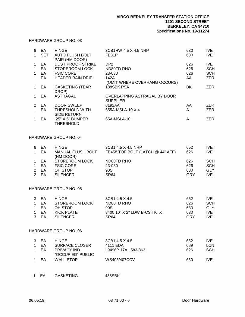
AIRCO BERKELEY TRANSFER STATION OFFICE 1201 SECOND STREET BERKELEY, CA 94710
Specifications No. 19-11274
06.05.19 08 71 00 - 6 Door Hardware
HARDWARE GROUP NO. 03
6 EA HINGE 3CB1HW 4.5 X 4.5 NRP 630 IVE 1 SET AUTO FLUSH BOLT
PAIR (HM DOOR) FB31P 630 IVE
1 EA DUST PROOF STRIKE DP2 626 IVE 1 EA STOREROOM LOCK ND80TD RHO 626 SCH 1 EA FSIC CORE 23-030 626 SCH 1 EA HEADER RAIN DRIP 142A
(OMIT WHERE OVERHANG OCCURS) AA ZER
1 EA GASKETING (TEAR DROP)
188SBK PSA BK ZER
1 EA ASTRAGAL OVERLAPPING ASTRAGAL BY DOOR SUPPLIER
2 EA DOOR SWEEP 8192AA AA ZER 1 EA THRESHOLD WITH
SIDE RETURN 655A-MSLA-10 X 4 A ZER
1 EA .25" X 5" BUMPER THRESHOLD
65A-MSLA-10 A ZER
HARDWARE GROUP NO. 04
6 EA HINGE 3CB1 4.5 X 4.5 NRP 652 IVE 1 EA MANUAL FLUSH BOLT
(HM DOOR) FB458 TOP BOLT (LATCH @ 44" AFF) 626 IVE
1 EA STOREROOM LOCK ND80TD RHO 626 SCH 1 EA FSIC CORE 23-030 626 SCH 2 EA OH STOP 90S 630 GLY 2 EA SILENCER SR64 GRY IVE
HARDWARE GROUP NO. 05
3 EA HINGE 3CB1 4.5 X 4.5 652 IVE 1 EA STOREROOM LOCK ND80TD RHO 626 SCH 1 EA OH STOP 90S 630 GLY 1 EA KICK PLATE 8400 10" X 2" LDW B-CS TKTX 630 IVE 3 EA SILENCER SR64 GRY IVE
HARDWARE GROUP NO. 06
3 EA HINGE 3CB1 4.5 X 4.5 652 IVE 1 EA SURFACE CLOSER 4111 EDA 689 LCN 1 EA PRIVACY IND
"OCCUPIED" PUBLIC L9496P 17A L583-363 626 SCH
1 EA WALL STOP WS406/407CCV 630 IVE
1 EA GASKETING 488SBK
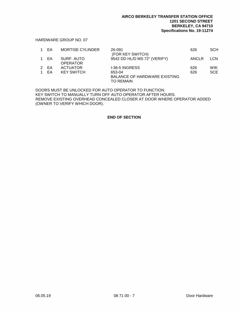
AIRCO BERKELEY TRANSFER STATION OFFICE 1201 SECOND STREET BERKELEY, CA 94710
Specifications No. 19-11274
06.05.19 08 71 00 - 7 Door Hardware
HARDWARE GROUP NO. 07
1 EA MORTISE CYLINDER 26-091 (FOR KEY SWITCH)
626 SCH
1 EA SURF. AUTO OPERATOR
9542 DD HL/D MS 72” (VERIFY) ANCLR LCN
2 EA ACTUATOR I-36-5 INGRESS 626 WIK 1 EA KEY SWITCH 653-04 626 SCE BALANCE OF HARDWARE EXISTING
TO REMAIN
DOORS MUST BE UNLOCKED FOR AUTO OPERATOR TO FUNCTION. KEY SWITCH TO MANUALLY TURN OFF AUTO OPERATOR AFTER HOURS. REMOVE EXISTING OVERHEAD CONCEALED CLOSER AT DOOR WHERE OPERATOR ADDED (OWNER TO VERIFY WHICH DOOR).
END OF SECTION

AIRCO BERKELEY TRANSFER STATION OFFICE 1201 SECOND STREET BERKELEY, CA 94710
Specifications No. 19-11274
06.05.19 08 71 00 - 8 Door Hardware
This Page Intentionally Left Blank
AIRCO BERKELEY TRANSFER STATION OFFICE 1201 SECOND STREET BERKELEY, CA 94710
Specifications No. 19-11274
06.05.19 08 80 00 - 1 Glazing
SECTION 08 80 00
GLAZING PART 1 - GENERAL 1.01 SUMMARY
A. Section Includes 1. Glass and glazing. 2. Window film.
B. Drawings and general provisions of the Contract, including General and Supplementary
Conditions and Division 01 Specification Sections, apply to this Section.
C. Related Section 1. Section 08 14 00 - Wood Doors: Provision of wood doors.
1.02 REFERENCES
A. ANSI - American National Standards Institute 1. Z97.1 - Safety Glazing Materials Used in Buildings - Safety Performance
Specifications and Methods of Test.
B. ASTM - American Society for Testing and Materials 1. C1048 - Standard Specification for Heat-Treated Flat Glass - Kind HS, Kind FT
Coated and Uncoated Glass. 2. C1172 - Standard Specification for Laminated Architectural Flat Glass. 3. E1300 - Standard Practice for Determining Load Resistance of Glass in Buildings. 4. E2010 - Standard Test Method for Positive Pressure Fire Tests of Window Assemblies. 5. E2074 - Standard Test Method for Fire Tests of Door Assemblies, Including Positive
Pressure Testing of Side-Hinged and Pivoted Swinging Door Assemblies.
C. CBC - California Building Code, 2016 Edition
D. CPSC - Consumer Product Safety Commission 1. 16 CFR Part 1201 - Safety Standard for Architectural Glazing Materials.
E. GANA - Glass Association of North America
1. Glazing Manual.
F. UL - Underwriters Laboratories Inc. 1.03 SYSTEM DESCRIPTION
A. Design Requirements 1. Provide glass and glazing that has been produced, fabricated, and installed to
withstand movement without failure including loss or breakage of glass, failure of sealants or gaskets to remain watertight and airtight, deterioration of glass and glazing materials, and other defects in the work.
2. Glass Design: Glass thicknesses indicated on the Drawings are for detailing only. Confirm glass thicknesses by analyzing Project loads and in-service conditions. Provide glass lites for the various size openings in the thicknesses and strengths (annealed or heat-treated) to meet or exceed the following criteria: a. Minimum glass thickness, nominally, of lites in exterior walls is 0.23-inches.
AIRCO BERKELEY TRANSFER STATION OFFICE 1201 SECOND STREET BERKELEY, CA 94710
Specifications No. 19-11274
06.05.19 08 80 00 - 2 Glazing
b. Minimum glass thicknesses of lites, whether composed of annealed or heat-treated glass, are selected so the worst-case probability of failure does not exceed the following: 8 lites per 1000 for lites set vertically or not over 15 degrees off vertical and under wind action. Determine minimum thickness of monolithic annealed glass according to ASTM E1300. For other than monolithic annealed glass, determine thickness per glass manufacturer’s standard method of analysis including applying adjustment factors to ASTM E1300 based on type of glass.
3. Normal thermal movement results from the following maximum change (range) in ambient and surface temperatures acting on glass framing members and glazing components. Base engineering calculation on materials’ actual surface temperatures due to both solar heat gain and nighttime sky heat loss. a. Temperature Change (Range): 120 degrees Fahrenheit ambient; 180 degrees
Fahrenheit material surfaces. 4. Verify locations where safety glazing is required by CBC. Bring to the Architect’s
attention locations not noted as such in the Drawings. Do not proceed until directed by the Architect.
1.04 SUBMITTALS
A. Product Data: Submit manufacturer’s product data for each glass product and glazing material indicated.
B. Samples: Submit samples for verification purposes of 12 inch square samples of each type of
glass indicated except for clear monolithic glass products, and 12 inch long samples of each color required for each type of sealant or gasket exposed to view. Install sealant or gasket sample between 2 strips of material representative in color of the adjoining framing system.
C. Quality Control Submittals
1. Test Reports a. Compatibility and adhesion test reports from sealant manufacturer indicating
that glazing materials were tested for compatibility and adhesion with glazing sealants. Include sealant manufacturer’s interpretation of test results relative to sealant performance and recommendations for primers and substrate preparation needed for adhesion.
b. Product test reports for each type of glazing sealant and gasket indicated, evidencing compliance with requirements specified.
2. Certificates a. Product certificates signed by glazing materials manufacturers certifying that
their products comply with specified requirements. b. Separate certifications are not required for glazing materials bearing
manufacturer’s permanent labels designating type and thickness of glass, provided labels represent a quality control program of a recognized certification agency or independent testing agency acceptable to authorities having jurisdiction.
1.05 QUALITY ASSURANCE
A. Regulatory Requirements 1. Glass and glazing shall meet requirements of CBC Chapter 24. 2. Safety Requirements: Provide glass and glazing complying with ANSI Z97.1 and
CBC Chapter 24 and testing requirements of CPSC 16 CFR Part 1201 for Category II materials.
AIRCO BERKELEY TRANSFER STATION OFFICE 1201 SECOND STREET BERKELEY, CA 94710
Specifications No. 19-11274
06.05.19 08 80 00 - 3 Glazing
3. Fire Resistive Glazing Products: Products identical to those tested in accordance with ASTM E2074 for doors and ASTM E2010 for window assemblies; both labeled and listed by UL.
B. Glazing Publications: Comply with published recommendations of glass product
manufacturers and organizations below, except where more stringent requirements are indicated. Refer to these publications for glazing terms not otherwise defined in this Section or in referenced standards. 1. GANA Publication: “Glazing Manual”.
C. Single-Source Responsibility for Glass: Obtain glass from 1 source for each product
indicated below: 1. Heat-treated glass of each condition indicated, ASTM C1048.
D. Preconstruction Compatibility and Adhesion Testing: Submit to sealant manufacturers,
samples of each glass, gasket, glazing accessory, and glass framing member that will contact or affect glazing sealants for compatibility and adhesion testing as indicated below 1. Use test methods standard with sealant manufacturer to determine if priming and
other specific preparation techniques are required for rapid, optimum glazing sealants adhesion to glass and glazing channel substrates.
2. Submit not less than 9 pieces of each type and finish of glass-framing members and each type, class, kind, condition, and form of glass (monolithic and laminated units) for adhesion testing, as well as one sample of each glazing accessory (gaskets, setting blocks, and spacers) for compatibility testing.
3. Schedule sufficient time to test and analyze results to prevent delay in the Work. 4. Investigate materials failing compatibility or adhesion tests and get sealant
manufacturer’s written recommendations for corrective measures, including using special primers.
5. Testing is not required when glazing sealant manufacturer can submit required preparation data that is acceptable to the Architect and is based on previous testing of current sealant products for adhesion to and compatibility with submitted glazing materials.
1.06 DELIVERY, STORAGE, AND HANDLING
A. Protect glazing materials to comply with manufacturer’s directions and as needed to prevent damage to glass and glazing materials from condensation, temperature changes, direct exposure to sun, or other causes.
1.07 PROJECT CONDITIONS
A. Environmental Conditions: Do not proceed with glazing when ambient and substrate temperature conditions are outside the limits permitted by glazing materials manufacturer or when glazing channel substrates are wet from rain, frost, condensation, or other causes.
1.08 WARRANTY
A. General Warranty: Special warranties specified in this Article shall not deprive the City of other rights the City may have under other provisions of the Contract Documents and shall be in addition to, and run concurrent with, other warranties made by Contractor under requirements of the Contract Documents.

AIRCO BERKELEY TRANSFER STATION OFFICE 1201 SECOND STREET BERKELEY, CA 94710
Specifications No. 19-11274
06.05.19 08 80 00 - 4 Glazing
PART 2 - PRODUCTS 2.01 MANUFACTURERS
A. Acceptable Manufacturers: PPG Industries, Inc.; Guardian SunGuard; Cardinal Industries, or equal.
2.02 MATERIALS
A. Laminated Glass Unit 1. ASTM C1172, safety, 2 ply factory laminated glass, as follows:
a. Outboard Layer: Float glass, ASTM C1048, Kind FT (fully tempered), Type I (transparent glass, flat), Class 1 (clear), Quality q3 (glazing select), 1/8-inch thick, unless otherwise noted.
b. Interlayer: Manufacturer’s standard. c. Inboard Layer: Float glass, ASTM C1048, Kind FT (fully tempered), Type I
(transparent glass, flat), Class 1 (clear), Quality q3 (glazing select), 1/8-inch thick, unless otherwise noted.
2. Laminating Process: Fabricate laminated glass to produce glass free of foreign substances and air or glass pockets. Laminate in autoclave with heat plus pressure.
B. Glazing Accessories: Provide the following as required.
1. Setting Blocks, Spacers and Edge Blocks: Neoprene, EPDM or silicone blocks as required for compatibility with glazing sealants, 80 to 90 Shore A durometer hardness. a. Spacers within air spaces shall be gray in color.
2. Sealant: One part non-acid curing silicone type, as manufactured by Dow Corning Corp., “795”; General Electric Corp., “Silpruf”; Tremco, Inc., “Spectrum 2”, or equal.
3. Glazing Tape: Provide manufacturer’s standard solvent free butyl-polyisobutylene formulation with solids content of 100 percent; in extruded tape form; non-staining and non-migrating in contact with nonporous surfaces; packaged on rolls with release paper on 1 side; with or without continuous spacer rod as recommended by manufacturers of tape and glass for application indicated.
4. Window Film: Provide self-adhered privacy film (matte translucent) as manufactured by 3M, or equal. a. Color: White.
2.03 FABRICATION OF GLASS AND OTHER GLAZING PRODUCTS
A. Fabricate glass and other glazing products in sizes required to glaze openings indicated for the Project, with edge and face clearances, edge and surface conditions, and bite complying with recommendations of product manufacturer and referenced glazing standard as required to comply with system performance requirements.
PART 3 - EXECUTION 3.01 EXAMINATION
A. Examine glass framing, with glazier present, for compliance with the following 1. Manufacturing and installation tolerances, including those for size, squareness, and
offsets at corners. 2. Presence and functioning of weep system. 3. Minimum required face or edge clearances. 4. Effective sealing between joints of glass-framing members.
B. Do not proceed with glazing until unsatisfactory conditions have been corrected.
AIRCO BERKELEY TRANSFER STATION OFFICE 1201 SECOND STREET BERKELEY, CA 94710
Specifications No. 19-11274
06.05.19 08 80 00 - 5 Glazing
3.02 PREPARATION
A. Clean glazing channels and other framing members receiving glass immediately before glazing. Remove coatings that are not firmly bonded to substrates.
3.03 GLAZING, GENERAL
A. Comply with combined recommendations of manufacturers of glass, sealants, gaskets, and other glazing materials, except where more stringent requirements are indicated, including those in referenced glazing publications.
B. Glazing channel dimensions as indicated on Drawings provide necessary bite on glass,
minimum edge and face clearances, and adequate sealant thicknesses, with reasonable tolerances. Adjust as required by Project conditions during installation.
C. Protect glass from edge damage during handling and installation as follows:
1. Use a rolling block in rotating glass units to prevent damage to glass corners. Do not impact glass with metal framing. Use suction cups to shift glass units within openings; do not raise or drift glass with a pry bar. Rotate glass lites with flares or bevels on bottom horizontal edges so edges are located at top of opening, unless otherwise indicated by manufacturer’s label.
2. Remove damaged glass from Project site and legally dispose of off site. Damaged glass is glass with edge damage or other imperfections that, when installed, weaken glass and impair performance and appearance.
D. Apply primers to joint surfaces where required for adhesion of sealants, as determined by
preconstruction sealant-substrate testing.
E. Install elastomeric setting blocks in sill rabbets, sized and located to comply with referenced glazing standard, unless otherwise required by glass manufacturer. Set blocks in thin course of compatible sealant suitable for heel bead.
F. Do not exceed edge pressures stipulated by glass manufacturers for installing glass lites.
G. Provide spacers for glass sizes larger than 50 united inches (length plus height) as follows:
1. Locate spacers inside, outside, and directly opposite each other. Install correct size and spacing to preserve required face clearances, except where gaskets and glazing tapes are used that have demonstrated ability to maintain required face clearances and comply with system performance requirements.
2. Provide 1/8-inch minimum bite of spacers on glass and use thickness equal to sealant width. With glazing tape, use thickness slightly less than final compressed thickness of tape.
H. Provide edge blocking to comply with requirements of referenced glazing publications,
unless otherwise required by glass manufacturer.
I. Set glass lites in each series with uniform pattern, draw, bow, and similar characteristics. 3.04 TAPE GLAZING
A. Position tapes on fixed stops so that when compressed by glass their exposed edges are flush with or protrude slightly above sightline of stops.
B. Install tapes continuously but not in one continuous length. Do not stretch tapes to make
them fit opening.
AIRCO BERKELEY TRANSFER STATION OFFICE 1201 SECOND STREET BERKELEY, CA 94710
Specifications No. 19-11274
06.05.19 08 80 00 - 6 Glazing
C. Where framing joints are vertical, cover these joints by applying tapes to heads and sills first and then to jambs. Where framing joints are horizontal, cover these joints by applying tapes to jambs and then to heads and sills.
D. Place joints in tapes at corners of opening with adjoining lengths butted together, not
lapped. Seal joints in tapes with compatible sealant approved by tape manufacturer.
E. Do not remove release paper from tape until just before each lite is installed.
F. Apply heel bead of elastomeric sealant.
G. Center glass lites in openings on setting blocks and press firmly against tape by inserting dense compression gaskets formed and installed to lock in place against faces of removable stops. Start gasket applications at corners and work toward centers of openings.
H. Apply cap bead of elastomeric sealant over exposed edge of tape.
3.05 GASKET GLAZING (DRY)
A. Fabricate compression gaskets in lengths recommended by gasket manufacturer to fit openings exactly, with stretch allowance during installation.
B. Secure compression gaskets in place with joints located at corners to compress gaskets
producing a weathertight seal without developing bending stresses in glass. Seal gasket joints with sealant recommended by gasket manufacturer.
C. Install gaskets so they protrude past face of glazing stops.
3.06 PROTECTION AND CLEANING
A. Protect exterior glass from breakage immediately after installation by attaching crossed streamers to framing held away from glass. Do not apply markers to glass surface. Remove nonpermanent labels, and clean surfaces.
B. Protect glass from contact with contaminating substances resulting from construction
operations including weld splatter. If, despite such protection, contaminating substances do come into contact with glass, remove them immediately as recommended by glass manufacturer.
C. Examine glass surfaces adjacent to or below exterior concrete and other masonry surfaces
at frequent intervals during construction, but not less than once a month, for build-up of dirt, scum, alkali deposits, or stains, and remove as recommended by glass manufacturer.
D. Remove and replace glass that is broken, chipped, cracked, abraded, or damaged in any
way, including natural causes, accidents, and vandalism, during construction period.
E. Wash glass on both faces in each area of Project not more than 4 days prior to date scheduled for inspections that establish date of Substantial Completion. Wash glass as recommended by glass manufacturer.
END OF SECTION
AIRCO BERKELEY TRANSFER STATION OFFICE 1201 SECOND STREET BERKELEY, CA 94710
Specifications No. 19-11274
06.05.19 09 29 00 - 1 Gypsum Board
SECTION 09 29 00
GYPSUM BOARD PART 1 - GENERAL 1.01 SUMMARY
A. Section Includes 1. Gypsum board screw attached to metal framing and furring members, joint treatment
and accessories. 2. Installation of sound deadening insulation in walls and ceilings and including
acoustical sealant, tape and the like for work of this Section.
B. Drawings and general provisions of the Contract, including General and Supplementary Conditions and Division 01 Specification Sections, apply to this Section.
C. Related Sections
1. Section 06 64 00 - Plastic Paneling: Provision of FRP paneling. 2. Section 07 21 01 - Building Insulation: Provision of acoustical insulation. 3. Section 07 92 00 - Joint Sealants: Provision of caulking and sealants. 4. Section 09 90 00 - Painting and Coating: For finish painting.
1.02 REFERENCES
A. ASTM - American Society for Testing and Materials 1. C475 - Standard Specification for Joint Compound and Joint Tape for Finishing
Gypsum Board. 2. C514 - Standard Specification for Nails for the Application of Gypsum Board. 3. C840 - Standard Specification for Application and Finishing of Gypsum Board. 4. C1002 - Standard Specification for Steel Self-Piercing Tapping Screws for the
Application of Gypsum Panel Products or Metal Plaster Bases to Wood Studs or Steel Studs.
5. C1047 - Standard Specification for Accessories for Gypsum Wallboard and Gypsum Veneer Base.
6. C1396 - Standard Specification for Gypsum Board. 7. E119 - Standard Test Methods for Fire Tests of Building Construction and Materials.
B. CBC - California Building Code, 2016 Edition
C. CFR - Code of Federal Regulations
1. 40 CFR 59 - National Volatile Organic Compound Emission Standards for Consumer and Commercial Products.
D. EPA - Environmental Protection Agency
1. Method 24 - Determination of Volatile Matter Content, Water Content, Density, Volume Solids, and Weight Solids of Surface Coatings.
E. GA - Gypsum Association
1. 201 - Using Gypsum Board for Walls and Ceilings. 2. 214 - Recommended Levels of Gypsum Board Finish. 3. 216 - Application and Finishing of Gypsum Panel Products. 4. 600 - Fire Resistance Design Manual.
AIRCO BERKELEY TRANSFER STATION OFFICE 1201 SECOND STREET BERKELEY, CA 94710
Specifications No. 19-11274
06.05.19 09 29 00 - 2 Gypsum Board
F. UL - Underwriters Laboratories Inc. 1. FRD - Fire Resistance Directory.
1.03 SUBMITTALS
A. Product Data: Submit manufacturer’s product data. Include required fire test results for gypsum board systems on partitions and ceilings.
B. Samples: Manufacturer’s standard size for each textured finish indicated and on same
backing indicated for Work. 1.04 QUALITY ASSURANCE
A. Fire Test Response Characteristics: Where fire resistance rated gypsum board assemblies are indicated, provide gypsum board assemblies that comply with the following requirements: 1. Fire Resistance Ratings: As indicated by GA File Numbers in GA 600 or design
designations in UL FRD or in the listing of another testing and inspecting agency acceptable to authorities having jurisdiction.
2. Gypsum board assemblies indicated are identical to assemblies tested for fire resistance according to ASTM E119 by an independent testing and inspecting agency acceptable to authorities having jurisdiction.
PART 2 - PRODUCTS 2.01 MANUFACTURERS
A. Acceptable Manufacturers: United States Gypsum Co.; Gold Bond Building Products Div., National Gypsum Co.; Pacific Coast Building Products, Pabco Gypsum Division, or equal.
2.02 MATERIALS
A. Gypsum Board 1. Type 1: Fire rated board for fire resistance rated assemblies, ASTM C1396, Type X,
tapered edges, 48 inches wide, 5/8-inch thick. 2. Type 2: Fire rated, mold- and water-resistant board, Type X, tapered edges, 48
inches wide, 5/8-inch thick.
B. Screws: ASTM C1002, machine thread for gypsum board to metal attachments.
C. Nails: ASTM C514, wood thread for metal or gypsum board attachment to wood.
D. Adhesives: Use adhesives that have a VOC content of 50 g/L or less when calculated according to 40 CFR 59, Subpart D (EPA Method 24).
E. Accessories
1. Corner Beads and Casing Beads: ASTM C1047, sheet steel zinc coated by hot-dip process.
2. Reveal Trim: As manufactured by Fry Reglet Corporation, or equal.
F. Joint Treatment Materials: Products of one manufacturer conforming to ASTM C475, ASTM C840, and recommendations of manufacturer of both gypsum board and joint treatment materials for application indicated. Conform to GA 201 and GA 216 for reinforcing tape, joint compound, and water.
AIRCO BERKELEY TRANSFER STATION OFFICE 1201 SECOND STREET BERKELEY, CA 94710
Specifications No. 19-11274
06.05.19 09 29 00 - 3 Gypsum Board
1. Joint Tape a. Cross-laminated, tapered edge, reinforced paper, or fiber glass mesh tape as
recommended by setting type joint compound manufacturer. b. For silicone treated gypsum backer board, use 2 inch wide, 10-inch by 10-inch
woven glass mesh tape. 2. Setting Type Joint Compound: Factory prepackaged, job mixed, chemical hardening
powder products formulated for uses indicated or factory premixed product. Use hot type at exterior gypsum soffits.
G. Acoustical Sealant: As specified in Section 07 92 00.
2.03 FINISHES
A. General: Apply joint treatment at gypsum board joints (both directions), flanges of corner bead, edge trim and control joints, penetrations, fastener heads, surface defects and elsewhere as required to prepare work for decoration. 1. Prefill open joints and rounded or beveled edges, if any, using setting type joint
compound. 2. Apply joint tape at joints between gypsum boards, except where trim accessories are
indicated.
B. Levels of Gypsum Board Finish as Defined by GA 214. Levels are only examples and do not constitute a schedule of finish. See Interior Finish Schedule for levels of finish. 1. Level 0: No taping, finishing, or accessories required. 2. Level 1: All joints and interior angles shall have tape set in joint compound. Surface
shall be free of excess joint compound. Tool marks and ridges are acceptable. a. Provide at ceiling plenum areas and concealed areas.
3. Level 2: All joints and interior angles shall have tape embedded in joint compound and wiped with a joint knife leaving a thin coating of joint compound over all joints and interior angles. Fastener heads and accessories shall be covered with a coat of joint compound. Surface shall be free of excess joint compound. Tool marks and ridges are acceptable. Joint compound applied over the body of the tape at the time of tape embedment shall be considered a separate coat of joint compound and shall satisfy the conditions of this level.
4. Level 3: All joints and interior angles shall have tape embedded in joint compound and one additional coat of joint compound applied over all joints and interior angles. Fastener heads and accessories shall be covered with two separate coats of joint compound. All joint compound shall be smooth and free of tool marks and ridges. Note: It is recommended that the prepared surface be coated with a drywall primer prior to the application of final finishes. a. Provide at back of house and service areas such as mechanical rooms and
janitorial closets. 5. Level 4: All joints and interior angles shall have tape embedded in joint compound
and two separate coats of joint compound applied over all flat joints and one separate coat of joint compound applied over interior angles. Fastener heads and accessories shall be covered with three separate coats of joint compound. All joint compound shall be smooth and free of tool marks and ridges. Note: It is recommended that the prepared surface be coated with a drywall primer prior to the application of final finishes.
6. Level 5: All joints and interior angles shall have tape embedded in joint compound and two separate coats of joint compound applied over all flat joints and one separate coat of joint compound applied over interior angles. Fastener heads and accessories shall be covered with three separate coats of joint compound. A thin skim coat of joint compound trowel applied, or a material manufactured especially for this purpose and applied in accordance with manufacturer’s recommendations, shall be applied to
AIRCO BERKELEY TRANSFER STATION OFFICE 1201 SECOND STREET BERKELEY, CA 94710
Specifications No. 19-11274
06.05.19 09 29 00 - 4 Gypsum Board
the entire surface. The surface shall be smooth and free of tool marks and ridges. Note: It is recommended that the prepared surface be coated with a drywall primer prior to the application of finish paint. a. Provide at panel surfaces where exposed to view; smooth finish. b. Provide at residential corridors and common spaces; smooth finish. c. Provide at residential interior spaces; smooth finish.
C. The finished gypsum board should present a smooth, unblemished, homogenous
appearance with inconspicuous joining between boards and no visible fasteners. There should be no areas of raised fibers on the face paper due to over sanding. Visible fastener pops, seam lines and cracks within the first year will be corrected as required by the guarantee.
PART 3 - EXECUTION 3.01 INSTALLATION
A. Gypsum Board 1. Install and finish gypsum board to comply with ASTM C840 or GA 216.
a. Single Layer: Install in accordance with ASTM C840, except as amended or required by specific fire resistive or sound isolation system detailed. In that instance, application shall conform to requirements of the manufacturer’s tests as reviewed and accepted in the submittal.
b. Double Layer: Conform to applicable portions of ASTM C840, System Classification VIII for installations applied with screws. Conform to required fire resistance standards.
2. Apply in horizontal direction with ends and edges falling on supports. Gypsum board shall be of maximum length possible to reach full wall or ceiling lengths with minimal number of joints.
3. Position boards so that like edges abut, tapered edges against tapered edges and field cut ends against field cut ends. Do not place tapered edges against cut edges or ends. Stagger vertical joints over different studs on opposite sides of partitions.
4. Start installation of panels at exterior wall to position butt joints as far away from exterior wall as possible.
B. Fire Resistant Assemblies: Wherever fire rated gypsum board construction is indicated,
provide materials and installation methods, including types and spacing of fasteners, in accordance with CBC, GA Manual, or listed assembly indicated. Apply firestopping at top of wall and at penetrations through fire resistant assembly in accordance with CBC.
C. Sound Retardant Installations: Provide sound retardant insulation at all changing, toilet, and
shower stall walls. Follow manufacturer’s directions and specifications for conditions of installation. Install from floor surface to bottom side of next floor surface. 1. Wrap with insulation and Lowry Pads and seal electrical or other outlets in sound
isolating partitions. 2. Seal perimeter and penetrations at sound-rated construction to meet specific project
acoustical requirements. 3. Install sealant to completely fill void between gypsum board edges and adjacent
surface.
D. Restrooms, Lavatory Room, and Toilet Rooms: Provide mold- and water-resistant gypsum board.
E. Fastenings: Attach gypsum board to framing with screws, lengths and sizes as
recommended by manufacturer and in accordance with CBC.
AIRCO BERKELEY TRANSFER STATION OFFICE 1201 SECOND STREET BERKELEY, CA 94710
Specifications No. 19-11274
06.05.19 09 29 00 - 5 Gypsum Board
F. Accessories 1. Install corner beads at vertical and horizontal external corners; tape inside corners. 2. Install casing beads whenever edge of gypsum board would otherwise be exposed or
semi-exposed, or where abutting dissimilar materials. 3. After accessories are installed, correct surface damage and defects. 4. Install trims and expansion joints where required.
G. Construction Tolerances
1. Gypsum board surfaces to be painted shall have no measurable variation in any 2 feet-0 inches direction and a maximum variation of 1/8-inch in 10 feet-0 inches when a straightedge is laid on the surface in any direction.
2. Coordinate with tolerances required for surfaces to receive tile. 3. Do not exceed 1/16-inch offset between planes of abutting sheets at edges or ends. 4. Shim panels as necessary to comply with tolerances.
3.02 FINISHING OF GYPSUM BOARD
A. Finish Schedule 1. At Locations Indicated to Receive "Fire-Taping" and at Unexposed Gypsum Board
Applications: Level 1. 2. Areas to Receive Ceramic Tile: Level 3. 3. Locations to Receive Paint with Gloss Level Greater than Eggshell (Except
Restrooms and Utilitarian Areas such as Janitor Closets and Mechanical Rooms): Level 5.
4. All Other Locations: Level 4.
B. Apply joint treatment at gypsum board joints; flanges of corner bead, edge trim and penetrations, fastener heads and surface defects in accordance with ASTM C840 or GA 216. Number of coats of treatment shall be as specified above.
C. Finish Painting: As specified in Section 09 90 00.
END OF SECTION

AIRCO BERKELEY TRANSFER STATION OFFICE 1201 SECOND STREET BERKELEY, CA 94710
Specifications No. 19-11274
06.05.19 09 29 00 - 6 Gypsum Board
This Page Intentionally Left Blank
AIRCO BERKELEY TRANSFER STATION OFFICE 1201 SECOND STREET BERKELEY, CA 94710
Specifications No. 19-11274
06.05.19 09 51 00 - 1 Acoustical Ceilings
SECTION 09 51 00
ACOUSTICAL CEILINGS PART 1 - GENERAL 1.01 SUMMARY
A. Section Includes: Acoustical ceiling panels for patching where required.
B. Drawings and general provisions of the Contract, including General and Supplementary Conditions and Division 01 Specification Sections, apply to this Section.
C. Related Section
1. Section 09 90 00 - Painting and Coating: For finish painting. 1.02 REFERENCES
A. ASTM - American Society for Testing and Materials 1. E84 - Standard Test Method for Surface Burning Characteristics of Building Materials.
B. CBC - California Building Code, 2016 Edition
C. UL - Underwriters Laboratories Inc.
1. FRD - Fire Resistance Directory. 1.03 SUBMITTALS
A. Product Data: Submit manufacturer’s product data completely describing products.
B. Shop Drawings: Show complete ceiling layouts, methods and details of installation, and information required for related work. 1. Indicate where acoustical ceiling panels will be replaced or relocated due to damage
or new work.
C. Samples: 1 panel of each type of acoustical material specified.
D. Quality Control Submittals: Submit manufacturer’s installation instructions. 1.04 QUALITY ASSURANCE
A. Qualifications: Installer shall have completed at least 3 previous projects of similar size and complexity.
B. Regulatory Requirements: Install fire rated ceiling systems in accordance with CBC and UL
FRD listing and requirements of agency having jurisdiction. 1.05 DELIVERY, STORAGE, AND HANDLING
A. Packing and Shipping: Deliver and store packaged products in original containers with seals unbroken and labels intact until time of use.
AIRCO BERKELEY TRANSFER STATION OFFICE 1201 SECOND STREET BERKELEY, CA 94710
Specifications No. 19-11274
06.05.19 09 51 00 - 2 Acoustical Ceilings
B. Storage and Protection 1. Keep materials dry by storing off ground; under watertight covers. 2. Immediately before installation, panels shall be stored for sufficient time to stabilize
temperature and humidity conditions ambient during installation and anticipated for occupancy.
1.06 PROJECT CONDITIONS
A. Environmental Requirements: Do not begin work until residual moisture has dissipated, and comply with the following: 1. Acoustical Ceilings: Maintain uniform temperature of minimum 60 degrees
Fahrenheit and maximum of 90 degrees Fahrenheit and humidity of 20 to 40 percent but no more than 90 percent prior to, during and after installation.
1.07 MAINTENANCE
A. Extra Materials: Provide 5 percent extra quantity of each type of acoustical surface installed. Provide in original unbroken containers plainly marked with type an quantity of contents.
PART 2 - PRODUCTS 2.01 MATERIALS
A. Acoustical Ceiling Panels to Match Existing: Moisture resistant wet formed mineral fiber with factory applied vinyl latex paint and with the following properties: 1. Size: 12 inches by 12 inches by 5/8-inch thick. 2. Edge: Match existing. 3. Surface Burning Characteristics: Class A in accordance with ASTM E84, with flame
spread 25 or under. 4. Color: White. 5. Product: As manufactured by Armstrong World Industries, Inc., “K4C4 Fine
Fissured”, or equal.
B. Fasteners: Screws or nails, as recommended by the acoustical panel manufacturer; concealed to match existing condition.
C. Non-Bridging Paint: As specified in Section 09 90 00.
PART 3 - EXECUTION 3.01 EXAMINATION
A. Salvage existing acoustical ceiling panels that have been removed; clean and verify quantity available for re-use to patch existing ceiling where panels are damaged. Review with the Architect and Owner.
B. Examine areas to receive acoustical treatment and verify that:
1. Installation of building components located in ceiling plenum is complete. 2. Spacing, direction and details of supports to accommodate installation of light
fixtures, diffusers, and other ceiling located items are correct. 3. Areas are clean and free of materials or rubble that could damage acoustical
surfaces.
C. Do not start work until unsatisfactory conditions are corrected.
AIRCO BERKELEY TRANSFER STATION OFFICE 1201 SECOND STREET BERKELEY, CA 94710
Specifications No. 19-11274
06.05.19 09 51 00 - 3 Acoustical Ceilings
3.02 INSTALLATION
A. Acoustical Ceiling Panels: Install in accordance with manufacturer’s written instructions by fastening with screws or nails to ceiling.
B. Remove damaged or soiled material and replace with new and/or salvaged material in good
condition prior to the City’s Project Manager’s acceptance of Project.
C. Prepare acoustical ceiling panels for painting with non-bridging paint specified in Section 09 90 00.
D. Protect acoustical treatment installations from damage during remainder of construction.
END OF SECTION

AIRCO BERKELEY TRANSFER STATION OFFICE 1201 SECOND STREET BERKELEY, CA 94710
Specifications No. 19-11274
06.05.19 09 51 00 - 4 Acoustical Ceilings
This Page Intentionally Left Blank
AIRCO BERKELEY TRANSFER STATION OFFICE 1201 SECOND STREET BERKELEY, CA 94710
Specifications No. 19-11274
06.05.19 09 65 00 - 1 Resilient Flooring
SECTION 09 65 00
RESILIENT FLOORING PART 1 - GENERAL 1.01 SUMMARY
A. Section Includes 1. Sheet vinyl. 2. Resilient wall base.
B. Drawings and general provisions of the Contract, including General and Supplementary
Conditions and Division 01 Specification Sections, apply to this Section.
C. Related Sections 1. Section 09 68 13 - Tile Carpeting: Provision of carpet tile. 2. Section 09 97 25 - Vapor Emission Treatment Systems: Provision of vapor emission
treatment. 1.02 REFERENCES
A. ASTM - American Society for Testing and Materials 1. F710 - Standard Practice for Preparing Concrete Floors to Receive Resilient Flooring. 2. F1861 - Standard Specification for Resilient Wall Base. 3. F1869 - Standard Test Method for Measuring Moisture Vapor Emission Rate of
Concrete Subfloor Using Anhydrous Calcium Chloride. 4. F1913 - Standard Specification for Vinyl Sheet Floor Covering Without Backing.
B. CALGreen - California Green Building Standards, 2016 Edition
1.03 SYSTEM DESCRIPTION
A. Performance Requirements: Adhesives used on the Project shall comply with CALGreen Code Nonresidential Mandatory Measures, Chapter 5, Division 5.5, Section 5.504, Article 5.504.4.1.
1.04 SUBMITTALS
A. Product Data: Submit manufacturer’s product data for each type of product specified.
B. Samples: Submit samples for initial selection purposes in form of manufacturer’s color charts consisting of actual sections of resilient flooring and wall bases showing full range of colors and patterns available for each different product indicated.
1.05 MAINTENANCE
A. Extra Materials: Furnish 100 linear feet in roll form of each different composition, wearing surface, color, and pattern of sheet vinyl and resilient wall base installed.
AIRCO BERKELEY TRANSFER STATION OFFICE 1201 SECOND STREET BERKELEY, CA 94710
Specifications No. 19-11274
06.05.19 09 65 00 - 2 Resilient Flooring
PART 2 - PRODUCTS 2.01 MANUFACTURERS
A. Acceptable Manufacturers 1. Sheet Vinyl: Armstrong Flooring, “ColorArt® Accolade Plus™, or equal. 2. Resilient Wall Base: Johnsonite, or equal.
2.02 MATERIALS
A. Sheet Vinyl: Unbacked, non-layered homogeneous construction with true through-pattern wear layer and commercial UV-cured polyurethane coating, complies with ASTM F1913. 1. Overall Thickness: 0.080-inch. 2. Surface Wear Layer: 0.080-inch. 3. Width: 6 feet. 4. Color and Pattern: As selected by the Architect from manufacturer’s full range of
available colors. 5. Provide integral cove base at toilet rooms.
B. Resilient Wall Base: Products complying with ASTM F1861.
1. Style: Cove with top-set toe. 2. Minimum Nominal Thickness: 1/8-inch. 3. Height: 6 inches. 4. Lengths: Coils in lengths standard with manufacturer but not less than 100 feet. 5. Interior and Exterior Corners and Ends: Field-formed. 6. Color and Pattern: As selected by the Architect from manufacturer’s full range of
available colors. 7. Provide wall base at locations other than toilet rooms.
2.03 INSTALLATION ACCESSORIES
A. Concrete Slab Primer: Nonstaining type as recommended by flooring manufacturer.
B. Trowelable Underlayments and Patching Compounds: Latex modified, portland cement based formulation provided or approved by resilient flooring manufacturer for applications indicated.
C. Rod for Heat-Welding Seams: Product of floor covering manufacturer in color to match
field color of resilient floor covering.
D. Adhesives: Waterproof, nonflammable, type as recommended by resilient flooring manufacturer. 1. Adhesives shall be compatible with vapor emission treatment systems specified in
Section 09 97 25. PART 3 - EXECUTION 3.01 EXAMINATION
A. Examine substrates, areas, and conditions for compliance with requirements for maximum moisture content, alkalinity range, installation tolerances, and other conditions affecting resilient flooring performance. Verify that substrates and conditions are satisfactory for resilient flooring installation and comply with requirements specified.
AIRCO BERKELEY TRANSFER STATION OFFICE 1201 SECOND STREET BERKELEY, CA 94710
Specifications No. 19-11274
06.05.19 09 65 00 - 3 Resilient Flooring
B. Concrete Subfloors: Verify that concrete slabs comply with ASTM F710 and the following: 1. Slab substrates are dry and free of curing compounds, sealers, hardeners, and other
materials that may interfere with adhesive bond. Determine adhesion and dryness characteristics by performing bond and moisture tests recommended by the resilient flooring manufacturer.
2. Subfloors are free of cracks, ridges, depressions, scale, and foreign deposits. 3. Concrete shall be allowed to cure for 90 to 120 days and must be properly sealed.
Test concrete for vapor emission by the Calcium Chloride Moisture test method in compliance with ASTM F1869. Emission rate shall not exceed 3 lb/24 hr/1000 sq. ft. Treat with vapor emission treatment systems specified in Section 09 97 25, as required.
3.02 INSTALLATION
A. General: Comply with manufacturers’ installation directions and other requirements indicated that are applicable to each type of installation included in Project.
B. Sheet Flooring Installation
1. Unroll floor covering and allow to stabilize before cutting and fitting. 2. Layout floor covering to comply with the following requirements:
a. Terminate joints at centerline of doorways where adjacent flooring is dissimilar. b. The Architect will approve all seaming patterns. c. Maintain uniformity of sheet floor covering direction. d. Arrange for minimum number of seams and place them in inconspicuous and
low-traffic areas and not less than 6 inches away from parallel joints in flooring substrates.
e. Match edges of floor coverings for color shading and pattern at seams according to manufacturer’s written recommendations.
f. Avoid cross seams. g. Scribe, cut and fit floor coverings to butt neatly and tightly to vertical surfaces
and permanent fixtures, including cabinets, pipes, outlets, edgings, door frames and thresholds.
3. Adhere floor covering to substrates to comply with floor covering manufacturer’s written instructions, including those for trowel notching, adhesive mixing and adhesive open and working times.
4. Heat Welded Seams: Rout joints and heat wield with welding bead, permanently fusing sections into a seamless floor covering. Prepare, weld, and finish seams according to manufacturer’s written instructions and ASTM F1516 to produce surfaces flush with adjoining floor covering surfaces.
5. Integral Flash Cove Base Where Indicated: Cove sheet floor coverings up vertical surfaces to form integral base of 6 inches minimum over cove support strip with top edge butted against and covered by cap molding. Wrap cove around inside and outside corners, and heat weld at a 45 degree angle.
6. Hand roll floor covering in both directions from center out to embed floor coverings in adhesive and eliminate trapped air. At walls, door casings, and other locations where access by roller is impractical, press floor coverings firmly in place with flat-bladed instrument.
C. Resilient Wall Base Installation
1. Apply resilient wall base to walls, casework and other permanent fixtures in rooms and areas where base is required. Install wall base in lengths as long as practicable. Tightly adhere wall base to substrate throughout length of each piece, with base in continuous contact with horizontal and vertical substrates.
AIRCO BERKELEY TRANSFER STATION OFFICE 1201 SECOND STREET BERKELEY, CA 94710
Specifications No. 19-11274
06.05.19 09 65 00 - 4 Resilient Flooring
2. Place resilient accessories so they are butted to adjacent materials of type indicated and bond to substrates with adhesive. Install reducer strips at edges of flooring that otherwise would be exposed.
3.03 CLEANING AND PROTECTION
A. Perform the following operations immediately after completing installation: 1. Remove visible adhesive and other surface blemishes using cleaner recommended
by manufacturers. 2. Sweep or vacuum floor thoroughly. 3. Do not wash floor until after time period recommended by manufacturer. 4. Damp-mop resilient flooring to remove black marks and soil.
B. Protect flooring against mars, marks, indentations, and other damage from construction
operations and placement of equipment and fixtures during remainder of construction period. Use protection methods indicated or recommended by flooring manufacturer.
END OF SECTION
AIRCO BERKELEY TRANSFER STATION OFFICE 1201 SECOND STREET BERKELEY, CA 94710
Specifications No. 19-11274
06.05.19 09 68 13 - 1 Tile Carpeting
SECTION 09 68 13
TILE CARPETING PART 1 - GENERAL 1.01 SUMMARY
A. Section Includes: Carpet tile and accessories.
B. Drawings and general provisions of the Contract, including General and Supplementary Conditions and Division 01 Specification Sections, apply to this Section.
C. Related Sections
1. Section 09 65 00 - Resilient Flooring: Provision of resilient wall base. 2. Section 09 97 25 - Vapor Emission Treatment Systems: Provision of vapor emission
treatment. 1.02 REFERENCES
A. AATCC - American Association of Textile Chemists and Colorists 1. 16.3 - Colorfastness to Light: Xenon-Arc 2. 134 - Electrostatic Propensity of Carpets. 3. 175 - Stain Resistance: Pile Floor Coverings.
B. ASTM - American Society for Testing and Materials
1. E648 - Standard Test Method for Critical Radiant Flux of Floor-Covering Systems Using a Radiant Heat Energy Source.
2. F710 - Standard Practice for Preparing Concrete Floors to Receive Resilient Flooring.
3. F1869 - Standard Test Method for Measuring Moisture Vapor Emission Rate of Concrete Subfloor Using Anhydrous Calcium Chloride.
4. F2170 - Standard Test Method for Determining Relative Humidity in Concrete Floor Slabs Using in situ Probes.
C. BAAQMD - Bay Area Air Quality Management District
1. Regulation 8 - Organic Compounds, Rule 51 - Adhesive and Sealant Products.
D. CALGreen - California Green Building Standards, 2016 Edition
E. City of Berkeley 1. EPP - Environmentally Preferable Purchasing Policy.
F. CRI - Carpet and Rug Institute
1. 104 - Standard for Installation of Commercial Carpet. 2. Green Label Plus Testing Program. 3. TARR - Texture Appearance Retention Rating
G. DGS - California Department of General Services
1. California Gold Sustainable Carpet Standard.
H. DOC - Department of Commerce 1. FF 1-70 - Methenamine Pill Test.
AIRCO BERKELEY TRANSFER STATION OFFICE 1201 SECOND STREET BERKELEY, CA 94710
Specifications No. 19-11274
06.05.19 09 68 13 - 2 Tile Carpeting
I. Green Seal, Inc. 1. GS-36 - Adhesives for Commercial Use.
J. ISO - International Organization for Standardization
K. NFPA - National Fire Protection Association
1. 258 - Research Test Method for Determining Smoke Generation of Solid Materials.
L. NSF/ANSI - NSF International/American National Standards Institute 1. 140 - Sustainability Assessment for Carpet.
M. SCAQMD - South Coast Air Quality Management District
1. Rule 1168 - Adhesive Applications, October, 2003 Amendment. 1.03 SYSTEM DESCRIPTION
A. Performance Requirements 1. Technical
a. Durability: TARR Rating; 3.5. b. Fiber: Solution dyed, 6 or 6,6 nylon; modification ratio (MR) less than 2.5. c. Static Control: AATCC 134; Less than 3.5 kV. d. Colorfastness and Fading: Xenon Arc, AATCC 16.3; Not less than 4 at 60
AFU’s. e. Stain Resistance: ASTCC 175; Greater than 8. f. Pile Density Range: 5,400 to 6,285. g. Gauge: 1/12 and 5/64 are acceptable. h. Stitches per Inch: 8.66 to 11.5. i. Flammability
1) DOC FF-1-70: Pass. 2) NFPA 258 (Smoke Density): 450 or less. 3) ASTM E648 (Floor Radiant Panel Test): 0.45 W/cm2 or higher.
2. Sustainability and Environmental Requirements a. Comply with testing and product requirements of CRI’s “Green Label Plus”
program. b. Comply with the City of Berkeley Environmentally Preferable Purchasing Policy
(EPP). c. Manufacturer shall have an established reclamation and recycling program for
the supplied carpet at the end of its useful life. d. Sustainability: NSF/ANSI 140; Gold rating. e. Environmental Management: ISO 14001 manufacturing facility. f. Carpet tile shall comply with the California Gold Sustainable Carpet Standard. g. All materials in the carpet tile shall be 100 percent non-PVC. h. Recycled Content
1) Total by Weight: 35 percent, minimum. 2) Post-Consumer by Weight: 10 percent, minimum.
i. Adhesives and Sealants 1) Meets SCAQMD Rule 1168. 2) Meet or exceed the requirements of the BAAQMD Regulation 8, Rule 51. 3. Aerosol adhesives shall meet the VOC limits of GS-36.
B. Regulatory Requirement: Carpet used on the Project shall comply with CALGreen Code
Nonresidential Mandatory Measures, Chapter 5, Division 5.5, Section 5.504, Articles 5.504.4.4., 5.504.4.4.1, and 5.504.4.4.2.
AIRCO BERKELEY TRANSFER STATION OFFICE 1201 SECOND STREET BERKELEY, CA 94710
Specifications No. 19-11274
06.05.19 09 68 13 - 3 Tile Carpeting
1.04 SUBMITTALS
A. Product Data 1. Manufacturer’s data for carpet tile describing design and performance requirements,
sizes, and method of installation. 2. Product information for each type of installation accessory required. 3. Submit book for color/pattern selection by User Group. Each User Group may select
up to 4 colors for review.
B. Samples 1. Tile: Full size carpet tile of each type and color required. 2. Submit 4 tiles of each color/pattern for each User Group, up to 4 selected colors for
confirmation of pattern, color variation, and selected size. 3. Edge Striping: 9 inches long for each type.
C. Substitution Requests: Identify product to be considered; show compliance with
requirements for substitutions and the following, as applicable: 1. Detailed comparison of significant qualities of proposed substitution with those
specified. Significant qualities will include attributes such as performance, weight, size, durability, visual effect, sustainable design characteristics, warranties, and specific features and requirements indicated.
2. Product data. 3. Samples. 4. Certificates and qualification data. 5. Cost information, including a proposal of change, if any, in the Contract Sum. 6. Contractor's certification that proposed substitution complies with requirements in this
specification Section, except as indicated in substitution request.
D. Informational Submittals: Statement of installer qualifications.
E. Closeout Submittals 1. Extended warranties. 2. Maintenance instructions.
1.05 QUALITY ASSURANCE
A. Installer Qualifications: Firm specializing in carpet installation, with documented successful experience in installation of carpeting similar to that required for this Project.
B. Odor: Materials used in construction of carpet tiles shall not give off any odors which could
be unpleasant or hazardous to building occupants, and shall meet all VOC limit requirements. This shall include offgassing and chemical migration in backing materials.
C. Mockups: First installed area or example of each type of tile carpeting or accessory shall
serve as a mockup for review by the Architect and the City of workmanship and interface with adjacent construction and floor finishes.
1.06 COORDINATION
A. Sequence reinstallation of carpet with other work to minimize possibility of damage and soiling during remainder of construction period.
AIRCO BERKELEY TRANSFER STATION OFFICE 1201 SECOND STREET BERKELEY, CA 94710
Specifications No. 19-11274
06.05.19 09 68 13 - 4 Tile Carpeting
1.07 DELIVERY, STORAGE, AND HANDLING
A. Store carpet tiles at least 3 days prior to installation in area of installation to achieve temperature stability in accordance with CRI 104 Standard. 1. Temperature of concrete slab substrate shall not be less than 65 degrees Fahrenheit. 2. Maintain these conditions at least 48 hours prior to installation and 72 hours after
completion.
B. Do not stack carpet tile the equivalent of more than six cartons high to avoid potential crushing.
1.08 MAINTENANCE
A. Submit manufacturer's printed instructions for maintenance of carpet tile including recommended methods and cleaning frequencies for maintaining optimum conditions of materials under anticipated traffic and exposures. Include precautions against materials and methods detrimental to carpet performance or to topical coating or to latex used between backings.
B. Attic Stock: After completion of work, deliver 1 full carton, of each carpet tile type, color,
and pattern installed. 1. Furnish accessory components as required. 2. Furnish from same production run as materials installed. 3. Package replacement materials in full carton of approximately 20 tiles, clearly
identified by appropriate labels including dye lot number. 1.09 WARRANTY
A. Contractor: Provide the City with a 2-year written warranty, co-executed by the installing subcontractor, agreeing to repair, replace, or reset carpet tile that fails in installation materials or workmanship within the warranty period.
B. Manufacturer: Provide the City with carpet manufacturer’s 15-year standard, non-prorated
warranty covering face wear, moisture barrier, soil and stain protection, wick-back, delamination, tuft bind, unraveling, and static protection.
PART 2 - PRODUCTS 2.01 MATERIALS
A. Carpet Tile, General 1. Face yarns shall be of same dye batch, and finish material shall be of one mill run. 2. Consistency shall be such that any tile shall be interchangeable with any other tile,
within a dye lot, with no visual difference. 3. Carpet shall have a built-in, permanent antimicrobial treatment for protection against
bacteria and fungus growth. 4. Carton Labeling: Mark each carpet tile carton according to style, color, pattern, and
dye lot.
B. Carpet Tile 1. Size: 18 inches by 36 inches. 2. Installation: Vertical ashlar pattern. 3. Construction: Textured patterned loop. 4. Fiber: “Econyl.” 5. Dye Method: 100 percent solution dyed.
AIRCO BERKELEY TRANSFER STATION OFFICE 1201 SECOND STREET BERKELEY, CA 94710
Specifications No. 19-11274
06.05.19 09 68 13 - 5 Tile Carpeting
6. Face Weight: 18 ounces per square yard. 7. Gauge: 5/64. 8. Pile Thickness: 0.102-inch. 9. Stitches per Inch: 9.9. 10. Pattern Match: Not required. 11. Primary Backing: Non-woven synthetic fiber. 12. Style: To be selected from the Divergent Collection. 13. Color: As selected by the Architect and Owner. 14. Product: As manufactured by Mannington Commercial, “Divergent Collection”, or
equal. a. Includes Current, Flow, and Ebb patterns.
C. Carpet Tile, Walk-off Mat
1. Size: 24 inches by 24 inches. 2. Construction: Multi-level loop. 3. Yarn System: Ecosolution q nylon. 4. Dye Method: 100 percent solution dyed. 5. Protective Treatment: SSP Shaw soil protection. 6. Tufted Yarn Weight: 28 oz/yd2. 7. Machine Gauge: 1/12-inch. 8. Pile Thickness: 0.129-inch. 9. Stitches: 9/inch. 10. Pattern: Portal Tile. 11. Color: As selected by the Architect and Owner. 12. Product: As manufactured by Shaw Contract, “Portal Tile from the All Access
Collection”, or equal.
D. Miscellaneous Materials 1. Adhesives: Release type, waterproof, with no adverse effects on indoor air quality;
as recommended by carpet tile manufacturer and meeting the VOC requirements. a. Adhesives shall be compatible with vapor emission treatment systems
specified in Section 09 97 25. 2. Sub-Floor Filler/Underlayment: Latex cementitious paste for filling, leveling, and
ramping; acceptable to manufacturer of carpet material furnished; as manufactured by ARDEX Americas, "SD-P Instantpatch”, or equal.
3. Self-Leveling Underlayment Over Concrete: As manufactured by ARDEX Americas, "K-15”, or equal.
4. Fast-Setting Underlayment Over Plywood: As manufactured by ARDEX Americas, "K-55”, or equal.
5. Metal Carpet Edge Protection: Extruded anodized aluminum; height and profile as required and selected for installation; as manufactured by Schlüter Systems; Pemko Manufacturing Company Inc., or equal.
6. Self-Adhesive Protective Covering: As manufactured by Poly-Tak Proteciton Systems Inc., "Poly-Tak”, or equal.
7. Other Materials: As recommended by carpet manufacturer and as selected by installer to meet Project circumstances and requirements.
PART 3 - EXECUTION 3.01 EXAMINATION
A. Verify that substrates are dry, free of dust and harmful substances, and in satisfactory condition to receive carpeting materials.
AIRCO BERKELEY TRANSFER STATION OFFICE 1201 SECOND STREET BERKELEY, CA 94710
Specifications No. 19-11274
06.05.19 09 68 13 - 6 Tile Carpeting
B. Substrate Testing 1. Perform test on new concrete topping to verify substrate compliance requirements of
carpet manufacturer requirements. Moisture Vapor Emission Rate (MVER) content test shall be in accordance with ASTM F1869, relative humidity tests in accordance with ASTM F2170, and alkalinity tests in accordance with ASTM F710. a. Where calcium chloride test results are satisfactory but there is reason to
suspect that unacceptable moisture levels below the upper 2 centimeters of the concrete may still exist, a relative humidity probe shall be used to test the full depth of the slab.
2. Perform bond tests to ascertain presence of substances detrimental to obtaining adhesive bond.
C. Where tests are not satisfactory, notify Contract Administrator for review of conditions and
to determine a resolution acceptable to the Contract Administrator. 1. Treat with vapor emission treatment systems specified in Section 09 97 25, as
required. 3.02 PREPARATION
A. General: Comply with CRI 104, Section 6.2, “Site Conditions; Floor Preparation”, and carpet tile manufacturer’s written recommendations and installation instructions to ensure that each substrate is properly prepared to receive carpet tile installation.
B. Clear away debris and scrape up cementitious deposits from concrete surfaces to receive
carpet tile.
C. Remove coatings, curing compounds, and other substances from flooring substrates that are incompatible with carpet tile adhesives and that contain soap, wax, oil, or silicone. Completely remove previous adhesives prior to application of new carpet tile adhesives. Do not use solvents for removing substances. Use mechanical methods recommended in writing by the carpet tile manufacturer.
D. Use subfloor filler to fill cracks, gaps, and depressions and for leveling to required
tolerance.
E. Seal powdery or porous surfaces with sealer recommended by carpet tile manufacturer.
F. Broom and vacuum clean substrates to be covered immediately before installing carpet tile. After cleaning, examine substrates for moisture, alkaline salts, carbonation, or dust. Proceed with installation only after unsatisfactory conditions have been corrected.
G. Unwrap carpet tiles in a well ventilated location prior to installation. Air the carpet tiles out
in off-site location such as a ventilated warehouse for at least 2 days prior to installation. 3.03 INSTALLATION
A. General 1. Apply in accordance with manufacturer's instructions for tile and backing, and
requirements of CRI 104. 2. Integrate and blend carpet tiles from different cartons to ensure minimal variation in
color match. 3. Cut carpet tile clean. Fit carpet tight to intersection with vertical surfaces without
gaps.
B. Layout: As recommended by manufacturer for each carpet tile and layout pattern selected.
AIRCO BERKELEY TRANSFER STATION OFFICE 1201 SECOND STREET BERKELEY, CA 94710
Specifications No. 19-11274
06.05.19 09 68 13 - 7 Tile Carpeting
C. Apply floor adhesive in accordance with manufacturer’s instructions.
D. Join tiles snugly together. Continually check that tiles are being placed together with correct firmness.
E. When placing tiles, brush face pile back from edge and tip tile into place to prevent pile
yarns from becoming entrapped in joint.
F. After installation, carpet tiles within a continuous carpet area exhibiting an unacceptable difference in appearance due to color or light reflectance variation attributed to the manufacturing process shall be selectively relocated or replaced.
3.04 FIELD QUALITY CONTROL
A. Manufacturer's agent shall supervise installation to a point at which he feels that installer is performing satisfactorily.
B. Snugness Testing
1. Measure distance along 10 installed tiles. There should be a 1/4-inch gain in distance along 10 installed tiles.
2. If gain is less than 1/4-inch, peaking of tiles can occur. A wide gap between tiles may occur if gain is more than 1/4-inch.
3.05 CLEANING
A. Remove and dispose of trimmings, excess pieces of carpet, and laying materials from each area as it is completed.
B. Vacuum carpet using commercial machine with face-beater element unless otherwise
recommended by carpet manufacturer.
C. Remove spots. Replace carpet tiles where spots cannot be removed. Do not get solvent used for cleaning into carpet backing system.
D. Use sharp scissors to remove protruding face yarn.
3.06 PROTECTION
A. Do not allow construction traffic, other than as may be required to fit up specific carpeted area, to traverse completed work.
B. Provide specified covering as necessary to protect carpet from damage from traffic and
subsequent construction operations.
C. Use plywood or hardboard covering, if heavy items are to be moved across carpet tile.
END OF SECTION

AIRCO BERKELEY TRANSFER STATION OFFICE 1201 SECOND STREET BERKELEY, CA 94710
Specifications No. 19-11274
06.05.19 09 68 13 - 8 Tile Carpeting
This Page Intentionally Left Blank
AIRCO BERKELEY TRANSFER STATION OFFICE 1201 SECOND STREET BERKELEY, CA 94710
Specifications No. 19-11274
06.05.19 09 90 00 - 1 Painting and Coating
SECTION 09 90 00
PAINTING AND COATING PART 1 - GENERAL 1.01 SUMMARY
A. Section Includes: Surface preparation, painting, and finishing of all new and existing exposed interior items and surfaces, except prefinished items and unless otherwise indicated.
B. Drawings and general provisions of the Contract, including General and Supplementary
Conditions and Division 01 Specification Sections, apply to this Section.
C. Related Sections 1. Section 06 10 00 - Rough Carpentry: For finish painting of rough carpentry. 2. Section 08 11 15 - Steel Doors and Frames: For finish painting of steel doors and
frames. 3. Section 08 14 00 - Wood Doors: For finish painting of wood doors. 4. Section 08 71 00 - Door Hardware: For requirements for protection of finish hardware
during painting. 5. Section 09 29 00 - Gypsum Board: For finish painting of gypsum board. 6. Section 09 51 00 - Acoustical Ceilings: For finish painting of acoustical ceiling panels.
1.02 REFERENCES
A. ASTM - American Society for Testing and Materials 1. D16 - Standard Terminology for Paint, Related Coatings, Materials, and Applications.
B. BMC - Berkeley Municipal Code
1. Resolution No. 62,259-N.S. - Environmentally Preferable Purchasing Policy (EPP).
C. CALGreen - California Green Building Standards, 2016 Edition
D. CFR - Code of Federal Regulations 1. 40 CFR 59 - National Volatile Organic Compound Emission Standards for Consumer
and Commercial Products.
E. EPA - Environmental Protection Agency
F. FM - Factory Mutual
G. SSPC - The Society for Protective Coatings 1. SP 10 - Surface Preparation Specification No. 10: Near-White Blast Cleaning.
H. UL - Underwriters Laboratories Inc.
1.03 DEFINITIONS
A. “Paint”: As used herein, means coating systems materials including primers, emulsions, epoxy, enamels, sealers, fillers, and other applied materials whether used as prime, intermediate or finish coats.
AIRCO BERKELEY TRANSFER STATION OFFICE 1201 SECOND STREET BERKELEY, CA 94710
Specifications No. 19-11274
06.05.19 09 90 00 - 2 Painting and Coating
B. Standard coating terms defined in ASTM D16 apply to this Section. 1. “Flat”: Refers to a lusterless or matte finish with a gloss range below 15 when
measured at an 85-degree meter. 2. “Eggshell”: Refers to low-sheen finish with a gloss range between 20 and 35 when
measured at a 60-degree meter. 3. “Semigloss”: Refers to medium-sheen finish with a gloss range between 35 and 70
when measured at a 60-degree meter. 4. “Full Gloss”: Refers to high-sheen finish with a gloss range more than 70 when
measured at a 60-degree meter. 1.04 SYSTEM DESCRIPTION
A. Performance Requirements 1. This Section shall comply with the purchasing policy requirements of BMC Resolution
No. 62,259-N.S. 2. Paint exposed surfaces whether or not colors are designated in the schedules, except
where a surface or material is specifically indicated not to be painted or is to remain natural. Where an item or surface is not specifically mentioned, paint the same as similar adjacent materials or surfaces. If color or finish is not designated, the Architect will select from standard colors or finishes available.
3. Painting is not required on prefinished items, finished metal surfaces, concealed surfaces, operating parts and labels.
4. Do not paint over UL, FM, or other code required labels or equipment name, identification, performance rating or nomenclature plates.
B. Paints and coatings used on the Project shall comply with CALGreen Code Nonresidential
Mandatory Measures, Chapter 5, Division 5.5, Section 5.504, Article 5.504.4.3. 1.05 SUBMITTALS
A. Product Data: Submit manufacturer’s product data for each paint system specified, including block fillers and primers. 1. Provide manufacturer’s technical information including label analysis and instructions
for handling, storage and application of each material proposed for use. 2. List each material and cross reference the specific coating, finish system and application.
Identify each material by the manufacturer’s catalog number and general classification.
B. Samples 1. Following the selection of colors and glosses by the Architect, submit samples for the
Architect’s review. a. Provide 1 sample of each color and each gloss for each material on which the
finish is specified to be applied. b. Except as otherwise directed by the Architect, make samples approximately 8
inches by 10 inches in size. c. Provide field mockups for each final paint color and texture approval in the form
of actual application of the materials on actual surfaces to be painted for approval by the Architect. Areas shall be 4 feet by 4 feet.
d. Allow for 1 additional mockup of each color. 2. In addition, revise and resubmit each sample or field mockup as requested until the
required gloss, color and texture are achieved. Such samples or field mockups, when approved, will become standards of color and finish for accepting or rejecting the work of this Section.
3. Do not commence finish painting until approved samples are on file at the job site.
AIRCO BERKELEY TRANSFER STATION OFFICE 1201 SECOND STREET BERKELEY, CA 94710
Specifications No. 19-11274
06.05.19 09 90 00 - 3 Painting and Coating
C. Quality Control Submittals: Provide certification by the manufacturer that products supplied comply with local regulations controlling use of volatile organic compounds (VOCs).
1.06 QUALITY ASSURANCE
A. Provide primers and undercoat paint produced by the same manufacturer as finish coats. 1. Review other Sections of these Specifications as required, verifying the prime coats to be
used and assuring compatibility of the total coating system for the various substrates. 2. Upon request, furnish information on the characteristics of the specific finish materials
to assure that compatible prime coats are used. 3. Provide barrier coats over non-compatible primers, or remove the primer and re-prime
as required. 4. Notify the Architect in writing of anticipated problems in using the specified coating
systems over prime coatings supplied under other Sections.
B. Applicator Qualifications: Use adequate numbers of skilled workmen who are thoroughly trained and experienced in the necessary crafts and who are completely familiar with the specified requirements and the methods needed for proper performance of the work of this Section.
C. Mockups: Apply samples of each paint system indicated and each color and finish selected
to verify preliminary selections made under sample submittals and to demonstrate aesthetic effects and set quality standards for materials and execution.
1.07 DELIVERY, STORAGE, AND HANDLING
A. Acceptance at Site: Deliver materials to the job site in manufacturer’s original, unopened packages and containers bearing manufacturer’s name and label and the following information: 1. Product name or title of material. 2. Product description (generic classification or binder type). 3. Manufacturer’s stock number and date of manufacture. 4. Contents by volume for pigment and vehicle constituents. 5. Thinning instructions. 6. Application instructions. 7. Color name and number.
B. Storage and Protection
1. Store materials not in use in tightly covered containers in well ventilated area at minimum ambient temperature of 45 degrees Fahrenheit. Maintain containers used in storage in clean condition, free of foreign materials and residue.
2. Protect from freezing. Take necessary measures to ensure that workers and work areas are protected from fire and health hazards resulting from handling, mixing, and application.
1.08 PROJECT CONDITIONS
A. Environmental Requirements 1. Apply water based paints only when the temperature of surfaces to be painted and
surrounding air temperatures are between 50 and 90 degrees Fahrenheit, unless otherwise permitted by the manufacturers’ printed instructions as approved by the Architect.
2. Do not apply solvent-thinned paints when the temperature of surfaces to be painted and the surrounding air temperatures are below 45 degrees Fahrenheit, unless otherwise permitted by the manufacturers’ printed instructions as approved by the Architect.
AIRCO BERKELEY TRANSFER STATION OFFICE 1201 SECOND STREET BERKELEY, CA 94710
Specifications No. 19-11274
06.05.19 09 90 00 - 4 Painting and Coating
3. Do not apply paint in rain, fog, or mist; or when the relative humidity exceeds 85 percent. Do not apply paint to damp or wet surfaces, unless otherwise permitted by the manufacturers’ printed instructions as approved by the Architect.
4. Applications may be continued during inclement weather only within the temperature limits specified by the paint manufacturer as being suitable for use during application and drying periods.
1.09 MAINTENANCE
A. Upon completion of the work of this Section, deliver to the City’s Project Manager an extra stock of 5 gallons of each color, type, and gloss of interior paint used in the Work, tightly sealing each container, and clearly labeling with contents and location where used.
PART 2 - PRODUCTS 2.01 MANUFACTURERS
A. Acceptable Manufacturers: Benjamin Moore; DuraSeal, or equal. 2.02 PAINT MATERIALS
A. General 1. Paint Materials, General: Provide block fillers, primers, finish coat materials, and
related materials that are compatible with one another and the substrates indicated under conditions of service and application, as demonstrated by the manufacturer, based on testing and field experience.
2. Material Quality: Provide manufacturer’s best quality trade sale paint material of the various coating types specified. Paint material containers not displaying manufacturer’s product identification will not be acceptable.
3. Chemical Components of Field-Applied Paints and Coatings: Provide products that comply with the following limits for VOC content, exclusive of colorants added to a tint base, when calculated according to 40 CFR 59, Subpart D (EPA Method 24) and the following chemical restrictions; these requirements do not apply to primers or finishes that are applied in a fabrication or finishing shop: a. VOC Content of Interior Paints and Coatings: Not more than 5 g/L. b. Aromatic Compounds: Paints and coatings shall not contain more than 1.0
percent by weight of total aromatic compounds (hydrocarbon compounds containing one or more benzene rings).
c. Restricted Components: Paints and coatings shall not contain any of the following: 1) Acrolein. 2) Acrylonitrile. 3) Antimony. 4) Benzene. 5) Butyl benzyl phthalate. 6) Cadmium. 7) Di (2-ethylhexyl) phthalate. 8) Di-n-butyl phthalate. 9) Di-n-octyl phthalate. 10) 1,2-dichlorobenzene. 11) Diethyl phthalate. 12) Dimethyl phthalate. 13) Ethylbenzene. 14) Formaldehyde. 15) Hexavalent chromium.
AIRCO BERKELEY TRANSFER STATION OFFICE 1201 SECOND STREET BERKELEY, CA 94710
Specifications No. 19-11274
06.05.19 09 90 00 - 5 Painting and Coating
16) Isophorone. 17) Lead. 18) Mercury. 19) Methyl ethyl ketone. 20) Methyl isobutyl ketone. 21) Methylene chloride. 22) Naphthalene. 23) Toluene (methylbenzene). 24) 1,1,1-trichloroethane. 25) Vinyl chloride.
4. Colors: As selected by the Architect from manufacturer’s full range. 2.03 APPLICATION EQUIPMENT
A. For application of the approved paint, use only such equipment as is recommended for application of the particular paint by the manufacturer of the particular paint, and as approved by the Architect.
B. Prior to use of application equipment, verify that the proposed equipment is actually
compatible with the material to be applied, and that integrity of the finish will not be jeopardized by use of the proposed equipment.
2.04 OTHER MATERIALS
A. Provide other materials not specifically described but required for a complete and proper installation, as selected by the Contractor subject to the approval of the Architect.
PART 3 - EXECUTION 3.01 PREPARATION
A. General: Mix and prepare paint materials in strict accordance with the manufacturers’ recommendations as approved by the Architect.
B. Surface Preparation
1. General a. Perform preparation and cleaning procedures in strict accordance with the paint
manufacturers’ recommendations as approved by the Architect. b. Remove removable items which are in place and are not scheduled to receive
paint finish; or provide surface applied protection prior to surface preparation and painting operations.
c. Following completion of painting in each space or area, reinstall the removed items by using workmen who are skilled in the necessary trades.
2. At existing surfaces, remove unwanted items, patch all holes, sand irregularities, and clean and prime patches prior to painting.
3. Schedule the cleaning and painting so that dust and other contaminants from the cleaning process will not fall onto wet newly painted surfaces.
C. Preparation of Wood Surfaces
1. Clean wood surfaces until free from dirt, oil, and other foreign substance. 2. Smooth finished wood surfaces exposed to view, using the proper sandpaper. Where
so required, use varying degrees of coarseness in sandpaper to produce a uniformly smooth and unmarred wood surface. a. Lightly sand existing wood to even out surfaces.
AIRCO BERKELEY TRANSFER STATION OFFICE 1201 SECOND STREET BERKELEY, CA 94710
Specifications No. 19-11274
06.05.19 09 90 00 - 6 Painting and Coating
3. Unless specifically approved by the Architect, do not proceed with painting of wood surfaces until the moisture content of the wood is 12 percent or less as measured by a moisture meter approved by the Architect.
D. Preparation of Metal Surfaces
1. Thoroughly clean surfaces until free from dirt, oil and grease. 2. Allow to dry thoroughly before application of paint. 3. Aluminum Substrates: Remove surface oxidation.
3.02 PAINT APPLICATION
A. General 1. Touch-up shop-applied prime coats which have been damaged, and touch-up bare
areas prior to start of finish coats application. 2. Slightly vary the color of succeeding coats. 3. Sand and dust between coats to remove defects visible to the unaided eye from a
distance of 5 feet. 4. On removable panels and hinged panels, paint the back sides to match the exposed
sides. 5. When patch painting, paint to nearest breakpoint or entire plane if whole room; refer
to Finish Schedule.
B. Drying: Allow sufficient drying time between coats, modifying the period as recommended by the material manufacturer to suite adverse weather conditions.
C. Brush Applications
1. Brush out and work the brush coats onto the surface in an even film. 2. Cloudiness, spotting, holidays, laps, brush marks, runs, sags, ropiness and other
surface imperfections will not be acceptable.
D. Spray Application 1. Confine spray application to metal framework and similar surfaces where hand brush
work would be inferior. 2. Where spray application is used, apply each coat to provide the hiding equivalent of
brush coats. 3. Do not double back with spray equipment to build up film thickness of 2 coats in 1
pass.
E. Miscellaneous Surfaces and Procedures 1. Exposed Mechanical Items
a. Provide powder coat finish at electric panels. b. Finish access doors, conduits, pipes, ducts, grilles, registers, vents and items
of similar nature to match the adjacent wall and ceiling surfaces, or as directed. c. Paint visible duct surfaces behind vents, registers, and grilles flat black. d. Wash metal with solvent, prime and apply 2 coats of alkyd enamel.
2. Exposed Pipe and Duct Insulation a. Apply 1 coat of latex paint on insulation which has been sized or primed under
other Sections; apply 2 coats on such surfaces when unprepared. b. Match color of adjacent surfaces. c. Remove band before painting, and replace after painting.
3. Hardware a. Paint prime coated hardware to match adjacent surfaces; b. Paint metal portions of head seals, jamb seals, and astragal seals to match the
color of the door frame unless otherwise directed by the Architect.
AIRCO BERKELEY TRANSFER STATION OFFICE 1201 SECOND STREET BERKELEY, CA 94710
Specifications No. 19-11274
06.05.19 09 90 00 - 7 Painting and Coating
4. Wet Areas a. For oil base paints, use 1 percent phencimercuric or 4 percent
tetrachlorophenol. b. For water emulsion and glue size surfaces, use 4 percent sodium
tetrachlorophenate. 5. Interior: Use “stipple” finish where enamel is specified. 6. Exposed Vents: Apply 2 coats of heat resistant paint approved by the Architect.
3.03 INTERIOR PAINT SCHEDULE
A. Gypsum Board 1. Eggshell Finish (Used Everywhere Except Toilet Rooms Unless Otherwise Noted):
Minimum 2 finish coats to cover over a primer. a. Primer: Latex based, interior primer applied at spreading rate required to
achieve a total dry film thickness as recommended by the manufacturer. b. Finish Coats: Low luster eggshell, acrylic-latex based, interior enamel applied
at spreading rate required to achieve a total dry film thickness as recommended by the manufacturer.
2. Semigloss Finish (Toilet Rooms): Minimum 2 finish coats to cover over a primer. a. Primer: Latex based, interior primer applied at spreading rate required to
achieve a total dry film thickness as recommended by the manufacturer. b. Finish Coats: Semigloss, acrylic latex, interior enamel applied at spreading rate
required to achieve a total dry film thickness as recommended by the manufacturer.
B. Wood Intended for Opaque Finish 1. Semigloss Finish: Finish coat(s) to cover over a primer.
a. Primer: Latex based, interior primer applied at spreading rate required to achieve a total dry film thickness as recommended by the manufacturer.
b. Finish Coat: Semigloss, acrylic latex, interior enamel applied at spreading rate required to achieve a total dry film thickness as recommended by the manufacturer.
C. Wood Intended for Transparent Finish and For Existing Wood Touchup and Repair
1. Waterborne, Satin-Varnish Finish: 2 finish coats of a waterborne, clear-satin varnish over a filler coat and a waterborne, interior wood stain. Wipe wood filler before applying stain. a. Filler Coat: Paste-wood filler applied at spreading rate recommended by the
manufacturer. b. Stain Coat: Waterborne, interior wipe-on wood stain applied at spreading rate
recommended by the manufacturer. c. First and Second Finish Coats: Waterborne, wipe-on polyurethane finish
applied at spreading rate recommended by the manufacturer.
D. Ferrous and Galvanized Metal 1. Semigloss, Acrylic Enamel Finish: 1 finish coat over enamel undercoat and a primer.
Primer is not required on shop-primed items. a. Primer: Quick drying, rust-inhibitive epoxy metal primer, as recommended by
the manufacturer for this substrate, applied at spreading rate required to achieve a total dry film thickness as recommended by the manufacturer.
b. Undercoat: Acrylic, interior enamel undercoat or semigloss, acrylic latex, interior enamel, as recommended by the manufacturer for this substrate, applied at spreading rate required to achieve a total dry film thickness as recommended by the manufacturer.
c. Finish Coat: Semigloss, acrylic latex, interior enamel applied at spreading rate required to achieve a total dry film thickness as recommended by the manufacturer.
AIRCO BERKELEY TRANSFER STATION OFFICE 1201 SECOND STREET BERKELEY, CA 94710
Specifications No. 19-11274
06.05.19 09 90 00 - 8 Painting and Coating
E. Non-Bridging Paint at Acoustical Ceiling Panels: Apply in accordance with manufacturer’s recommendations, as manufactured by ProCoat Products, Inc., “ProCoustic”, or equal.
END OF SECTION
AIRCO BERKELEY TRANSFER STATION OFFICE 1201 SECOND STREET BERKELEY, CA 94710
Specifications No. 19-11274
06.05.19 09 97 25 - 1 Vapor Emission Treatment Systems
SECTION 09 97 25
VAPOR EMISSION TREATMENT SYSTEMS PART 1 - GENERAL 1.01 SUMMARY
A. Section Includes: Vapor control barrier applied to existing concrete slabs at interior areas scheduled to receive moisture sensitive floor coverings.
B. Drawings and general provisions of the Contract, including General and Supplementary
Conditions and Division 01 Specification Sections, apply to this Section.
C. Related Sections 1. Section 09 65 00 - Resilient Flooring: Provision of resilient flooring. 2. Section 09 68 13 - Tile Carpeting: Provision of carpet tile.
1.02 REFERENCES
A. ASTM - American Society for Testing Materials. 1. C156 - Standard Test Method for Water Retention by Concrete Curing Materials. 2. C309 - Standard Specification for Liquid Membrane-Forming Compounds for Curing
Concrete. 3. C1315 - Standard Specification for Liquid Membrane-Forming Compounds Having
Special Properties for Curing and Sealing Concrete. 4. D1308 - Standard Test Method for Effect of Household Chemicals on Clear and
Pigmented Organic Finishes. 5. D4541 - Standard Test Method for Pull-Off Strength of Coatings Using Portable
Adhesion Testers. 1.03 SUBMITTALS
A. Product Data: Provide the following: 1. Descriptive Literature: Materials and accessories. 2. Project References: Similar project completed within 5 years. 3. Installer: Direct factory/manufacturer employed personnel certificates for each installer. 4. Field Documents: Manufacturer shall provide written acceptance of on-site conditions
and surface applied contaminates, prior to barrier installations. No exceptions.
B. Quality Assurance Submittals: Provide the following independent test results indicating compliance 1. ASTM C309 Curing Requirements. 2. ASTM D1308 Alkali Resistance. 3. ASTM C1315 Curing/Sealing Requirements. 4. ASTM C156 Water Retention Level. 5. ASTM D4541 Floor Adhesion Testing.
1.04 QUALITY ASSURANCE
A. Qualifications 1. Manufacturer: Manufacturing history of 10 years and product liability insurance in the
amount of $1,000,000 per occurrence. 2. Installer: Manufacturer-approved personnel. No exceptions.
AIRCO BERKELEY TRANSFER STATION OFFICE 1201 SECOND STREET BERKELEY, CA 94710
Specifications No. 19-11274
06.05.19 09 97 25 - 2 Vapor Emission Treatment Systems
1.05 WARRANTY
A. Manufacturer’s Warranty: Written warranty, signed by manufacturer, agreeing to replace water system that does not comply with requirements or that does not remain watertight during specified warranty period.
B. Warranty shall not exclude surface contaminates or resin and silicate surface treatments.
Installations on slab surfaces deems acceptance of on-site conditions. Manufacturer is responsible for written acceptance prior to installation.
C. Workmanship and Materials Warranty
1. Manufacturing Defects Warranty Period: 10 years. 2. Installation Defects Warranty: 10 years. 3. Warranty Covering Improper Installations: 10 years. 4. Moisture and Alkalinity Damage to Flooring: 10 years. 5. Manufacturer’s limited warranty shall cover 100 percent of the cost to repair or
replace floor coverings damaged by moisture and alkalinity. Coverage shall include: a. Installed epoxy based vapor/alkalinity barrier. b. Floor covering systems or resinous materials. c. Adhesives, patching materials and installation accessories. d. All installation labor charges involved.
PART 2 - PRODUCTS 2.01 MANUFACTURERS
A. Acceptable Manufacturers: Floor Seal Technology, Inc., “MES-100”; Synthetics International, “Synthetic 30”, or equal.
2.02 MATERIALS
A. At Existing Concrete: Provide low emission, resin penetrant applied to slab surfaces with vapor emission and alkalinity levels caused by residual water-of-convenience and interstitial condensation of moisture from building atmosphere.
B. Materials containing water based solutions of sodium, potassium, and lithium silicates do
not meet performance levels specified in this Section. Silicate based solutions are chemically reactive and do not meet the intent of ASTM C309. See ASTM documents for verification.
PART 3 - EXECUTION 3.01 EXAMINATION AND PREPARATION
A. Manufacturer shall accept existing conditions in writing prior to installation.
B. General: Coordinate work with work specified under other sections to ensure proper and adequate interface of work. Protect all adjacent surfaces from drips, spray, air pollution of surrounding environment, and other damage from work.
3.02 APPLICATION
A. At Existing Concrete 1. Shot blast concrete surface to open pore and grind near edges. Remove bond
breakers; remove curing compounds, and ensure a clean surface profile.
AIRCO BERKELEY TRANSFER STATION OFFICE 1201 SECOND STREET BERKELEY, CA 94710
Specifications No. 19-11274
06.05.19 09 97 25 - 3 Vapor Emission Treatment Systems
2. All structural cracks, control joins and cold joints shall be cleaned for treatment application. Broom sweep and vacuum out debris. Any features with large, thorough passage into soil substrate shall be thoroughly dug out, vacuumed, filled with appropriate crack filling material.
3. All cleaned structural cracks and control joints shall be treated per system requirements for a warranted system. a. Fill all structural cracks, control joints and cold joints, and clean and fill all
divots, voids, chips or other surface feature irregularities with an approved resin/ 100 percent portland based type compound. Gypsum based filling materials will fail under moisture conditions and are not allowed under any circumstances.
4. The acceptable concrete surface profile will feature a texture that is similar to a 200 grit sandpaper. Slick surfaces from curing compounds and/or release agents must be shot blasted completely off.
3.03 FIELD QUALITY CONTROL
A. Validation Testing: Perform post installation testing at 1 calcium chloride test per 1,000 square feet. Interior temperature and humidity to be similar during the City’s occupancy.
B. Reapply materials in areas above flooring manufacturer’s limits, prior to floor covering
installations at no additional charge to the City. 3.04 PROTECTION
A. Protection: Protect installations during specified cure periods from any kind of traffic, topical water, and contaminants.
END OF SECTION
AIRCO BERKELEY TRANSFER STATION OFFICE 1201 SECOND STREET BERKELEY, CA 94710
Specifications No. 19-11274
06.05.19 09 97 25 - 4 Vapor Emission Treatment Systems
This Page Intentionally Left Blank
AIRCO BERKELEY TRANSFER STATION OFFICE 1201 SECOND STREET BERKELEY, CA 94710
Specifications No. 19-11274
06.05.19 10 14 00 - 1 Signage
SECTION 10 14 00
SIGNAGE PART 1 - GENERAL 1.01 SUMMARY
A. Section Includes: Code-related and wayfinding signage.
B. Drawings and general provisions of the Contract, including General and Supplementary Conditions and Division 01 Specification Sections, apply to this Section.
1.02 REFERENCES
A. ADA - Americans with Disabilities Act
B. ASTM - American Society for Testing and Materials 1. A1008 - Standard Specification for Steel, Sheet, Cold-Rolled, Carbon, Structural,
High-Strength Low-Alloy, High-Strength Low-Alloy with Improved Formability, Solution Hardened, and Bake Hardenable.
C. CBC - California Building Code, 2016 Edition
1.03 SYSTEM DESCRIPTION
A. Design Requirements: Design all signs as required by ADA and CBC - Title 24. 1.04 QUALITY ASSURANCE
A. Regulatory Requirements 1. Comply with ADA and CBC requirements for signage, to include Braille. 2. Provide signs at public toilet rooms with the following text: MEN, WOMEN.
1.05 SUBMITTALS
A. Product Data: Submit manufacturer’s product data describing materials and signs.
B. Shop Drawings 1. Provide shop drawings showing construction details for approval before proceeding
with fabrication. Include full size details of exposed edges, joints between materials, hanging, hinging and locking systems and any other details which would affect sign appearance.
2. Fasteners: Detail methods of fastenings and provide exact specifications for all fasteners noted on shop drawings.
3. Artwork a. Submit full size patterns or prints of typical copy layouts and/or graphic
elements to be applied on signs. Using layouts on the Drawings as a guide, optically enlarge and hand correct images before submitting to the Architect for approval before fabrication.
b. Elevator Lobby fire evacuation map art shall be schematically presented. Submit camera ready artwork for all floors to the Architect for approval prior to fabrication.
AIRCO BERKELEY TRANSFER STATION OFFICE 1201 SECOND STREET BERKELEY, CA 94710
Specifications No. 19-11274
06.05.19 10 14 00 - 2 Signage
4. Sign Location: Provide Graphic Schedule and location plans to identify and locate all signs. Item numbers listed in the Graphic Schedule shall be found on location plans and shall identify locations of specific sign items.
C. Samples
1. On 6-inch by 6-inch pieces of actual sign materials, submit to the Architect for review and approval, 3 samples of painted and graphic finishes, in each material, color and finish, with texture to simulate actual conditions.
2. Provide listing of the material and application for each coat of each finish sample. 3. Be prepared to resubmit each sample as requested until required sheen, color and
texture are approved. 4. Acrylic: Submit color and finish samples of plastics for approval before proceeding
with fabrication. No substitution in color, thickness, finish or plastics will be accepted without written approval of the Architect.
5. Fasteners: Submit 1 sample of all fasteners and hardware for approval. 6. Paint: Submit 3 color and finish samples of all paints and finishes for approval prior to
fabrication.
D. Operation and Maintenance: Provide the City’s Project Manager with proper cleaning instructions required for continued maintenance of signs.
1.06 QUALITY ASSURANCE
A. Pre-Installation Conferences: Sign locations shown on the location plans are for general information only. Prior to installation and as required, arrange meetings with the Architect at the site for final location for all sign items.
PART 2 - PRODUCTS 2.01 MANUFACTURERS
A. Acceptable Manufacturers: ASI Sign Systems, Inc.; Superior Sign Systems; Vomar Products, Inc., or equal.
2.02 MATERIALS
A. Exterior Accessibility Signs: 18 gauge steel, stretcher leveled, ASTM A1008, Class I, matte finish, galvanized; screen printed blue with white symbol in accordance with ADA.
B. Plastic Signs: Matte finish acrylic plastic, minimum 1/8-inch thick, without frame, with
corners radiused. Message and background color shall be sub-surface printed. Provide with raised room numbers and Braille.
C. Mounting Tape: Double-sided vinyl foam tape; provide silicone adhesive for attachment to
wall surface.
D. Fasteners: Where fasteners are indicated or required, use exposed “torx type” tamper-proof security screws.
E. Coatings for Acrylic Plastic Sheet: Use colored coatings, including inks and paints for copy
and background colors, that are recommended by acrylic manufacturers for optimum adherence to acrylic surface and are non-fading for the application intended.
AIRCO BERKELEY TRANSFER STATION OFFICE 1201 SECOND STREET BERKELEY, CA 94710
Specifications No. 19-11274
06.05.19 10 14 00 - 3 Signage
2.03 ACRYLIC SIGNS
A. Acrylic Signs: Comply with requirements indicated for materials, thicknesses, finishes, colors, designs, shapes, sizes, and details of construction.
B. Unframed Acrylic Signs: Fabricate signs with edges mechanically and smoothly finished to
conform with the following requirements: 1. Edge Condition: Square cut. 2. Corner Condition: 1/2-inch radius. 3. Produce smooth, even, level sign panel surfaces, constructed to remain flat under
installed conditions within a tolerance of plus or minus 1/16-inch measured diagonally.
C. Graphic Content and Style: Provide sign copy that complies with the requirements indicated for size, style, spacing, content, position, material, finishes, and colors of letters, numbers, and other graphic devices.
D. Message Inserts: Where sign type makes provision for changeable name slots, provide
laser printed name strips with text as scheduled. Obtain message from the City’s Project Manager before fabrication. Where no text is scheduled, insert blank message strip in slot for future text by the City’s Project Manager.
E. Photopolymer (Raised Copy): Machine-cut copy characters from matte finish opaque
acrylic sheet and chemically weld onto the acrylic sheet forming sign panel face. Produce precisely formed characters with square cut edges free from burrs and cut marks. 1. Panel Material: Matte-finished acrylic stock with opaque color coating surface
applied; 2 colors, minimum 70 percent contrast between color 1 and color 2. 2. Raised Copy Thickness: Not less than 1/32-inch.
2.04 FINISHES
A. Colors: For exposed sign material that requires applied colors and other characteristics related to appearance, see Drawings.
2.05 BRAILLE SYMBOLS
A. Braille Symbols: California Contracted Grade 2 Braille shall be used wherever Braille symbols are specifically required in other portions of these standards. Dots shall be 1/10-inch on centers in each cell with 2/10-inch space between cells. Dots shall be raised a minimum of 1/40-inch above the background.
PART 3 - EXECUTION 3.01 EXAMINATION
A. Examine the substrate and conditions in which the work is to be installed. Correct all unsatisfactory substrate and conditions prior to start of installation.
3.02 INSTALLATION
A. General 1. Install signage in neat and proper manner. 2. Install sign items, including all components, in accordance with reviewed Graphic
Schedule at locations shown. 3. Install signs properly aligned, level and true to line and dimension.
AIRCO BERKELEY TRANSFER STATION OFFICE 1201 SECOND STREET BERKELEY, CA 94710
Specifications No. 19-11274
06.05.19 10 14 00 - 4 Signage
B. Install with reviewed manufacturer’s adhesive or mechanical fasteners after application of finish painting at heights noted.
3.03 SCHEDULE
A. Signage font, size, color and background color as indicated on the Drawings.
B. Signage shall be in compliance with CBC.
END OF SECTION
AIRCO BERKELEY TRANSFER STATION OFFICE 1201 SECOND STREET BERKELEY, CA 94710
Specifications No. 19-11274
06.05.19 10 28 13 - 1 Toilet Accessories
SECTION 10 28 13
TOILET ACCESSORIES PART 1 - GENERAL 1.01 SUMMARY
A. Section Includes: Toilet accessories, including backing plates for grab bars.
B. Drawings and general provisions of the Contract, including General and Supplementary Conditions and Division 01 Specification Sections, apply to this Section.
1.02 REFERENCES
A. ADA - Americans with Disabilities Act
B. AISI - American Iron and Steel Institute
C. ASTM - American Society for Testing and Materials 1. A153 - Standard Specification for Zinc Coating (Hot-Dip) on Iron and Steel Hardware. 2. A653 - Standard Specification for Steel Sheet, Zinc-Coated (Galvanized) or Zinc-Iron
Alloy-Coated (Galvannealed) by the Hot-Dip Process. 3. B456 - Standard Specification for Electrodeposited Coatings of Copper Plus Nickel
Plus Chromium and Nickel Plus Chromium. 4. C1503 - Standard Specification for Silvered Flat Glass Mirror. 5. F446 - Standard Consumer Safety Specification for Grab Bars and Accessories
Installed in the Bathing Area.
D. CBC - California Building Code, 2016 Edition 1.03 SUBMITTALS
A. Product Data: Submit manufacturer’s product data for each toilet accessory item specified, including construction details relative to materials, dimensions, gauges, profiles, mounting method, specified options, and finishes.
B. Shop Drawings: Submit setting drawings where cutouts are required in other work,
including templates, substrate preparation instructions, and directions for preparing cutouts and installing anchorage devices.
C. Contract Closeout Submittals: Submit maintenance instructions including replaceable parts
and service recommendations. 1.04 QUALITY ASSURANCE
A. Regulatory Requirements 1. Grab Bars and Fasteners: Strength of grab bars, fasteners and mounting devices
shall comply with CBC and ADA requirements. 2. Grab Bar Surfaces: Conform to CBC. 3. Mounting Heights of Accessories: Comply with requirements of CBC. 4. Operating Pressure for Soap Dispensers: Comply with ADA.
B. Inserts and Anchorages: Furnish accessory manufacturers’ standard concealed inserts and
anchoring devices. Coordinate delivery with other work to avoid delay.
AIRCO BERKELEY TRANSFER STATION OFFICE 1201 SECOND STREET BERKELEY, CA 94710
Specifications No. 19-11274
06.05.19 10 28 13 - 2 Toilet Accessories
1.05 PROJECT CONDITIONS
A. Coordination: Coordinate accessory locations, installation, and sequencing with other work to avoid interference with and ensure proper installation, operation, adjustment, cleaning, and servicing of toilet accessory items.
1.06 WARRANTY
A. Warranty: Submit a written warranty executed by mirror manufacturer, agreeing to replace any mirrors that develop visible silver spoilage defects within warranty period.
B. Warranty Period: 10 years from date of Substantial Completion.
C. Warranty shall not deprive the City of other rights the City may have under other provisions
of the Contract Documents and will be in addition to and run concurrent with other warranties made by the Contractor under requirements of the Contract Documents.
PART 2 - PRODUCTS 2.01 MANUFACTURERS
A. Acceptable Manufacturers: Bobrick Washroom Equipment, Inc.; Bradley Corporation, or equal.
2.02 MATERIALS
A. General: Fabricate toilet accessory items form the following materials and according to requirements specified for individual accessory items. 1. Stainless Steel: AISI Type 302/304, with polished No. 4 finish, 22 gauge minimum
thickness, unless otherwise indicated. 2. Galvanized Steel Sheet: ASTM A653, G60. 3. Chromium Plating: Nickel and chromium electro-deposited on base metal, ASTM
B456, Type SC 2. 4. Galvanized Steel Mounting Devices: ASTM A153, hot-dip galvanized after
fabrication. 5. Fasteners: Screws, bolts, and other devices of same material as accessory unit, or of
galvanized steel where concealed. 6. Keys: Provide universal keys for access to toilet accessory units requiring internal
access for servicing, resupply. Provide a minimum of 6 keys to the City’s Project Manager.
7. Mirrors: ASTM C1503, Mirror Glazing Quality, clear-glass mirrors, nominal 6.0 mm thick.
2.03 ACCESSORIES
A. Toilet Accessories 1. Grab Bars: Surface-mounted, 1-1/4 inches diameter, 18 inches, 36 inches, and 42
inches where indicated, 18 gauge stainless steel, satin finish, as manufactured by Bobrick Washroom Equipment, Inc., “B-5806 Series”, or equal.
2. Seat Cover Dispenser: Surface-mounted, 22 gauge stainless steel, satin finish, as manufactured by Bobrick Washroom Equipment, Inc., “ClassicSeries B-221”, or equal.
3. Toilet Tissue Dispenser: Surface-mounted, multi-roll, satin finish stainless steel unit with stainless steel dispensing mechanism, as manufactured by Bobrick Washroom Equipment, Inc., “ClassicSeries B-2888”, or equal.
AIRCO BERKELEY TRANSFER STATION OFFICE 1201 SECOND STREET BERKELEY, CA 94710
Specifications No. 19-11274
06.05.19 10 28 13 - 3 Toilet Accessories
4. Mirror: Surface-mounted, glass mirror with stainless steel channel frame, bright polished finish, 18 inches by 30 inches, as manufactured by Bobrick Washroom Equipment, Inc., “B-165 Series”, or equal.
5. Soap Dispenser: Surface-mounted, 20 gauge stainless steel, satin finish, for antibacterial soaps, as manufactured by Bobrick Washroom Equipment, Inc., “ConturaSeries 818615”, or equal.
6. Paper Towel Dispenser and Waste Receptacle: Semi-recess-mounted, 18 gauge stainless steel, satin finish, as manufactured by Bobrick Washroom Equipment, Inc., “TrimLineSeries B-38032”, or equal.
B. Mounting Plates: Non-corrosive material. Provide as required.
2.04 FABRICATION
A. General: Only a maximum 1-1/2 inch diameter, unobtrusive stamped manufacturer logo, as approved by the Architect, is permitted on exposed face of toilet or bath accessory units. On either interior surface not exposed to view or back surface, provide additional identification by either a printed, waterproof label or a stamped nameplate, indicating manufacturer’s name and product model number.
B. Surface-Mounted Toilet Accessories, General: Except where otherwise indicated, fabricate
units with tight seams and joints, exposed edges rolled. Hang doors or access panels with continuous stainless steel piano hinge. Provide concealed anchorage wherever possible.
PART 3 - EXECUTION 3.01 INSTALLATION
A. Install toilet accessory units according to manufacturer’s instructions, using fasteners appropriate to substrate as recommended by unit manufacturer. Install units plumb and level, firmly anchored in locations and at heights indicated.
B. Secure mirrors to walls in concealed, tamperproof manner with special hangers, toggle
bolts, or screws. Set units plumb, level, and square at locations indicated, according to manufacturer’s instructions for type of substrate involved.
C. Install grab bars to withstand a downward load of at least 250 lbf, complying with ASTM
F446.
D. Provide accessories as indicated on the Drawings. 3.02 ADJUSTING AND CLEANING
A. Adjust toilet accessories for proper operation and verify that mechanisms function smoothly. Replace damaged or defective items.
B. Clean and polish all exposed surfaces strictly according to manufacturer’s
recommendations after removing temporary labels and protective coatings.
END OF SECTION

AIRCO BERKELEY TRANSFER STATION OFFICE 1201 SECOND STREET BERKELEY, CA 94710
Specifications No. 19-11274
06.05.19 10 28 13 - 4 Toilet Accessories
This Page Intentionally Left Blank
AIRCO BERKELEY TRANSFER STATION OFFICE 1201 SECOND STREET BERKELEY, CA 94710
Specifications No. 19-11274
06.05.19 22 00 00 - 1 Plumbing Requirements
SECTION 22 00 00
PLUMBING REQUIREMENTS
PART 1 - GENERAL
1.1 SUMMARY
A. Work Included: Work included in 22 00 00 applies to Division 22 work to provide materials, labor, tools, permits and incidentals to make plumbing systems ready for Owner's use for proposed project.
B. Related Work Specified Elsewhere:
1. Contents of Section applies to Division 22 specifications.
2. Requirements of Section are a minimum for Division 22 Sections, unless otherwise stated in each Section, in which case that Section's requirements take precedence.
1.2 DEFINITIONS
A. Following is a list of abbreviations generally used in Division 22:
1. ADA Americans with Disabilities Act
2. AHJ Authority Having Jurisdiction
3. ANSI American National Standards Institute
4. ARI Air-Conditioning & Refrigeration Institute
5. ASHRAE American Society of Heating, Refrigerating and Air-Conditioning Engineers
6. ASME American Society of Mechanical Engineers
7. ASTM American Society for Testing and Materials
8. ASSE American Society of Sanitary Engineering
9. UMC Uniform Mechanical Code
10. UPC Uniform Plumbing Code
11. CISPI Cast Iron Soil Pipe Institute
12. FM FM Global
13. HI Hydraulic Institute Standards
14. HVAC Heating, Ventilating and Air Conditioning
15. MSS Manufacturers Standardization Society
16. NEC National Electric Code
17. NFPA National Fire Protection Association
18. NSF National Sanitation Foundation.
19. OSHA Occupational Safety and Health Administration
20. SMACNA Sheet Metal and Air Conditioning Contractors' National Association, Inc.
21. UL Underwriters Laboratories Inc.
B. Provide: To furnish and install, complete and ready for the intended use.
AIRCO BERKELEY TRANSFER STATION OFFICE 1201 SECOND STREET BERKELEY, CA 94710
Specifications No. 19-11274
06.05.19 22 00 00 - 2 Plumbing Requirements
C. Furnish: Supply and deliver to the project site, ready for unpacking, assembly and installation.
D. Install: Includes unloading, unpacking, assembling, erecting, installation, applying, finishing, protecting, cleaning and similar operations at the project site as required to complete items of work furnished by others.
1.3 ADDITIONAL REQUIREMENTS TO DIVISION 01
A. Record Drawings:
1. Show changes and deviations from the Drawings. Include issued Addendum and change order items.
2. Make changes to the Drawings in a neat, clean, and legible manner.
B. Product Data:
1. Submit manufacturer's technical data, installation instructions and dimensioned drawings for products, fixtures, equipment and devices installed, supplied or provided. Refer to individual specification sections for specific items required in product data submittal. Submit at one time in 3-ring binder, tabbed and referenced to match the Contract Documents.
2. Maintain an updated product submittal package to be included in the final operation and maintenance e documentation.
1.4 QUALITY ASSURANCE
A. Where Contract Documents are at variance with applicable codes governing work, code and local jurisdiction requirements take precedence, and include cost necessary for code compliance or local jurisdiction compliance in bid price. Machinery and equipment to comply with Occupational Safety and Health Act of 1970, as currently revised, as interpreted for equipment manufacturer requirements.
B. Plumbing Drawings: Drawings are intended to be diagrammatic and are based on one manufacturer's equipment. They are not intended to show every item in its exact dimensions, or details of equipment or proposed systems layout. Verify actual dimensions of systems (i.e., piping) and equipment proposed to assure that systems and equipment will fit in available space. Contractor is responsible for design and construction costs incurred for equipment other than basis of design, including but not limited to architectural, structural, electrical, HVAC, fire sprinkler, and plumbing.
C. Requirements: As a minimum requirement, work in accordance with following rules and regulations and applicable laws:
1. NFPA.
2. OSHA.
3. International Building Code with California amendments.
4. UPC with California amendments.
5. UMC with California amendments.
6. Local jurisdictional requirements.
AIRCO BERKELEY TRANSFER STATION OFFICE 1201 SECOND STREET BERKELEY, CA 94710
Specifications No. 19-11274
06.05.19 22 00 00 - 3 Plumbing Requirements
D. Permits and Inspections:
1. Unless otherwise distinctly hereinafter specified, apply and pay for necessary permits, plans check, and inspections required by public AHJ.
2. Refer to General and Supplementary Conditions for payment of water and sewer service connection fees.
3. Obtain certificates of inspection from AHJs and deliver to Owner before final acceptance.
4. Each trade to consult local building department and utility companies prior to commencement of work to ascertain existence and location of existing underground utilities. Protect existing service against damage and interruption of use, and reroute as may be necessary to accomplish new work. Include costs for materials and installation for rerouting as specified for new work in bid price.
E. Regulatory Requirements: UL Compliance: Provide units which are UL listed.
1.5 SEQUENCING AND SCHEDULING
A. For proper execution of work cooperate with other trades as needed.
B. To avoid installation conflicts, thoroughly examine complete set of Contract Documents. Resolve conflicts with Architect prior to fabrication and installation.
C. Prior to installation of equipment requiring electrical connections, examine manufacturer's shop drawings, wiring diagrams, product data, and installation instructions. Verify that electrical characteristics indicated in Contract Documents are consistent with electrical characteristics of actual equipment being installed. When inconsistencies occur request clarification from Architect.
1.6 COORDINATION DOCUMENTS
A. Prior to construction, coordinate installation and location of HVAC equipment, ductwork, grilles, diffusers, piping, plumbing equipment/fixtures, fire sprinklers, plumbing, lights, and electrical services with architectural and structural requirements, and other trades (including plumbing, fire protection, electrical, ceiling suspension, and tile systems), and provide reasonable maintenance access requirements.
PART 2 - PRODUCTS
2.1 HAZARDOUS MATERIALS
A. Do not use products containing asbestos, lead, arsenic, or any other material defined by EPA as hazardous to human or animal life.
2.2 MATERIALS
A. Base contract upon furnishing materials as specified. Materials, equipment, and fixtures used for construction are to be new, the latest products as listed in manufacturer's printed catalog data and are to be UL or CSA approved or acceptable by state, county, and city authorities. Equipment supplier is responsible for obtaining state, county, and city acceptance on equipment not UL approved or not listed for installation.
B. Articles, fixtures, and equipment of a kind to be standard product of one manufacturer.
AIRCO BERKELEY TRANSFER STATION OFFICE 1201 SECOND STREET BERKELEY, CA 94710
Specifications No. 19-11274
06.05.19 22 00 00 - 4 Plumbing Requirements
C. Names and manufacturer's names denote character and quality of equipment desired and are not to be construed as limiting competition.
PART 3 - EXECUTION
3.1 ACCESSIBILITY AND INSTALLATION
A. Install equipment having components requiring access (i.e., drain pans, drains, control operators, valves, motors, drives, and the like) so that they may be serviced, reset, replaced or recalibrated and the like, by service people with normal service tools and equipment. Notify Architect in writing if equipment or components are shown in such a position that above cannot be accomplished.
B. Install equipment complete as directed by manufacturer's installation instructions. Obtain installation instructions from manufacturer prior to rough-in of equipment, examine instructions thoroughly. When requirements of installation instructions conflict with Contract Documents, request clarification from Architect prior to proceeding with installation. This includes proper installation methods and sequencing, in coordination with other trades and disciplines.
C. Firestopping:
1. Coordinate with Drawings location of fire rated walls, ceilings, floors and the like. When these assemblies are penetrated, seal around piping, equipment, and the like, with approved firestopping material.
2. Install firestopping material complete as directed by manufacturer's installation instructions. Meet requirements of ASTM E814.
3.2 NOISE AND VIBRATION
A. Install vibration isolators, flexible connectors, expansion joints, and measures required to prevent noise and vibration from being transmitted to occupied areas. Select equipment to operate within noise coefficient (NC) design level for particular type of installation in relation to its location.
B. After installation, make proper adjustments to reduce noise and vibration to acceptable levels as defined by Architect.
3.3 SEISMIC CONTROL
A. Provide per Section 22 05 48, Vibration and Seismic Controls for Plumbing Piping and Equipment.
3.4 REVIEW BY ENGINEER
A. Notify Architect/Engineer, in writing, at following stages of construction so that Architect/Engineer may, at their option, visit site for review and construction observation:
1. Prior to covering walls.
2. When ceiling installation is started.
3. When main systems, or portions of, are being tested and ready for inspection by AHJ.
AIRCO BERKELEY TRANSFER STATION OFFICE 1201 SECOND STREET BERKELEY, CA 94710
Specifications No. 19-11274
06.05.19 22 00 00 - 5 Plumbing Requirements
3.5 OPERATING DURING CHANGEOVER
A. During remodeling of existing structure, or addition of a structure to existing structure, while existing structure is occupied, present services to remain intact until new construction, facilities or equipment is installed.
B. Prior to changing over to new service, verify that every item is thoroughly prepared. Install new piping, wiring, and the like, to point of connection.
C. Perform actual transfer to new service at off-peak time, as coordinated with Owner. Once changeover is started, pursue it to its completion, to keep interference to a minimum.
3.6 MUTILATION
A. Repair mutilation of building around pipes, fixtures, and the like.
3.7 DEMOLITION
A. Scope:
1. It is intent of these documents to provide necessary information and adjustments to plumbing system required to meet code, and accommodate installation of new work.
2. Coordinate with Owner so that work can be scheduled not to interrupt operations, normal activities, building access, access to different areas.
3. Existing Conditions: Determine exact location of existing utilities and equipment before commencing work, compensate Owner for damages caused by failure to exactly locate and preserve underground utilities. Replace damaged items with new material to match existing. Promptly notify Owner if utilities are found which are not shown on Drawings.
B. Equipment: Unless otherwise directed, equipment, fixtures, or fittings being removed as part of the demolition process are the Owner's property. Remove other items not scheduled to be reused or relocated from job site as directed by Owner.
C. Unless specifically indicated on the Drawings, remove unused piping. Cap piping and patch surfaces to match surrounding finish.
D. Unless specifically indicated on the Drawings, remove unused equipment, fixtures, fittings, rough-ins, connectors, etc. Removal is to be to a point behind finished surfaces (floors, walls, ceilings, etc.).
3.8 EQUIPMENT SELECTION AND SERVICEABILITY
A. Replace or reposition equipment which is too large or located incorrectly to permit servicing, at no additional cost to Owner.
B. Maintain design intent where equipment other than as shown in Contract Documents is provided. Where equipment requires piping arrangement, control diagrams, or sequencing different from that indicated in Contract Documents, provide electrical motors, wiring, controls, or other required electrical components at no additional cost to Owner.
3.9 DELIVERY, STORAGE AND HANDLING
A. Deliver, store and handle materials and equipment in a manner to prevent damage and deterioration. Store in original container which identifies manufacturer's name, brand and
AIRCO BERKELEY TRANSFER STATION OFFICE 1201 SECOND STREET BERKELEY, CA 94710
Specifications No. 19-11274
06.05.19 22 00 00 - 6 Plumbing Requirements
model number. Do not store indoor equipment outdoors unless provided with a waterproof protective cover.
B. Replacement: In event of damage, immediately make repairs and replacements necessary.
3.10 CLEANING
A. Upon completion of installation, thoroughly clean exposed portions of equipment, removing temporary labels and traces of foreign substances. Throughout work, remove construction debris and surplus materials accumulated by this work.
3.11 INSTALLATION
A. Install equipment and fixtures in accordance with manufacturer's installation instructions, plumb and level, firmly anchored to vibration isolators. Maintain manufacturer's recommended clearances.
B. Start up equipment, in accordance with manufacturer's start-up instructions, and in presence of manufacturer's representative. Test controls and demonstrate compliance with requirements. Replace damaged or malfunctioning controls and equipment.
1. Do not place equipment in sustained operation prior to initial balancing of plumbing systems.
2. Furnish sufficient dry nitrogen for pressure testing under manufacturer's supervision.
3. Provide and install pump impellers to obtain design capacities. Coordinate exact requirements with balancing firm.
3.12 CUTTING AND PATCHING
A. Refer to Division 1 Section for "Cutting and Patching."
3.13 ACCEPTANCE
A. System can not be considered for acceptance until work is completed and demonstrated to Architect that installation is in strict compliance with Specifications, Drawings and manufacturer's installation instructions, particularly in reference to following:
1. Testing and balancing reports.
2. Cleaning.
3. System balancing and balancing logs.
4. Operating and Maintenance Manuals.
5. Training of operating personnel.
6. Record Drawings.
END OF SECTION
AIRCO BERKELEY TRANSFER STATION OFFICE 1201 SECOND STREET BERKELEY, CA 94710
Specifications No. 19-11274
06.05.19 22 05 00 - 1 General Plumbing Systems
SECTION 22 05 00
GENERAL PLUMBING SYSTEMS
PART 1 - GENERAL
1.1 SUMMARY
A. Piping system work includes but not limited to:
1. Aboveground soil, waste and vent piping within buildings, including soil stacks, vent stacks, horizontal branches, traps, and connections to fixtures and drains.
2. Domestic cold water piping.
3. Domestic hot water piping.
4. Plumbing Fixtures: See Schedule on Drawings for types.
B. Fixtures:
1. Plumbing fixtures and trim, including rims for sinks and lavatories in casework or counters, chair carriers (as required), drinking fountains, drains, cleanouts, floor sinks, and related fixtures shown on the Drawings.
2. Rough and final connection to equipment and fixtures, relocated or provided under other sections by Owner and under other divisions of the work.
3. Standards and supports for equipment requiring them.
4. Instructions and maintenance manuals for equipment furnished by this Section.
1.2 QUALITY ASSURANCE
A. Manufacturers: Firms regularly engaged in manufacture of plumbing system products, of types, materials, and sizes required.
B. Regulatory Requirements:
1. Codes: Comply with NEC UPC pertaining to plumbing materials, construction and installation of products. Comply with local and state regulations.
2. ANSI Compliance: Comply with applicable American National Institute standards pertaining to products and installation.
3. PDI Compliance: Comply with applicable Plumbing and Drainage Institute standards pertaining to products and installation.
4. Federal Standards: Comply with applicable Federal Specification WW-P-541 Series sections pertaining to plumbing fixtures.
5. ADA Compliance: Construct and install barrier-free plumbing fixtures in accordance with "The Americans with Disabilities" Act.
6. UL and NEMA Compliance: Provide electric motors and electrical components required as part of plumbing equipment, which have been listed and labeled by UL and which comply with NEMA standards.
7. NEC Compliance: Comply with NEC as applicable to installation and electrical connections of ancillary electrical components of plumbing equipment.
AIRCO BERKELEY TRANSFER STATION OFFICE 1201 SECOND STREET BERKELEY, CA 94710
Specifications No. 19-11274
06.05.19 22 05 00 - 2 General Plumbing Systems
1.3 SUBMITTALS
A. Product data in accordance with Division 01, Section "Shop Drawings, Product Data and Samples." Manufacturer's specifications, installation and startup instructions, capacity and ratings, with selection indicated. Provide pump performance curves with selection points indicated. Provide specialties and accessories required for a complete and operable installation.
B. Shop Drawings: Provide assembly type shop drawings indicating dimensions, weights, required clearances, and methods of assembly of components and anchorages.
C. Wiring Diagrams: Ladder type wiring diagrams for components, indicating required field electrical connections.
1.4 PLUMBING FIXTURES
A. General: Provide factory fabricated fixtures of type, style and material indicated on the plumbing fixture connection schedule on the Drawings. For each type fixture, provide fixture manufacturer's standard trim, carrier, seats, and valves as indicated by their published product information; either as designed and constructed, or as recommended by manufacturer, and as required for complete installation. Where more than one type is indicated, selection is installer's option; but, fixtures of same type must be furnished by a single manufacturer. Where type is not otherwise indicated, provide fixtures complying with governing regulations.
1. Fixtures: Complete with fittings, supports, fastening devices, faucets, valves, traps, stops and appurtenances required.
2. Exposed IPS Piping and Tubing: Brass, chrome plated.
3. Escutcheons: Brass, chrome plated.
4. Fixture Locations: As shown on Drawings.
5. Stops: Stops installed in each supply pipe at each fixture accessibly located with wall escutcheons.
6. Public Lavatories: Provide with flow control device to prevent flow over 0.5 GPM.
7. Interior Faucets Except Public Lavatories: Provide with flow control device to prevent flow over 1.5 GPM.
PART 2 - PRODUCTS
A. See Section 22 05 12.
PART 3 - EXECUTION
3.1 CHLORINATION
A. General: Upon completion of tests and necessary replacements, thoroughly flush and disinfect domestic water piping.
B. Method: After thoroughly flushing system with water to remove sediment, fill system with a solution containing 50 parts per million of chlorine for not less than 24 hours or 200 parts per million of chlorine for not less than 3 hours. After retention, drain, reflush and return system to service.
AIRCO BERKELEY TRANSFER STATION OFFICE 1201 SECOND STREET BERKELEY, CA 94710
Specifications No. 19-11274
06.05.19 22 05 00 - 3 General Plumbing Systems
C. Certification: Provide copy of domestic water chlorination certificate in each operations and maintenance manual.
3.2 OWNER-FURNISHED EQUIPMENT
A. Some equipment is to be furnished under another Contract and is indicated as such on Drawings. Rough-in for such equipment, receive, uncrate, install and connect plumbing equipment, faucets, and fixtures as furnished by others. Furnish and install stops, traps, strainers, backflow preventers, valves and other appurtenances not furnished by others in order to provide a complete operating system.
B. Comply with paragraph on Plumbing Fixtures Installation, this Section, for installation procedures.
C. Refer to plumbing fixture connection schedule on Drawings.
3.3 FIRESTOPPING PENETRATIONS IN FIRE-RATED WALL/FLOOR ASSEMBLIES
A. Provide proper sizing when providing sleeves or core-drilled holes to accommodate the penetration. Firestop voids between sleeve or core-drilled hole and pipe passing through to meet the requirements of ASTM E814.
B. Manufacturers: Hilti, Proset, or approved.
3.4 PROTECTION
A. Protect fixtures and equipment from damage. Replace damaged items with new.
B. Keep pipe openings closed by means of plugs or caps to prevent the entrance of foreign matter. Protect piping, ductwork, fixtures, equipment and apparatus against dirty water, chemical or mechanical damage both before and after installation. Restore to its original condition or replace fixtures, equipment or apparatus damaged prior to final acceptance of the work.
C. Protect bright finished shafts, bearing housings and similar items, until in service; no rust will be permitted.
D. Cover equipment and materials stored on the job site or otherwise suitably protect at the direction of, and to the satisfaction of Architect. If coverings become torn, replace until the equipment is connected and operating.
3.5 PIPING SYSTEMS INSTALLATION
A. Piping:
1. General: Clean interior of piping of dirt and other superfluous materials as work progresses. Maintain swab or drag in line and pull past each joint as it is completed. Place plugs in ends of uncompleted piping at end of day or whenever work stops. Coordinate installation of piping below with structural components and other system installations.
2. Install piping pitched to drain at minimum slope of 1/4 inch per foot (2 percent). Where this slope is impractical, slope at 1/4 inch per foot for pipes below 4-inch size, and 1/8 inch per foot (1 percent) for piping 4 inches and larger, with the approval of the local code authority.
AIRCO BERKELEY TRANSFER STATION OFFICE 1201 SECOND STREET BERKELEY, CA 94710
Specifications No. 19-11274
06.05.19 22 05 00 - 4 General Plumbing Systems
3. Seismic Restraint: Brace mechanical piping and plumbing equipment against lateral movement as detailed in document "Seismic Restraint Manual Guidelines for Mechanical Systems" as published by SMACNA.
4. Rough-in Piping: Provide temporary caps or plugs at piping shown on Drawings to be roughed-in for future connections by others.
5. Sanitary Waste Piping: Slope at uniform grade of 1/4 inch per foot unless noted otherwise. Make changes in size with reducing and wye fittings. Run exposed piping parallel or perpendicular to building structure.
6. Vent Piping:
a. General: Horizontal runs free of drops and sloped to drainage system.
B. Cleanouts: Install in aboveground piping and building drain piping as indicated, as required by code; at each change in direction of piping greater than 135 degrees; at minimum intervals of 100 feet; and at base of each vertical soil or waste stack. Install floor and wall cleanout covers for concealed piping. Select type to match adjacent building finish. Coordinate locations and types of cleanouts with Architect prior to installation.
C. Flashing Flanges: Install flashing flange and clamping device with each stack and cleanout passing through waterproof membranes.
D. Equipment Connections:
1. Provide soil and waste piping runouts to plumbing fixtures and drains, with approved trap, of sizes indicated; but in no case smaller than required by code.
2. Locate piping runouts as close as possible to bottom of floor slab supporting fixtures or drains.
3. Piping Runouts to Fixtures: Provide hot and cold piping runouts to fixtures of sizes indicated, but in no case smaller than required by code.
4. Equipment Connections: Connect hot and cold water piping system to equipment as indicated, and comply with equipment manufacturer's instructions. Provide shutoff valve and union for each connection; provide drain valve on drain connection.
E. Domestic Water Distribution Piping:
1. Water Hammer Arrestors: Install in upright position, in locations and of sizes in accordance with PDI WH-201, and elsewhere as indicated.
2. Provide valves and shock arrestors where required by code and where otherwise indicated in Specifications and on Drawings.
3. Provide protection plates for piping installed in wood stud walls and other building substructures as required by code.
4. Provide low point drains and shutoff valves as required by local AHJ. Provide valve boxes, access panels, and the like, for complete installation.
F. Testing:
1. General:
a. Drainage, Waste and Vent Piping: Test in accordance with governing plumbing code or as follows: Test drainage and venting systems, with necessary openings plugged, to permit system to be filled with water and subjected to a water pressure of a minimum of 5 PSI head. System to hold water without a water level drop greater than 1/2 pipe diameter of largest nominal pipe size within a 24-hour period. Test system in sections if minimum head cannot be maintained in each section. The 5 PSI head to be the minimum pressure at the highest joint.

AIRCO BERKELEY TRANSFER STATION OFFICE 1201 SECOND STREET BERKELEY, CA 94710
Specifications No. 19-11274
06.05.19 22 05 00 - 5 General Plumbing Systems
b. Water Piping: Eliminate air from system. Fill and test at 125 PSIG or minimum 1-1/2 times static pressure at connection to serving utility main for a period of two hours with no loss in pressure.
c. Send test results to Architect for review and approval.
2. Repair:
a. Repair piping system sections which fail the required piping test by disassembly and reinstallation, using new materials to the extent required to overcome leakage. Do not use chemicals, stop-leak compounds, mastics, or other temporary repair methods.
G. Water Hammer Arrestors (Shock Absorbers): Locate shock absorbers in supply pipe in accordance with recommendations of Plumbing and Drainage Institute PDI-WH201. Install ahead of solenoid operated valves. Determine size of absorber by fixture unit value of fixture supplied, using PDI symbols to designate sizes. Provide access panel for each shock absorber.
3.6 FIXTURES INSTALLATION
A. General:
1. Install plumbing fixtures of types indicated where shown and at indicated heights; in accordance with fixture manufacturer's written instructions, roughing-in drawings, and with recognized industry practices. Ensure that plumbing fixtures comply with requirements and serve intended purposes.
2. Verification of Conditions: Examine roughing-in work of potable water and waste piping systems to verify actual locations of piping connections prior to installing fixtures. Examine floors and substrates, and conditions under which fixture work is to be accomplished. Correct any incorrect locations of piping and other unsatisfactory conditions for installation of plumbing fixtures.
3. Set and connect to soil, waste, vent and water piping in neat, finished and uniform manner. Connections to be equal height, plumb and set at right angles to floor, wall or both unless otherwise required or specified.
4. Seal fixtures mounted on floors and walls at abutting joints with approved sealant compounds as directed by Architect.
B. Fixture Locations: As shown on Drawings. Center water closets and urinals between privacy partitions unless noted otherwise.
C. Stops: Stops installed in each supply pipe at each fixture accessibly located with stops of loose key type. Concealed stops to be screwdriver or loose key type with wall escutcheons.
D. After fixtures are set in place and secured to walls, caulk around between fixtures and wall with white silicone caulking compound. Dow Corning 780, General Electric Construction Sealant, or approved.
E. Set countertop lavatories and stainless steel sink rims in waterproof sealant made for application.
F. Adjust self-closing faucets to provide minimum of 10 seconds of waterflow, and maximum of 15 seconds.
G. After fixture installation is complete, cover and protect rims, fronts and exposed parts until completion of construction phase. Contractor to be responsible for damage to fixtures and assumes related fixture repair or replacement costs.
AIRCO BERKELEY TRANSFER STATION OFFICE 1201 SECOND STREET BERKELEY, CA 94710
Specifications No. 19-11274
06.05.19 22 05 00 - 6 General Plumbing Systems
H. Adjusting and Cleaning: Clean plumbing fixtures, trim, and strainers of dirt and debris upon completion of installation. Adjust water pressure at drinking fountains, faucets, shower valves and flush valves to provide proper flow stream and specified GPM. Repair leaks at faucets and stops.
I. Extra Stock: Furnish special wrenches and other devices necessary for servicing plumbing fixtures and trim to Owner.
J. Field Quality Control:
1. Upon completion of installation of plumbing fixtures and after units are water pressurized, test fixtures to demonstrate capability and compliance with requirements. When possible, correct malfunctioning units at site, then retest to demonstrate compliance; otherwise, remove and replace with new units and proceed with retesting.
2. Inspect each installed unit for damage to finish. If feasible, restore and match finish to original at site; otherwise, remove fixture and replace with new unit. Feasibility and match to be judged by Architect. Remove cracked or dented units and replace with new units.
K. Adjusting and Cleaning: Clean piping exterior surfaces. Comply with Section 22 07 00, Plumbing Insulation, as applicable. Flush out water filled or drainage piping systems with clean water.
END OF SECTION
AIRCO BERKELEY TRANSFER STATION OFFICE 1201 SECOND STREET BERKELEY, CA 94710
Specifications No. 19-11274
06.05.19 22 05 12 - 1 Plumbing Pipe and Fittings
PSECTION 22 05 12
PLUMBING PIPE AND FITTINGS
PART 1 - GENERAL
1.1 SUMMARY
A. Work Included:
1. Materials, installation and testing of pipe, tubing and fittings.
2. Refer to Specification Sections for each system medium (i.e., plumbing, hydronics, gas, and the like), for pipe application.
1.2 QUALITY ASSURANCE
A. Qualifications:
1. Manufacturer's Qualifications: Firms regularly engaged in manufacture of piping products of types and sizes required.
2. Welding Qualification: Qualify welding procedures, welders and operators in accordance with ANSI B31.9 for shop and project site welding of piping work.
B. Manufacturer's Inspection: Inspect flanges, fittings and field applied welds in accordance with manufacturer's standard written quality control procedure in accordance with the following techniques:
1. Visual Method: Comply with MSS SP-55 except as otherwise indicated.
1.3 SUBMITTALS
A. Piping Materials List: Provide a typewritten list which schedules the piping materials to be used for each system as a function of applicable nominal pipe size ranges. Arrange schedule in outline form for each specific piping system, e.g., "Domestic Water System," "Soil, Waste, and Vent Piping System," and the like. Include ASTM, ANSI or other numbers and other data as necessary to demonstrate compliance with requirements.
B. Test Procedure: Submit a typewritten checklist type of testing procedure indicating testing medium (i.e., water, air, nitrogen, and the like), pipe service, pipe and fitting type and classification, test pressure, pass/fail criteria and any other pertinent data.
PART 2 - PRODUCTS
2.1 PIPING - GENERAL
A. Provide pipe, tube and fittings of the type, fitting requirements, grade, class, size and weight indicated or required for each service, as indicated in other Division 22 Specifications. Where type, grade, or class is not indicated, provide proper selection as determined by installer for installation requirements, and comply with governing regulations and industry standards.
AIRCO BERKELEY TRANSFER STATION OFFICE 1201 SECOND STREET BERKELEY, CA 94710
Specifications No. 19-11274
06.05.19 22 05 12 - 2 Plumbing Pipe and Fittings
B. Copper Tube
C. Temper: Annealed (hard drawn).
D. Water Service: ASTM B88, Type as indicated for each service.
E. Drain, Waste, and Vent (DWV): ASTM B306.
2.2 CAST IRON PIPE
A. ASTM A74, hub-and-spigot, service weight.
B. ASTM A888/CISPI 301 hubless, including coupling assembly.
2.3 FITTINGS FOR COPPER TUBE
A. Wrought copper/bronze solder joint fittings complying with ANSI B16.22.
B. DWV Service:
1. Cast Copper Solder Joint Drainage Fittings: ANSI B16.23.
2. Wrought Copper Solder Joint Drainage Fittings: ANSI B16.29.
2.4 FITTINGS FOR CAST IRON PIPE
A. Hubless Cast Iron Drainage Pipe Fittings: CISPI 301 as manufactured by ABI, Charlotte or Tyler with stainless steel clamp assemblies.
1. Manufacturers for heavy-duty for below grade applications meeting FM-1680: Husky SD4000 or Clamp-All Hi-Torq 125 couplings.
2. Manufacturers for standard-duty for above ground applications: Anaco, Mission, Tyler, or approved.
B. Cast Iron Hub-and-Spigot Drainage Pipe Fittings: Match drainage pipe units, ASTM A74. Fitting joints: Positive seal compression type gaskets, ASTM C564.
2.5 MISCELLANEOUS PIPING MATERIALS/PRODUCTS
A. Insulating (Dielectric) Unions: Standard units recommended by manufacturer for use in the service indicated, which isolate ferrous from nonferrous piping, and prevent galvanic corrosion action. Minimum rated "flashover" voltage: 600 volts. Watts 3000 Series. Provide insulated flanges for flanged piping system connection to dissimilar metals.
B. Welding Materials: Comply with Section 2-C of ASME Boiler Code, as applicable.
C. Tin-Antimony Soldering Materials: ASTM B13.
D. Gaskets for Flanged Joints: ANSI B16.12; full faced for cast iron flanges; raised face for steel flanges, unless otherwise indicated or recommended by manufacturer. Gaskets: Minimum 1/8-inch thick fabricated from nonasbestos bases.
E. Copper-Brazed: Make brazed joints for copper tubing and fittings with code approved brazing filler alloys meeting ASTM and AWS standards and listings. Filler alloys of BCuP2 classification (e.g., "Phos-O" or "Fos-Copper") may not be used to make joints between copper tubing and cast brass or bronze fittings. Filler alloys containing cadmium are not approved for use in potable water piping. Installations conform to accepted published
AIRCO BERKELEY TRANSFER STATION OFFICE 1201 SECOND STREET BERKELEY, CA 94710
Specifications No. 19-11274
06.05.19 22 05 12 - 3 Plumbing Pipe and Fittings
procedures, i.e., UPC Installation Standard 3-75 and CDA Publications. Use of steel wool for cleaning tube and fittings is prohibited.
2.6 UNIONS
A. Steel Pipe Union: 150 PSI malleable iron, brass to iron seat, ground joint, black or galvanized to match pipe.
B. Copper Pipe Union: 200 PSI working pressure. Bronze body, solder or grooved ends. Pipes 2 inches and under use ground joint, pipes 2-1/2 inches and larger use flanged face or grooved ends.
C. Insulating Unions: 250 PSI working pressure. Pipe ends and material to match piping. Electric current below 1 percent of galvanic current. Gasket material as recommended by manufacturer. Epco or approved.
2.7 ESCUTCHEONS
A. Brass material, chrome plated finish. Size sufficient to cover pipe openings through wall, floor or ceiling. Set screw or spring to secure to pipe. Coordinate opening sizes.
2.8 ACCESS PANELS
A. Provide flush mounting access panels as required for service of cleanouts, valves, and the like, and other items requiring maintenance or inspection. Where access panels are located in fire-rated assemblies of building, rate access panels accordingly. Ceiling access panels to be minimum 24x24 (or required and approved size). Wall access panels to be minimum 12x12 (or required and approved size).
B. Manufacturers: Milcor, Karp, Elmdor, In-Ryko, Acudor, or approved. Provide two keys for each set of locks provided.
PART 3 - EXECUTION
3.1 INSTALLATION
A. General Electrical Equipment Clearances: Do not route piping through electrical rooms, transformer vaults, elevator equipment rooms, and other electrical or electronic equipment spaces and enclosures. Within equipment rooms, provide minimum 3 feet lateral clearance from sides of electric switchgear panels. Do not route piping above any electric power or lighting panel, switchgear, or similar electric device. Coordinate with electrical and coordinate exact pipe routing to provide proper clearance with such items.
B. Installation/Coordination:
1. General: Install pipe, tube and fittings in accordance with recognized industry practices which will achieve permanently leakproof piping systems, capable of performing each indicated service without piping failure. Install each route with a minimum of joints and couplings, but with adequate and accessible unions or flanges for disassembly, maintenance, and replacement of valves and equipment. Reduce sizes by use of reducing fittings. Align piping accurately at connections, within 1/16-inch misalignment tolerance. Comply with ANSI B31.9 Code for Pressure Piping.
2. Installed piping not to interfere with maintenance of equipment, opening of doors or other moving parts nor be directly above or near any portion of electrical equipment.
AIRCO BERKELEY TRANSFER STATION OFFICE 1201 SECOND STREET BERKELEY, CA 94710
Specifications No. 19-11274
06.05.19 22 05 12 - 4 Plumbing Pipe and Fittings
3. Support piping such that connected equipment and flanges do not bear weight of piping.
4. Adequately support vertical lines at their bases or by a suitable hanger placed in horizontal line near the riser or, preferably, by a base fitting set on a pedestal.
5. Ream pipes after cutting to full bore. Remove foreign matter from inside of pipe before installing. Keep installed piping free from dirt and scale and protect open ends from foreign matter. Use temporary plugs or other approved methods for opening and closure.
6. Remake or replace defective, leaking or otherwise unsatisfactory joints or material. Peening, caulking, or doping of piping is not permitted.
7. Install piping to prevent stresses and strains to piping and hangers and supports due to expansion or contraction and building settlement. Provide proper loops, guides, offsets, anchor points, or expansion joints. Verify with anticipated settlement or shrinkage of building. Verify construction phasing of project, type of building construction products and type for coordinating installation of piping systems. Include provisions for servicing and removal of equipment without dismantling piping.
8. Pipe Sleeves:
a. Wall Sleeves: Provide sleeves on pipes passing through concrete or masonry construction. Provide sleeve flush with finished face of wall. Caulk pipes passing through walls with nonshrinking caulking compound. Caulk/seal piping passing through fire-rated building assemblies with UL approved fire-rated assemblies. Provide fire-rated assemblies per local AHJ requirements.
9. Conform with applicable codes and industry standards.
10. Install uninsulated piping so that unrestrained direct contact with the structure or other system installations is avoided. Where contact with or passage through building or structural features cannot be avoided; firmly anchor piping to, or isolated from, the structure to prevent noise transmission and occurrence of physical damage. Install piping to be insulated with adequate clearance around piping to allow for placement of full thickness insulating material.
C. Pressure Piping Routing:
1. Route piping, except as otherwise indicated, vertically and horizontally (sloped to drain). Avoid diagonal runs wherever possible. Orient horizontal routes parallel with walls and beam lines.
2. Install piping as shown or described by diagrams, details and notations on Drawings or, if not indicated, install piping to provide the shortest route which does not obstruct usable space or block access for servicing the building and its equipment.
3. Support piping adjacent to walls, overhead construction, columns and other structural and permanent enclosure elements of the building. Limit clearance to 1/2 inch wherever furring is indicated for concealment of piping. Allow for insulation thickness, if any. Locate insulated piping to provide minimum 1-inch clearance outside insulation.
4. Wherever possible in finished and occupied spaces, conceal piping from view by locating within column or beam enclosures, hollow wall construction, or above suspended ceilings. Do not encase horizontal routes in solid partitions, except where approved.
D. Preparation:
1. Cast Iron Soil Pipe: Conform with state plumbing code and standards, CISPI recommendations and applicable adopted code amendments.
2. Hubless Cast Iron Joints: Comply with CISPI HSN utilizing calibrated torque wrenches for tightening bands to manufacturer's recommended settings.
AIRCO BERKELEY TRANSFER STATION OFFICE 1201 SECOND STREET BERKELEY, CA 94710
Specifications No. 19-11274
06.05.19 22 05 12 - 5 Plumbing Pipe and Fittings
3. Unions:
a. Insulating (Dielectric) Unions: Comply with manufacturer's instructions for installing unions wherever piping of dissimilar metals are adjoined. Install unions in manner which will prevent galvanic action and inhibit corrosion.
b. Standard Unions: Install where indicated on Drawings and on each side of pieces of equipment to permit easy removal of equipment.
4. Copper Tubing:
a. Remove burrs from and clean outer surface of tube ends and inner surface of fittings.
b. Copper-Soldered: Make soldered joints for copper tubing and fittings with code approved solder alloys meeting ASTM and ANSI standards and listings. Solder-paste-flux combination fillers are not approved. Installations to conform to accepted published procedures, i.e., UPC IS 375, IS 21-80 standards and CDA Publications. Use of steel wool for cleaning tube and fittings is prohibited. Apply flux as recommended by manufacturer. Allstate Silver Bearing Solder 430 or other approved solder alloys which do not contain lead or cadmium.
c. Pressurized Service:
1) Unless otherwise indicated, wrought copper/bronze solder joint fittings complying with ANSI B16.22.1995.
2) Copper Tube Unions: Standard products as recommended by manufacturer for use in the service. Rated at 150 percent design operating pressure.
3.2 FIELD QUALITY CONTROL
A. Inspection:
1. Upon completion of installation of plumbing fixtures and after units are water pressurized, test fixtures to demonstrate capability and compliance with requirements. When possible, correct malfunctioning units at site, then retest to demonstrate compliance; otherwise, remove and replace with new units and proceed with retesting.
2. Inspect each installed unit for damage to finish. If feasible, restore and match finish to original at site; otherwise, remove fixture and replace with new unit. Feasibility and match to be judged by Architect. Remove cracked or dented units and replace with new units.
3.3 ADJUSTING AND CLEANING
A. General: Clean exterior surfaces of installed piping systems of superfluous materials, and prepare for application of painting, insulation, or coatings, if any. Comply with the preparation requirements of Section 22 05 53, Identification for Plumbing Piping and Equipment, and Section 22 07 00, Plumbing Insulation, as applicable. Flush out water filled or drainage piping systems with clean water, and flush other piping systems with dry air or nitrogen after completing required tests. Inspect each segment of each system for completion of joints, supports, and accessory items.
B. Inspection: Inspect pressurized piping in accordance with the procedures of ANSI B31.9.
3.4 PROTECTION
A. Protect piping from damage. Replace damaged items with new.
AIRCO BERKELEY TRANSFER STATION OFFICE 1201 SECOND STREET BERKELEY, CA 94710
Specifications No. 19-11274
06.05.19 22 05 12 - 6 Plumbing Pipe and Fittings
3.5 ESCUTCHEONS
A. Install on exposed pipes passing through walls or floors, and on fixture stops and waste connections to wall.
3.6 ACCESS PANELS
A. Install wall and ceiling access panels to provide access to concealed valves, fans, motors, shock arrestors, coils and other mechanical items needing service. Provide access panels at locations required or specified herein. Coordinate locations/sizes of access panels with Architect prior to work.
END OF SECTION
AIRCO BERKELEY TRANSFER STATION OFFICE 1201 SECOND STREET BERKELEY, CA 94710
Specifications No. 19-11274
06.05.19 22 40 00 - 1 Plumbing Fixtures
SECTION 22 40 00
PLUMBING FIXTURES
PART 1 - GENERAL
1.1 SUMMARY
A. Provide labor, materials, equipment and services necessary to furnish and install a complete plumbing system as shown on the Drawings and specified herein. The work includes, but is not necessarily limited to:
1. Plumbing fixtures and trim, including rims for sinks and lavatories in casework or counters, chair carriers (as required), drinking fountain, drains, cleanouts, and related fixtures shown on the Drawings.
2. Rough-in and final connection to equipment and fixtures, relocated or provided under other sections or under other divisions of the work.
3. Standards and supports for equipment requiring them.
4. Instructions and maintenance manuals for equipment furnished by this Section.
5. Electrical: For plumbing trim/fixtures (sensor type faucets/flushometers, and the like, provide, from the 120-volt connection by Division 26 to the plumbing equipment, low voltage electrical connections and wiring as required for complete and operable system. Includes, but is not limited to low voltage electrical raceway, wiring and accessories, such as step-down transformers as necessary for function of sensors and automatic valve and faucet controls. Supply step-down transformers and size wiring as recommended by manufacturer of plumbing equipment requiring low voltage electrical connection.
1.2 SUBMITTALS
A. Product Data in Accordance with Division 01: Manufacturer's specifications, installation and startup instructions, capacity and ratings, with selection indicated. Provide pump performance curves with selection points indicated. Provide specialties and accessories required for a complete and operable installation.
B. Shop Drawings:
1. Assembly type shop drawings indicating dimensions, weights, required clearances, and methods of assembly of components and anchorages.
2. Submit For:
a. Fixtures, see Plumbing Fixture Schedule.
C. Wiring Diagrams: Ladder type wiring diagrams for components, indicating required field electrical connections.
D. Maintenance Data: Submit maintenance data and parts list for each item. Include "troubleshooting" maintenance guides. Include this data in maintenance manual.
1.3 PLUMBING FIXTURES
A. General: Provide factory fabricated fixtures of type, style and material indicated on the Plumbing Fixture Schedule on the Drawings. For each type fixture, provide fixture manufacturer's standard trim, carrier, seats, and valves as indicated by their published product information; either as designed and constructed, or as recommended by manufacturer, and as required for complete installation. Where more than one type is
AIRCO BERKELEY TRANSFER STATION OFFICE 1201 SECOND STREET BERKELEY, CA 94710
Specifications No. 19-11274
06.05.19 22 40 00 - 2 Plumbing Fixtures
indicated, selection is installer's option; but, fixtures of same type must be furnished by a single manufacturer. Where type is not otherwise indicated, provide fixtures complying with governing regulations.
1. Fixtures: Complete with fittings, supports, fastening devices, faucets, valves, traps, stops and appurtenances required.
2. Exposed IPS Piping and Tubing: Brass, chrome plated.
3. Escutcheons: Brass, chrome plated.
4. Fixture Locations: As shown on Drawings.
5. Stops: Stops installed in each supply pipe at each fixture accessibly located with wall escutcheons.
6. Water Closets: Provide with 1.28 gallons per flush, HET, with high MAP rating.
7. Urinals: Provide with .125 (1/8) gallon per flush fixture.
8. Public Lavatories: Provide with flow control device to prevent flow over 0.5 GPM.
9. Interior Faucets except Public Lavatories: Provide with flow control device to prevent flow over 1.5 GPM.
10. Bathtubs: Provide waste and overflow assembly with soldered or solvent weld joints. Provide per fire rating of building assemblies.
1.4 DELIVERY, HANDLING AND STORAGE
A. Fixtures: Deliver plumbing fixtures individually wrapped in factory fabricated containers. Handle plumbing fixtures carefully to prevent breakage, chipping and scoring fixture finish. Do not install damaged plumbing fixtures; replace and return damaged units to equipment manufacturer.
PART 2 - PRODUCTS
2.1 VITROUS CHINA FIXTURES
A. American Standard, Kohler, or approved
2.2 STAINLESS STEEL FIXTURES
A. Just, Elkay, Haws, Acorn, or approved.
2.3 FLUSHOMETERS
A. Sloan, Zurn, Delaney, or approved.
2.4 FAUCET FITTINGS
A. Private: Chicago, Kohler, Sloan, or approved.
B. Public: Kohler, Sloan, Symmons, Chicago, or approved.
2.5 WATER CLOSET SEATS
A. Solid white reinforced plastic, hinge with insert integrally in seat. Olsonite, Church, Beneke, Bemis, or approved.
AIRCO BERKELEY TRANSFER STATION OFFICE 1201 SECOND STREET BERKELEY, CA 94710
Specifications No. 19-11274
06.05.19 22 40 00 - 3 Plumbing Fixtures
2.6 FIXTURE TRIM
A. Traps: Provide traps on fixtures except fixtures with integral traps. Exposed traps chromium plated cast brass or 17 gauge chromium plated brass tubing. American Standard, Kohler, Chicago, BrassCraft, Eastman, Speedway, McGuire, or approved.
B. Supplies and Stops: First quality, chrome plated with brass stems. Stops: Loose key type. American Standard, Kohler, Chicago, BrassCraft, Eastman, Legend, Speedway, McGuire, or approved.
2.7 FIXTURE SCHEDULE
A. Provide fixtures as scheduled on the Drawings.
PART 3 - EXECUTION
3.1 VERIFICATION OF CONDITIONS
3.2 FIXTURES
A. Examine roughing-in work of potable water and waste piping systems to verify actual locations of piping connections prior to installing fixtures. Examine floors and substrates, and conditions under which fixture work is to be accomplished. Correct any incorrect locations of piping and other unsatisfactory conditions for installation of plumbing fixtures.
3.3 FIXTURES INSTALLATION
A. General:
1. Install plumbing fixtures of types indicated where shown and at indicated heights; in accordance with fixture manufacturer's written instructions, roughing-in drawings, and with recognized industry practices. Ensure that plumbing fixtures comply with requirements and serve intended purposes.
2. Set and connect to soil, waste, vent and water piping in neat, finished and uniform manner. Connections to be equal height, plumb and set at right angles to floor, wall or both unless otherwise required or specified.
3. Seal fixtures mounted on floors and walls at abutting joints with approved sealant compounds as directed by Architect.
B. Fixture Locations: As shown on Drawings. Center water closets and urinals between privacy partitions unless noted otherwise.
C. Stops: Stops installed in each supply pipe at each fixture accessibly located with stops of loose key type. Concealed stops to be screwdriver or loose key type with wall escutcheons.
D. After fixtures are set in place and secured to walls, caulk all around between fixtures and wall with white silicone caulking compound. Dow Corning 780, General Electric Construction Sealant, or approved.
E. Set countertop lavatories and stainless steel sink rims in waterproof sealant made for application.
AIRCO BERKELEY TRANSFER STATION OFFICE 1201 SECOND STREET BERKELEY, CA 94710
Specifications No. 19-11274
06.05.19 22 40 00 - 4 Plumbing Fixtures
F. Adjust self-closing faucets to provide minimum of 10 seconds of waterflow, and maximum of 15 seconds.
G. After fixture installation is complete, cover and protect rims, fronts and exposed parts until completion of construction phase. Contractor responsible for damage to fixtures and assumes related fixture repair or replacement costs.
H. At ADA accessible drinking fountains/water coolers, set at heights required for ADA compliance. See Architectural Drawings for bi-level fixtures. Provide right/left high/low orientation to match installation. Provide apron/skirt as required.
3.4 ADJUSTING AND CLEANING
A. Clean plumbing fixtures, trim, and strainers of dirt and debris upon completion of installation. Adjust water pressure at drinking fountains, faucets, shower valves and flush valves to provide proper flow stream and specified GPM. Repair leaks at faucets and stops.
3.5 EXTRA STOCK
A. General: Furnish special wrenches and other devices necessary for servicing plumbing fixtures and trim to Owner.
3.6 FIELD QUALITY CONTROL
A. Inspection:
1. Upon completion of installation of plumbing fixtures and after units are water pressurized, test fixtures to demonstrate capability and compliance with requirements. When possible, correct malfunctioning units at site, then retest to demonstrate compliance; otherwise, remove and replace with new units and proceed with retesting.
2. Inspect each installed unit for damage to finish. If feasible, restore and match finish to original at site; otherwise, remove fixture and replace with new unit. Feasibility and match to be judged by Architect. Remove cracked or dented units and replace with new units.
3.7 OWNER-FURNISHED EQUIPMENT
A. Some equipment is to be furnished under another Contract and is indicated as such on Drawings. Rough-in for such equipment, receive, uncrate, install and connect plumbing equipment, faucets, and fixtures as furnished by others. Furnish and install stops, traps, strainers, backflow preventers, valves and other appurtenances not furnished by others in order to provide a complete operating system. Obtain list of such equipment from Contractor.
B. Comply with paragraph on Plumbing Fixtures Installation, this Section, for installation procedures.
C. Refer to Plumbing Fixture Connection Schedule on Drawings.
3.8 PROTECTION
A. Protect fixtures and equipment from damage. Replace damaged items with new.
END OF SECTION
AIRCO BERKELEY TRANSFER STATION OFFICE 1201 SECOND STREET BERKELEY, CA 94710
Specifications No. 19-11274
06.05.19 23 00 00 - 1 Basic Mechanical Requirements
SECTION 23 00 00
BASIC MECHANICAL REQUIREMENTS
PART 1 - GENERAL
1.1 SUMMARY
A. Work Included: Work included in 23 00 00 applies to Division 23 work to provide materials, labor, tools, permits and incidentals to provide and make ready for Owner's use heating systems for proposed project.
B. Related Work Specified Elsewhere:
1. Contents of Section applies to Division 23 specifications.
2. Requirements of Section are a minimum for Division 23 Sections, unless otherwise stated in each Section, in which case that Section's requirements take precedence.
1.2 DEFINITIONS
A. Following is a list of abbreviations generally used in Division 23:
1. AHJ Authority Having Jurisdiction.
2. ANSI American National Standards Institute.
3. ARI Air-Conditioning & Refrigeration Institute.
4. ASHRAE American Society of Heating, Refrigerating and Air-Conditioning Engineers.
5. ASME American Society of Mechanical Engineers.
6. ASTM American Society for Testing and Materials.
7. ASSE American Society of Sanitary Engineering.
8. AWWA American Water Works Association.
9. CBC California Building Code.
10. CEC California Electrical Code.
11. CMC California Mechanical Code.
12. CPC California Plumbing Code.
13. CISPI Cast Iron Soil Pipe Institute.
AIRCO BERKELEY TRANSFER STATION OFFICE 1201 SECOND STREET BERKELEY, CA 94710
Specifications No. 19-11274
06.05.19 23 00 00 - 2 Basic Mechanical Requirements
1.3 ADDITIONAL REQUIREMENTS
A. Operation and Maintenance Documentation: Copies of certificates of code authority acceptance, test data, parts lists, maintenance information for equipment, valves, balancing reports, equipment start-up documentation, and other special guarantees, certificates of warranties, and the like, specified elsewhere herein or indicated on Drawings.
B. Shop Drawings: Provide shop drawings which include physical characteristics, electrical characteristics, device layout plans, wiring diagrams, and the like. Refer to individual Specification Sections for additional requirements for the shop drawings.
C. Record Drawings:
1. Show changes and deviations from the Drawings. Include issued Addendum and change order items.
2. Make changes to the Drawings in a neat, clean, and legible manner.
D. Product Data:
1. Submit manufacturer's technical data, installation instructions and dimensioned drawings for products, fixtures, equipment and devices installed, supplied or provided. Refer to individual specification sections for specific items required in product data submittal. Submit at one time in 3-ring binder, tabbed and referenced to match the Contract Documents.
2. Maintain an updated product submittal package to be included in the final operation and maintenance documentation.
1.4 QUALITY ASSURANCE
A. Where Contract Documents are at variance with applicable codes governing work, code and local jurisdiction requirements take precedence, and include cost necessary for code compliance or local jurisdiction compliance in bid price. Machinery and equipment to comply with Occupational Safety and Health Act of 1970, as currently revised, as interpreted for equipment manufacturer requirements.
B. Mechanical Drawings: Drawings are intended to be diagrammatic and are based on one manufacturer's equipment. They are not intended to show every item in its exact dimensions, or details of equipment or proposed systems layout. Verify actual dimensions of systems (i.e., ducts and piping) and equipment proposed to assure that systems and equipment will fit in available space. Contractor is responsible for design and construction costs incurred for equipment other than basis of design, including but not limited to architectural, structural, electrical, HVAC, fire sprinkler, and plumbing.
Requirements: As a minimum requirement, work in accordance with following rules and regulations and applicable laws:
1. NFPA.
2. OSHA.
AIRCO BERKELEY TRANSFER STATION OFFICE 1201 SECOND STREET BERKELEY, CA 94710
Specifications No. 19-11274
06.05.19 23 00 00 - 3 Basic Mechanical Requirements
3. California State Energy Code latest edition.
4. California Building Code latest edition.
5. California Mechanical Code latest edition.
6. California Plumbing Code latest edition.
7. State of California and local jurisdictional requirements.
C. Inspections:
1. Coordinate inspections with Owner’s Representative minimum of two days prior to inspection date.
2. Inspection shall be required for all work including piping pressure, testing prior to insulation installation or opening of services to new work.
3. Protect existing service against damage and interruption of use, and reroute as may be necessary to accomplish new work. Include costs for materials and installation for rerouting as specified for new work in bid price.
D. Regulatory Requirements: UL and CSA Compliance: Provide units which are UL and CSA listed.
1.5 SEQUENCING AND SCHEDULING
A. For proper execution of work cooperate with other trades as needed.
B. To avoid installation conflicts, thoroughly examine complete set of Contract Documents. Resolve conflicts with Architect prior to fabrication and installation.
C. Prior to installation of equipment requiring electrical connections, examine manufacturer's shop drawings, wiring diagrams, product data, and installation instructions. Verify that electrical characteristics indicated in Contract Documents are consistent with electrical characteristics of actual equipment being installed. When inconsistencies occur request
1.6 COORDINATION DOCUMENTS
A. Prior to construction, coordinate installation and location of HVAC equipment, ductwork, grilles, diffusers, piping, plumbing equipment/fixtures, fire sprinklers, plumbing, lights, and electrical services with architectural and structural requirements, and other trades (including plumbing, fire protection, electrical, ceiling suspension, and tile systems), and provide reasonable maintenance access requirements.
PART 2 - PRODUCTS
2.1 HAZARDOUS MATERIALS
A. Do not use products containing asbestos, lead, arsenic, or any other material defined by EPA as hazardous to human or animal life.
AIRCO BERKELEY TRANSFER STATION OFFICE 1201 SECOND STREET BERKELEY, CA 94710
Specifications No. 19-11274
06.05.19 23 00 00 - 4 Basic Mechanical Requirements
2.2 MATERIALS
A. Base contract upon furnishing materials as specified. Materials, equipment, and fixtures used for construction are to be new, the latest products as listed in manufacturer's printed catalog data and are to be UL or CSA approved.
B. Articles, fixtures, and equipment of a kind to be standard product of one manufacturer.
C. Trade names and manufacturer's names denote character and quality of equipment desired and are not to be construed as limiting competition.
PART 3 - EXECUTION
3.1 ACCESSIBILITY AND INSTALLATION
A. Install equipment having components requiring access (i.e., drain pans, drains, fire dampers, control dampers, control operators, valves, motors, drives, and the like) so that they may be serviced, reset, replaced or recalibrated and the like, by service people with normal service tools and equipment. Notify Architect in writing if equipment or components are shown in such a position that above cannot be accomplished.
B. Install equipment complete as directed by manufacturer's installation instructions. Obtain installation instructions from manufacturer prior to rough-in of equipment, examine instructions thoroughly. When requirements of installation instructions conflict with Contract Documents, request clarification from Architect prior to proceeding with installation. This includes proper installation methods and sequencing, in coordination with other trades and disciplines.
C. Firestopping:
1. Coordinate with Drawings location of fire rated walls, ceilings, floors and the like. When these assemblies are penetrated, seal around piping, ductwork, equipment, and the like, with approved firestopping material.
2. Install firestopping material complete as directed by manufacturer's installation instructions. Meet requirements of ASTM E814.
3.2 SEISMIC CONTROL
A. Provide per Section 23 05 48 Vibration and Seismic Control.
3.3 MUTILATION
A. Repair mutilation of building around pipes, ducts, fixtures, and the like.
3.4 DEMOLITION
A. Scope:
1. It is intent of these documents to provide necessary information and adjustments to mechanical system required to meet code, and accommodate installation of new work.
AIRCO BERKELEY TRANSFER STATION OFFICE 1201 SECOND STREET BERKELEY, CA 94710
Specifications No. 19-11274
06.05.19 23 00 00 - 5 Basic Mechanical Requirements
2. Coordinate with Owner so that work can be scheduled not to interrupt operations, normal activities, building access, access to different areas.
3. Existing Conditions: Determine exact location of existing utilities and equipment before commencing work, compensate Owner for damages caused by failure to exactly locate and preserve underground utilities. Replace damaged items with new material to match existing. Promptly notify Owner if utilities are found which are not shown on Drawings.
B. Equipment: Unless otherwise directed, equipment, fixtures, or fittings being removed as part of the demolition process are the Owner's property. Remove other items not scheduled to be reused or relocated from job site as directed by Owner.
C. Unless specifically indicated on the Drawings, the Contractor shall remove unused piping to behind finished surfaces. Cap piping and patch surfaces to match surrounding finish.
D. Unless specifically indicated on the Drawings, the Contractor shall remove unused equipment, fixtures, fittings, rough-ins, connectors, etc. Removal is to be to a point behind
3.5 DELIVERY, STORAGE AND HANDLING
A. Deliver, store and handle materials and equipment in a manner to prevent damage and deterioration. Store in original container which identifies manufacturer's name, brand and model number. Do not store indoor equipment outdoors unless provided with a waterproof protective cover.
B. Replacement: In event of damage, immediately make repairs and replacements necessary.
3.6 CLEANING
A. Upon completion of installation, thoroughly clean exposed portions of equipment, removing temporary labels and traces of foreign substances. Throughout work, remove construction debris and surplus materials accumulated by this work.
3.7 INSTALLATION
A. Install equipment and fixtures in accordance with manufacturer's installation instructions, plumb and level, firmly anchored to vibration isolators. Maintain manufacturer's recommended clearances.
B. Start up equipment, in accordance with manufacturer's start-up instructions, and in presence of manufacturer's representative. Test controls and demonstrate compliance with requirements. Replace damaged or malfunctioning controls and equipment.
1. Do not place equipment in sustained operation prior to initial balancing of mechanical systems.
2. Furnish sufficient refrigerant and dry nitrogen for pressure testing under manufacturer's supervision.
AIRCO BERKELEY TRANSFER STATION OFFICE 1201 SECOND STREET BERKELEY, CA 94710
Specifications No. 19-11274
06.05.19 23 00 00 - 6 Basic Mechanical Requirements
3. Provide and install additional pump impellers to obtain design capacities. Coordinate exact requirements with balancing firm.
3.8 CUTTING AND PATCHING
A. All wall removed for temporary passage for rigging and transport of equipment shall be re-build to the original condition.
3.9 ACCEPTANCE
A. System can not be considered for acceptance until work is completed and demonstrated to Architect that installation is in strict compliance with Specifications, Drawings and manufacturer's installation instructions, particularly in reference to following:
1. Testing and balancing reports.
2. Cleaning.
3. System balancing and balancing logs.
4. Record Drawings.
END OF SECTION
AIRCO BERKELEY TRANSFER STATION OFFICE 1201 SECOND STREET BERKELEY, CA 94710
Specifications No. 19-11274
06.05.19 23 05 93 - 1 Testing, Adjusting and Balancing
SECTION 23 05 93
TESTING, ADJUSTING AND BALANCING
PART 1 - GENERAL
1.1 SUMMARY
A. Work Included: Materials, equipment and labor required for testing, adjusting, and balancing work required by this Section, including air, and associated equipment and apparatus. The work consists of setting speed and volume (flow) adjustments, recording data, conducting tests, preparing and submitting reports, and recommending modifications to work as required.
1.2 SCOPE OF WORK
A. Testing, adjusting, and Balancing (TAB) of the air conditioning systems and related ancillary equipment will be performed by a certified third party independent of the Contractor who specializes in testing, adjusting, and balancing of heating, ventilating, air-moving equipment and hydronic systems and has a minimum of 5 years experience in this specialty.
B. Make changes or replacements to the sheaves, belts, dampers, valves, etc. required for the correct balance as advised the TAB Firm, at no additional cost to the Owner.
C. The Drawings and Specifications indicate valves, dampers, and miscellaneous adjustment devices for the purpose of adjustment to obtain optimum operating conditions, and it will be the responsibility of the Contractor to install these devices in a manner that will leave them accessible and readily adjustable. Should any such device not be readily accessible, provide access as requested by the TAB Firm. Correct equipment malfunction encountered during the balancing process.
D. Complete TAB services prior to Owner occupancy.
1.3 QUALIFICATIONS
A. Perform work of this Section by a firm certified by National Environmental Balancing Bureau (NEBB) or Associated Air Balance Council (AABC).
B. Do work of this Section under the direct supervision of a person who has passed written and practical NEBB or AABC examinations for testing, adjusting, and balancing of air and hydronic systems.
1.4 QUALITY ASSURANCE
A. Codes and Standards:
1. NEBB Compliance: Comply with NEBB's "Procedural Standards for Testing, Adjusting, and Balancing of Environmental Systems" as applicable to mechanical air and hydronic distribution systems, and associated equipment and apparatus; or comply with AABC's Manual MN-1, "AABC National Standards," as applicable to mechanical air and hydronic distribution systems, and associated equipment and apparatus.
2. Industry Standards: Comply with ASHRAE recommendations pertaining to measurements, instruments, and testing, adjusting and balancing, except as otherwise indicated.
AIRCO BERKELEY TRANSFER STATION OFFICE 1201 SECOND STREET BERKELEY, CA 94710
Specifications No. 19-11274
06.05.19 23 05 93 - 2 Testing, Adjusting and Balancing
B. Personnel: TAB personnel used on the project will be employees of the Test and Balance Agency. Perform TAB work under the direct supervision of the NEBB or AABC Certified Test and Balance Supervisor.
C. Instrumentation:
1. List in balance report instrument description, serial number, and date of calibration.
2. Use instruments calibrated no longer than 1 year prior to report submission.
1.5 SUBMITTALS
A. Procedures: Submit certified test reports, signed by TAB supervisor who performed TAB work.
B. Qualification Statements: Submit company’s certification documents including Contractor Certification and Supervisor certification.
C. Report Forms:
1. Submit copies of report forms to Architect within 30 days of award of the Contract by Owner prior to commencement of testing and balancing work at the site.
2. Provide 8-1/2- by 11-inch paper for looseleaf binding, with blanks for listing the required test ratings and for certification of report.
3. Submit reports on forms similar in content to standard AABC or NEBB test forms.
4. Submit final test and balance report. Include Record Drawings with terminal codes for cross-reference with the Submittal, such that terminals referenced in the Submittal are easily located on the Drawings.
5. Include identification and types of instruments used, and their most recent calibration date.
6. Submit resume data on person who is to directly supervise testing, adjusting and balancing work.
D. Maintenance Data: Include copies of balancing report and identification of instruments in maintenance manuals.
E. NEBB or AABC Certificate: At time of submittal of forms, submit NEBB or AABC certification form for review.
1.6 WARRANTY
A. TAB Agency provides warranty for a period of 90 days following submission of completed report, during which time, Owner may request a recheck of up to 10 percent of total number of terminals, or resetting of any outlet, coil, or device listed in the final TAB report.
B. Warranty shall meet the requirements of the following programs:
1. AABC – National Project Performance Guarantee
2. NEBB – Conformance Certification
PART 2 - PRODUCTS
2.1 PATCHING MATERIALS
A. Ductwork and Housings: Use plastic plugs with retainers to patch drilled holes.
AIRCO BERKELEY TRANSFER STATION OFFICE 1201 SECOND STREET BERKELEY, CA 94710
Specifications No. 19-11274
06.05.19 23 05 93 - 3 Testing, Adjusting and Balancing
2.2 INSTRUMENTS
A. Utilize test instruments and equipment as recommended in the following:
1. NEBB's Procedural Standards for Testing, Adjusting and Balancing of Environmental Systems.
2. AABC's Manual MN-1, "AABC National Standards."
PART 3 - EXECUTION
3.1 VERIFICATION OF CONDITIONS
A. Perform TAB work with doors, closed windows, and ceilings installed, etc., to obtain simulated or project operating conditions. Do not proceed until systems scheduled for testing, adjusting and balancing are clean and free from debris, dirt and discarded building materials.
B. Verify the following existing Building HVAC equipment:
1. Equipment is operable and normal condition.
2. Temperature control systems are installed complete and operable.
3. Duct systems are clean of debris.
4. Dampers are in place and open.
5. Access doors are closed.
6. Air outlets are installed and connected.
7. Any conditions affecting system operation, such as open doors, adjacent pressurized areas, and the like, are in final operating conditions prior to testing and balancing.
C. Report any defects or deficiencies noted during performance of services to Architect and Commissioning Agent. Promptly report abnormal conditions in Mechanical Systems or conditions which prevent system balance.
D. Automatic Temperature Control Systems:
1. Set and adjust automatically operated devices to achieve required sequence of operations. Coordinate with the automatic temperature control supplier. Do not proceed without his representation.
2. Verify controls for proper calibration and correct as necessary.
3.2 TEST HOLE LOCATIONS
A. Install test holes at the inlet and outlet of air handling unit fans, exhaust fans, utility fans, and the like, and elsewhere as required to facilitate traverses and to test the air systems. Plug holes when finished. Install test holes in air handlers to obtain test data for each component.
3.3 AIR SYSTEM PROCEDURE
A. Adjust air handling and distribution systems to provide required or design supply, return, outside, and exhaust air quantities.
B. Make air quantity measurements in ducts by Pitot tube traverse of entire cross sectional area of duct.
AIRCO BERKELEY TRANSFER STATION OFFICE 1201 SECOND STREET BERKELEY, CA 94710
Specifications No. 19-11274
06.05.19 23 05 93 - 4 Testing, Adjusting and Balancing
C. Measure air quantities at air inlets and outlets. Log shows each successive test.
D. Adjust distribution system to obtain uniform space temperatures free from objectionable drafts and noise.
E. Use volume control devices to regulate air quantities only to the extent that adjustments do not create objectionable air motion or sound levels. Effect volume control by duct internal devices such as dampers and splitters.
F. Vary total system air quantities by adjustment of fan speeds. Vary branch air quantities by damper regulation.
G. Adjust fans to deliver within 5 percent of specified flow. Adjust air outlets and inlets to within 10 percent of specified flow. Adjust to obtain balance with minimum fan speed possible.
H. Adjust fan for variable air volume systems with terminal units at 50 percent cooling airflow, opening terminal units at end of controlling duct run to achieve fan flow specified. Report final duct static pressure setpoint and supply fan and exhaust/return fan VFD speeds and frequencies.
I. Adjust outside air to fans as scheduled. Measure outside air for variable air volume fans at full flow. Adjust belt driven fan speeds to obtain necessary flow with variable frequency drive at 60 Hertz.
J. Adjust relief exhaust fans on variable air volume systems to maintain a positive building static pressure of 0.05 inch w.c. Verify and document calibration of building static pressure sensors.
3.4 AIR DISTRIBUTION TESTING
A. Air terminal number or air handling unit number.
B. Room number/location.
C. Design velocity.
D. Design airflow.
E. Test (final) velocity.
F. Test (final) airflow.
G. Percent of design airflow.
3.5 HVAC UNIT TESTING
A. Manufacturer.
B. Type (i.e., constant, variable, single, dual duct).
C. Identification/number.
D. Location.
E. Model.
F. Size.
AIRCO BERKELEY TRANSFER STATION OFFICE 1201 SECOND STREET BERKELEY, CA 94710
Specifications No. 19-11274
06.05.19 23 05 93 - 5 Testing, Adjusting and Balancing
G. Minimum static pressure.
H. Minimum design airflow.
I. Maximum design airflow.
J. Maximum actual airflow.
K. Inlet static pressure.
L. Inlet and outlet temperature with heating valve open.
M. Coil water pressure drop, inlet and outlet temperatures and flowrate.
3.6 ADJUSTING
A. Recorded data represents actually measured or observed conditions. Permanently mark settings of valves, dampers, and other adjustment devices allowing settings to be restored. Set and lock memory stops. Adjust air systems to deliver specified volumes with lowest possible fan speed.
END OF SECTION
AIRCO BERKELEY TRANSFER STATION OFFICE 1201 SECOND STREET BERKELEY, CA 94710
Specifications No. 19-11274
06.05.19 23 05 93 - 6 Testing, Adjusting and Balancing
This Page Intentionally Left Blank
AIRCO BERKELEY TRANSFER STATION OFFICE 1201 SECOND STREET BERKELEY, CA 94710
Specifications No. 19-11274
06.05.19 23 07 00 - 1 HVAC Insulation
SECTION 23 07 00
HVAC INSULATION
PART 1 - GENERAL
1.1 SUMMARY
A. Ductwork Insulation: Materials and installation of duct insulation including the following applications:
1. Air conditioning and heating ductwork.
1.2 QUALITY ASSURANCE
A. Qualification of Workers: Use proficient journeyman insulators and supervisors in the execution of this portion of the work to ensure proper and adequate installation of insulation throughout. A firm with at least 5 years successful installation experience on projects with installations similar to that required for this project.
B. Compliance with Specifications:
1. Whenever required during progress of the work, furnish proof acceptable to the Owner that items installed are equal to or exceed requirements specified for this work.
2. In the event such proof is not available, or is not acceptable to the Owner, the Owner may require the Contractor to remove the item or items and replace with material meeting the specified requirements and to repair damage caused in the removal and replacement, at no additional cost to the Owner.
3. Install per manufacturer's written instructions.
4. As a minimum, comply with appropriate state energy code or other applicable codes.
1.3 SUBMITTALS
A. Product Data: Submit manufacturer's technical data and installation instructions for each type of insulation, jacket, glue, paint, fitting cover, and accessory. Submit schedule showing manufacturer's product number, thickness, and furnished accessories for each piping, equipment and duct system requiring insulation.
1.4 PRODUCT HANDLING
A. Protection: Use means necessary to protect insulation materials before, during and after installation.
B. Replacements: In the event of damage, immediately make repairs and replacements necessary.
1.5 FIRE HAZARD CLASSIFICATION
A. Maximum fire hazard classification of the composite insulation construction as installed to be not more than a flame spread of 25, fuel contributed of 50 and smoke developed of 50 as tested by ASTM E84 (NFPA 255) method.
AIRCO BERKELEY TRANSFER STATION OFFICE 1201 SECOND STREET BERKELEY, CA 94710
Specifications No. 19-11274
06.05.19 23 07 00 - 2 HVAC Insulation
B. Test pipe insulation in accordance with the requirements of UL "Pipe and Equipment Coverings R5583 400 8.15."
C. Test duct insulation in accordance with ASTM E84 and bear the UL label.
1.6 LINING MATERIALS
A. Materials to be mold-, humidity-, and erosion-resistant surface that meets the requirements of UL 181.
PART 2 - PRODUCTS
2.1 MANUFACTURERS
A. Ductwork: Armacell LLC Armaflex, Certainteed, Johns Manville, Knauf, Owens-Corning, PPG, or approved.
2.2 TYPE 7, FLEXIBLE FIBERGLASS BLANKET
A. ASTM C553, Type 1, Class B-2; flexible blanket.
B. 'K' Value: 0.27 at 75F installed.
C. Density: 0.75 lb./cu.ft.
D. Vapor Barrier Jacket: FSK aluminum foil reinforced with fiberglass yarn and laminated to fire resistant Kraft, secured with UL listed pressure sensitive tape or outward clinched expanded
2.3 ACCESSORIES
A. Equipment Insulation Jacketing: Presized glass cloth, not less than 7.8 ounces/sq.yd., except as otherwise indicated. Coat with gypsum based cement.
B. Equipment Insulation Compounds: Provide adhesives, cement, sealers, mastics and protective finishes as recommended by insulation manufacturer for applications indicated.
C. General: Provide staples, bands, wire, wire netting, tape corner angles, anchors, stud pins and metal covers as recommended by insulation manufacturer for applications indicated. Accessories, i.e., adhesives, mastics, cements and tape to have the same flame and smoke component ratings as the insulation materials with which they are used. Shipping cartons to bear a label indicating that flame and smoke ratings do not exceed those listed above. Provide permanent treatment of jackets or facings to impart flame and smoke safety. Provide nonwater soluble treatments.
2.4 DUCT INSULATION ACCESSORIES
A. Staples, bands, wires, tape, anchors, corner angles and similar accessories as recommended by insulation manufacturer for applications indicated.
2.5 DUCT INSULATION COMPOUNDS
A. Cements, adhesives, coatings, sealers, protective finishes and similar accessories as recommended by insulation manufacturer for applications indicated.
AIRCO BERKELEY TRANSFER STATION OFFICE 1201 SECOND STREET BERKELEY, CA 94710
Specifications No. 19-11274
06.05.19 23 07 00 - 3 HVAC Insulation
PART 3 - EXECUTION
3.1 VERIFICATION OF CONDITIONS
A. Do not apply insulation until pressure testing of the ducts has been completed. Do not apply insulation until the duct has been inspected.
B. Examine areas and conditions under which duct insulation will be installed. Do not proceed with work until unsatisfactory conditions have been corrected.
3.2 PREPARATION
A. Clean and dry surfaces to be insulated.
3.3 INSTALLATION
A. Insulation: Continuous through walls, floors, partitions except where noted otherwise.
B. Ductwork:
1. Install insulation in conformance with the manufacturer's recommendations to completely cover the duct.
2. Butt insulation joints firmly together and install jackets and tapes smoothly and securely.
3. Apply duct insulation continuously through sleeves and prepared openings, except as otherwise specified. Apply vapor barrier materials to form a complete unbroken vapor seal over the insulation.
4. Coat staples and seals with vapor barrier coating.
5. Cover breaks in the jacket material with patches of the same material as the vapor barrier. Extend the patches not less than 2 inches beyond the break or penetration in all directions and secure with adhesive and staples. Seal staples and joints with brush coat of vapor barrier coating.
6. Fill jacket penetrations, i.e., hangers, thermometers and damper operating rods, and other voids in the insulation with vapor barrier coating. Seal the penetration with a brush coat of vapor barrier coating.
7. Seal and flash insulation terminations and pin punctures with a reinforced vapor barrier coating.
8. Continue insulation at fire dampers up to and including those portions of the fire damper frame which are visible at the outside of the rated fire barrier. Insulation terminations at fire dampers in accordance with the above.
9. Do not conceal duct access doors with insulation. Install insulation terminations at access doors in accordance with the above.
3.4 PROTECTION AND REPLACEMENT
A. Protect installed insulation during construction. Replace damaged insulation which cannot be repaired satisfactorily, including units with vapor barrier damage and moisture saturated units.
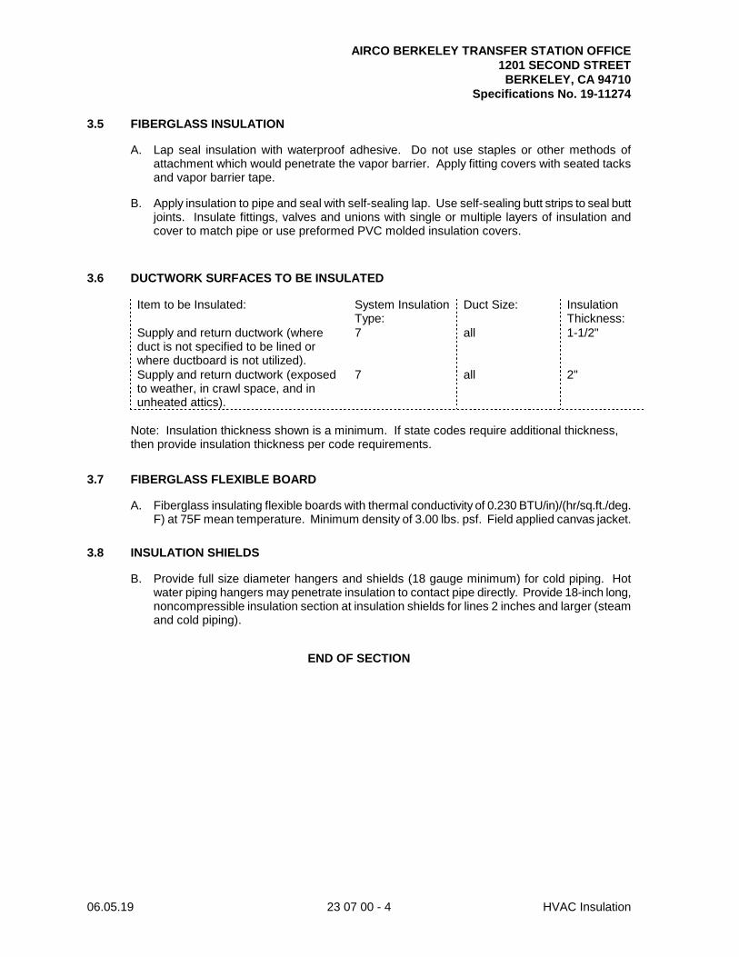
AIRCO BERKELEY TRANSFER STATION OFFICE 1201 SECOND STREET BERKELEY, CA 94710
Specifications No. 19-11274
06.05.19 23 07 00 - 4 HVAC Insulation
3.5 FIBERGLASS INSULATION
A. Lap seal insulation with waterproof adhesive. Do not use staples or other methods of attachment which would penetrate the vapor barrier. Apply fitting covers with seated tacks and vapor barrier tape.
B. Apply insulation to pipe and seal with self-sealing lap. Use self-sealing butt strips to seal butt joints. Insulate fittings, valves and unions with single or multiple layers of insulation and cover to match pipe or use preformed PVC molded insulation covers.
3.6 DUCTWORK SURFACES TO BE INSULATED
Item to be Insulated: System Insulation Type:
Duct Size: Insulation Thickness:
Supply and return ductwork (where duct is not specified to be lined or where ductboard is not utilized).
7 all 1-1/2"
Supply and return ductwork (exposed to weather, in crawl space, and in unheated attics).
7 all 2"
Note: Insulation thickness shown is a minimum. If state codes require additional thickness, then provide insulation thickness per code requirements.
3.7 FIBERGLASS FLEXIBLE BOARD
A. Fiberglass insulating flexible boards with thermal conductivity of 0.230 BTU/in)/(hr/sq.ft./deg. F) at 75F mean temperature. Minimum density of 3.00 lbs. psf. Field applied canvas jacket.
3.8 INSULATION SHIELDS
B. Provide full size diameter hangers and shields (18 gauge minimum) for cold piping. Hot water piping hangers may penetrate insulation to contact pipe directly. Provide 18-inch long, noncompressible insulation section at insulation shields for lines 2 inches and larger (steam and cold piping).
END OF SECTION
AIRCO BERKELEY TRANSFER STATION OFFICE 1201 SECOND STREET BERKELEY, CA 94710
Specifications No. 19-11274
06.05.19 23 31 00 - 1 Ductwork
SECTION 23 31 00
DUCTWORK
PART 1 - GENERAL
1.1 SUMMARY
A. Materials, installation and testing of HVAC ductwork and accessories, including the following:
1. Heating and air conditioning supply and return systems.
2. Exhaust systems.
3. Ductwork hangers.
1.2 QUALITY ASSURANCE
A. Unless otherwise noted, where the Specification refers to SMACNA in reference to sheet metal or flexible ductwork, this refers to HVAC Duct Construction Standards, Metal and Flexible, latest edition, as published by SMACNA.
B. Unless otherwise noted, where the Specification refers to TIMA in reference to fiberglass ductwork, this refers to Fibrous Glass Duct Construction Standards, latest edition, as published by TIMA.
C. Provide duct systems per local building codes, latest edition, and all referenced standards.
D. Have available at the project field office a copy of the referenced standards.
1.3 SUBMITTALS
A. Provide shop drawings for duct materials, flues.
B. Submit duct pressure testing reports. Provide individual reports for each AHU duct system.
1.4 AIR DISTRIBUTION DUCT SYSTEM
A. General: All ductwork, including collars, register boxes, fire dampers, exhaust fans, ventilation louvers, roof vents and screens, as well as all dampers and any other miscellaneous items not specifically mentioned but necessary for a complete installation. Apply the latest standards of SMACNA and ASHRAE with respect to sheet-metal gauge and general construction for round and rectangular ducts.
PART 2 - PRODUCTS
2.1 GALVANIZED SHEET-METAL DUCTWORK
A. General: IMC Duct Construction Standards, latest edition, or latest edition of ASHRAE Guide Table. 1-1/2 ounce galvanizing per square foot, both sides. G90 steel.
2.2 FLEXIBLE DUCTS
A. General: Comply with local building codes, latest edition, Class 0 or Class 1.
AIRCO BERKELEY TRANSFER STATION OFFICE 1201 SECOND STREET BERKELEY, CA 94710
Specifications No. 19-11274
06.05.19 23 31 00 - 2 Ductwork
B. Standard factory fabricated product, construct an inner wall of impervious vinyl or chlorinated polyethylene, permanently bonded to a vinyl or zinc-coated spring steel helix. Cover the assembly with fiberglass blanket insulation covered by an outer wall of vinyl or fiberglass-reinforced metalized vapor barrier. UL 181 listed Class 1 flexible air duct material. Overall thermal transmission no more than 0.25 (BTU/in)/(hr/sq.ft./deg. F) at 75F differential, per ASTM C335. Vapor transmission value no more than 0.10 perm, per ASTM E96. Rated for a minimum of 4-inch w.g. positive pressure and 1-inch w.g. negative pressure.
C. Air friction correction factor of 1.3 maximum at 1000 FPM. Working air velocity of at least 2000 FPM. Flame spread rating no more than 25. Smoke development rating no more than 50 as tested per ASTM E84. Must have cataloged data on insertion loss characteristics, minimum attenuation of 29 DB for 10-foot straight length at 8-inch diameter and 500 Hz.
D. Manufacturers: J. P. Lamborn Co., Norflex, Clevaflex, Genflex, Atco, Flexmaster, Thermaflex, or approved.
2.3 FACTORY FABRICATED METAL ROUND AND FLAT OVAL DUCTWORK
A. General: Provide per local building codes Duct Construction Standards, latest edition, and ASTM A527 Class 0.
B. Round sheet metal, spiral lock seam type. Fittings: Same construction as the duct. Tap in fittings not allowed. Duct sealer: Specifically formulated for sealing field joints for round spiral lock-seam duct systems.
2.4 SHEET-METAL DUCT SEALER
A. Hardcast "Duct-Seal 321" or United McGill. Indoor/outdoor, low VOC (<80 grams/liter), water based with fiber reinforcement.
2.5 PREFABRICATED DUCT JOINTS
A. Manufactured flanged traverse rectangular and round duct joints.
B. Manufacturers: Ductmate, Mez, Ward Duct Connectors, Lockformer TDC, or approved.
PART 3 - EXECUTION
3.1 INSTALLATION
A. The duct layout shown on the Contract Drawings is diagrammatic in nature. Coordinate the ductwork routing and layout, and make alterations to the ductwork routing and layout as required to eliminate physical interferences. Where deviations in the ductwork routing as shown in the Contract Drawings are required, such alterations not to compromise the air flow, pressure drop, and sound characteristics of the duct fitting or run as shown on the Contract Drawings. Make such determination by Architect. In the event Architect determines that the installed ductwork is inconsistent with the above mentioned criteria, remove and replace at no additional cost to the Owner.
B. Install ductwork in the location and manner shown and detailed. Review deviations required by job conditions with Architect prior to any fabrication. Provide fittings construction per SMACNA.
AIRCO BERKELEY TRANSFER STATION OFFICE 1201 SECOND STREET BERKELEY, CA 94710
Specifications No. 19-11274
06.05.19 23 31 00 - 3 Ductwork
C. Connect duct assemblies such as ductwork, plenums, etc., and operating machines or mechanisms such as fans, air conditioners, etc., with flexible connections per Section 23 05 48, Vibration and Seismic Controls for HVAC Piping and Equipment.
D. Fabricate radius elbows with centerline radius not less than 1-1/2 duct diameters.
E. Do not install duct size transition pitch angles which exceed 30 degrees for reductions in duct size in the direction of airflow, and 15 degrees for expansions in duct size in the direction of airflow.
F. Install single thickness turning vanes in square throat rectangular elbows and in tees. Provide 3/4-inch trailing edge on turning vanes, turned slightly past parallel to the duct. Use radius elbows in all exhaust applications (even where not shown as such on drawings) to avoid turning vanes within the exhaust air stream.
G. Duct sizes indicated are free inside dimensions including where internal lining is shown.
H. Provide G90 galvanized sheet-metal duct material for all ducts unless otherwise indicated or specified.
I. Provide temporary closures of open ducts with sheetmetal caps during construction to prevent dust and debris from entering the system. Where ductwork is to be left open for 48 hours or less, visqueen may be used.
J. Flexible Duct:
1. Install flexible duct with bend radius equal to 1.5 times the diameter. Minimum length 2 feet. Maximum length 5 feet, unless noted otherwise.
2. Provide round neck grilles/diffusers or square-to-round transitions. No flex duct connections directly to square neck allowed.
3. Flex duct allowed only for vertical drops to diffusers. Maximum offset angle from vertical: 30 degrees.
4. Flex duct allowed in concealed spaces above lay-in ceilings only. All areas above hard lid ceilings to be rigid duct connections made with sheetmetal.
5. Where using flexible ductwork to provide temporary air distribution due to phasing, flexible ductwork to be fully supported as if a permanent installation.
K. Fabricate ductwork and all sheet metal work of prime grade, lock forming quality steel in accordance with the current issues of the ASHRAE "Guide" and SMACNA standards and installed in strict conformance with SMACNA standards. Stainless duct to be continuous welded construction.
L. Submit shop drawings for approval for all ductwork.
M. Construct ductwork upstream of terminal unit boxes for 4-inch pressure class; downstream duct 1-inch pressure class. All other duct 2-inch pressure class.
N. Round spiral duct and fittings or where required due to available clearances, use flat oval ductwork and fittings upstream of terminal units manufactured by United Sheet Metal, Rolok or approved in accordance with ASTM A527.
O. Seal all joints and seams in supply, exhaust, and return air ductwork and plenums.
P. Fabricate ductwork and plenums with a smooth inside surface and support and brace to prevent sagging and vibration at any time. Provide galvanized steel angles for reinforcing and bracing.

AIRCO BERKELEY TRANSFER STATION OFFICE 1201 SECOND STREET BERKELEY, CA 94710
Specifications No. 19-11274
06.05.19 23 31 00 - 4 Ductwork
Q. Joints:
1. Carefully cut and trim all joints and seams in fabricated ducts and fitting to form a closed joint with no portion of the duct or fitting protruding into the air stream.
2. Seal all joints in sheet-metal ducts in concealed locations (such as enclosed ceiling spaces) with Hardcast joint sealant system applied in accordance with manufacturer's recommendations, or use Ductmate-type joints.
3. Seal all joints in sheet-metal ducts in exposed locations with sealant system applied in accordance with manufacturer's recommendations. Wipe off excess sealer on duct to give a clean finish, or use Ductmate-type joints.
4. To connect sheet-metal ductwork to fiberglass ductboard, use Hardcast only.
5. Standard gray duct tape not allowed.
R. All fasteners such as sheet-metal screws, machine screws or rivets to be cadmium plated.
S. Crimp flat duct surfaces diagonally or beaded regardless of size, unless acoustically lined.
T. Fabricate all duct size transitions with a slope of not more than 1 foot to 5 feet where possible, but in no case more than 1 foot in 3 feet.
U. Fabricate duct turns with the inside (smallest) radius at least equal to the duct width. Where necessary, square elbows may be used, with maximum available inside radius and with fixed single thickness curved vanes, with trailing edge extended 3/4 inch.
V. Provide flexible connectors at connections to all equipment, in ducts crossing building expansion joints and may be used at connections of dissimilar metals. Flexible Connections: Minimum 16 ounce airtight "Ventglass" noncombustible fabric with fire retardant neoprene coating on outside, fastened with bolted galvanized steel bands. Maintain a minimum 1-inch space between the connecting surfaces.
W. Duct Hangers and Supports:
1. Hang rectangular sheet-metal ducts with a cross sectional area of less than 7 sq.ft. with galvanized strips of No. 16 USS gauge steel 1 inch wide, and all larger ducts with steel angles and adjustable hanger rods similar to piping hangers. Support at 8 feet on center, as detailed.
2. Anchor all ducts securely to building in such a manner as to prevent transmission of vibration to structure. Do not connect duct hanger straps to roof deck. Do not support ducts from other ducts or piping.
3. For round sheet-metal ducts, provide duct support in accordance with SMACNA Guidelines. Verify type of building construction.
4. Attach strap hangers installed flush with end of sheet-metal duct run to duct with sheet-metal screws.
5. Do not install duct stiffeners on interior (air side) of unlined ductwork; install on exterior only or on interior of ductwork with duct liner.
6. Seismic Restraint: Brace all ductwork against lateral movement as detailed in document "Seismic Restraint Manual Guidelines for Mechanical Systems" as published by SMACNA.
X. Ductwork not to be supported from the roof deck. Hang ducts from beams, joists or supplementary structural members provided by Contractor. Do not hang ductwork from joist bridging or from other ducts.
AIRCO BERKELEY TRANSFER STATION OFFICE 1201 SECOND STREET BERKELEY, CA 94710
Specifications No. 19-11274
06.05.19 23 31 00 - 5 Ductwork
Y. Although not necessarily indicated on the Drawings, provide turning vanes at all mitered elbows, opposed blade balancing dampers with locking quadrants at branch ducts, volume extractors and any other applicable devices necessary for minimum duct resistance and proper system air balancing. Sufficiently stiffen all dampers to prevent noise or vibration and in no case be lighter than 20 gauge steel. Provide with accessibly located adjuster, manufactured by Young Regulator Co., Parker Kalon Corporation, or approved.
Z. Construct all exterior ductwork or ductwork which is otherwise exposed to weather watertight. Slope ductwork to allow water to sheet off the ductwork.
AA. Locate access doors in ductwork as required for service of fire dampers, automatic dampers and other items requiring maintenance or inspection.
BB. Paint inside surface of all bare ductwork which is visible through face of grilles with flat black paint for all ceilings 12 feet and lower.
CC. Smoke Detectors: Mount in duct per listing requirements, with detector in serviceable location. Adjust duct layout as required to meet velocity and clearance listing.
3.2 DUCTWORK PRESSURE TESTING
A. Test ductwork prior to connection to fan equipment. Repair leaks and retest until stipulated results are achieved. All pressure testing to meet the following leakage classes below as a minimum (ASHRAE Chapter 21, Table 6):
1. Leakage class to be as defined below as a minimum.
Minimum Duct Leakage Classification
Duct Type Leakage Class
Metal (flexible excluded)
Round and flat oval 3
Rectangular
≤2 inches of water 12
(both positive and negative pressures)
>2 and ≤10 inches of water 6
(both positive and negative pressures)
2. Test at positive static pressure for 5 minutes with maximum air leakage not to exceed 1 percent of rated flow.
3. Testing machine: Meet requirements of SMACNA standards. Pacific Air Products "Port-O-Lab," Rolok, United Sheet Metal, or approved.
4. Test supply systems prior to connecting VAV boxes.
5. Perform all tests in the presence of Owner's Representative. Give 48 hours advance notice before commencement of each test.
6. Test ductwork systems in sections as large as possible and record all test results according.
7. Coordinate testing with ceiling installation.
a. Provide sheet-metal plates and install between each duct test section (applies to main-to-main fittings, branch-to-branch fittings and main-to-branch fittings). At each
AIRCO BERKELEY TRANSFER STATION OFFICE 1201 SECOND STREET BERKELEY, CA 94710
Specifications No. 19-11274
06.05.19 23 31 00 - 6 Ductwork
plate location, fabricate joint with Ductmate. Insert 14 gauge sheet metal between Ductmate using a neoprene gasket on both sides of metal plate.
b. Leave plates in place until isolated section has been tested and approved by Owner's Representative.
c. Once sections have passed test, remove plates and reattach Ductmate joints. After fan unit is running, test joint for leakage by using a mixture of soap and water. If any noise or bubbling occurs, reseal joint. Owner's representative to witness this procedure.
B. Install all sidewall return air grilles for "sight-tight" visibility at eye level (position blades to obscure visibility from floor level).
3.3 GRILLE AND EXPOSED DUCT CLEANING
A. After completion of ductwork installation, operate each fan system (excluding exhaust fans) for a minimum of 30 minutes prior to installation of ceiling grilles and diffusers. After grilles and diffusers are installed, clean out all accumulation of particles from grilles and diffusers prior to acceptance.
B. Clean exterior surface of all ducts exposed to public view of chalk, pencil and pen marks, labels, sizing tags, dirt, dust, etc., so that upon completion of installation, ducts are left in clean and unblemished manufactured condition.
C. All exposed duct and grilles shall remain free of dust entrained streaks due to leakage at joints and grille connections during warranty period. Clean leaks, seal and refinish to match existing if visible streaks develop.
END OF SECTION
AIRCO BERKELEY TRANSFER STATION OFFICE 1201 SECOND STREET BERKELEY, CA 94710
Specifications No. 19-11274
06.05.19 23 33 00 - 1 Ductwork Accessories
SECTION 23 33 00
DUCTWORK ACCESSORIES
PART 1 - GENERAL
1.1 SUMMARY
A. Work Included: Materials, installation, and testing of HVAC duct accessories such as volume dampers, splitter dampers, adjustable deflectors, duct access doors, backdraft dampers, fire dampers, duct silencers, spin-in fittings, and smoke dampers.
1.2 QUALITY ASSURANCE
A. Provide fire dampers in conformance with the requirements of Fire Damper and Heat Stop Guide for Air Handling Systems, as published by SMACNA.
1.3 SUBMITTALS
A. Submit manufacturer's catalog data and fabrication/installation drawings for each factory fabricated duct accessory.
PART 2 - PRODUCTS
2.1 DAMPERS
A. Volume Dampers (VD):
1. Construct of galvanized sheets not lighter than 18 gauge, reinforced to prevent vibration, equipped at both ends with brass bearing mounts and of sufficient length to provide a complete shutoff of the duct.
2. Provide each damper with an adjustment and locking quadrant device manufactured by Young Regulator Co., No. 403 operator for accessible locations, or No. 315 for nonaccessible locations. Ventlock, or approved. Provide operating rod and attaching devices as required for No. 315 operator. Provide Young Regulator No. 443 or 443B raised platform for insulated duct.
B. Register Dampers: Dampers utilized with grilles. Opposed blade dampers utilizing a side operated worm drive which provides external duct operation. Slot the end of the shaft to receive a screwdriver. Factory assembled side operator. Construct of the same material as the grille. Manufacturers: Same as grilles and diffusers. Provide Young Regulator 443 or 443B raised platform for insulated duct.
2.2 ADJUSTABLE DEFLECTORS
A. Manufacturers: Titus, Aero-Dyne, or approved.
B. Adjustable deflectors and adjustable turning devices for diverting airflow from a main duct into a branch duct: Multiblade assembly hinged at one end and so constructed that, as it is closed, the air passage between the blades narrows until no air passage remains when the assembly is in the fully closed position.
C. Construct of the same material as the ductwork in which they are installed.
AIRCO BERKELEY TRANSFER STATION OFFICE 1201 SECOND STREET BERKELEY, CA 94710
Specifications No. 19-11274
06.05.19 23 33 00 - 2 Ductwork Accessories
2.3 DUCT ACCESS DOORS
A. Gasketed, hinged or removable, rated for operating pressure. Ductmate "Sandwich" for rectangular ductwork or "Metu" for round ductwork, or approved.
PART 3 - EXECUTION
3.1 VOLUME DAMPERS
A. Provide in main duct branches where shown. Provide in branch ducts serving air inlets and outlets.
B. Locate dampers as close to trunk or main branch as possible.
3.2 DUCT ACCESS DOORS
A. Install where shown and required by SMACNA. Provide on the reset side of all fire dampers and adjacent to duct mounted automatic dampers. Install per manufacturer's recommendations. Provide colored ceiling pin below damper to identify its location.
B. Where access doors are for service of fire or smoke dampers, stencil the words "Fire Damper" or "Smoke Damper" in 1/2-inch high capital letters on the outside of the door.
END OF SECTION
AIRCO BERKELEY TRANSFER STATION OFFICE 1201 SECOND STREET BERKELEY, CA 94710
Specifications No. 19-11274
06.05.19 23 37 00 - 1 Air Outlets and Inlets
SECTION 23 37 00
AIR OUTLETS AND INLETS
PART 1 - GENERAL
1.1 SUMMARY
A. Work Included: Materials, installation, and testing of HVAC outlets and inlets.
1.2 QUALITY ASSURANCE
A. Components: Tested, rated and certified per Air Diffusion Council procedures.
B. Air Movement and Control Association Int'l (AMCA) Compliance: Test and rate louvers in accordance with AMCA 500, "Test Method for Louvers, Dampers and Shutters." Provide louvers bearing AMCA Certified Rating Seal.
1.3 SUBMITTALS
A. Manufacturer's catalog data on each of the following:
1. Type of register, diffuser, grille, frame, louver, and dampers.
2. Schedule of air outlets and inlets indicating drawing designation, model number and accessories furnished.
3. Louvers: Performance data indicating face area, free area velocity, and corresponding pressure drop and water penetration data.
PART 2 - PRODUCTS
2.1 GRILLES, REGISTERS, DIFFUSERS
A. Subject to compliance with requirements, provide products of one of the following.
B. Provide 1-, 2-, 3-, or 4-way deflection as indicated.
C. Coordinate mounting frames with construction types per finish schedule.
D. Performance: Provide components that have velocity, throw and drop, and noise criteria ratings for each size device as listed in manufacturer's current standard literature, which are plus or minus 10 percent of the components as listed in the Diffuser, Register and Grille Schedule, or as specified herein.
E. Manufacturers: Titus, Price, Metal Air, Krueger, or approved equal. (See schedule for Model).
AIRCO BERKELEY TRANSFER STATION OFFICE 1201 SECOND STREET BERKELEY, CA 94710
Specifications No. 19-11274
06.05.19 23 37 00 - 2 Air Outlets and Inlets
PART 3 - EXECUTION
3.1 INSTALLATION
A. Install grilles, registers, and diffusers per manufacturer's instructions. Locate and size openings through finished surfaces to provide complete coverage of rough openings by integral device flanges or auxiliary frames.
B. Paint exterior of devices per color selected by Architect.
C. Coordinate duct connections with device final dimensions. Provide square to round adapters where required for connection to round ducts.
D. Adjust the throws of air outlets to eliminate drafts.
3.2 SUPPLY, RETURN, AND EXHAUST REGISTERS
A. Coordinate connection or placement of air registers with other ceiling-mounted fixtures such as light fixtures, signs, smoke detector, sprinkler heads, speakers, etc.
END OF SECTION
AIRCO BERKELEY TRANSFER STATION OFFICE 1201 SECOND STREET BERKELEY, CA 94710
Specifications No. 19-11274
06.05.19 26 00 00 - 1 Electrical
SECTION 26 00 00
ELECTRICAL PART 1 - GENERAL 1.01 RELATED DOCUMENTS
A. The General Conditions, Supplementary General Conditions and Division 1 - General Requirements are a part of this section and the contract for this work and apply to this section as fully as if repeated herein.
1.02 SCOPE
A. The scope of work shall include all labor, materials, equipment and services necessary for and properly incidental to the complete furnishings and installation of all electrical work as shown on the drawings and as herein specified, including the following:
1. Lighting system. Re-using existing light fixtures and re-arranging to new space
program.
2. Addition to existing emergency lighting system and illuminated exit sign system.
3. A system of utility outlets, receptacles, motor outlets, and connections and other services to equipment specified under other divisions.
4. Support systems for electrical equipment.
5. Interface with electrical equipment furnished by the Owner as noted on drawing
and within these specifications.
6. Flashing of all conduits where they pierce the roof or other waterproof membranes, and all cutting and patching necessary to complete the work.
1.03 RELATED WORK SPECIFIED IN OTHER SECTIONS
A. Equipment and certain control devices. See Architectural Division.
B. Painting of support systems and conduits as described in Painting Section under architectural division.
1.04 INTENT OF SPECIFICATIONS
A. In the Specifications, Drawings, schedules and details, information is conveyed by means of brief mention or notation which, regardless of brevity, shall be binding exactly as if presented in complete sentences employing mandatory language. Work not explicit in the Specifications or Drawings but clearly implied as necessary to complete the systems shall be included as though fully specified and drawn.
1.05 DRAWINGS AND COORDINATION
A. Drawings are diagrammatic and show general arrangement except where specifically dimensioned. Study Drawings and premises to determine the best methods, exact locations, routing and arrangement for the work.
AIRCO BERKELEY TRANSFER STATION OFFICE 1201 SECOND STREET BERKELEY, CA 94710
Specifications No. 19-11274
06.05.19 26 00 00 - 2 Electrical
B. Existing building conditions, locations and services, and all requirements of the serving utilities shall be coordinated with the Drawings and Specifications. These conditions and requirements shall be included under this Section of the Work.
C. Install equipment to avoid obstructions, preserve headroom and to keep openings and
passageways clear. Keep conduits within furring lines established on the Architectural Drawings unless shown exposed. Provide sleeves and chases where conduits pass through floors or walls. Should additional opening spaces be required, locate and arrange for in time to avoid unnecessary cutting.
D. Cooperation among the trades is necessary for proper execution of the work as a whole.
Conflicts within the Contract Documents shall be referred to the Architect for clarification before the work is installed. Contractor shall bear cost of delay due to unresolved conflicts.
E. Existing installation shown in approximate location and assumed condition only.
Contractor shall verify in field before commencing work. 1.06 REGULATIONS
A. All work and materials shall be in full accordance with the applicable City and County Codes and with the latest rules and regulations of the State Fire Marshal, Title 24 of the California Administrative Code, the Safety Orders of the Division of Industrial Safety, California Electrical Code, N.F.P.A. (Life Safety Code) and other applicable State laws and regulations. Nothing in the Contract Documents is to be construed to permit work not conforming to these codes.
B. Nothing in the specifications or drawings permits violation of such directives, and where
conflict occurs, the directives shall govern, except where superior work is specified or indicated. Such conflicts shall be brought to the Architect's attention for clarification, prior to the submission of the bid. If minor changes or additions to the work are required by the State after award of the contract, these shall be included at no additional cost to the Owner.
1.07 PERMITS, FEES AND LICENSES
A. The Contractor shall provide, procure and pay all permits, licenses, fees, etc., required to carry on and complete this work.
1.08 SUBMITTALS OF MATERIAL AND SHOP DRAWINGS
A. Mention of Brand or Trade names includes the phrase "or approved equal", unless specifically noted as "no equal".
B. Materials shall be new standard and the best quality of their respective kinds for the
purpose, intended and satisfactory to the Architect. Deliver materials to and store them at the project in unbroken container. Use only one brand, kind and make of materials for each purpose throughout the work. Brand or trade names are used to set standards of quality. No substitute materials may be used, unless approved in writing by the Architect.
C. Within 30 days after award of Contract, submit 5 copies of a complete list of all materials
to be used on the project, specifying manufacturer, grade, trade name, and catalog number. Any proposed substitutions shall be accompanied by blueprints and/or data giving size, capacity, and other pertinent information concerning proposed substitutions. Samples shall be furnished if required by Architect or his representatives. Material list
AIRCO BERKELEY TRANSFER STATION OFFICE 1201 SECOND STREET BERKELEY, CA 94710
Specifications No. 19-11274
06.05.19 26 00 00 - 3 Electrical
shall be complete. Partial list not acceptable.
D. Shop Drawings shall show:
1. Physical size and arrangement of equipment.
2. Wiring diagrams of all equipment showing all circuit devices, conductor sizes, type, etc.
3. Specifications of all components including finishes.
E. Furnish shop drawings and/or equipment cuts for the following:
1. Disconnect Switches and breakers
2. Panelboards
3. Load monitoring equipment
F. Furnish five (5) copies of lighting fixture cuts (in brochure form with indexed flyleaf in
front). Where multiple types or catalog numbers are shown on sheets, underline or suitably identify proposed fixtures.
1.09 EXAMINATION ON SITE
A. Examine the site and premises prior to bidding, to determine the conditions under which the work is to be performed. No allowances will be made for extra expense incurred due to failure to examine the premises or to discover site conditions which affect the work.
1.10 CONFERENCE WITH ARCHITECT
A. Confer with the Architect to confirm exact locations, mounting heights and arrangements of all finish work prior to roughing in. Minor relocations and rearrangements of the work requested at this time shall be included at no additional cost to the Owner.
1.11 SUPERVISION AND WORKMANSHIP
A. Workmanship shall be first class throughout and performed only by competent and experienced workmen in a manner satisfactory to the Architect. Constant supervision of the work either by the Contractor or his competent representative shall be maintained.
B. Work may be inspected at any time by the Architect or his representative. Work covered
or concealed before being inspected and approved shall be opened and uncovered upon request.
1.12 WORK IN EXISTING BUILDING
A. Existing building electrical equipment may be reused to the fullest extent possible to accomplish the work indicated. Contractor shall make corrections as necessary, take the existing installation as found, and complete the work without additional cost to the Owner. The existing systems shall be maintained or returned to original operating condition. Such portions of the existing systems damaged during the course of this construction shall be restored to original condition.
AIRCO BERKELEY TRANSFER STATION OFFICE 1201 SECOND STREET BERKELEY, CA 94710
Specifications No. 19-11274
06.05.19 26 00 00 - 4 Electrical
1.13 DEMOLITION
A. Shall be provided as required to accommodate new work called for and as noted. Work shall be done carefully to avoid damage to the surfaces, structure and equipment not being replaced.
1.14 SERVICE INTERRUPTIONS
A. Interruption of power service, if required, shall be held to a minimum. Any interruption must be scheduled in writing with the Owner, two (2) weeks in advance and must meet with their approval.
1.15 AS-BUILT DRAWINGS
A. Obtain and pay for and keep up to date and available to the Architect or his representative, complete blue line prints of the project, drawings clearly annotated with "as-built" data as the work is performed; this data shall include exact sizes, locations of services, disconnects as installed.
B. These drawings shall become a part of the requirements for progress payment. Upon
completion of the project, the information shown on these drawings shall be transposed to a complete set of reproducible furnished by the Architect, paid for by the Contractor to become the Owner's record of the work. The drawings shall be certified to be correct by the Contractor preparing them and receipt of approved "as-built" reproducible shall be a condition for final acceptance.
1.16 INSTRUCTIONS
A. The Contractor shall furnish four (4) copies of complete installation, servicing and operational instructions, including schematic and wiring diagrams for all systems to the Architect.
1.17 CERTIFICATE AND WARRANTY
A. As a condition of final acceptance, deliver to the Architect two (2) complete bound sets of manufacturer's certificates, warranty slips, part lists, descriptive brochures and maintenance instructions for all equipment installed; properly tabbed and identified for easy reference in accordance with the provisions of the General Conditions and Division 1.
PART 2 - PRODUCTS 2.01 GENERAL
A. Materials new, packed in original containers, installed and turned over to Owner free of defects.
B. Materials bear Underwriters' Laboratory label except equipment which UL does not list or
provide label service.
C. Furnish equipment, materials for any one system by same manufacturer. Such items as lamps, conduit fittings, wire, wiring devices, etc.: same brand throughout project.
AIRCO BERKELEY TRANSFER STATION OFFICE 1201 SECOND STREET BERKELEY, CA 94710
Specifications No. 19-11274
06.05.19 26 00 00 - 5 Electrical
D. Make materials installed outside building weathertight, of design intended for this purpose. Galvanize all ferrous exterior materials or zinc-phosphatized (Bonderized) and baked-enamel coated.
2.02 RACEWAYS
A. Conduit - electric metallic tubing: by same manufacturer as conduit. Galvanized or sherardized. Fittings - Duro or Thomas & Betts. Provide connectors with plastic insulated throats. Couplings and connectors sized 3/4- inch and less - set screw ; couplings and connectors sizes 1-inch and above threaded compression type (watertight) only. Ream all cuts.
B. Rigid steel – as manufactured by Walker, National, Appleton, Triangle, Rome, General
Electric. Rigid steel: galvanized or sherardized. All fittings threaded. Bends 1 1/4 inches or larger: factory, running and exposed threads not permitted. Ream all cuts.
C. Flexible conduit - same manufacturer as conduit. Galvanized steel. Fittings: "Jake" as
manufactured by W.F. Curlee Manufacturing Company.
D. Liquid tight flexible conduit as manufactured by: American Brass, Sealtight, Type U.A. Fittings: Appleton Series "ST" only.
2.03 POWER CABLE
A. As manufactured by: Okonite, Anaconda, General Electric, General Cable, Simplex or Rome.
B. Provide high temperature wires where required by ambient temperature conditions. Type
RHH or THHN 90 degree centigrade stranded used for fixture wire and circuit runs within fixtures.
C. Cable size No. 6 and larger, all exterior underground wiring: Type THW or THWN, 600
volt, copper.
D. All other cable 600 volt size No. 8 and smaller: Type THWN solid copper.
E. All cable No. 6 and larger: stranded.
F. Pull wire in empty raceways: Nylon pull cord
G. Concealed in framing: Metallic conduit.
H. Pulling lubricants: "Ideal" - yellow.
I. Wires No. 10 and smaller splice with insulated "Scotchloks". Wires No. 8 and larger with Burndy "Hydent" connectors.
J. Tag wiring with Brady "Quick" labels at all pull boxes, junction boxes and panelboards.
K. Identify all branch circuits contained in junction boxes and outlet boxes with permanent
black markers.
AIRCO BERKELEY TRANSFER STATION OFFICE 1201 SECOND STREET BERKELEY, CA 94710
Specifications No. 19-11274
06.05.19 26 00 00 - 6 Electrical
L. Color code all wire as follows:
Phase 120/208 Volt System
A Black B Red C Blue Neutral White All Ground Wires Green
2.04 OUTLET AND PULL BOXES
A. As manufactured by Steel City, Pyle National, Appleton, Raco Killark, Hope & Bowers.
B. Exterior wall surfaces or otherwise exposed to weather: cast aluminum FD boxes with threaded hubs, neoprene gaskets and aluminum cover.
C. Other outlet boxes: One piece stamped steel galvanized. Minimum boxes size: 4-inch
octagon or square. Plaster rings, extensions provided where necessary.
D. Pullcans: Construct of code gauge galvanized sheet steel with screw cover. Finish same as panelboards. Size per N.E.C.
2.05 SUPPORT SYSTEMS
A. As manufactured by: Unistrut, Kindorf or Powerstrut.
B. Clamps: One hole malleable iron. Multiple runs: supported on Unistrut P-1000 or P-4000 channel with conduit clamps. Suspended trapezes: Unistrut P-1000 galvanized.
C. Suspended single conduit: pendant threaded rod with pipe clamp.
2.06 WIRING DEVICES
A. As manufactured by: Arrow-Hart, P&S, Bryant, Sierra, Harvey Hubbell.
B. Devices as follows: (Numbers refer to Harvey Hubbell, except as noted).
1. Single pole switch 1221 W 2. Three way switch 1223 W [I] 3. Duplex receptacle with GFI GF-5262-W 4. Duplex receptacle 20A,
3 PG, 125V 5362-W [I] 5. Duplex receptacle,
Weatherproof 5214 6. Disconnect switch Square D, 240V
Heavy Duty HP rated
7. Manual starter, surface Square D Class mounted 2510FG-1
8. Manual starter, flush Square D Class mounted 2510FS-1
AIRCO BERKELEY TRANSFER STATION OFFICE 1201 SECOND STREET BERKELEY, CA 94710
Specifications No. 19-11274
06.05.19 26 00 00 - 7 Electrical
2.07 DEVICE PLATES
A. Provide for each wall switch, receptacle, or other outlet. Plates in finished areas: Sierra white nylon plastic, smooth line. Exposed boxes in unfinished areas: galvanized steel raised plates. Junction boxes or unused outlets provided with blank plates. Switches or other units in gang or tandem boxes provided with one piece gang or tandem plates.
2.08 LIGHT FIXTURES
A. Re-use existing light fixtures. See floor plans. 2.09 TELEPHONE OUTLET AND WIRING SYSTEM
A. Furnish and install an addition to existing telephone outlet and wiring system ready for connection of telephone devices.
B. Outlets: Surface type with modular plug (RJ-14) for telephone.
C. Telephone cable, category 3 type run directly to main telephone board or to designated
telephone terminal cabinet as shown on plans. 2.10 TELEPHONE RACEWAY SYSTEM
A. Furnish and install raceway system for installation of telephone system.
B. Raceways: Sizes as noted on the drawings with maximum two 1/4 bends between outlets.
C. Outlets: 4" square with single gang ring and one hole bushed coverplate.
D. Provide pull cord in each raceway.
E. Installation of telephone handset equipment by others.
PART 3 - EXECUTION 3.01 INSTALLATION - GENERAL
A. Install work neatly. Raceways, fittings, equipment level, plumb straight. Connectors, locknuts, screws, clamps, joints made up tightly.
B. Conduit, outlets, equipment: Install to clear beams or obstructions. Do not cut or reduce
size of any load carrying member without written approval.
C. Adjacent wall mounted wiring devices, room thermostats or other equipment to be located at same elevation or in line one above the other. (See Architectural Drawings and Electrical Drawings).
3.02 INSTALLATION - RACEWAY
A. Install conduit in concrete parallel to principal reinforcing steel. Maximum size raceway permitted in structural concrete: 3/4-inch trade size or as directed.
B. Exposed raceways run parallel or at right angles to building walls or ceiling.
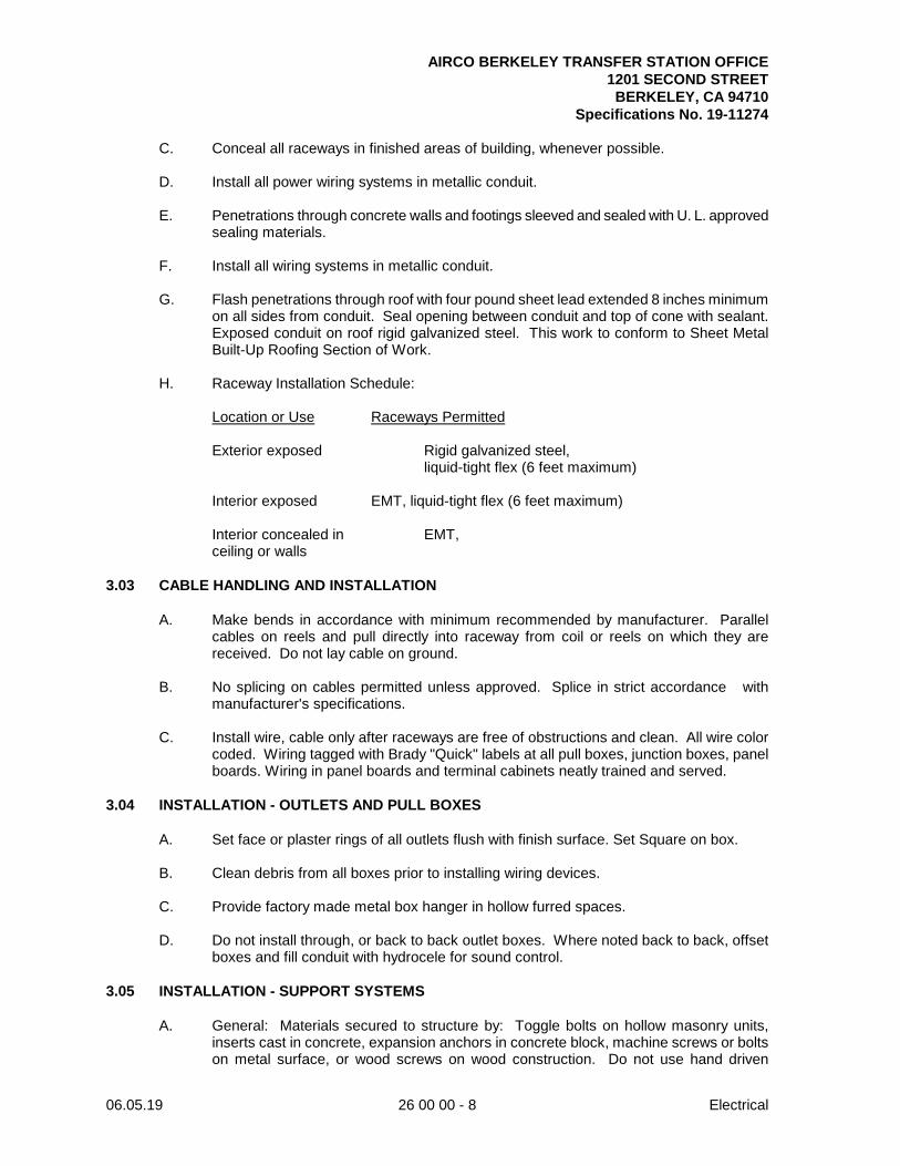
AIRCO BERKELEY TRANSFER STATION OFFICE 1201 SECOND STREET BERKELEY, CA 94710
Specifications No. 19-11274
06.05.19 26 00 00 - 8 Electrical
C. Conceal all raceways in finished areas of building, whenever possible.
D. Install all power wiring systems in metallic conduit.
E. Penetrations through concrete walls and footings sleeved and sealed with U. L. approved sealing materials.
F. Install all wiring systems in metallic conduit.
G. Flash penetrations through roof with four pound sheet lead extended 8 inches minimum
on all sides from conduit. Seal opening between conduit and top of cone with sealant. Exposed conduit on roof rigid galvanized steel. This work to conform to Sheet Metal Built-Up Roofing Section of Work.
H. Raceway Installation Schedule:
Location or Use Raceways Permitted
Exterior exposed Rigid galvanized steel,
liquid-tight flex (6 feet maximum)
Interior exposed EMT, liquid-tight flex (6 feet maximum)
Interior concealed in EMT, ceiling or walls
3.03 CABLE HANDLING AND INSTALLATION
A. Make bends in accordance with minimum recommended by manufacturer. Parallel cables on reels and pull directly into raceway from coil or reels on which they are received. Do not lay cable on ground.
B. No splicing on cables permitted unless approved. Splice in strict accordance with
manufacturer's specifications.
C. Install wire, cable only after raceways are free of obstructions and clean. All wire color coded. Wiring tagged with Brady "Quick" labels at all pull boxes, junction boxes, panel boards. Wiring in panel boards and terminal cabinets neatly trained and served.
3.04 INSTALLATION - OUTLETS AND PULL BOXES
A. Set face or plaster rings of all outlets flush with finish surface. Set Square on box.
B. Clean debris from all boxes prior to installing wiring devices.
C. Provide factory made metal box hanger in hollow furred spaces.
D. Do not install through, or back to back outlet boxes. Where noted back to back, offset boxes and fill conduit with hydrocele for sound control.
3.05 INSTALLATION - SUPPORT SYSTEMS
A. General: Materials secured to structure by: Toggle bolts on hollow masonry units, inserts cast in concrete, expansion anchors in concrete block, machine screws or bolts on metal surface, or wood screws on wood construction. Do not use hand driven
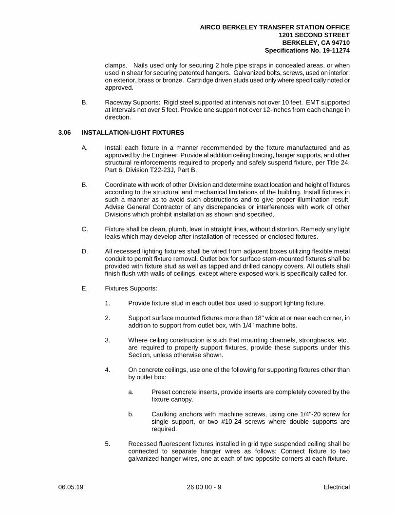
AIRCO BERKELEY TRANSFER STATION OFFICE 1201 SECOND STREET BERKELEY, CA 94710
Specifications No. 19-11274
06.05.19 26 00 00 - 9 Electrical
clamps. Nails used only for securing 2 hole pipe straps in concealed areas, or when used in shear for securing patented hangers. Galvanized bolts, screws, used on interior; on exterior, brass or bronze. Cartridge driven studs used only where specifically noted or approved.
B. Raceway Supports: Rigid steel supported at intervals not over 10 feet. EMT supported
at intervals not over 5 feet. Provide one support not over 12-inches from each change in direction.
3.06 INSTALLATION-LIGHT FIXTURES
A. Install each fixture in a manner recommended by the fixture manufactured and as approved by the Engineer. Provide al addition ceiling bracing, hanger supports, and other structural reinforcements required to properly and safely suspend fixture, per Title 24, Part 6, Division T22-23J, Part B.
B. Coordinate with work of other Division and determine exact location and height of fixtures
according to the structural and mechanical limitations of the building. Install fixtures in such a manner as to avoid such obstructions and to give proper illumination result. Advise General Contractor of any discrepancies or interferences with work of other Divisions which prohibit installation as shown and specified.
C. Fixture shall be clean, plumb, level in straight lines, without distortion. Remedy any light
leaks which may develop after installation of recessed or enclosed fixtures.
D. All recessed lighting fixtures shall be wired from adjacent boxes utilizing flexible metal conduit to permit fixture removal. Outlet box for surface stem-mounted fixtures shall be provided with fixture stud as well as tapped and drilled canopy covers. All outlets shall finish flush with walls of ceilings, except where exposed work is specifically called for.
E. Fixtures Supports:
1. Provide fixture stud in each outlet box used to support lighting fixture.
2. Support surface mounted fixtures more than 18" wide at or near each corner, in
addition to support from outlet box, with 1/4" machine bolts.
3. Where ceiling construction is such that mounting channels, strongbacks, etc., are required to properly support fixtures, provide these supports under this Section, unless otherwise shown.
4. On concrete ceilings, use one of the following for supporting fixtures other than
by outlet box:
a. Preset concrete inserts, provide inserts are completely covered by the fixture canopy.
b. Caulking anchors with machine screws, using one 1/4"-20 screw for
single support, or two #10-24 screws where double supports are required.
5. Recessed fluorescent fixtures installed in grid type suspended ceiling shall be
connected to separate hanger wires as follows: Connect fixture to two galvanized hanger wires, one at each of two opposite corners at each fixture.
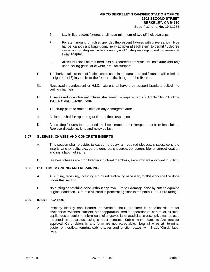
AIRCO BERKELEY TRANSFER STATION OFFICE 1201 SECOND STREET BERKELEY, CA 94710
Specifications No. 19-11274
06.05.19 26 00 00 - 10 Electrical
6. Lay-in flourescent fixtures shall have minimum of two (2) holdown clips.
7. For stem mount furnish suspended fluorescent fixtures with universal joint type hanger canopy and longitudinal sway adapter at each stem, to permit 45 degree swivel on 360 degree circle at canopy and 45 degree longitudinal movement at sway adapter.
8. All fixtures shall be mounted to or suspended from structure; no fixture shall rely
upon ceiling grids, duct work, etc., for support.
F. The horizontal distance of flexible cable used in pendant mounted fixture shall be limited to eighteen (18) inches from the feeder to the hanger of the fixtures.
G. Recessed incandescent or H.I.D. fixture shall have their support brackets bolted into
ceiling channels.
H. All recessed incandescent fixtures shall meet the requirements of Article 410-65C of the 1981 National Electric Code.
I. Touch-up paint to match finish on any damaged fixture.
J. All lamps shall be operating at time of final inspection.
K. All existing fixtures to be reused shall be cleaned and relamped prior to re-installation.
Replace discolorize lens and noisy ballast. 3.07 SLEEVES, CHASES AND CONCRETE INSERTS
A. This section shall provide, to cause no delay, all required sleeves, chases, concrete inserts, anchor bolts, etc., before concrete is poured, be responsible for correct location and installation of same.
B. Sleeves, chases are prohibited in structural members, except where approved in writing.
3.08 CUTTING, MARKING AND REPAIRING
A. All cutting, repairing, including structural reinforcing necessary for this work shall be done under this section.
B. No cutting or patching done without approval. Repair damage done by cutting equal to
original condition. Grout in all conduit penetrating floor to maintain 1- hour fire rating. 3.09 IDENTIFICATION
A. Properly identify panelboards, convertible circuit breakers in panelboards, motor disconnect switches, starters, other apparatus used for operation of, control of, circuits, appliances or equipment by means of engraved laminated plastic descriptive nameplates mounted on apparatus, using contact cement. Submit nameplates to Architect for approval. Cardholders in any form are not acceptable. Log all wires at terminal equipment, outlets, terminal cabinets, pull and junction boxes, with Brady "Quick" label tags.
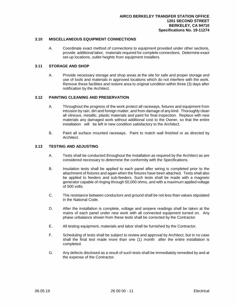
AIRCO BERKELEY TRANSFER STATION OFFICE 1201 SECOND STREET BERKELEY, CA 94710
Specifications No. 19-11274
06.05.19 26 00 00 - 11 Electrical
3.10 MISCELLANEOUS EQUIPMENT CONNECTIONS
A. Coordinate exact method of connections to equipment provided under other sections, provide additional labor, materials required for complete connections. Determine exact set-up locations, outlet heights from equipment installers.
3.11 STORAGE AND SHOP
A. Provide necessary storage and shop areas at the site for safe and proper storage and use of tools and materials in approved locations which do not interfere with the work. Remove these facilities and restore area to original condition within three (3) days after notification by the Architect.
3.12 PAINTING CLEANING AND PRESERVATION
A. Throughout the progress of the work protect all raceways, fixtures and equipment from intrusion by rain, dirt and foreign matter, and from damage of any kind. Thoroughly clean all vitreous, metallic, plastic materials and paint for final inspection. Replace with new materials any damaged work without additional cost to the Owner, so that the entire installation will be left in new condition satisfactory to the Architect.
B. Paint all surface mounted raceways. Paint to match wall finished or as directed by
Architect. 3.13 TESTING AND ADJUSTING
A. Tests shall be conducted throughout the installation as required by the Architect as are considered necessary to determine the conformity with the Specifications.
B. Insulation tests shall be applied to each panel after wiring is completed prior to the
attachment of fixtures and again when the fixtures have been attached. Tests shall also be applied to feeders and sub-feeders. Such tests shall be made with a magneto generator capable of ringing through 50,000 ohms, and with a maximum applied voltage of 500 volts.
C. The resistance between conductors and ground shall be not less than values stipulated
in the National Code.
D. After the installation is complete, voltage and ampere readings shall be taken at the mains of each panel under new work with all connected equipment turned on. Any phase unbalance shown from these tests shall be corrected by the Contractor.
E. All testing equipment, materials and labor shall be furnished by the Contractor.
F. Scheduling of tests shall be subject to review and approval by Architect, but in no case
shall the final test made more than one (1) month after the entire installation is completed.
G. Any defects disclosed as a result of such tests shall be immediately remedied by and at
the expense of the Contractor.
AIRCO BERKELEY TRANSFER STATION OFFICE 1201 SECOND STREET BERKELEY, CA 94710
Specifications No. 19-11274
06.05.19 26 00 00 - 12 Electrical
3.14 FINAL TESTS
A. Test each system in compliance with manufacturers specification. Final test of the electrical installation will be made upon a date approved by the Architect, preferably at a time when the heating and plumbing installations can also be tested and after the entire electrical system has been in operation for a period of time. This test must be made under the observation of the Architect or his designated representative, and any defects which it discloses must be corrected.
END OF SECTION