Embed Size (px)
Citation preview
EATON Airflex® Clutches & Brakes 10M1297GP November 2012 231
CS and CSA Brake Elements .................................................................................................................................................. 232
Technical and Dimensional Data ................................................................................................................................................ 233
Applications ............................................................................................................................................................................... 235
Component Parts ....................................................................................................................................................................... 237
CTE Brake Elements ................................................................................................................................................................ 239
Technical and Dimensional Data ................................................................................................................................................ 240
Component Parts ....................................................................................................................................................................... 240
CS, CSA and CTE Brake Drums .............................................................................................................................................. 244
Selection Procedure ................................................................................................................................................................ 245
Airflex® Spring Applied BrakesSection G
EATON Airflex® Clutches & Brakes 10M1297GP November 2012232
Airflex® Brake Element DescriptionsSection G
General
This section covers the CS and CTE spring-applied brakes. In addition to these models two other spring applied brake models are available which are more appropriately covered in their respective sections. They are the DB air release brake in Section E, and the WCSB water-cooled brake in Section I.
Description
The brakes are pressure released and spring set. They auto-matically engage upon loss of release pressure. This feature coupled with a low releasing volume requirement results in a very responsive brake providing maximum operator and equipment protection. Because of their fast response, a flow control valve is often used to restrict exhaust of the pressur-izing media in order to regulate brake stopping time.
These brakes were designed for air release. Any other media could be used provided they are compatible with the piston rubber compounds. Fluid viscosity will affect brake response time.
Where Used:
• Conveyors
• Drag Lines
• Hoists
• Power Shovels
• Stamping Presses
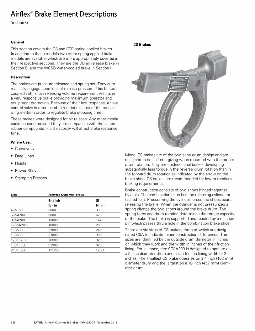
Model CS brakes are of the two shoe drum design and are designed to be self-energizing when mounted with the proper drum rotation. They are unidirectional brakes developing substantially less torque in the reverse drum rotation than in the forward drum rotation as indicated by the arrow on the brake shoe. CS brakes are recommended for low to medium braking requirements.
Brake construction consists of two shoes hinged together by a pin. The combination shoe has the releasing cylinder at-tached to it. Pressurizing the cylinder forces the shoes apart, releasing the brake. When the cylinder is not pressurized a spring clamps the two shoes around the brake drum. The spring force and drum rotation determines the torque capacity of the brake. The brake is supported and reacted by a reaction pin which passes thru a hole in the combination brake shoe.
There are six sizes of CS brakes, three of which are desig-nated CSA to indicate minor construction differences. The sizes are identified by the outside drum diameter in inches on which they work and the width in inches of their friction lining. For instance, size 9CSA200 is designed to operate on a 9 inch diameter drum and has a friction lining width of 2 inches. The smallest CS brake operates on a 4 inch (102 mm) diameter drum and the largest on a 18 inch (457 mm) diam-eter drum.
Size Forward Dynamic Torque
English SI lb . in N . m4CS150 3000 3396CSA200 6000 6789CSA200 13000 147012CSA200 18000 203015CS300 22000 249018CS300 27000 305012CTE237 28800 325018CTE300 81900 925024CTE500 111200 12600
CS Brakes
EATON Airflex® Clutches & Brakes 10M1297GP November 2012 233
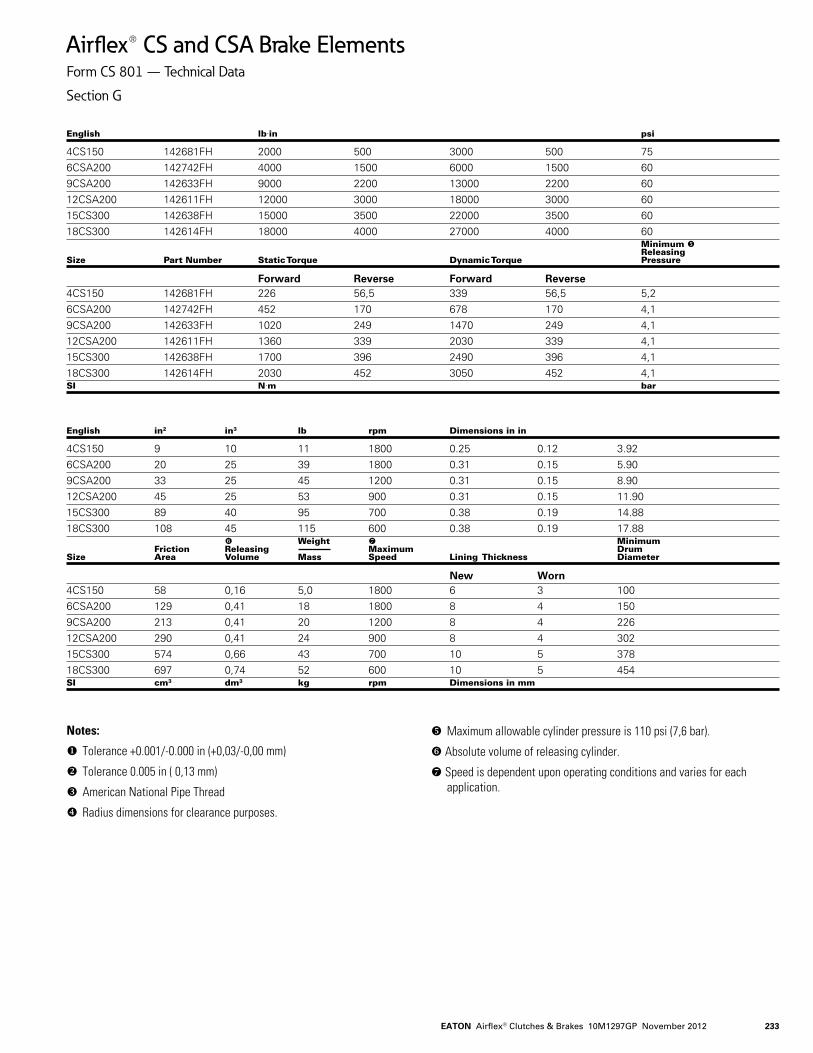
Airflex® CS and CSA Brake ElementsForm CS 801 — Technical Data
Section G
English lbin psi
4CS150 142681FH 2000 500 3000 500 75 6CSA200 142742FH 4000 1500 6000 1500 60 9CSA200 142633FH 9000 2200 13000 2200 60 12CSA200 142611FH 12000 3000 18000 3000 60 15CS300 142638FH 15000 3500 22000 3500 60 18CS300 142614FH 18000 4000 27000 4000 60 Minimum Releasing Size Part Number Static Torque Dynamic Torque Pressure
Forward Reverse Forward Reverse4CS150 142681FH 226 56,5 339 56,5 5,26CSA200 142742FH 452 170 678 170 4,19CSA200 142633FH 1020 249 1470 249 4,112CSA200 142611FH 1360 339 2030 339 4,115CS300 142638FH 1700 396 2490 396 4,118CS300 142614FH 2030 452 3050 452 4,1SI Nm bar
English in2 in3 lb rpm Dimensions in in
4CS150 9 10 11 1800 0.25 0.12 3.926CSA200 20 25 39 1800 0.31 0.15 5.909CSA200 33 25 45 1200 0.31 0.15 8.9012CSA200 45 25 53 900 0.31 0.15 11.9015CS300 89 40 95 700 0.38 0.19 14.8818CS300 108 45 115 600 0.38 0.19 17.88 Weight Minimum Friction Releasing Maximum Drum Size Area Volume Mass Speed Lining Thickness Diameter
New Worn4CS150 58 0,16 5,0 1800 6 3 1006CSA200 129 0,41 18 1800 8 4 1509CSA200 213 0,41 20 1200 8 4 22612CSA200 290 0,41 24 900 8 4 30215CS300 574 0,66 43 700 10 5 37818CS300 697 0,74 52 600 10 5 454SI cm3 dm3 kg rpm Dimensions in mm
Notes:
Tolerance +0.001/-0.000 in (+0,03/-0,00 mm)
Tolerance 0.005 in ( 0,13 mm)
American National Pipe Thread
Radius dimensions for clearance purposes.
Maximum allowable cylinder pressure is 110 psi (7,6 bar).
Absolute volume of releasing cylinder.
Speed is dependent upon operating conditions and varies for each application.
EATON Airflex® Clutches & Brakes 10M1297GP November 2012234
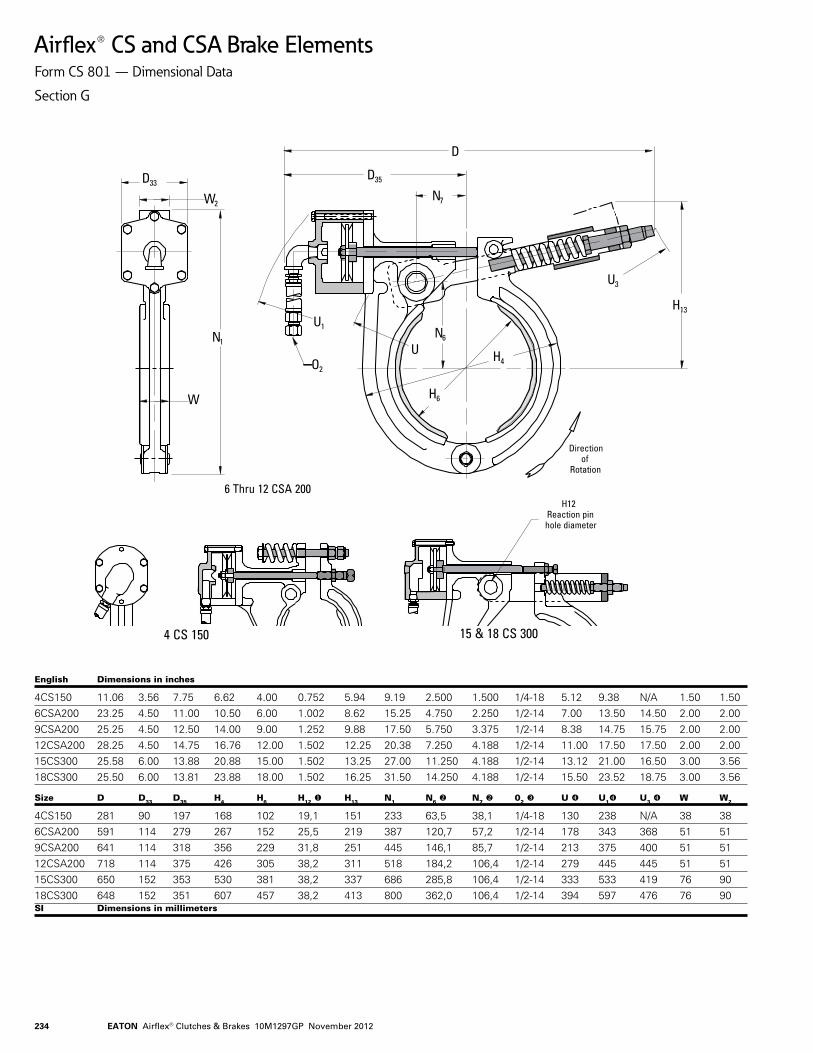
Airflex® CS and CSA Brake ElementsForm CS 801 — Dimensional Data
Section G
English Dimensions in inches
4CS150 11.06 3.56 7.75 6.62 4.00 0.752 5.94 9.19 2.500 1.500 1/4-18 5.12 9.38 N/A 1.50 1.506CSA200 23.25 4.50 11.00 10.50 6.00 1.002 8.62 15.25 4.750 2.250 1/2-14 7.00 13.50 14.50 2.00 2.009CSA200 25.25 4.50 12.50 14.00 9.00 1.252 9.88 17.50 5.750 3.375 1/2-14 8.38 14.75 15.75 2.00 2.0012CSA200 28.25 4.50 14.75 16.76 12.00 1.502 12.25 20.38 7.250 4.188 1/2-14 11.00 17.50 17.50 2.00 2.0015CS300 25.58 6.00 13.88 20.88 15.00 1.502 13.25 27.00 11.250 4.188 1/2-14 13.12 21.00 16.50 3.00 3.5618CS300 25.50 6.00 13.81 23.88 18.00 1.502 16.25 31.50 14.250 4.188 1/2-14 15.50 23.52 18.75 3.00 3.56 Size D D33 D35 H4 H6 H12 H13 N1 N6 N7 02 U U1 U3 W W2
4CS150 281 90 197 168 102 19,1 151 233 63,5 38,1 1/4-18 130 238 N/A 38 386CSA200 591 114 279 267 152 25,5 219 387 120,7 57,2 1/2-14 178 343 368 51 519CSA200 641 114 318 356 229 31,8 251 445 146,1 85,7 1/2-14 213 375 400 51 5112CSA200 718 114 375 426 305 38,2 311 518 184,2 106,4 1/2-14 279 445 445 51 5115CS300 650 152 353 530 381 38,2 337 686 285,8 106,4 1/2-14 333 533 419 76 9018CS300 648 152 351 607 457 38,2 413 800 362,0 106,4 1/2-14 394 597 476 76 90 SI Dimensions in millimeters
D33
W2
N1
W
D35
N7
D
U1
O2
U3
N6
H6
H4U
H13
H12Reaction pinhole diameter
15 & 18 CS 3004 CS 150
Directionof
Rotation
6 Thru 12 CSA 200
EATON Airflex® Clutches & Brakes 10M1297GP November 2012 235
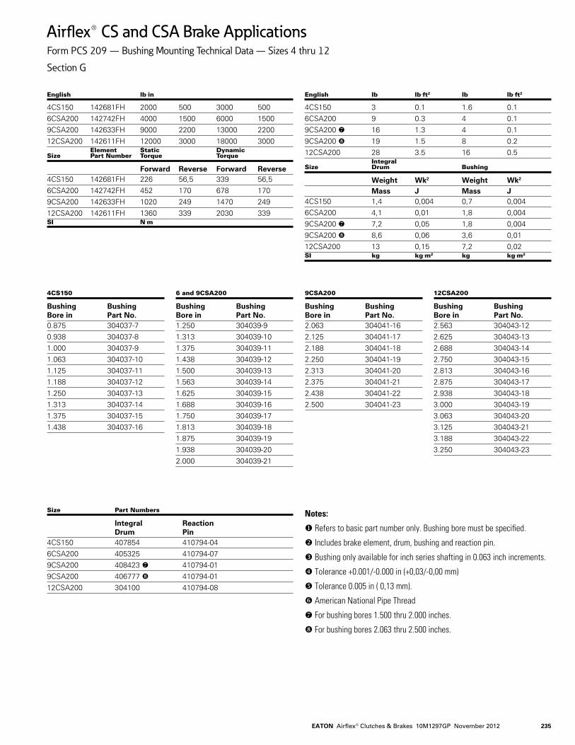
Airflex® CS and CSA Brake ApplicationsForm PCS 209 — Bushing Mounting Technical Data — Sizes 4 thru 12
Section G
English lbin
4CS150 142681FH 2000 500 3000 5006CSA200 142742FH 4000 1500 6000 15009CSA200 142633FH 9000 2200 13000 220012CSA200 142611FH 12000 3000 18000 3000 Element Static Dynamic Size Part Number Torque Torque
Forward Reverse Forward Reverse4CS150 142681FH 226 56,5 339 56,56CSA200 142742FH 452 170 678 1709CSA200 142633FH 1020 249 1470 24912CSA200 142611FH 1360 339 2030 339SI Nm
English lb lbft2 lb lbft2
4CS150 3 0.1 1.6 0.16CSA200 9 0.3 4 0.19CSA200 16 1.3 4 0.19CSA200 19 1.5 8 0.212CSA200 28 3.5 16 0.5 Integral Size Drum Bushing
Weight Wk2 Weight Wk2
Mass J Mass J4CS150 1,4 0,004 0,7 0,0046CSA200 4,1 0,01 1,8 0,0049CSA200 7,2 0,05 1,8 0,0049CSA200 8,6 0,06 3,6 0,0112CSA200 13 0,15 7,2 0,02SI kg kgm2 kg kgm2
4CS150
Bushing Bushing Bore in Part No.0.875 304037-70.938 304037-81.000 304037-91.063 304037-101.125 304037-111.188 304037-121.250 304037-131.313 304037-141.375 304037-151.438 304037-16
Size Part Numbers
Integral Reaction Drum Pin4CS150 407854 410794-046CSA200 405325 410794-079CSA200 408423 410794-019CSA200 406777 410794-0112CSA200 304100 410794-08
6 and 9CSA200
Bushing Bushing Bore in Part No.1.250 304039-91.313 304039-101.375 304039-111.438 304039-121.500 304039-131.563 304039-141.625 304039-151.688 304039-161.750 304039-171.813 304039-181.875 304039-191.938 304039-202.000 304039-21
9CSA200
Bushing Bushing Bore in Part No.2.063 304041-162.125 304041-172.188 304041-182.250 304041-192.313 304041-202.375 304041-212.438 304041-222.500 304041-23
12CSA200
Bushing Bushing Bore in Part No.2.563 304043-122.625 304043-132.688 304043-142.750 304043-152.813 304043-162.875 304043-172.938 304043-183.000 304043-193.063 304043-203.125 304043-213.188 304043-223.250 304043-23
Notes:
Refers to basic part number only. Bushing bore must be specified.
Includes brake element, drum, bushing and reaction pin.
Bushing only available for inch series shafting in 0.063 inch increments.
Tolerance +0.001/-0.000 in (+0,03/-0,00 mm)
Tolerance 0.005 in ( 0,13 mm).
American National Pipe Thread
For bushing bores 1.500 thru 2.000 inches.
For bushing bores 2.063 thru 2.500 inches.
EATON Airflex® Clutches & Brakes 10M1297GP November 2012236
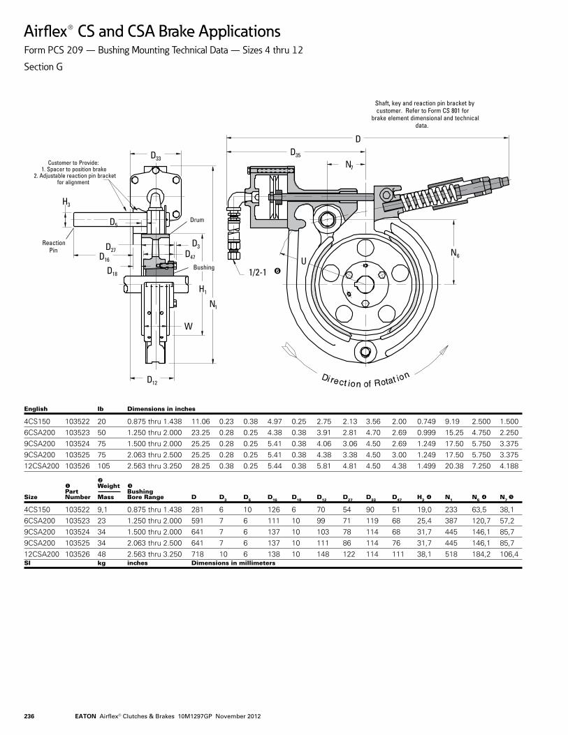
Airflex® CS and CSA Brake ApplicationsForm PCS 209 — Bushing Mounting Technical Data — Sizes 4 thru 12
Section G
Customer to Provide:1. Spacer to position brake
2. Adjustable reaction pin bracketfor alignment
D16
D27
H3
ReactionPin
Drum
Bushing
D3D47
H1
N1
D18
W
D33
D5
D12
N6
1/2-1
Shaft, key and reaction pin bracket bycustomer. Refer to Form CS 801 for
brake element dimensional and technicaldata.
U
D35
N7
D
English lb Dimensions in inches
4CS150 103522 20 0.875 thru 1.438 11.06 0.23 0.38 4.97 0.25 2.75 2.13 3.56 2.00 0.749 9.19 2.500 1.5006CSA200 103523 50 1.250 thru 2.000 23.25 0.28 0.25 4.38 0.38 3.91 2.81 4.70 2.69 0.999 15.25 4.750 2.2509CSA200 103524 75 1.500 thru 2.000 25.25 0.28 0.25 5.41 0.38 4.06 3.06 4.50 2.69 1.249 17.50 5.750 3.3759CSA200 103525 75 2.063 thru 2.500 25.25 0.28 0.25 5.41 0.38 4.38 3.38 4.50 3.00 1.249 17.50 5.750 3.37512CSA200 103526 105 2.563 thru 3.250 28.25 0.38 0.25 5.44 0.38 5.81 4.81 4.50 4.38 1.499 20.38 7.250 4.188 Weight Part Bushing Size Number Mass Bore Range D D3 D5 D16 D18 D12 D27 D33 D47 H3 N1 N6 N7
4CS150 103522 9,1 0.875 thru 1.438 281 6 10 126 6 70 54 90 51 19,0 233 63,5 38,16CSA200 103523 23 1.250 thru 2.000 591 7 6 111 10 99 71 119 68 25,4 387 120,7 57,29CSA200 103524 34 1.500 thru 2.000 641 7 6 137 10 103 78 114 68 31,7 445 146,1 85,79CSA200 103525 34 2.063 thru 2.500 641 7 6 137 10 111 86 114 76 31,7 445 146,1 85,712CSA200 103526 48 2.563 thru 3.250 718 10 6 138 10 148 122 114 111 38,1 518 184,2 106,4SI kg inches Dimensions in millimeters
EATON Airflex® Clutches & Brakes 10M1297GP November 2012 237
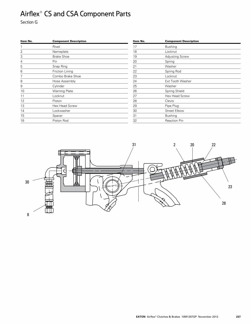
Airflex® CS and CSA Component PartsSection G
Item No. Component Description
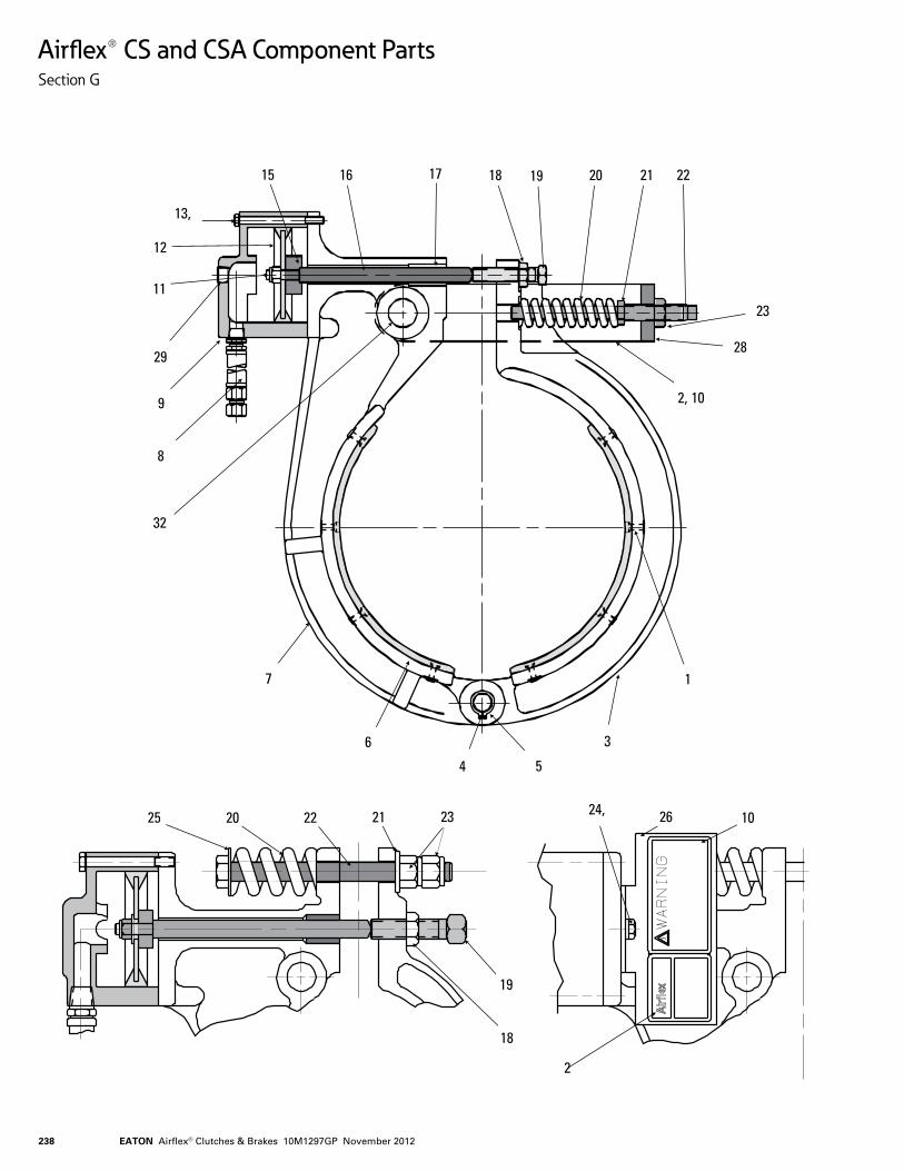
1 Rivet2 Nameplate3 Brake Shoe4 Pin5 Snap Ring6 Friction Lining7 Combo Brake Shoe8 Hose Assembly9 Cylinder10 Warning Plate 11 Locknut12 Piston13 Hex Head Screw14 Lockwasher15 Spacer16 Piston Rod
Item No. Component Description
17 Bushing18 Locknut19 Adjusting Screw20 Spring21 Washer22 Spring Rod23 Locknut24 Ext Tooth Washer25 Washer26 Spring Shield27 Hex Head Screw28 Clevis29 Pipe Plug30 Street Elbow31 Bushing32 Reaction Pin
20
23
31 2 22
30
8
28
EATON Airflex® Clutches & Brakes 10M1297GP November 2012238
Airflex® CS and CSA Component PartsSection G
23
28
2, 10
3
54
11
16
12
13,
1
6
7
8
29
9
1715 22212018 19
32
2
20 102624,25
18
19
2122 23
EATON Airflex® Clutches & Brakes 10M1297GP November 2012 239
Airflex® Brake Element DescriptionsSection G
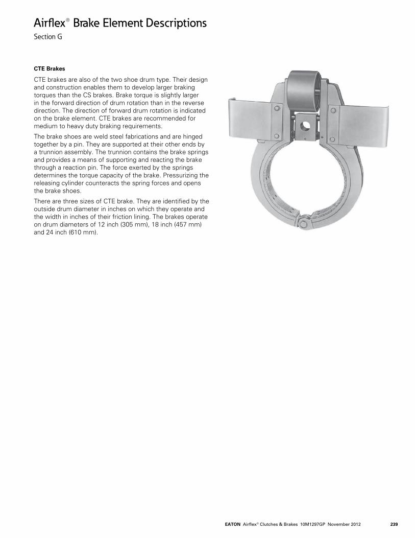
CTE Brakes
CTE brakes are also of the two shoe drum type. Their design and construction enables them to develop larger braking torques than the CS brakes. Brake torque is slightly larger in the forward direction of drum rotation than in the reverse direction. The direction of forward drum rotation is indicated on the brake element. CTE brakes are recommended for medium to heavy duty braking requirements.
The brake shoes are weld steel fabrications and are hinged together by a pin. They are supported at their other ends by a trunnion assembly. The trunnion contains the brake springs and provides a means of supporting and reacting the brake through a reaction pin. The force exerted by the springs determines the torque capacity of the brake. Pressurizing the releasing cylinder counteracts the spring forces and opens the brake shoes.
There are three sizes of CTE brake. They are identified by the outside drum diameter in inches on which they operate and the width in inches of their friction lining. The brakes operate on drum diameters of 12 inch (305 mm), 18 inch (457 mm) and 24 inch (610 mm).
EATON Airflex® Clutches & Brakes 10M1297GP November 2012240
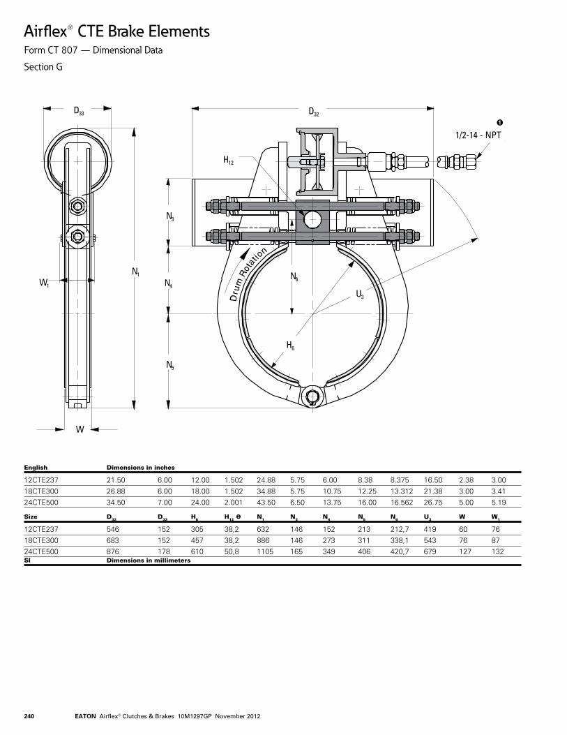
Airflex® CTE Brake ElementsForm CT 807 — Dimensional Data
Section G
D33
W1
N1
W
D32
N3
N4
N5
H6
N6
U3
H12
1/2-14 - NPT
English Dimensions in inches
12CTE237 21.50 6.00 12.00 1.502 24.88 5.75 6.00 8.38 8.375 16.50 2.38 3.0018CTE300 26.88 6.00 18.00 1.502 34.88 5.75 10.75 12.25 13.312 21.38 3.00 3.4124CTE500 34.50 7.00 24.00 2.001 43.50 6.50 13.75 16.00 16.562 26.75 5.00 5.19 Size D32 D33 H6 H12 N1 N3 N4 N5 N6 U3 W W1
12CTE237 546 152 305 38,2 632 146 152 213 212,7 419 60 7618CTE300 683 152 457 38,2 886 146 273 311 338,1 543 76 8724CTE500 876 178 610 50,8 1105 165 349 406 420,7 679 127 132SI Dimensions in millimeters
EATON Airflex® Clutches & Brakes 10M1297GP November 2012 241
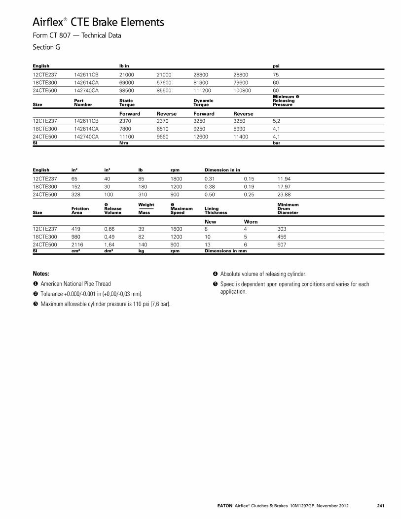
Airflex® CTE Brake ElementsForm CT 807 — Technical Data
Section G
English lbin psi
12CTE237 142611CB 21000 21000 28800 28800 7518CTE300 142614CA 69000 57600 81900 79600 6024CTE500 142740CA 98500 85500 111200 100800 60 Minimum Part Static Dynamic Releasing Size Number Torque Torque Pressure
Forward Reverse Forward Reverse12CTE237 142611CB 2370 2370 3250 3250 5,218CTE300 142614CA 7800 6510 9250 8990 4,124CTE500 142740CA 11100 9660 12600 11400 4,1SI Nm bar
English in2 in3 lb rpm Dimension in in
12CTE237 65 40 85 1800 0.31 0.15 11.9418CTE300 152 30 180 1200 0.38 0.19 17.9724CTE500 328 100 310 900 0.50 0.25 23.88 Weight Minimum Friction Release Maximum Lining Drum Size Area Volume Mass Speed Thickness Diameter
New Worn12CTE237 419 0,66 39 1800 8 4 30318CTE300 980 0,49 82 1200 10 5 45624CTE500 2116 1,64 140 900 13 6 607SI cm2 dm3 kg rpm Dimensions in mm
Notes:
American National Pipe Thread
Tolerance +0.000/-0.001 in (+0,00/-0,03 mm).
Maximum allowable cylinder pressure is 110 psi (7,6 bar).
Absolute volume of releasing cylinder.
Speed is dependent upon operating conditions and varies for each application.
EATON Airflex® Clutches & Brakes 10M1297GP November 2012242
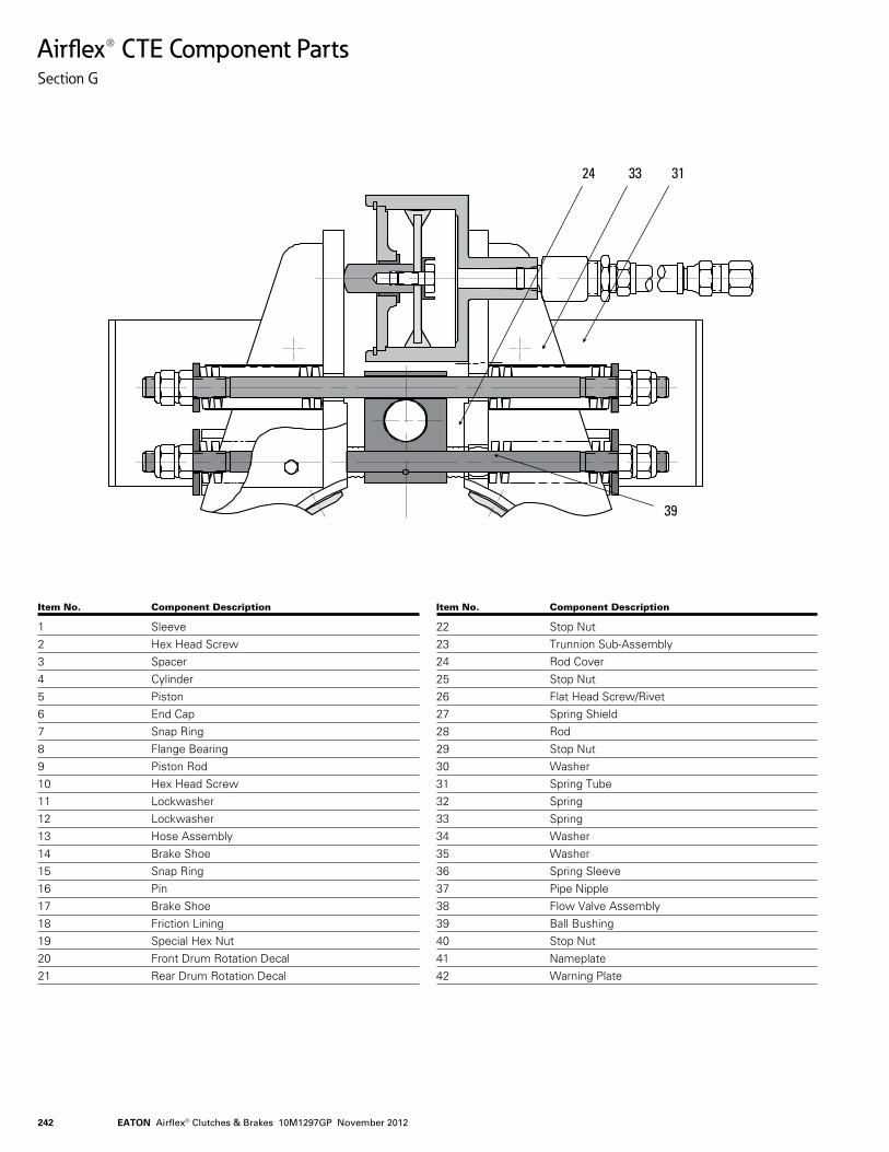
Airflex® CTE Component PartsSection G
Item No. Component Description
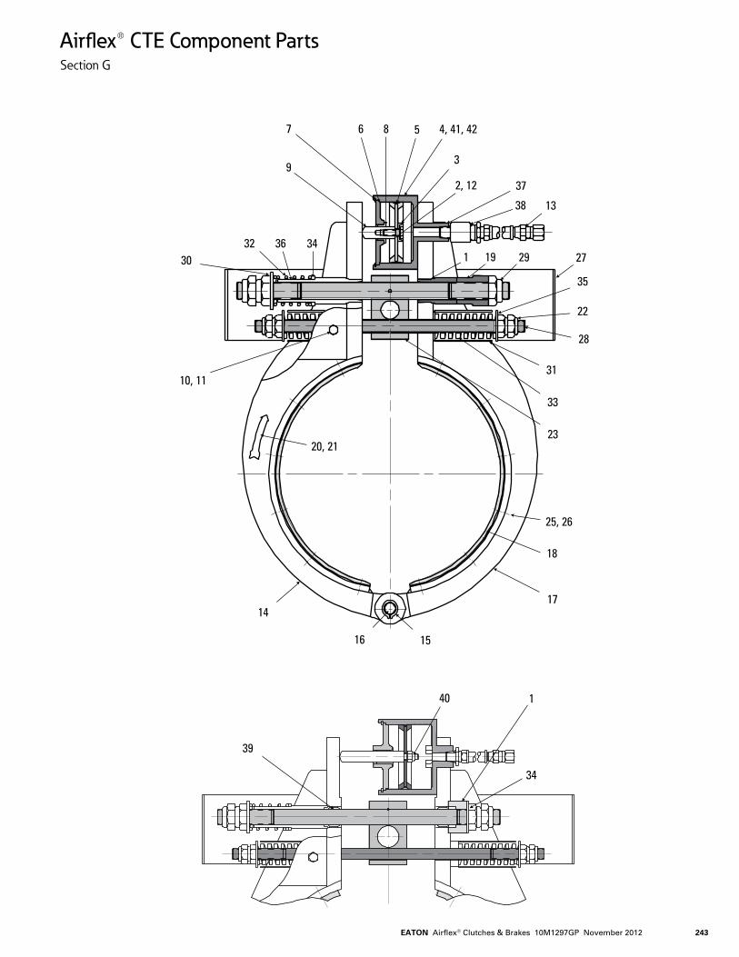
1 Sleeve2 Hex Head Screw3 Spacer4 Cylinder5 Piston6 End Cap7 Snap Ring8 Flange Bearing9 Piston Rod10 Hex Head Screw11 Lockwasher12 Lockwasher13 Hose Assembly14 Brake Shoe15 Snap Ring16 Pin17 Brake Shoe18 Friction Lining19 Special Hex Nut20 Front Drum Rotation Decal21 Rear Drum Rotation Decal
Item No. Component Description
22 Stop Nut23 Trunnion Sub-Assembly24 Rod Cover25 Stop Nut26 Flat Head Screw/Rivet27 Spring Shield28 Rod29 Stop Nut30 Washer31 Spring Tube32 Spring33 Spring34 Washer35 Washer36 Spring Sleeve37 Pipe Nipple38 Flow Valve Assembly39 Ball Bushing40 Stop Nut41 Nameplate42 Warning Plate
39
313324
EATON Airflex® Clutches & Brakes 10M1297GP November 2012 243
Airflex® CTE Component PartsSection G
7
9
34363230
10, 11
20, 21
15
17
18
25, 26
28
33
31
23
22
35
2729191
372, 12
3
4, 41, 42
38
586
13
16
14
39
40 1
34
EATON Airflex® Clutches & Brakes 10M1297GP November 2012244
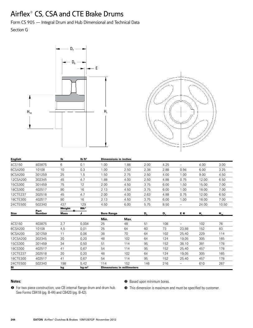
Airflex® CS, CSA and CTE Brake DrumsForm CS 905 — Integral Drum and Hub Dimensional and Technical Data
Section G
D7
E
H1H14
D6
English lb lbft2 Dimensions in inches
4CS150 403875 6 0.1 1.00 1.88 2.00 4.25 – 4.00 3.006CSA200 10108 10 0.3 1.00 2.50 2.38 2.88 0.94 6.00 3.259CSA200 301259 25 1.5 1.50 2.75 2.50 4.00 1.00 9.00 4.5012CSA200 302345 45 4.7 1.88 4.00 2.50 4.88 0.75 12.00 6.5015CS300 301459 75 12 2.00 4.50 3.75 6.00 1.50 15.00 7.0018CS300 402517 90 16 2.13 4.50 3.75 6.00 1.00 18.00 7.0012CTE237 302518 45 4.7 2.00 4.00 2.63 4.88 0.75 12.00 6.5018CTE300 402517 90 16 2.13 4.50 3.75 6.00 1.00 18.00 7.0024CTE500 502340 437 129 4.50 6.00 5.75 8.50 – 24.00 10.50 Weight Wk2 Part Size Number Mass J Bore Range D6 D7 E H1 H14
Min. Max.4CS150 403875 2,7 0,004 25 48 51 108 – 102 766CSA200 10108 4,5 0,01 25 64 60 73 23,88 152 83 9CSA200 301259 11 0,06 38 70 64 102 25,40 229 114 12CSA200 302345 20 0,20 48 102 64 124 19,05 305 165 15CS300 301459 34 0,50 51 114 95 152 38,10 381 178 18CS300 402517 41 0,67 54 114 95 152 25,40 457 178 12CTE237 302518 20 0,20 48 102 64 124 19,05 305 165 18CTE300 402517 41 0,67 54 114 95 152 25,40 457 178 24CTE500 502340 198 5,42 114 152 146 216 – 610 267 SI kg kgm2 Dimensions in millimeters
Notes:
For two piece construction, use CB internal flange drum and drum hub. See Forms CB418 (pg. B-44) and CB420 (pg. B-42).
Based upon minimum bores.
This dimension is maximum and must be specified by customer.
EATON Airflex® Clutches & Brakes 10M1297GP November 2012 245
Airflex® Selection ProcedureBrake Torque and Thermal Capacities
Section G
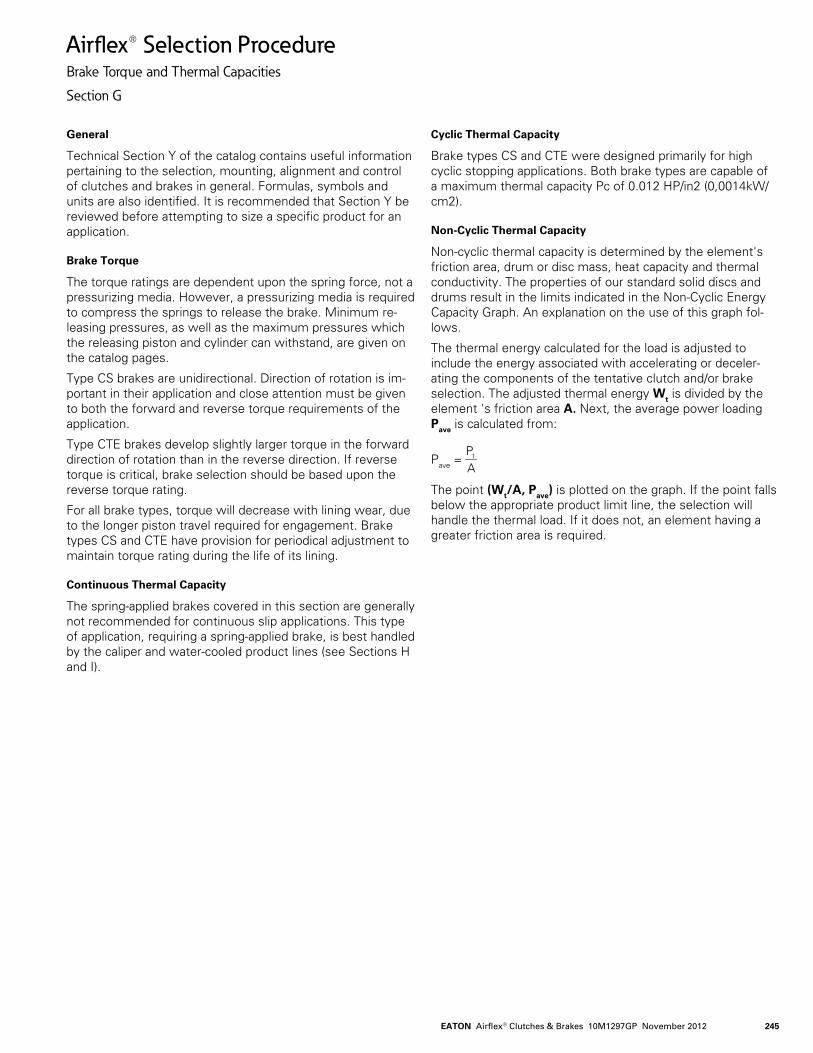
General
Technical Section Y of the catalog contains useful information pertaining to the selection, mounting, alignment and control of clutches and brakes in general. Formulas, symbols and units are also identified. It is recommended that Section Y be reviewed before attempting to size a specific product for an application.
Brake Torque
The torque ratings are dependent upon the spring force, not a pressurizing media. However, a pressurizing media is required to compress the springs to release the brake. Minimum re-leasing pressures, as well as the maximum pressures which the releasing piston and cylinder can withstand, are given on the catalog pages.
Type CS brakes are unidirectional. Direction of rotation is im-portant in their application and close attention must be given to both the forward and reverse torque requirements of the application.
Type CTE brakes develop slightly larger torque in the forward direction of rotation than in the reverse direction. If reverse torque is critical, brake selection should be based upon the reverse torque rating.
For all brake types, torque will decrease with lining wear, due to the longer piston travel required for engagement. Brake types CS and CTE have provision for periodical adjustment to maintain torque rating during the life of its lining.
Continuous Thermal Capacity
The spring-applied brakes covered in this section are generally not recommended for continuous slip applications. This type of application, requiring a spring-applied brake, is best handled by the caliper and water-cooled product lines (see Sections H and I).
Cyclic Thermal Capacity
Brake types CS and CTE were designed primarily for high cyclic stopping applications. Both brake types are capable of a maximum thermal capacity Pc of 0.012 HP/in2 (0,0014kW/cm2).
Non-Cyclic Thermal Capacity
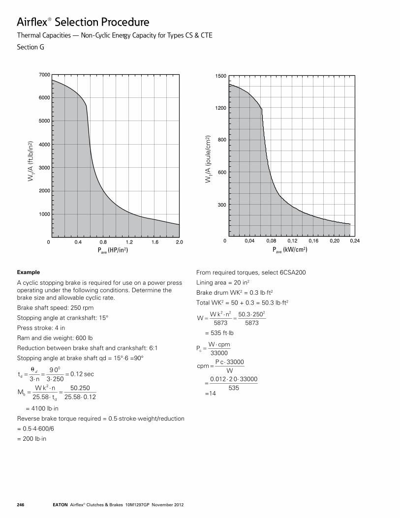
Non-cyclic thermal capacity is determined by the element's friction area, drum or disc mass, heat capacity and thermal conductivity. The properties of our standard solid discs and drums result in the limits indicated in the Non-Cyclic Energy Capacity Graph. An explanation on the use of this graph fol-lows.
The thermal energy calculated for the load is adjusted to include the energy associated with accelerating or deceler-ating the components of the tentative clutch and/or brake selection. The adjusted thermal energy Wt is divided by the element 's friction area A. Next, the average power loading Pave is calculated from:
Pave = The point (Wt/A, Pave) is plotted on the graph. If the point falls below the appropriate product limit line, the selection will handle the thermal load. If it does not, an element having a greater friction area is required.
APt
EATON Airflex® Clutches & Brakes 10M1297GP November 2012246
Airflex® Selection ProcedureThermal Capacities — Non-Cyclic Energy Capacity for Types CS & CTE
Section G
Example
A cyclic stopping brake is required for use on a power press operating under the following conditions. Determine the brake size and allowable cyclic rate.
Brake shaft speed: 250 rpm
Stopping angle at crankshaft: 15°
Press stroke: 4 in
Ram and die weight: 600 lb
Reduction between brake shaft and crankshaft: 6:1
Stopping angle at brake shaft qd = 15°·6 =90°
= 4100 lb·in
Reverse brake torque required = 0.5·stroke·weight/reduction
= 0.5·4·600/6
= 200 lb·in
From required torques, select 6CSA200
Lining area = 20 in2
Brake drum WK2 = 0.3 lb·ft2
Total WK2 = 50 + 0.3 = 50.3 lb·ft2
= 535 ft·lb
=140.1225.5850.250
t 25.58nk W
M
sec 0.1225030 9
n3 t
d
2
b
0
d
⋅=
⋅⋅
=
=⋅
=⋅
= d0
587325050.3
5873nk W
W 222 ⋅
=⋅
=
33000cpm W
Pc
⋅=
W33000 c P
cpm⋅
=
535330000 2 0.012
⋅⋅
=
W1/A(ft •lb/in
2 )
Pave (HP/in2)
W1/A(jo
ule/cm
2 )
Pave (kW/cm2)