Embed Size (px)
Citation preview
REPORT No. 446
AIRFOIL SECTION CHARACTERISTICS AS AFFECTED BY PROTUBERANCES
By EASTMAN N. JACOBS
SUMMARY
The drag and interference causedfrom tb surface of an airfoil hum been
by protuberantdeterminedin the
‘N. A. O. A_. varhkkity wind hmt-el d a ReynokhNumbw oj approximately3,100,000. % e~eci8oj vari-atimw of thefore-and-afi podiun, heighi, and shupe ojthe protuberance were meiww.redby determining how t)kairfoil 8ecti0ncharacterhticxwere ajected by the addiiionof th variom @otu&ram @5n4i?i~ W th &wespan of the airjoi.t. T/i-5re4ult8 provide fundamentaldala on which to base theprediction of the e~eri%of actual8h0rt-8panprotuberanztx. The data may &o be appliedto tlu de-signof air brakes and 8poiLer8.
INTRODU~ON
The ideal airplane, aerodynamically, may be con-sidered as one having only the drag due b skin frictionand the minimum induced drag associated with its lift.Prof. B. M. Jones in England has shown that actualairplanes fall far short of such an ideal. Interferenceeffects, it seems, must be blamed for a considerable partof the energy wasted in producing the turbulencemsocirkd with the comparatively large drag of actualairplanes.
The National Advisory Committee for Aeronauticshas planned a series of investigations dealing with thesubject of aerodynamic interference. The investiga-tions will, it is hoped, lead to the discovery of the causeof the serious adverse effects and will provide data thatmay be applied to the solution of practical problems ofdesign. An examination of presentiay airplanes, bothmilitary and commercial, hss led to the belief that aconsiderable part of the adveme bt.erference arisesfrom small projecting objects, such as fittings, tubes,wires, rivet heads, lap joints, butt straps, filler caps,inspection plates, and many other projections from themain surfaces that may be considered together as pro-tubercumea. A systematic investigation of protuber-ances differently formed and variously located shouldindicate the relative msgnitude of such effects and alsoshow the effect of disturbing the flow in the boundarylayer about otherwise streamline bodies.
Some mrly investigations of boundary-interferenceeffects were originated by Prandtl at G6ttingen in 1914
to study the effects of a small ring protruding from thesurface of a sphere. Large negative, or favorable,interference effects were observed at certain values ofthe Reynolds Number because the turbulence produmdby the protuberance changed the character of theboundary layer so aa to delay the separation of the flowfrom the surface, thus producing a smaller turbulentwake and a smaller drag. Similar experiments havemore recently been performed by Ower in Englandwith streamline bodies. (Reference 1.) At low valuesof the Reynolds Numb6r, when the flow in the bound-ary layer of the body is to a considerable extentlaminar, protuberances from the forward portions ofthe body cause a transition horn the laminsr to theturbulent state of flow in the boundary layer with aresulting increase of drag. This effect is not of greatpractical signifkance, however, because the flow in theboundaq layer of full-scale bodies is probably, in anyevent to a large extent, of the turbulent type. It isadvisable, therefore, to make im-estimations involvingboundary-interference effects at large vah.ws of theReynolds Number if they are to be of the greatestpractical value.
Tests have been made in the variabl~density windtunnel at large values of the Reynolds Number todetermine the effects of protuberance from the surfaceof a streamlined body of revolution. The results havenot yet been published. The present report deals withanother phsse of the investigation; that is, the effectson airfoil wction characteristics of protuberances ex-tending along the entire span from the airfoil surface.A succeeding report will consider the effects on wingcharacteristics of protubersmces extending ordy overportions of the wing span. The tests with which thepresent report deals were made in the N. A. C. A.variabledensity wind tunnel during Mar&, 1932.
The N. A. C. A. 0012 airfoil section was employedthroughout the investigation and the dynamic scale ofthe tests was maintained approximately the samethroughout (Reynolds Number 3,100,000). The effectsof variations of the position, size, and shape of the pro-tuberance were measured by detenninin g how the air-foil section characteristics were aileetad by the additionof the various protuberances.
109
https://ntrs.nasa.gov/search.jsp?R=19930091520 2020-04-27T17:39:31+00:00Z

110 REPORT NATIONAL ADVTSORY
TESTS
The N. A. C. A variabledensity tunnel and themethods employed for airfoil testing in the tunnel aredescribed in detail in reference 2. These tests weremade in the usual way, measuring the lift, drag, andpitching moments on a 5 by 30 inch duralumin airfoilmounted in the air stream so that the angle of attackcould be varied. The model mounting difEered in onerespect from that described in reference 2. Insteadof using a sting attached to the lower surface of theairfoil as part of the airfoil support, a special st@ wasemployed that was attached near the &ding edge ofthe airfoil. As the airfoil has symmetrical sections, itwas thus possible to make the airfoil and sting as-sembly symmetrical about the plane of the airfoilchords.
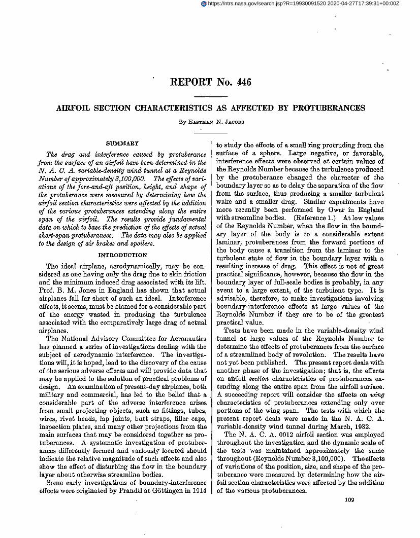
A section of the airfoil employed, the N. A. C. A.0012 (reference 3), is shown in Figure 1. The pro-tuberances were placed in the slots shown, the posi-
,--00125cpm tubermce in 0.15 cposifim
Leading edge po=”fion. Sfofions & wdinaks in Z chord
FIGURE I.-N. A. C.A. 0)12 dlfOil nhowims Protnbemmm
tions being: Directly at the leading edge; 5 per centof the chord behind the leading edge; 15 per cent(approximately the front spar position); 30 per cent(maximum ordinate position); and 65 per cent (ap-proximately the rear spar position). The protuber-ances were placed only on “the upper side of the sym-metrical airfoil, but the effect of each on the lowersurface was determined by testing the airfoil throughthe negative angle-of-attack range.
The protuberance consisted of a strip of sheet du-rahunin havi.qg the desired height placed in one of theslots indicated in I&me 1 in such a way as to extendalong the entire span of the model. The form that willbe referred to as the faired protuberance was produced,as indicated in Figure 1, by forming over the protuber-ance a plaster*f-Paris fairing the cross section of whichapproximated a small half airfoil section on the surfaceof the main airfoil. The slots in the airfoil when not inuse were fled with duralumin strips carefully filed tothe surface apd polished to present a continuous smoothsurface. The protuberance was used in only one slotat a time, start@ with the highest protuberance0.0125c, and then reducing the height consecutively to0.0050c, 0.0020c, and in some cases to O.OO1OCand0.0004c, by filing off the top of the projecting strip.
00~ FOB AEBONAUTIOS
The characteristics of the airfoil without protuber-ances-that is, with all slots iilled-were measuredtwica during the progress of the investigation as acheck on the consistency of the results.
For comparison with the results obtained at nega-tive angles of attack, average curves for the negative-angle runs on the plain airfoil have been used. Thesediffer slightly from the corresponding positive-anglecurves because of asymmetrical support interference.When the protuberance was in the leading-edge posi-tion the tests were made at both positive and negativeangles of attack, but average curves have bedn usedto present the results. Thus the various curves pre-senting the results for the plain airfoil do not agreeexactly. Furthermore, they should not be expected toaggee with other tests of the same airfoil, because thetare-drag correction applied throughout this investiga-tion did not allow for the lower drag of the special air-foil sting employed.
RESULTS AND DISCUSSION
The results are presented by means of curves of thelift coefficient CL, pro filedrag coefficient C~O,momentcoefficient about a point one-qumter of the chord be-hind the leading edge Cm,, and the angle of attack foriniinite aspect ratio aO. The results are thus presentedas airfoil section characteristics. The most importantresults, those corresponding to the various heights rmdpositions of the protubermce, are presented in Figures2 to 10. Attention should be here called to the fact,however, that the characteristics thus presented shouldnot be used with precise strip method calculations asthough they were true iniinite-aspecl+ratio character-istics, but should be considered as average sectioncharacteristics deduced from the test data by themethods described in reference 2. Differences be-tween these section characteristics and the true onesmay probably be neglected as long as all the sections ofthe rectangular wing that was tested were operatingat effective angles of attack +rithin the range of rLp-proximately normal lift curve slope. Their use is alsopartly justified by the fact that appro.simately correctresults for a f&span protuberate on a wing of nor-mal aspect ratio are obtained from them when thesimple aspect-ratio corrections (reference 2) areRpplied.
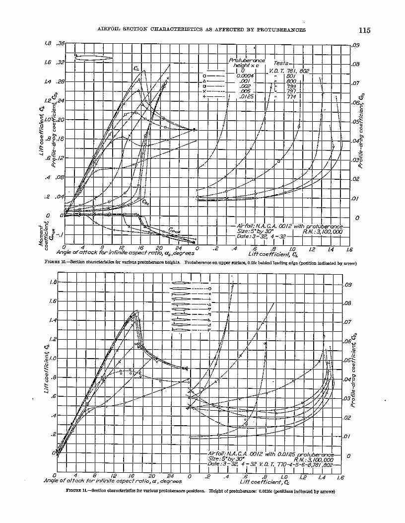
Protuberance position.-The results for the largestprotuberance (0.0125c) in the various positions on theairfoil surface are. shown in Figure 11. Considering6rst the effects of the protuberance on the lift at lowangles of attack, it will be seen that the effect of theprotuberamx is to decrease the lift slightly for nllupper-surface positions and to increase it slightly forRU lower?yrfac~ positions. As regards the lift athigher angles of attack and the maximum value of thelift, the protuberances on the lower surface have littleeffect, whereas the adverse effect of those on the upper

AIRFOIL SEOTION CHAIL4CTEHSTIOS AS AIWEOTJ?ADBY PEtOTUBFiR&NOES 111
FIf3UEE 2-9ectlon rimracteristiu for various protubmanra helgbk Pmtnbmum on ImrUng edge @ition indicated by arrow)
1.8 .36’ .09
1.6 .32 .08
1.4 .28 .07
0
1.2f24be
.06%.~~ $ $>. :$
-.
$ /.0$.20.+!
.. .05->
$.%. 8 8
g .8g’.l6 .04 ~
k~~
..
4 .6Q 12
~
$’.03%
&
.4 ,08 .02
.2 .04 .01
00 0.
.&I
?
$ %_.,.E.C5
g; o ~ ~ ,2 ,8 Z. 24 0 .2 ~ .6 .8 Lo ~ ,4‘v
Angle of affo& for infihite aspect rafio, CYO,degrees16
Lift coefficient, CL
~OUBE 3.-%dI0II dI.81WQk19tk3h VIU%3USp~ height% Protnbmmra on 10TW snrfiq 0.05c behtul ledlng edge @dion indbtal by arrow)

112 REPOET NATIONAL ADVISOBY CO~ FOR AERONAUTICS
.
FIGURES.-mmon -Ckri6tfcs for Vaiiom PrOtabmma halglk Protnterarm on lower #mfacej CL30CMind leadlng M@ @siUon lndkated by arrow)

AIRFOIL SEOTION CI13AR40!LWEQ3TIC43AS AEFEOTED BY PIiOTUBEMNOES 113
FIOIJF!E @.-&ctlon olmmoterbtica for VMOIM pmtnkarrm hdgbk Pmtukance on lower mrfaq O.O& beldnd kadlng CS+3EE@ftirm lndidod by arrow)
1.8 .36 .09
/.6 .32 .08
/.4 .28 .07
&Lz&’4
t? ,8 “04.&l
, gtog.ad
.os~%~:_
~b
Fh3ww 7.-&d0n chraddd mfor varfous protnkomnm heights Protubamnco on UPW mrface 116.Zxbehfnd kadlng edge (pcaitiorr Lndfcatal by arrow)

EEFOILT NATIONAL ADVISORY COMMDTEE FOB AERONAUTICS114
1.8
1.6
L4
FIGURE S.-.%tlon cimracterktks for verieos protnkanm hdghta. Protukm.rm on nPIMT snr’faq 0.31 behind leading edge @Yklon Indkatal by arrow)
.63.12 .UJ o
4 k
.4 .08 .02
.2 .04 .011 @ 1 I 1 1 I T I f I
&#q-iGJ l“til II!!!!!!!,I <% I I I I I I I I I ‘ .4+w7: N./
— I=&g2. I Size:5_”by
.Angle of shack &h%% as&f roi;o, do ,degrees .Liff we fficienf, CL
Fmwmk-ktlon cbnracia+stb for-a-iom @mbemnm helghta. Pmtnkarmo on upper sorfaq @J& behind lredlng wige @dtlen Indhmtcd by arrow)
AIRFOIL SECTION CHAR4CTERISTICIS AS AFFEOTED BY PBOTUEEBANOES 115
~amE Ia-$ectlon obmacterktica for varions protnberanm heights Protulxmnca on UPW .mrfac% (M!& behind Ieadlng edge Qx8ition indicated by arrow)
1.
1.
1.
1.=*
.s-J
AI
.
Fmmm 11.-$ect[on cbaracimktks far vorfom protukance LK8Mona HeightOf PIotnbmanc& 0.012& @&iona Indicated by arrows)
,
,
116 BEPOBT NATIONAL ADVISOBY
surface becomes increasingly serious as the protuber-ance approaches a point near the leading edge.
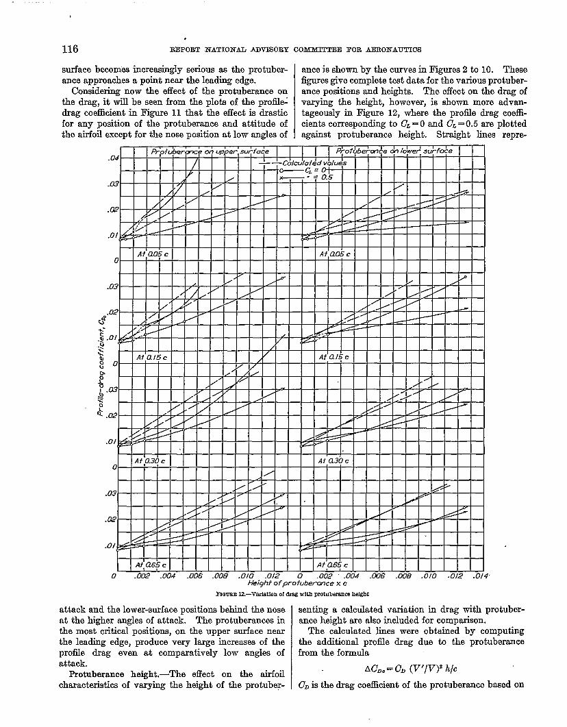
Considering now the effect of the protuberance onthe drag, it will be seen fxom the plots of the proflle~drag coeilicient in Figure 11 that the effect is drasticfor any position of the protuberant and attitude ofthe airfoil except for the nose position at low angles of
CIOMMJTIEE BOB AERONAUTICS
ante is shown by the curves in Figures 2 to 10. Themfigures give completa teat data for the various protuber-ance positions and heights. The effect on the drag ofvarying the height, however, is shown more advan-tageously in Figure 12, where the proil.le drag coeffi-cients corresponding to CL= O and CL= 0.5 are plottedagainst protuberance height. Straight lines repre-
0 .W .004 .006 .006 .010 .012 0 .002 .004 .C06 .W8 .010 .012 .014’Akight of pro tubemce x c
FIQUBEU—Variation Of (IIW with P@IIb0r8nw hel@t
attack and the lower-surface positions behind the noseat the higher angles of attack. The protuberances inthe most critical positions, on the upper surface nearthe leading edge, produce very large increases of theprofile drag even at comparatively low angles ofattack.
Protuberance height.-’l%e effect on the fioilcharactwistics of varying the height of the protubey-
senting a calcdated variation in drag with protuber-ance height are also included for comparison.
The calculated lines were obtained by computingthe additional profile drag due to the protuberancefrom the formula
AC~O= CD (V’/V)z h/c
CDis the drag coefficient of the protuberance baaed on
,.-AIRFOIL SEOTION OHAEACTEEUSTICS M AFFECTED BY PROTUBER4NOES ll”i
its frontal area. Weiselsberger (reference 4) giws thedrag coefficient for flat pldes of very large aspect ratioas approximately 2. The value 2 was therefore usedfor the calculations. The term (V’/V)i represents thesquare of the ratio of the local velocity at the airfoilsurface at the position of the protuberance to the free-stream velocity. Values of this ratio claculated bythe method of reference 5 are given in Table I for thepositions on the surface corresponding to those of theprotuberance. The ratio h/c is the ratio of the pro-tuberance frontal area to the airfoil area. h otherwords, AC~. is the drag the plate would be expected tohave expressed as a coefficient based on airfoil areaneglecting the interference of the plate on the flow overthe airfoil and the effects of the reduced velocity in theboundary layer of the airfoil on the drag of the plate.The lines plotted in Figure 12, obtained by addingAC~Oto the profile drag of the wing without protuber-ance, are of value for comparison with the actualexperimental curves
TABLE I.—RESULTS OF CALCULATIONS OF VELOGITY AT SURFACE OF N. A. C. A. 0012 AIRFOIL
St8tfon, px rant c ILL--I-44
k-”Ivat afrfou :
v undJ&r~o#e8rnfOr cL-o..—___ L%3 L41 LM L 14
8tlWlll2Onf:P~=o~ca-
229 LW ,.fl, ,24vat Ofrfofl ‘on lower mrfaca
Mdktlllkt .9tl’Wm fm cL=&8____ ..$3 .Ea L(M L(33
A comparison of the lines with the experimentalcurves indicates that four regions may be co&ideredas the protuberrmce height is increased.
The fkst is that region extending from h= O toapproximately h= 0.00Ic, where the rate of increaseof drag with protuberance height is low as comparedwith that indicated by the lima representing the ml-culated values. The relatively slow increase of dragwith protuberance height in this region is probablydue to the fact that the protuberance is in the low-veloci~ part of the wing boundary layer. Even inthis region, however, the drag should not be consid-ered as negligible, M shown by the fact that the dragincrease due to the 0.00Ic protuberance expressed asa drag coefficient based on the free-stream dynamicpressure rmd the protubermce frontal area is in nocase less than 0.7 at CL= O. ;
The forward positions particularly show a secondregion extending from approximately 0.00Ic to 0.002cwhere the drag increases rapidly with protuberanceheight. In this region the protuberance is probablyproducing serious disturb@~ effects on the airfoilboundary layer. From a practiwd standpoint, it istherefore concluded that a special eilort should bemade to eliminate from a wing surface protuberancesthat exceed a height of 0.00Ic.chord this height correspondsmore than one-sixteenth inch.
On a wing of 70-inchto 0.07 inch, or little
\
In the third region the curves tend to becomeparaUel to the calculated lima. The actual draginfluences, however, are much smaUer than thecalculated ones.
Some of the curves show a fourth region where theprotuberance produces a marked interference with theflow over the airfoil. This region is not shoivn by anyof the curves corresponding to CL= O, and only bythose corresponding to CL= 0.5 for the protuberance ,positions on the upper surface forward of the 0.65cposition. Very rapid increases of drag with pro-tuberate height are indicated in this region forprotuberances higher than 0.005c. The conclusion isthat protuberances extending horn the upper surfaceforward of the maximum-thickness position, having aheight greater than 0.005c, should be particularlyavoided. These protuberances may, however, havea useful application as spoilers or air brakes.
For the &timation of the drag due to protuberancesin connection with practical applications, a simplermethod of calculating the drag due to protuberancebased on the data given in the following table wiUprobably be more satisfactory than the previousdiscussion. In the table are presented the importantresults at a lift coefficient of 0.2 corresponding tohigh-speed @ht. The results are given M coefficientsof drag due to the protuberance, the coefficients beingbased on the protuberance frontal area and the free-stream dynamic pressure, so that the drag due to aprotuberance may be obtained simply as the productof the protuberance frontal area, dynamic pressure,and the coefficient from the following table:
COEFFICIENTS OF DRAG DUE TO PROTUBERANCEBASED ON PROTUBERANCE FRONTAL AREA(CL=O.2)
AHefghtintenmof
bohfnd
“ 1 +
chord O.m awl amImm
~
5 Upp ~------------------------ L1 L815Tlpw ~-_-----–-----. --..-.--...:.. $ 2330nprfu ~—----------. -------. -!....-.. L2Gripper ~- . . . . . ..------------l-.. –.. .–..– .95 IOww ~------------------------
11 <~ ii15lower Smfam.-.--., . . . . . . . . . ---- -------xl 10w6T~.--. --.---. --- . . . . ..--. -l....-.. .7 L16510TWItire------------------ . . . . . ..-–.-.. -..-:. LO
)Sm
L920Lb
::L3L1.8
Lola
242922L4
i;L5L2
As a rule, the drag due to most of the Protuberancesinvestigated could be roughly estimated as equal to orgreater than the product of the protuberance frontalarea and the free-stream dynamic pressure. A lowerdrag results from protuberances on the leading edge ornear the leading edge on the lower surface, and fromother smaU protuberances, but the rule may be founduseful. The higher drags may be seen from the tableto correspond to protuberances having a height of0.002c or more, particularly when they are on the for-ward portion of the upper surfacb.
As a practical application, consider a j&neh thickbutt strap at a position on the upper surface 0.05c
118 REPORT NATIONAL ADVISORY COMMITTEE FOB AERONAUTICS
behind the leading edge extending along the span of awing having a 70-inch chord and a 35-foot span, thefrontal area of the protuberance is then 0.091 squarefeet. If the velocity is 200 miles per hour, the dy-namic pressure for standard air is 102.32 pounds persquare foot. Applying the above rule, or taking thecoefficient 1 from the preceding table, the drag is esti-mated as 102 times 0.091, or 9.3 pounds. The corre-sponding power consumption at the speed consideredwould be approximately 5 horsepower.
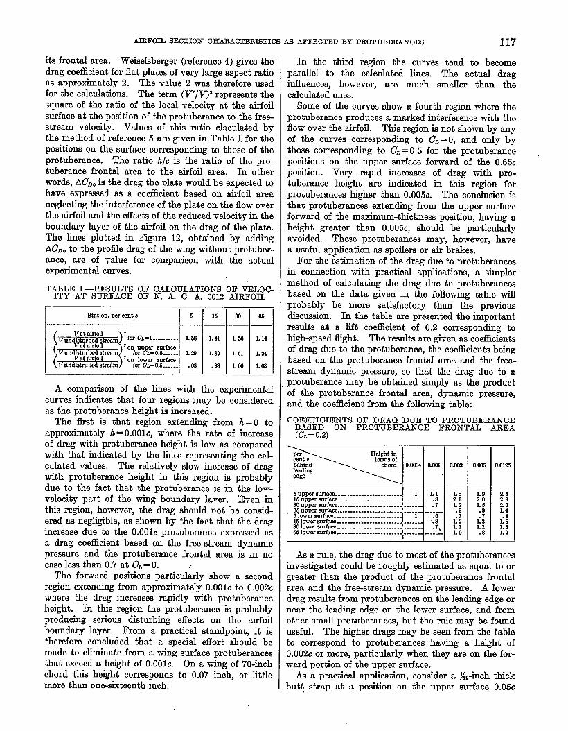
The effects on maximum lift of the protuberances ofvarious heights are also shown in Figures 2 to 10. Theeffect can be seen more easily, however, horn the curvesof Figure 13 representing the variation of mtiumlift with protuberance height for the vE&ous positions
1.61 I I i I I I I I I I I I I I
‘I—tti—t..
0 .002 .004 -wHeighf of pro fuberme x c
~GuEE 13.-Varfation of =RIIn l&ttiA@kanc3 hekht. ROtII-
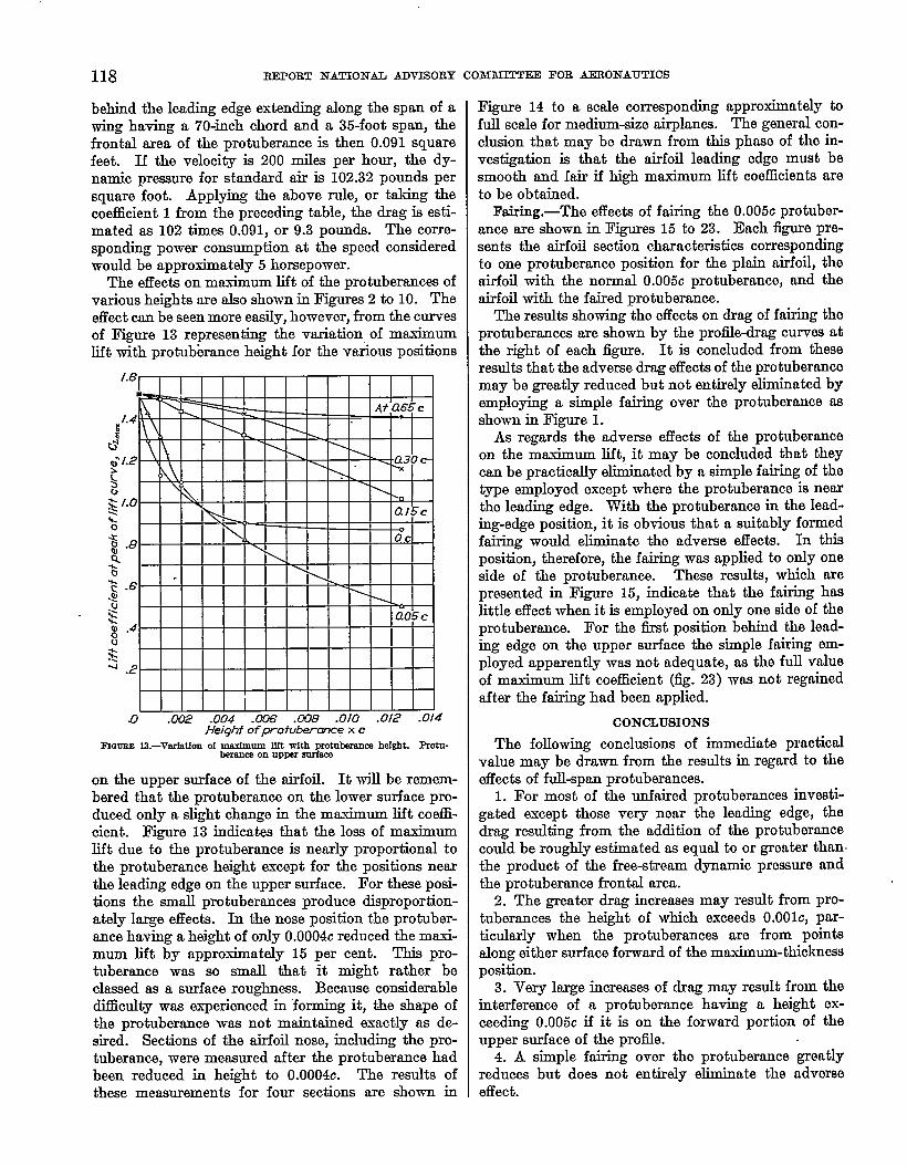
on the upper surface of the airfoil. It will be remem-bered that the protuberance on the lower surface pro-duced only a slight change in the maximum lift coeffi-cient. Figure 13 indicatw that the 10s9 of maximumlift due to the protuberance is nearly proportional tothe protuberance height except for the positions nearthe leading edge on the upper surface. For these posi-tions the small protuberances produce disproportion-ately large effects. In the nose position the protuber-ance having a height of only 0.0004c reduced the maxi-mum lift by approximately 15 per cent. This pro-tuberance was so small that it might rather beclassed as a surface roughness. Because considerablediflicu& was experienced in ‘forming it, the shape ofthe protuberance was not maintained exactly as de-sired. Sections of the airfoil nose, including the pro-tuberance, were measured after the protuberance hadbeen reduced in height to 0.0004c. The results ofthese measurements for four sections are shown in
Figure 14 to a scale corresponding approximately tofull scale for medium-size airplanes The general con-clusion that may be drawn from this phase of the in-vestigation is that the airfoil leading edge must besmooth and fair if high maximum lift coe5ciente areto be obtained.
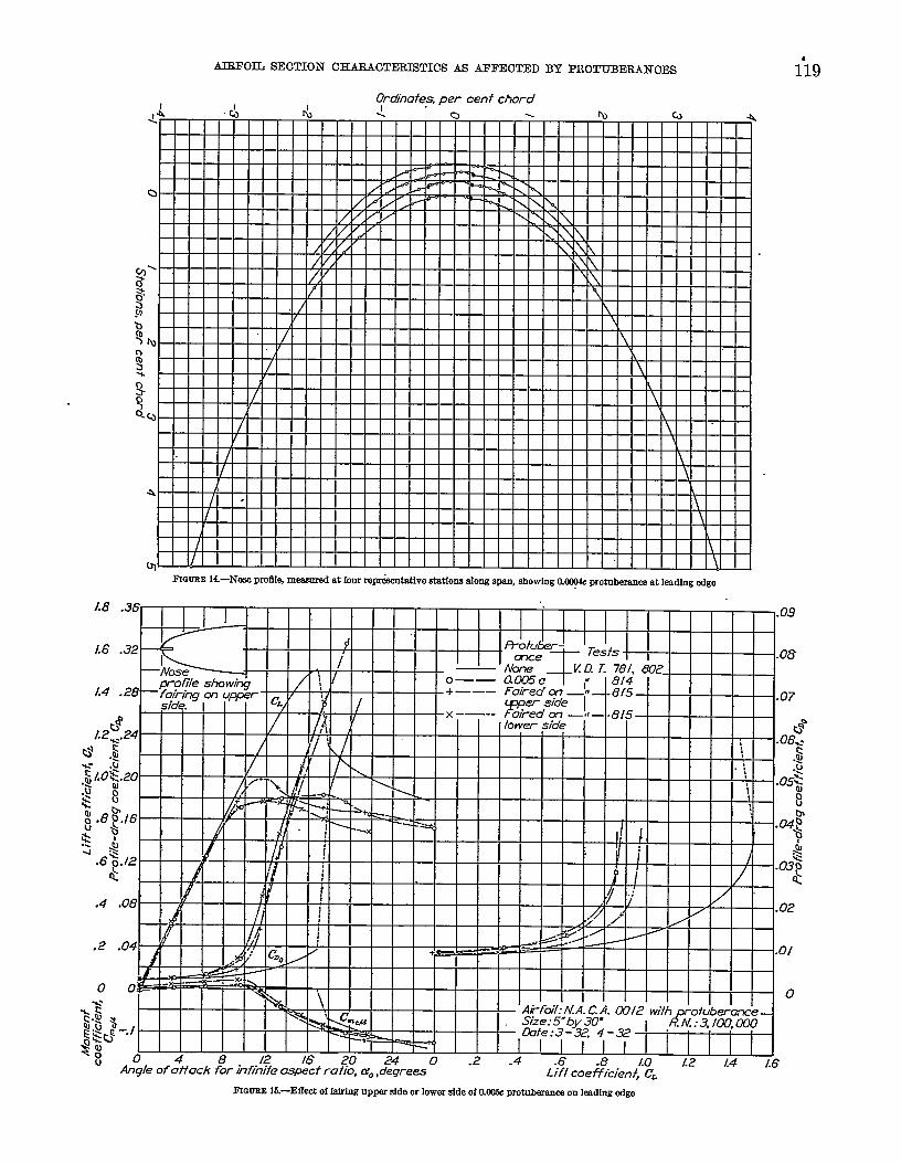
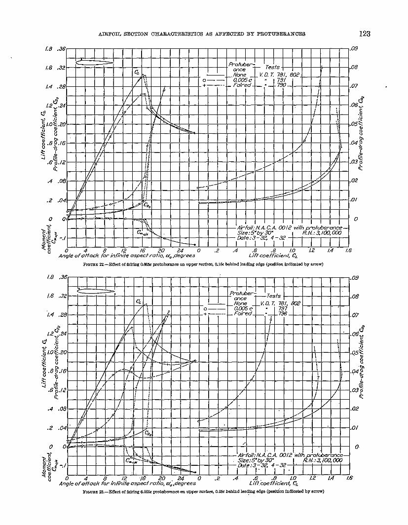
Faking,-The effects of fairing the 0.005c protuber-ance are shown in Figures 15 to 23. Each figure pre-sents the airfoil section characteristics correspondingto one protuberance position for the plain airfoil, theairfoil with the normal 0.005c protuberance, and theairfoil with the faired protuberance.
The results showing the effects on drag of faking theprotuberances are shown by the profle-drag curves atthe right of each figure. It is concluded from theseresults that the adverse drag effects of the protuberancemay be greatly reduced but not entirely eliminated byemplofig a simple fairing over the protuberance asshown in Figure 1.
As regards the adverse eflects of the protuberanceon the maximum lift, it may be concluded that theycan be practically eliminated by a simple fairing of thetype employed except where the protuberance is nearthe leading edge. With the protuberance in the leod-ing-edge position, it is obvious that a suitably formedfairing would eliminate the adveme effects. In thisposition, therefore, the fairing was applied to only oneside of the protuberance. These results, which mepresented in Figure 15, indicate that the faking haalittle effect when it is employed on only one side of theprotuberance. For the first position behind the lead-ing edge on the upper surface the simple fairing em-ployed apparently was not adequate, as the full valueof maximum lift coefficient (fig. 23) was not regainedafter the fairing had been applied.
CONCLUSIONS
The following conclusions of immediate practicalvalue may be drawn from the results in regard to theeffects of full-span protuberances.
1. For most of the unfaired protuberances investi-gated except those very near the lending edge, thedrag resulting from the addition of the protuberancecould be roughly estimated as equal to or greater than,the product of the free-stream dynamic pressure andthe protuberance flontal area.
2. The greater drag increnaes may rcsndt from pro-tuberances the height of which exceeds 0.00Ic, par-ticularly when the protuberances are from pointsalong either surface forward of the maximum-thicknessposition.
3. Very large increases of drag may result from theinterference of a protuberance having a height ex-meding 0.005c if it is on the forward portion of theupper surface of the profile.
4. A simple fairing over the protuberance greatlyreduces but does not entirely eliminate the adverseeffect.
AIRFOHJ SECTION CHARACTEEISTIC!S AS AFFEOTED BY PEOTUBEEANOES i19
~GUEE 14.-Nme pmffl~ m@smW3 at four repi%emtatfve statfona along ~, ehowfng O.W protubruanm at kadfng edge
‘8“3’rnTm—rn
FI13UEEI&—Effect of fafrfng rrp~ side or lower side of Cdlll& protuberance on lemifng edge

nb EEPOET NATIONAL ADVISOItY COMM3TTEE FOE AERONAUTICS “
/.8
1.6
1.4
o 0
-.1
0 4 8 12 16 20 24 0 .2 .4 .8 L2 f.4 k6Angle of affack for infinite o.specfrafio, UO,degrees L)?f coefficien+~;~
FfGms 16.-Eff@ of Mrfng W13c protzkaanm on loti _ O.fW Imbfnd leading @ilge @@itlon indicntd by arrow)
Fmmc? 17.—E@ of Mrbu O.W P tnbmnm on lower anrfma Um Mhfndlmdfw~ Wtkm hdhti by~w)

v.
AIEFOIL SECTION OHARAOTEEISTI& AS AJ?FEOTEDBY PliOTUBEBANOES 121
FKYIJEBl&—Effe@t of hiring CdXI& pmfuberanca on lower wrfaq O.Kk bebfnd lading @e (poskfon fndkated by arrow)
1.8 . 09
1.6. 08
1.4. 07
0
1.2:.9
06$.-
u u~- ‘. -— 1 I { I I
0
‘~ c +t @fwl: N/l.C.A. 0312 with-.,4 b Slze:5”by 30”
i ,d%$%a%–!@? -./
1“&te:3.32, 4-32
u 04 8 1216,?0240.2 .4 .6 .&LO/.2- “Angle of affack for inhiv?e aspecf ratio, &O,degrees
“1.4- L8Liffcoefficienf, CL
.
~GmE lQ—Efkat of faking O.@k SIrotnb@ence on lower mrfacq 0.6& b3blnd lexiing edge Qxuftion indfmtc=i by &row)
407~9 ,

122 EEPOIiT NATIONAL ADVISORY COMbDTTEE FOB AERONAUTICS
L8
1.6
L4
FmunEm.-EffwtoffakingO.OWprotukam onumwmrfm%M& bdnd ImdiwedmWtim ldkakd bymm)
I
I
I(J
o O& ~*.
1.$ ~ I I Size:5fbv.39” I kh!:3,1m.000 Ig$~ -.1 -
3; 0 4 8 J2 16 2~u
Angle of off ack for in%ife aspecf rafio, do,d;$ees - ‘- “” L~fi-c4eREcien+j”G “’- “-” ““-
- LWe:~-”S, 4-32 1 . .
I i , , , t , 1n PA n ? d .G ..4 10 [2 1.4 /.6
i
FIOVBE 21.-Effect of filrimg 0.- potmkanm cm upper _ CL3CkMhJmd leadfng W@ (pmition indkati by orrow)
AIRPOIL SEOTION CHAEA.OTEIWSTICSAS AXI”EIOTWDBY PBOTUBEEANOES 123
fiOUBE 22-Effect of ffI&fnK flOXi PMhdmramm cm UPPW surfs% O.lECbebfnd l=dfns 6@N @9ftion fndkstd by WIWW)
/,8 .36
11-.09
,6 32 ~ I I. . Proh.berJ
0.~ ~Te;ts .08
----- ----I -. b. I I I I I I -L1’wn?e _l_Ku. 1. 16[, u
I 797 I;.4 .28
/H#H
.07
~9Q ,.{ &t,
W?ii Yiili’iii iiti-~i. iiii. .L--k&PTi iiil/ ::: 1,
.2
0
L.=. I I I I I I I I I I I I I I II I i
i I I I I,.
.04 .0/
0 0
-./
0 4 8 12 16 20 24 0 .2 .4 .6. LoAngle of off act%for infihife aspecf rcdio, ti~,degrees
[2” 1.4 [6’Lifi,coe&ienf, CL
~GUEE 23.-Effwtof fafrfng O.C@& PIwtubaranca cm UPp@r smfam O.O& behind lea% M@ @ftfk fndkated by arrow)

---- - ----—-——-A-. . . . , -
124 REPOBT NATIONAL ADVISORY CIOMMITTEE FOB AEBONAUTIOS
5. The efkt of a protuberance on the maximumlift is unimportant when the protuberance is” on thelower surface, but becomee very important, even for aprotuberance so small that it would ordinarily beclassed ns a surface roughness, ss the position ap-proaches the-lending edge along the upper surface.
kGLEY MEMORIAL kMLONAUTICAL LABORATORY,
NATIONAL &wIsoEY COMMITTEE FOR AERONAUTICS,
LANGLEY FIELD, VA., Jdy Ii, 19%?!.
REFERENCES
1. Ower, E.: Interference. Roy. Aero. Sot. Jour., July, 1932,
pp. 531-77.2. Jacoba, Eastman N., and Abbott, Ira H.: The N. A. C. A.
Variable-Denaity Wind Tunnel. T. IL No. 416, N. A.C. A., 1932.
3. Jacobs, Eastman N.: Ted-s of Sk Symmetrical Airfoils inthe Variable-Density Wind Tunnel. T. N. No. 3S6,N. A. C. A., 1931.
4 Wieselsberger, C., and Betz, A.: Ergebniwe der Aero-dynarniachenVersuclwmstalt zu GMingen. Oldenbourg(Mtlnchen), 1923. II Lieferung, pp. 33-34.
5. Theodomen, T.: Theory of Wing Sections of ArbitrmyShape. T. R No. 411, N. A. C. A., 1931.