Embed Size (px)
Citation preview
2014
Airfoils Supporting Non-unique Transonic Solutions
for Unsteady Viscous Flows
Kui Ou, ∗
Flight Sciences Department, Honda Aircraft Company, Greensboro, NC 27410
Antony Jameson,†
Aeronautics and Astronautics Department, Stanford University, Stanford, CA 94305
John C. Vassberg, ‡
Advanced Concepts Design Center, Boeing Commercial Airplanes, Long Beach, CA 90846
Non-unique numerical solutions of transonic flows have been found, first for potential
flow equation, and later for Euler and RANS equations. The studies conducted so far
have been mostly limited to steady state flow simulations. It is believed that unsteady
simulations are needed to gain a better understanding of the evolution and stability of
these flows. This paper re-examined a set of four recently designed symmetric airfoils that
have been found to support non-unique solutions in steady transonic flows in a narrow
band of transonic Mach numbers. Unsteady RANS solutions have been performed for
these four airfoils in the transonic regime. Results indicate that all four airfoils exhibit
unsteady non-unique transonic solutions. The unsteady non-unique solutions occur over a
wider band of transonic Mach numbers than the steady non-unique solutions.
I. Introduction
Non-unique solutions of the transonic potential flow equation were discovered by Steinhoff and Jameson1
(1981), who obtained lifting solutions for a symmetric Joukowski airfoil at zero angle of attack in a narrowrange of Mach numbers in the neighborhood of Mach 0.85. This non-uniqueness could not be duplicated withthe Euler equations and it was conjectured by Salas et al2 (1983) that the non-uniqueness was a consequenceof the isentropic flow approximation. Subsequently, however, Jameson3 (1991) discovered several airfoilswhich supported non-unique solutions of the Euler equations in a narrow Mach band. These airfoils werelifting.
The question of non-unique transonic flows was re-examined by Hafez and Guo4–6 (1999) who formedboth lifting and non-lifting solutions for a 12 percent thick symmetric airfoil with parallel sides from 25 to75 percent chord in a Mach range from 0.825 to 0.843. The question was further pursued in detail in a seriesof studies by Kuz’min and Ivanova7–11 (2004,2006) who confirmed the results of Hafez and Guo, and alsoshowed that airfoils with positive curvature everywhere could support non-unique solutions.
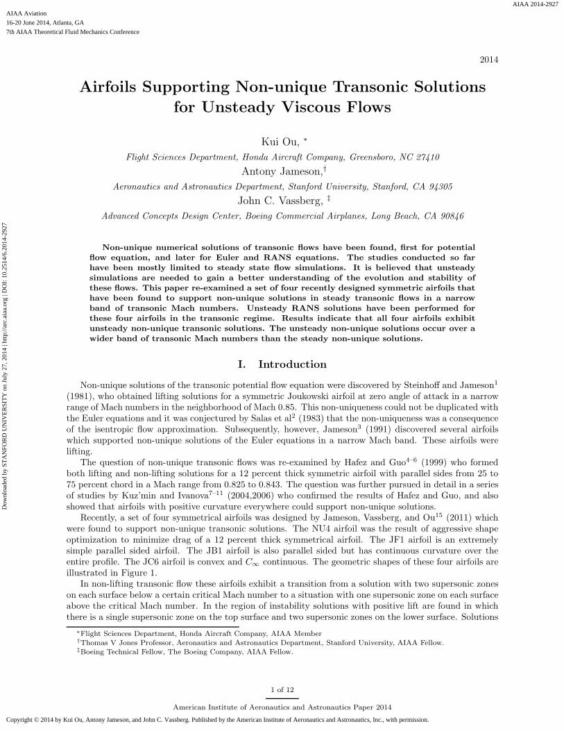
Recently, a set of four symmetrical airfoils was designed by Jameson, Vassberg, and Ou15 (2011) whichwere found to support non-unique transonic solutions. The NU4 airfoil was the result of aggressive shapeoptimization to minimize drag of a 12 percent thick symmetrical airfoil. The JF1 airfoil is an extremelysimple parallel sided airfoil. The JB1 airfoil is also parallel sided but has continuous curvature over theentire profile. The JC6 airfoil is convex and C∞ continuous. The geometric shapes of these four airfoils areillustrated in Figure 1.
In non-lifting transonic flow these airfoils exhibit a transition from a solution with two supersonic zoneson each surface below a certain critical Mach number to a situation with one supersonic zone on each surfaceabove the critical Mach number. In the region of instability solutions with positive lift are found in whichthere is a single supersonic zone on the top surface and two supersonic zones on the lower surface. Solutions
∗Flight Sciences Department, Honda Aircraft Company, AIAA Member†Thomas V Jones Professor, Aeronautics and Astronautics Department, Stanford University, AIAA Fellow.‡Boeing Technical Fellow, The Boeing Company, AIAA Fellow.
1 of 12
American Institute of Aeronautics and Astronautics Paper 2014
Dow
nloa
ded
by S
TA
NFO
RD
UN
IVE
RSI
TY
on
July
27,
201
4 | h
ttp://
arc.
aiaa
.org
| D
OI:
10.
2514
/6.2
014-
2927
7th AIAA Theoretical Fluid Mechanics Conference
16-20 June 2014, Atlanta, GA
AIAA 2014-2927
Copyright © 2014 by Kui Ou, Antony Jameson, and John C. Vassberg. Published by the American Institute of Aeronautics and Astronautics, Inc., with permission.
AIAA Aviation
AA
(a) NU4 airfoil (b) JF1 airfoil++++++ +++++
(c) JC6 airfoil (d) JB1 airfoilFigure 1. Geometric shapes of a set of 4 symmetric airfoils admitting non-unique transonic solutions.
with negative lift which are the mirror images of the solutions with positive lift. The CL − α plots ofthese airfoils exhibit three branches at zero angle of attack corresponding to a P-branch with positive lift, aZ-branch with zero lift, and a N-branch with negative lift. The results for NU4 and JB1 airfoils are shownin Figure 2. For further details of the study, please refer to Jameson, Vassberg, and Ou (2011).15
!!"# !!"!$ ! !"!$ !"#!!"#
!!"!%
!!"!&
!!"!'
!!"!(
!
!"!(
!"!'
!"!&
!"!%
!"#
)*+,-./0.)1123456-+7--8
9/-00:3:-*1./0.;:01
<='.):70/:,!"%'!.>23?
@,/%(A.>-B?.5C(!D&'8
.
.
E!F72*3?
G!F72*3?
<!F72*3?
!!"# !!"!$ !!"!% !!"!& !!"!' ! !"!' !"!& !"!% !"!$ !"#!!"#
!!"!$
!!"!%
!!"!&
!!"!'
!
!"!'
!"!&
!"!%
!"!$
!"#
()*+,-./-(0012345,*6,,78
9.,//:2:,)0-./-;:/0
<=#-(:6/.:+!"$'>-?12@
A+.$'B-?,7@-4C'!D%&8
-
-
E!=61)2@
F!=61)2@
G!=61)2@
(a) NU4 airfoil (b) JB1 airfoilFigure 2. CL − α plots of NU4 and JB1 airfoils. The overlapping of the P, Z, and N branches indicate non-uniquenessof flow solutions.
The reported non-unique solutions were obtained based on Euler equations. The Euler solver (FLO82)13
uses a multigrid solution procedure, in combination with variable local time stepping and residual averaging.These procedures could potentially stabilize an otherwise unstable solution. There is a need to further verifythe findings established by the Euler solutions using unsteady Navier-Stokes solutions.
II. Non-unique Transonic Solutions: Unsteady Viscous Flows
Flow simulations based on unsteady Navier-Stokes equations (UFLO103)14 were performed in this paper.A Reynolds number of 6,000,000 has been used for all viscous flows. The airfoils all have C-topology mesheswhich contain 320 cells in the clockwise direction and 64 cells in the normal direction. The simulationprocedure is as follows. For a given Mach number, an angle of attack is chosen, and the flow is computeduntil sufficient convergence is reached. The time-averaged lift coefficient is then recorded. This makes a datapoint in the Cl-alpha sweep curve. To collect the next data point, the previously converged flow solutionwas used as the initial condition. The time-accurate RANS simulations were performed for all four airfoils.The results for NU4 airfoil are discussed in further details below.
II.A. NU4 Airfoil - Geometry
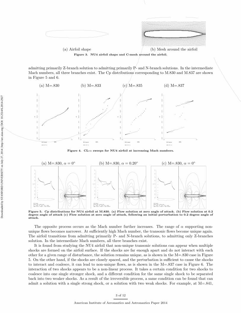
NU4 airfoil is a consequence of a shape optimization study for symmetric airfoils in transonic flow,12 in whichan attempt was made to find a 12 percent thick airfoil with a shock free solution at Mach 0.84. The airfoilshape and the mesh near the airfoil are shown in Figure 3.
The Cl − α sweep shows that NU4 airfoil assumes unique solution at Mach 0.830. As the Mach numberfurther increases, non-unique transonic solutions are observed, i.e. multiple Cl solutions are supported fora given Mach number and α. As the Mach number increases, the range of α that can support non-uniquesolutions widens. This is shown in Figure 4. In going from M.830 to M.837, the airfoil transitions from
2 of 12
American Institute of Aeronautics and Astronautics Paper 2014
Dow
nloa
ded
by S
TA
NFO
RD
UN
IVE
RSI
TY
on
July
27,
201
4 | h
ttp://
arc.
aiaa
.org
| D
OI:
10.
2514
/6.2
014-
2927
AA
(a) Airfoil shape (b) Mesh around the airfoil
Figure 3. NU4 airfoil shape and C-mesh around the airfoil.
admitting primarily Z-branch solution to admitting primarily P- and N-branch solutions. In the intermediateMach numbers, all three branches exist. The Cp distributions corresponding to M.830 and M.837 are shownin Figure 5 and 6.
(a) M=.830 (b) M=.833 (c) M=.835 (d) M=.837
NU4 Airfoil
GRID 320 X 64
-.2
E+
00
-.2
E+
00
-.1
E+
00
-.5
E-0
10
.0E
+0
00
.5E
-01
0.1
E+
00
0.2
E+
00
0.2
E+
00
Cl
-0.25 0.25
alpha
+++
++ +
++
++
++
+++++++++
++
++
++
++
++
++
++
+++
++
++
++
++
++++++
++
++
++
++
++
++
++
++ + +
++
++
++
++++
++++++
++
++
++
++
++
++
+++
NU4 Airfoil
GRID 320 X 64
-.2
E+
00
-.2
E+
00
-.1
E+
00
-.5
E-0
10
.0E
+0
00
.5E
-01
0.1
E+
00
0.2
E+
00
0.2
E+
00
Cl
-0.25 0.25
alpha
+++
++
++
++
+
+
+
+++++++++++++
+
++
+
++
++
++
+++
++
+
+
+
+
++++++++++ + + +
+
++
+
++
+
++
++
++
++
+
+
+
+
+++++++++++++
+
++
+
++
++
++
++
NU4 Airfoil
GRID 320 X 64
-.2
E+
00
-.2
E+
00
-.1
E+
00
-.5
E-0
10
.0E
+0
00
.5E
-01
0.1
E+
00
0.2
E+
00
0.2
E+
00
Cl
-0.25 0.25
alpha
+++
++
+
+
+
+
+ + + + ++++++++++++++++++++
+
+
+
++
+
+
+
+++++++++++++ + + + + + + + + + ++
+
+
+
+
+
+
+
++ + + + +++++++++++++++++++
++
+
+
+
NU4 Airfoil
GRID 320 X 64
-.2
E+
00
-.2
E+
00
-.1
E+
00
-.5
E-0
10
.0E
+0
00
.5E
-01
0.1
E+
00
0.2
E+
00
0.2
E+
00
Cl
-0.25 0.25
alpha
++
+
+
+
+ + + + + + + + +++++++++++++++++++++++
+
+
+
+++++++++++++++ + + + + + + + + + + ++ + +
+
+
+
+ + + + + + +++++++++++++++++++++++
+
Figure 4. CL-α sweeps for NU4 airfoil at increasing Mach numbers.
(a) M=.830, α = 0◦ (b) M=.830, α = 0.20◦ (c) M=.830, α = 0◦
NU4 Airfoil
MACH 0.830 ALPHA 0.000
CL 0.0000 CD 0.0172 CM 0.0000
GRID 320X 64 NSTEP 1 RES 0.190E+00
0.1
E+
01
0.8
E+
00
0.4
E+
00
-.2
E-1
5-.
4E
+0
0-.
8E
+0
0-.
1E
+0
1-.
2E
+0
1-.
2E
+0
1
CP
++++
+++
++
++
++
++
++
+
+
+
+++
++
+++++++++++++++++++++++++++
+
+
++
++++++++
+++++++
++++
++++
++++
+++
+
+
+
+
+
+
+
+
+
++++++++
+++
+
+
+
+
+
+
+
+
+
+++
+++++++++++++++++++++++++++
++
+
++++
++++++
++++++
++++++++++
+++++++
+
+
+
+++++++++++++++++
NU4 Airfoil
MACH 0.830 ALPHA 0.200
CL 0.0851 CD 0.0170 CM -0.0002
GRID 320X 64 NSTEP 17 RES 0.450E+01
0.1
E+
01
0.8
E+
00
0.4
E+
00
-.2
E-1
5-.
4E
+0
0-.
8E
+0
0-.
1E
+0
1-.
2E
+0
1-.
2E
+0
1
CP
+++++
++
++
++
++
+++
+
+
+
+
+++
++
+++++++++++++++++++++++++++++++++++
+++
+
+
+++
+++++
++++
++++
++
+++
+
+
+
+
+
+
+
+
+
++++++++
+++
+
+
+
+
+
+
+
+
+
+++
+++++++++++++++++++++++++++++++++++++++
++
+
+
+++++
+++++++
+++++
+++
+
+
+
+++++++++++++
++++
NU4 Airfoil
MACH 0.830 ALPHA 0.000
CL 0.0014 CD 0.0171 CM -0.0007
GRID 320X 64 NSTEP 33 RES 0.236E+01
0.1
E+
01
0.8
E+
00
0.4
E+
00
-.2
E-1
5-.
4E
+0
0-.
8E
+0
0-.
1E
+0
1-.
2E
+0
1-.
2E
+0
1
CP
+++++
++
++
++
++
++
+
+
+
+
+
+++
++
+++++++++++++++++++++++++++
+
+
++
++++++++
+++++++
++++
++++
++++
+++
+
+
+
+
+
+
+
+
+
++++++++
+++
+
+
+
+
+
+
+
+
+
+++
+++++++++++++++++++++++++++
++
+
++++
++++++
++++++
++++++++++
++++
+++
+
+
+
+
++++++++++++++++
Figure 5. Cp distributions for NU4 airfoil at M.830. (a) Flow solution at zero angle of attack. (b) Flow solution at 0.2degree angle of attack (c) Flow solution at zero angle of attack, following an initial perturbation to 0.2 degree angle ofattack.
The opposite process occurs as the Mach number further increases. The range of α supporting non-unique flows becomes narrower. At sufficiently high Mach number, the transonic flows become unique again.The airfoil transitions from admitting primarily P- and N-branch solutions, to admitting only Z-branchessolution. In the intermediate Mach numbers, all three branches exist.
It is found from studying the NU4 airfoil that non-unique transonic solutions can appear when multipleshocks are formed on the airfoil surface. If the shocks are far enough apart and do not interact with eachother for a given range of disturbance, the solution remains unique, as is shown in the M=.830 case in Figure5. On the other hand, if the shocks are closely spaced, and the perturbation is sufficient to cause the shocksto interact and coalesce, it can lead to non-unique flows, as is shown in the M=.837 case in Figure 6. Theinteraction of two shocks appears to be a non-linear process. It takes a certain condition for two shocks tocoalesce into one single stronger shock, and a different condition for the same single shock to be separatedback into two weaker shocks. As a result of the irreversible process, a same condition can be found that canadmit a solution with a single strong shock, or a solution with two weak shocks. For example, at M=.841,
3 of 12
American Institute of Aeronautics and Astronautics Paper 2014
Dow
nloa
ded
by S
TA
NFO
RD
UN
IVE
RSI
TY
on
July
27,
201
4 | h
ttp://
arc.
aiaa
.org
| D
OI:
10.
2514
/6.2
014-
2927
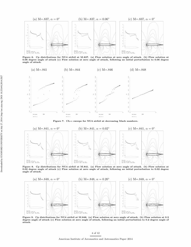
(a) M=.837, α = 0◦ (b) M=.837, α = 0.06◦ (c) M=.837, α = 0◦
NU4 Airfoil
MACH 0.837 ALPHA 0.000
CL 0.0000 CD 0.0179 CM 0.0000
GRID 320X 64 NSTEP 1 RES 0.210E+00
0.1
E+
01
0.8
E+
00
0.4
E+
00
-.2
E-1
5-.
4E
+0
0-.
8E
+0
0-.
1E
+0
1-.
2E
+0
1-.
2E
+0
1
CP
+++++
+++
++
++
++
++
+
+
+
+++
+
++
++++++++++++++
++++
+
+
+++
+++++++++++++
++++++++
+++++
++++
+++++
+++
+
+
+
+
+
+
+
+
+
++++++++
+++
+
+
+
+
+
+
+
+
+
+++
+++++++++++++++++++++++++++++++++++++
+
+
++++
+++
+++++++++
+++++
+++
+
+
+
+
++++++++++++++++
NU4 Airfoil
MACH 0.837 ALPHA 0.058
CL 0.1282 CD 0.0160 CM -0.0222
GRID 320X 64 NSTEP 4 RES 0.321E+01
0.1
E+
01
0.8
E+
00
0.4
E+
00
-.2
E-1
5-.
4E
+0
0-.
8E
+0
0-.
1E
+0
1-.
2E
+0
1-.
2E
+0
1
CP
+++++
+++
++
++
++
+++
+
+
+
++++
+++++++++++++++++++++++++++++++++
++
+
++
++++++
+++++
++++
++++
++
+++
+
+
+
+
+
+
+
+
+
++++++++
+++
+
+
+
+
+
+
+
+
+
+++
+++++++++++++++++++++++++++++++++++++++++++++++++++++
++++++
+
+
+
++++++++++++++
+++++++
NU4 Airfoil
MACH 0.837 ALPHA 0.000
CL 0.1192 CD 0.0156 CM -0.0303
GRID 320X 64 NSTEP 33 RES 0.260E+02
0.1
E+
01
0.8
E+
00
0.4
E+
00
-.2
E-1
5-.
4E
+0
0-.
8E
+0
0-.
1E
+0
1-.
2E
+0
1-.
2E
+0
1
CP
++++++
++
+++++++
+
+
+
+
+
++++
+++++++++++++++++++++++++++
++++
+
+++
+++++++++
+++++
++++
++++
++
+++
+
+
+
+
+
+
+
+
+
++++++++
+++
+
+
+
+
+
+
+
+
+
+++
+++++++++++++++++++++++++++++++++++++++++++++++++++
++++++++++++++++
++
+
+
+++++
+++++++
Figure 6. Cp distributions for NU4 airfoil at M.837. (a) Flow solution at zero angle of attack. (b) Flow solution at0.06 degree angle of attack (c) Flow solution at zero angle of attack, following an initial perturbation to 0.06 degreeangle of attack.
(a) M=.841 (b) M=.844 (c) M=.846 (d) M=.848
NU4 Airfoil
GRID 320 X 64
-.2
E+
00
-.2
E+
00
-.1
E+
00
-.5
E-0
10
.0E
+0
00
.5E
-01
0.1
E+
00
0.2
E+
00
0.2
E+
00
Cl
-0.25 0.25
alpha
++
+
+ + + ++ + + + + + +++++++++++++
++++++
++
++
++
+
+
++++++++++++++ + + + + + ++ + + +
++
++
++
+
+
+ ++ + + +++++++++++++++++
+++
++
++
NU4 Airfoil
GRID 320 X 64
-.2
E+
00
-.2
E+
00
-.1
E+
00
-.5
E-0
10
.0E
+0
00
.5E
-01
0.1
E+
00
0.2
E+
00
0.2
E+
00
Cl
-0.25 0.25
alpha
++
+
+ ++
++ +
+ + + + +++++++++++++++
++
+++
+
+
+
+
++
+++
++++++++++++ + + + ++ +
++
++
++
+
+
+
++
++ + + + + ++++++++++++++
++
++
+++
+
+
+
NU4 Airfoil
GRID 320 X 64
-.2
E+
00
-.2
E+
00
-.1
E+
00
-.5
E-0
10
.0E
+0
00
.5E
-01
0.1
E+
00
0.2
E+
00
0.2
E+
00
Cl
-0.25 0.25
alpha
++ ++
++
+
++
++ + + ++++++++++++
++
++
+
+
+
+++
++
+
+
++
+++++++++++++ + + +
++
++
++
+
++ +
++
+
+
++
+ ++ + ++++++++++++
++
++
+
+
+
+++
++
NU4 Airfoil
GRID 320 X 64
-.2
E+
00
-.2
E+
00
-.1
E+
00
-.5
E-0
10
.0E
+0
00
.5E
-01
0.1
E+
00
0.2
E+
00
0.2
E+
00
Cl
-0.25 0.25
alpha
+++
+ ++
++ + + + + + +++++++++++++++
+++
++++
++
+++
++++++++++++
++ + + + + ++
+ ++
++ + +
++
+ ++
+ + + + + +++++++++++++++
+++
++++
++
Figure 7. CL-α sweeps for NU4 airfoil at decreasing Mach numbers.
(a) M=.841, α = 0◦ (b) M=.841, α = 0.02◦ (c) M=.841, α = 0◦
NU4 Airfoil
MACH 0.841 ALPHA 0.000
CL 0.0035 CD 0.0175 CM -0.0010
GRID 320X 64 NSTEP 1 RES 0.412E+00
0.1
E+
01
0.8
E+
00
0.4
E+
00
-.2
E-1
5-.
4E
+0
0-.
8E
+0
0-.
1E
+0
1-.
2E
+0
1-.
2E
+0
1
CP
+++++
+++
++
++
++
++
+
+
+
+++
+
++
++++++
++++
+
+
+++
++++++++++++++++++
+++++++++
+++++
++++
++++
+++
+++
+
+
+
+
+
+
+
+
+
++++++++
+++
+
+
+
+
+
+
+
+
+
+++
+++++++++++++++++++++++++++++++++++++++++++++
++
+++++
++++
++++
+++
+
+
+
+
++++++++++++++++
NU4 Airfoil
MACH 0.841 ALPHA 0.020
CL 0.0864 CD 0.0176 CM -0.0107
GRID 320X 64 NSTEP 2 RES 0.389E+02
0.1
E+
01
0.8
E+
00
0.4
E+
00
-.2
E-1
5-.
4E
+0
0-.
8E
+0
0-.
1E
+0
1-.
2E
+0
1-.
2E
+0
1
CP
++
++++++
+
+
+
+
+++
++
+
+
+
+++
++
++++++++++++++++++++++++
+
++
+++++++
+++++++
++++++
++++
++++
+++
+++
+
+
+
+
+
+
+
+
+
++++++++
+++
+
+
+
+
+
+
+
+
+
+++
++++++++++++++++++++++++++++++++++++++++++++++++
+++++++++++++
+
+
+
+
+
+
+++
+
++++
+
+
++++
++
NU4 Airfoil
MACH 0.841 ALPHA 0.000
CL 0.0580 CD 0.0182 CM -0.0034
GRID 320X 64 NSTEP 33 RES 0.595E+02
0.1
E+
01
0.8
E+
00
0.4
E+
00
-.2
E-1
5-.
4E
+0
0-.
8E
+0
0-.
1E
+0
1-.
2E
+0
1-.
2E
+0
1
CP
++
+++++++
+
+
+
+
+++
+
+
+
++
+
+
+
++
++++++++++++++++++++
+
+
++
++++++
+++++++++
++++++
++++
++++
++++
+++
+
+
+
+
+
+
+
+
+
++++++++
+++
+
+
+
+
+
+
+
+
+
+++
+++++++++++++++++++++++++++++++++++++++++++++++++
++++++++++++
+
+
+
+
+
+++
++
+++
+
+
++++
+++
Figure 8. Cp distributions for NU4 airfoil at M.841. (a) Flow solution at zero angle of attack. (b) Flow solution at0.02 degree angle of attack (c) Flow solution at zero angle of attack, following an initial perturbation to 0.02 degreeangle of attack.
(a) M=.848, α = 0◦ (b) M=.848, α = 0.20◦ (c) M=.848, α = 0◦
NU4 Airfoil
MACH 0.848 ALPHA 0.000
CL 0.0041 CD 0.0177 CM -0.0028
GRID 320X 64 NSTEP 1 RES 0.570E+01
0.1
E+
01
0.8
E+
00
0.4
E+
00
-.2
E-1
5-.
4E
+0
0-.
8E
+0
0-.
1E
+0
1-.
2E
+0
1-.
2E
+0
1
CP
+++++
++
++
+++
+++
++
+
+
+
+
+++
+++++++++++++++++++++++++++++++++++
++++++++++
+++++
++++
+++++
+++
+
+
+
+
+
+
+
+
+
++++++++
+++
+
+
+
+
+
+
+
+
+
+++
++++++++++++++++++++++++++++++++++++++++++++++++++++
+++++++
+++
+
+
+++
++++++++++++++++
NU4 Airfoil
MACH 0.848 ALPHA 0.200
CL 0.0528 CD 0.0194 CM -0.0062
GRID 320X 64 NSTEP 17 RES 0.863E+00
0.1
E+
01
0.8
E+
00
0.4
E+
00
-.2
E-1
5-.
4E
+0
0-.
8E
+0
0-.
1E
+0
1-.
2E
+0
1-.
2E
+0
1
CP
+++++
++
++
++
++
++
+
+
+
+
+++
++
+++++++++++++++
+++++++++++++++++
++++++++++
++++++
++++
++++
+++
+++
+
+
+
+
+
+
+
+
+
++++++++
+++
+
+
+
+
+
+
+
+
++++
+++++++++++++++++++++++++++++++++++++++++++++++++
++++++++++
++
+
+
+
+++++++++++++++++++
NU4 Airfoil
MACH 0.848 ALPHA 0.000
CL 0.0037 CD 0.0186 CM -0.0090
GRID 320X 64 NSTEP 33 RES 0.687E+02
0.1
E+
01
0.8
E+
00
0.4
E+
00
-.2
E-1
5-.
4E
+0
0-.
8E
+0
0-.
1E
+0
1-.
2E
+0
1-.
2E
+0
1
CP
++
++
++
+
+
++
+
+
+++
+
+
+
+
+
+
+
+++++
+++++++++++++++++++++++++++++++++++++
++++++++
+++++
++++
++
+++
+
+
+
+
+
+
+
+
+
++++++++
+++
+
+
+
+
+
+
+
+
++++
+++++++++++++++++++++++++++++++++++++++++++++++
++++++++++++
+++
+++
+
+++
+
+
+
+
++++
++++
++
Figure 9. Cp distributions for NU4 airfoil at M.848. (a) Flow solution at zero angle of attack. (b) Flow solution at 0.2degree angle of attack (c) Flow solution at zero angle of attack, following an initial perturbation to 0.2 degree angle ofattack.
4 of 12
American Institute of Aeronautics and Astronautics Paper 2014
Dow
nloa
ded
by S
TA
NFO
RD
UN
IVE
RSI
TY
on
July
27,
201
4 | h
ttp://
arc.
aiaa
.org
| D
OI:
10.
2514
/6.2
014-
2927
small change in α caused two closely spaced shocks to coalesce into one single shock. The newly formed flowsupporting the single shock is stable even after the original α is restored. At M=.848, the airfoil admits onlya single shock on each airfoil surface. Without interaction of multiple shocks, the transonic flows remainunique.
III. Non-unique Transonic Flows: RANS Solution vs Euler Solution
In this section, comparisons are made between the unsteady RANS solution and the Euler solution forthe same airfoils at the same Mach numbers that admit non-unique solutions in the previous study usingEuler solver. Due to the presence of boundary layers, especially near the trailing edges, the exact location,strength, and resolution of the shocks tend to be different, but the global flow characteristics remain quitesimilar.
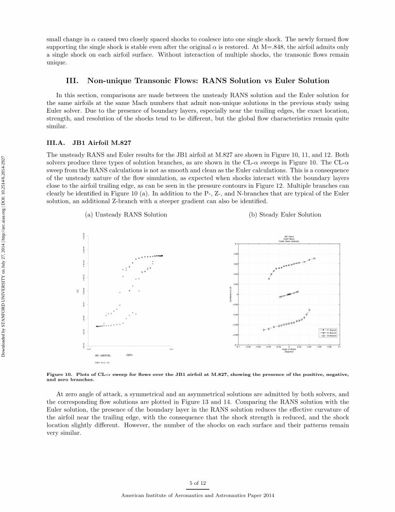
III.A. JB1 Airfoil M.827
The unsteady RANS and Euler results for the JB1 airfoil at M.827 are shown in Figure 10, 11, and 12. Bothsolvers produce three types of solution branches, as are shown in the CL-α sweeps in Figure 10. The CL-αsweep from the RANS calculations is not as smooth and clean as the Euler calculations. This is a consequenceof the unsteady nature of the flow simulation, as expected when shocks interact with the boundary layersclose to the airfoil trailing edge, as can be seen in the pressure contours in Figure 12. Multiple branches canclearly be identified in Figure 10 (a). In addition to the P-, Z-, and N-branches that are typical of the Eulersolution, an additional Z-branch with a steeper gradient can also be identified.
(a) Unsteady RANS Solution (b) Steady Euler Solution
JB1 AIRFOIL
GRID 384 X 128
-.2E
+00
-.2E
+00
-.1E
+00
-.5E
-01
0.0
E+
00
0.5
E-0
10.1
E+
00
0.2
E+
00
0.2
E+
00
Cl
-0.25 0.25
alpha
++
+
+ +
+ +
+ +
+
+ + + +++++++++++++++++++
+
+
++
+
++
+++
++++++++++++ + + + + + + + + + +
+
++
+
+
++
++
+
+ + + +++++++++++++++++++
+
++
+
+
!!"# !!"!$ !!"!% !!"!& !!"!' ! !"!' !"!& !"!% !"!$ !"#!!"#
!!"!$
!!"!%
!!"!&
!!"!'
!
!"!'
!"!&
!"!%
!"!$
!"#
()*+,-./-(0012345,*6,,78
9.,//:2:,)0-./-;:/0
<=#-(:6/.:+!"$'>-?12@
A+.$'B-?,7@-4C'!D%&8
-
-
E!=61)2@
F!=61)2@
G!=61)2@
Figure 10. Plots of CL-α sweep for flows over the JB1 airfoil at M.827, showing the presence of the positive, negative,and zero branches.
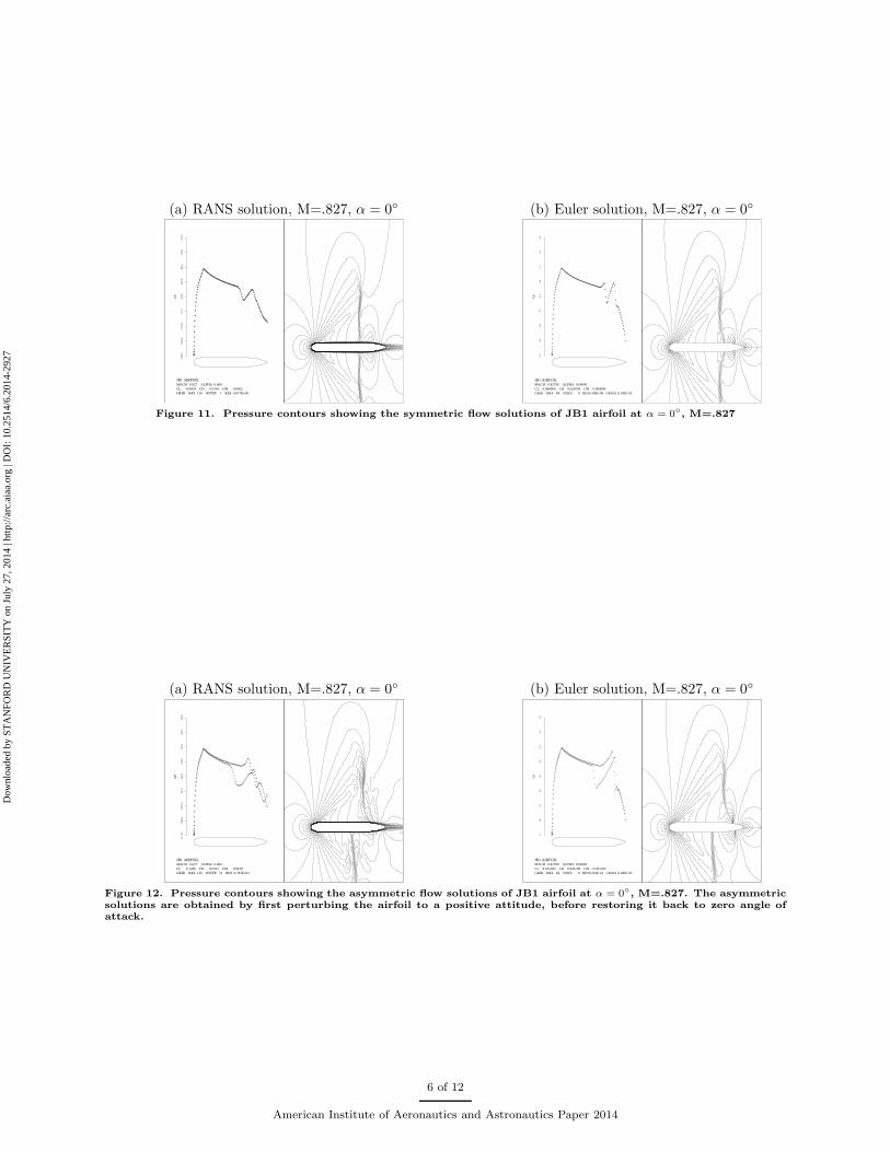
At zero angle of attack, a symmetrical and an asymmetrical solutions are admitted by both solvers, andthe corresponding flow solutions are plotted in Figure 13 and 14. Comparing the RANS solution with theEuler solution, the presence of the boundary layer in the RANS solution reduces the effective curvature ofthe airfoil near the trailing edge, with the consequence that the shock strength is reduced, and the shocklocation slightly different. However, the number of the shocks on each surface and their patterns remainvery similar.
5 of 12
American Institute of Aeronautics and Astronautics Paper 2014
Dow
nloa
ded
by S
TA
NFO
RD
UN
IVE
RSI
TY
on
July
27,
201
4 | h
ttp://
arc.
aiaa
.org
| D
OI:
10.
2514
/6.2
014-
2927
(a) RANS solution, M=.827, α = 0◦ (b) Euler solution, M=.827, α = 0◦
JB1 AIRFOIL
MACH 0.827 ALPHA 0.000
CL -0.0003 CD 0.0340 CM 0.0002
GRID 384X 128 NSTEP 1 RES 0.817E+00
0.1
E+
01
0.8
E+
00
0.4
E+
00
-.2E
-15
-.4E
+00
-.8E
+00
-.1E
+01
-.2E
+01
-.2E
+01
CP
++++
++++++++++++++++++
++++++
++
+++++
++++
+
+
++
+++++
++++++++
+++++++
++++++
++++++
++++
++++
++++
++++
++++++++++
+
+
+
+
+
+
+
+
+
+
+
+
+
+
+
+++++++
++
+
+
+
+
+
+
+
+
+
+
+
+
+
+
+
++++++++++++++++++++++++++++++++++++++++++++++++++++++++++
++
+
++++
++++
+++++++++++++++++++++++++++++++
+
JB1 AIRFOIL MACH 0.82700 ALPHA 0.00000CL 0.000000 CD 0.020558 CM 0.000000GRID 384X 64 NDES 0 RES0.109E-06 GMAX 0.100E-05
1.
2
0.8
0.
4
0.0
-0.
4 -
0.8
-1.
2 -
1.6
-2.
0
Cp
+
+++++++++++++
+++
+
+
+++
+++++++++++
+
+
+++++++++++++++++++++++
+++++++++++
+++++++++
++++++++
++++++
++++++
+++++
++++++++++
+
+
+
+
+
+
+
+
++++++++++
+++++
+
+
+
+
+
+
+
+
+++++++++++++++++++++++++++++++++++++++++++++++++++++++++++++++++++++++++++
+++
+
+
++++++++++++++
+
+
++++++++++++++++
+
Figure 11. Pressure contours showing the symmetric flow solutions of JB1 airfoil at α = 0◦, M=.827
(a) RANS solution, M=.827, α = 0◦ (b) Euler solution, M=.827, α = 0◦
JB1 AIRFOIL
MACH 0.827 ALPHA 0.000
CL 0.1280 CD 0.0363 CM -0.0430
GRID 384X 128 NSTEP 33 RES 0.355E+02
0.1
E+
01
0.8
E+
00
0.4
E+
00
-.2E
-15
-.4E
+00
-.8E
+00
-.1E
+01
-.2E
+01
-.2E
+01
CP
++
+
+
+
+++++++
+++++++
+
+
+
+++++++++
++
++
++
+++++++++
++
+
+
+
+
++
+++++
++++++
+++++
+++++
++++
++++
++++
++++
++++++++++
+
+
+
+
+
+
+
+
+
+
+
+
+
+
+
+++++++
++
+
+
+
+
+
+
+
+
+
+
+
+
+
+
+
++++++++++++++++++++++++++++++++++++++++++++++++++++++++++++++++
+++++++
+
+
+
++++
+++
+
+
+
+++++++++++++
++
++
JB1 AIRFOIL MACH 0.82700 ALPHA 0.00000CL 0.101583 CD 0.024709 CM -0.033702GRID 384X 64 NDES 0 RES0.291E-10 GMAX 0.100E-05
1.
2
0.8
0.
4
0.0
-0.
4 -
0.8
-1.
2 -
1.6
-2.
0
Cp
+
++++++++++++++
+
+
+
+++++++++++++++++++++++++++++++
+
+
+
++++++++++++
++++++++++
++++++++
+++++++
+++++
+++++++++
++++++++++
+
+
+
+
+
+
+
+
++++++++++
+++++
+
+
+
+
+
+
+
+
+++++++++++++++++++++++++++++++++++++++++++++++++++++++++++++++++++++++++++
++++++++++++++++
+
+
+
++++++++
++++++++++
+
Figure 12. Pressure contours showing the asymmetric flow solutions of JB1 airfoil at α = 0◦, M=.827. The asymmetric
solutions are obtained by first perturbing the airfoil to a positive attitude, before restoring it back to zero angle ofattack.
6 of 12
American Institute of Aeronautics and Astronautics Paper 2014
Dow
nloa
ded
by S
TA
NFO
RD
UN
IVE
RSI
TY
on
July
27,
201
4 | h
ttp://
arc.
aiaa
.org
| D
OI:
10.
2514
/6.2
014-
2927
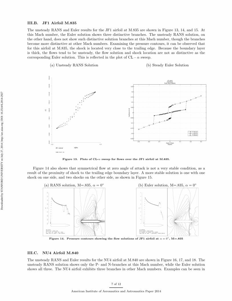
III.B. JF1 Airfoil M.835
The unsteady RANS and Euler results for the JF1 airfoil at M.835 are shown in Figure 13, 14, and 15. Atthis Mach number, the Euler solution shows three distinctive branches. The unsteady RANS solution, onthe other hand, does not show such distinctive solution branches at this Mach number, though the branchesbecome more distinctive at other Mach numbers. Examining the pressure contours, it can be observed thatfor this airfoil at M.835, the shock is located very close to the trailing edge. Because the boundary layeris thick, the flows tend to be unsteady, the flow solution and shock location are not as distinctive as thecorresponding Euler solution. This is reflected in the plot of CL - α sweep.
(a) Unsteady RANS Solution (b) Steady Euler Solution
JF1 Airfoil
GRID 384 X 128
-.2E
+00
-.2E
+00
-.1E
+00
-.5E
-01
0.0
E+
00
0.5
E-0
10.1
E+
00
0.2
E+
00
0.2
E+
00
Cl
-0.25 0.25
alpha
+++
+
++
++ +
+ ++ +
++++++++++++++
++
+
+
+
+
+
+
++
+
+++
++++
+++++++++ + + + + +
++
++
++
+
+
+
+
+
++ +
++ +
++++++++++++++++
+
+
+
+
+
+
+
++
!!"# !!"$ !!"% ! !"% !"$ !"#
!!"$&
!!"$
!!"%&
!!"%
!!"!&
!
!"!&
!"%
!"%&
!"$
!"$&
'()*+,-.,'//01234+)5++6
7-+..818+(/,-.,98./
:;%,'85.-8*!"<#&,=01>
;*-<#?,=+@>,3#<ABCA6
,
,
D!E50(1>
F!E50(1>
G!E50(1>
Figure 13. Plots of CL-α sweep for flows over the JF1 airfoil at M.835.
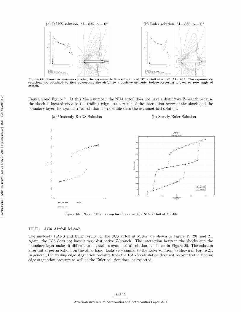
Figure 14 also shows that symmetrical flow at zero angle of attack is not a very stable condition, as aresult of the proximity of shock to the trailing edge boundary layer. A more stable solution is one with oneshock on one side, and two shocks on the other side, as shown in Figure 15.
(a) RANS solution, M=.835, α = 0◦ (b) Euler solution, M=.835, α = 0◦
JF1 Airfoil
MACH 0.835 ALPHA 0.000
CL 0.0774 CD 0.0602 CM -0.0351
GRID 384X 128 NSTEP 1 RES 0.346E+02
0.1
E+
01
0.8
E+
00
0.4
E+
00
-.2E
-15
-.4E
+00
-.8E
+00
-.1E
+01
-.2E
+01
-.2E
+01
CP
++++++++++++
+
+
+
+
+
+
+
++++++++
++
+
+
+
+
++++
+
+
+
+
+
+++++
+++++++
++++++
++++++
++++++
+++++
++++
++++
++++
+++++++++++
+
+
+
+
+
+
+
+
+
+
+
+
+
+
+++++++++
++++
+
+
+
+
+
+
+
+
+
+
+
+
+
+
++++++++++++++++++++++++++++++++++++++++++++++++++++++++++++++++++++++++
+++++++
+
+
++++++
+
+
+
+
+++++++++
JF1 AIRFOIL MACH 0.83500 ALPHA 0.00000CL 0.000000 CD 0.046047 CM 0.000000GRID 384X 64 NDES 0 RES0.568E-13 GMAX 0.100E-05
1.
2
0.8
0.
4
0.0
-0.
4 -
0.8
-1.
2 -
1.6
-2.
0
Cp
+
++++++++++++
++
+
+
+
++++++++
++++++++++++
++++++++++++++++
+++++++++++++
+++++++++
++++++++
++++++
+++++
++++
++++
++++
+
+
+
+
+
+
+
+
+
+
+
+
+++++++++++++
++++++
+
+
+
+
+
+
+
+
+
+
+
+
+++++++++++++++++++++++++++++++++++++++++++++++++++++++++++++++++++++++++++++
++++++++++++
+
+
+
++++++++++++++
+
Figure 14. Pressure contours showing the flow solutions of JF1 airfoil at α = 0◦, M=.835
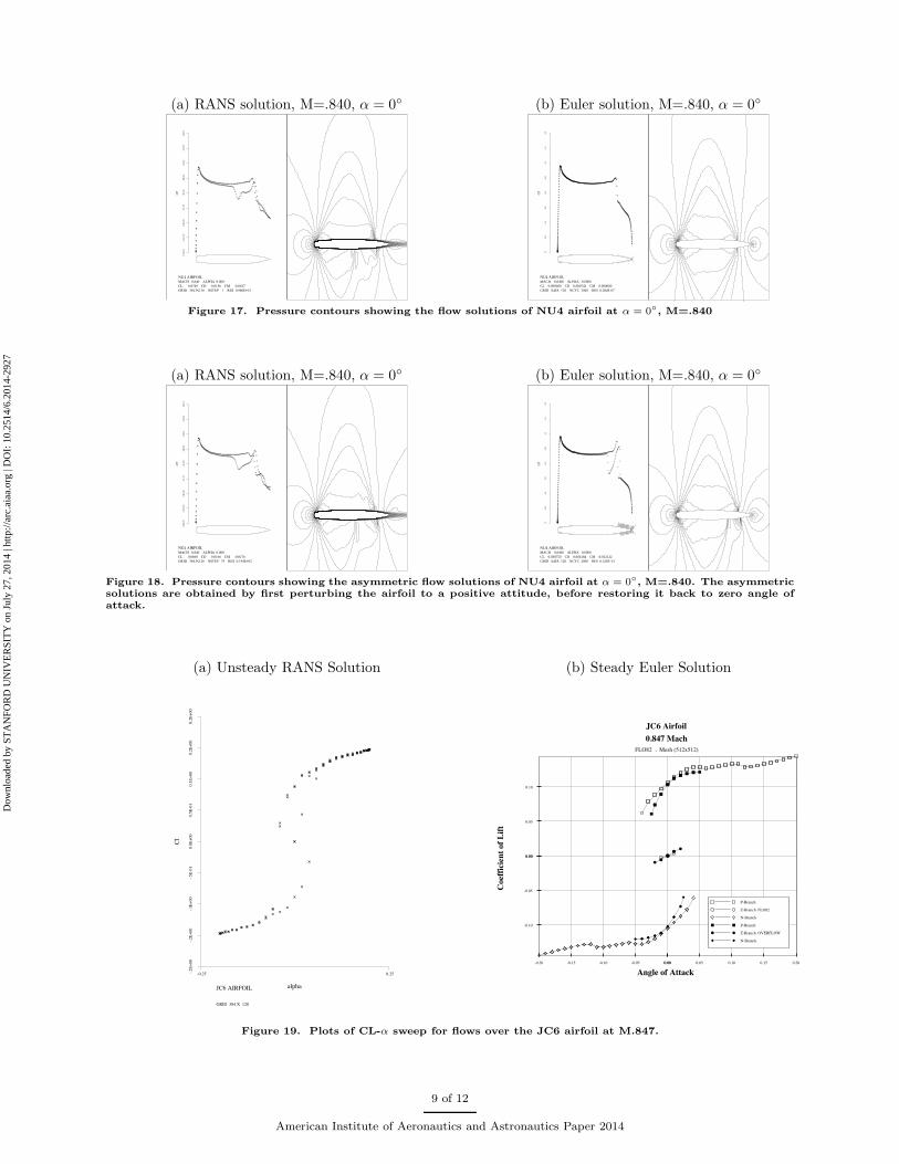
III.C. NU4 Airfoil M.840
The unsteady RANS and Euler results for the NU4 airfoil at M.840 are shown in Figure 16, 17, and 18. Theunsteady RANS solution shows only the P- and N-branches at this Mach number, while the Euler solutionshows all three. The NU4 airfoil exhibits three branches in other Mach numbers. Examples can be seen in
7 of 12
American Institute of Aeronautics and Astronautics Paper 2014
Dow
nloa
ded
by S
TA
NFO
RD
UN
IVE
RSI
TY
on
July
27,
201
4 | h
ttp://
arc.
aiaa
.org
| D
OI:
10.
2514
/6.2
014-
2927
(a) RANS solution, M=.835, α = 0◦ (b) Euler solution, M=.835, α = 0◦
JF1 Airfoil
MACH 0.835 ALPHA 0.000
CL -0.0028 CD 0.0592 CM 0.0114
GRID 384X 128 NSTEP 33 RES 0.383E+02
0.1
E+
01
0.8
E+
00
0.4
E+
00
-.2E
-15
-.4E
+00
-.8E
+00
-.1E
+01
-.2E
+01
-.2E
+01
CP
++++++
+
+
+
+
++++++++
+
+
+
+++
+
+
+
++
++++++++
++
+
+
+
+
++++
++++++
++++++++
++++++
++++++
++++
++++
++++
++++
+++++++++++
+
+
+
+
+
+
+
+
+
+
+
+
+
+
+++++++++
++++
+
+
+
+
+
+
+
+
+
+
+
+
+
+
++++++++++++++++++++++++++++++++++++++++++++++++++++++++++++++++++++++++
++++
+
+
+
+
+
++++++++++
++++
+
++++
JF1 AIRFOIL MACH 0.83500 ALPHA 0.00000CL 0.056998 CD 0.051628 CM -0.024147GRID 384X 64 NDES 0 RES0.210E-05 GMAX 0.100E-05
1.
2
0.8
0.
4
0.0
-0.
4 -
0.8
-1.
2 -
1.6
-2.
0
Cp
+
++++++++++++
+
+
+
+++++++++++++++++++++
+
+
+++++++++++
+++++++++++++
++++++++++
++++++++
++++++
++++++
++++
++++
++++++
+
+
+
+
+
+
+
+
+
+
+
+
+++++++++++++
++++++
+
+
+
+
+
+
+
+
+
+
+
+
+++++++++++++++++++++++++++++++++++++++++++++++++++++++++++++++++++++++++++++
++++++++++++
+
+
+
++++++++++++++
+
Figure 15. Pressure contours showing the asymmetric flow solutions of JF1 airfoil at α = 0◦, M=.835. The asymmetric
solutions are obtained by first perturbing the airfoil to a positive attitude, before restoring it back to zero angle ofattack.
Figure 4 and Figure 7. At this Mach number, the NU4 airfoil does not have a distinctive Z-branch becausethe shock is located close to the trailing edge. As a result of the interaction between the shock and theboundary layer, the symmetrical solution is less stable than the asymmetrical solution.
(a) Unsteady RANS Solution (b) Steady Euler Solution
NU4 AIRFOIL
GRID 384 X 128
-.2E
+00
-.2E
+00
-.1E
+00
-.5E
-01
0.0
E+
00
0.5
E-0
10.1
E+
00
0.2
E+
00
0.2
E+
00
Cl
-0.25 0.25
alpha
+
+
+ ++ + +
+ + + + + + +++++++++++++++++
++
+++
++
+
+
+++++++++++++++ + + + + + + +
+ ++ + +
++
+
+
+
+ + + + + + +++++++++++++++++
++
+++
++
!!"# !!"!$ ! !"!$ !"#!!"#
!!"!%
!!"!&
!!"!'
!!"!(
!
!"!(
!"!'
!"!&
!"!%
!"#
)*+,-./0.)1123456-+7--8
9/-00:3:-*1./0.;:01
<='.):70/:,!"%'!.>23?
@,/%(A.>-B?.5C(!D&'8
.
.
E!F72*3?
G!F72*3?
<!F72*3?
Figure 16. Plots of CL-α sweep for flows over the NU4 airfoil at M.840.
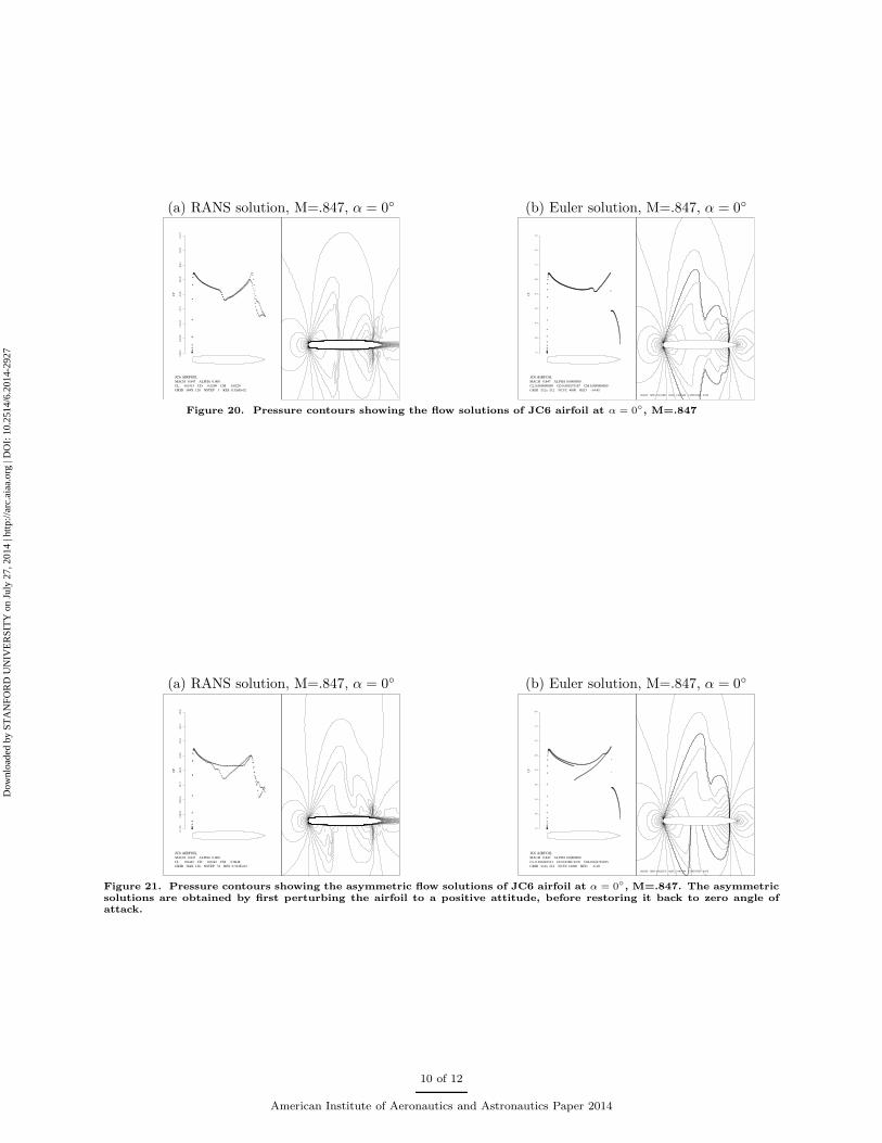
III.D. JC6 Airfoil M.847
The unsteady RANS and Euler results for the JC6 airfoil at M.847 are shown in Figure 19, 20, and 21.Again, the JC6 does not have a very distinctive Z-branch. The interaction between the shocks and theboundary layer makes it difficult to maintain a symmetrical solution, as shown in Figure 20. The solutionafter initial perturbation, on the other hand, looks very similar to the Euler solution, as shown in Figure 21.In general, the trailing edge stagnation pressure from the RANS calculation does not recover to the leadingedge stagnation pressure as well as the Euler solution does, as expected.
8 of 12
American Institute of Aeronautics and Astronautics Paper 2014
Dow
nloa
ded
by S
TA
NFO
RD
UN
IVE
RSI
TY
on
July
27,
201
4 | h
ttp://
arc.
aiaa
.org
| D
OI:
10.
2514
/6.2
014-
2927
(a) RANS solution, M=.840, α = 0◦ (b) Euler solution, M=.840, α = 0◦
NU4 AIRFOIL
MACH 0.840 ALPHA 0.000
CL 0.0749 CD 0.0156 CM -0.0187
GRID 384X 128 NSTEP 1 RES 0.986E+01
0.1
E+
01
0.8
E+
00
0.4
E+
00
-.2E
-15
-.4E
+00
-.8E
+00
-.1E
+01
-.2E
+01
-.2E
+01
CP
++++
+++++++
++++
++++
++
+
+
+
++++
++
++++++++++++++
++
++++
+
+
+++
++++++++++++++++++
+++++++++++
++++++
++++
++++
+++++++
+
+
+
+
+
+
+
+
+
+
+
++++++
+++
+
+
+
+
+
+
+
+
+
+
+++++++++++++++++++++++++++++++++++++++++++++++++++++++++++++++
+++++++++++
+++++
+
+
+
+
++++++++++++++++++
+++++
NU4 AIRFOIL MACH 0.8400 ALPHA 0.0000CL 0.000000 CD 0.000743 CM 0.000000GRID 640X 128 NCYC 2000 RES 0.384E-07
1.
2
0.8
0.
4
0.0
-0.
4 -
0.8
-1.
2 -
1.6
-2.
0
CP
+++++++++++++++++++++++++
+++++++++
+++++++++
++++++
++++++++
++
+
+
+++++++++++++++++++++++++++++++++++++++++++++++++++++++++++++++++++++++++++++++++++++++++++++++++++++++++++
++++++++++++++++++++++++++++++++++
++++++++++++++++++++
++++++++++++++++
++++++++++++++++++++++++++
+++++++++++++++++++++++++++++++++++++++++++++++++++++++++++++++++
+++++++++++++++++++++++++++++++++++++++++++++++++++++++++++++++++++++++++++++++++++++++++++++++++++++++++++++++++++++++++++++++++++++++++++++++++++++++++++++++++++++++++++++++++++++++++++++++++++++++++++++++++++++++++++++++++++
++++++++++++++++++++++++
+
+
+++++++++++++++++++++++++++++++++++++++++++++++++++++++++++
Figure 17. Pressure contours showing the flow solutions of NU4 airfoil at α = 0◦, M=.840
(a) RANS solution, M=.840, α = 0◦ (b) Euler solution, M=.840, α = 0◦
NU4 AIRFOIL
MACH 0.840 ALPHA 0.000
CL 0.0668 CD 0.0166 CM -0.0176
GRID 384X 128 NSTEP 33 RES 0.194E+02
0.1
E+
01
0.8
E+
00
0.4
E+
00
-.2E
-15
-.4E
+00
-.8E
+00
-.1E
+01
-.2E
+01
-.2E
+01
CP
+++++++++
+++++++++++
+
+
+
+++
++
++
++++++++++++++++++
++
++
+++
++++++++++++++++++
+++++++++++
++++++
++++
++++
+++++++
+
+
+
+
+
+
+
+
+
+
+
++++++
+++
+
+
+
+
+
+
+
+
+
+
+++++++++++++++++++++++++++++++++++++++++++++++++++++++++++++++++++
++++++++++
+++
+
+
+
+++++++++++
++++
++++++++
NU4 AIRFOIL MACH 0.8400 ALPHA 0.0000CL 0.038750 CD 0.004184 CM -0.012122GRID 640X 128 NCYC 2000 RES 0.320E-13
1.
2
0.8
0.
4
0.0
-0.
4 -
0.8
-1.
2 -
1.6
-2.
0
CP
++++++++++++++++++++++++
+++++++++
++++++++++
+++++++
+
+
++++++++++
+++++++++++++++++++
+
+
++++++++++++++++++++++++++++++++++++++++++++++++++++++++++++++++++++++++++++++++++++
++++++++++++++++++++++++++++++++++
+++++++++++++++++++++
++++++++++++++++
++++++++++++++++++++++++++
+++++++++++++++++++++++++++++++++++++++++++++++++++++++++++++++++
++++++++++++++++++++++++++++++++++++++++++++++++++++++++++++++++++++++++++++++++++++++++++++++++++++++++++++++++++++++++++++++++++++++++++++++++++++++++++++++++++++++++++++++++++++++++++++++++++++++++++++++++++++++++++++++++++
+++++++++++++++++++++++++++
+
+
+++++++++++++++++++++++++++++++++++++++++++++++++++++++++
Figure 18. Pressure contours showing the asymmetric flow solutions of NU4 airfoil at α = 0◦, M=.840. The asymmetric
solutions are obtained by first perturbing the airfoil to a positive attitude, before restoring it back to zero angle ofattack.
(a) Unsteady RANS Solution (b) Steady Euler Solution
JC6 AIRFOIL
GRID 384 X 128
-.2E
+00
-.2E
+00
-.1E
+00
-.5E
-01
0.0
E+
00
0.5
E-0
10.1
E+
00
0.2
E+
00
0.2
E+
00
Cl
-0.25 0.25
alpha
++
+
+
++
+ ++ + +
+ + ++++++++++++++++
++
++
+
+
+
+
++
+++++++++++++++ + + ++ + + +
++ +
+
+
+
+
+
++
+ ++ + + + +++++++++++++++
++
+++
+
+
+
+
!"!!
!"!#
!"$!
!"!!
%!"!#
%!"$!
!"!! !"!# !"$! !"$# !"&!!"!!%!"!#%!"$!%!"$#%!"&!
'()*&++,++-./0+1#$&2#$&3
!"#$%&'()&*
+,-./$0123
%45*6$)($%77128
")6((&2&647$)($=&(7
4%567890
:%567890++'()*&
;%567890
4%567890
:%567890++)<=>'()?
;%567890
Figure 19. Plots of CL-α sweep for flows over the JC6 airfoil at M.847.
9 of 12
American Institute of Aeronautics and Astronautics Paper 2014
Dow
nloa
ded
by S
TA
NFO
RD
UN
IVE
RSI
TY
on
July
27,
201
4 | h
ttp://
arc.
aiaa
.org
| D
OI:
10.
2514
/6.2
014-
2927
(a) RANS solution, M=.847, α = 0◦ (b) Euler solution, M=.847, α = 0◦
JC6 AIRFOIL
MACH 0.847 ALPHA 0.000
CL -0.0313 CD 0.0290 CM 0.0229
GRID 384X 128 NSTEP 1 RES 0.326E+02
0.1
E+
01
0.8
E+
00
0.4
E+
00
-.2E
-15
-.4E
+00
-.8E
+00
-.1E
+01
-.2E
+01
-.2E
+01
CP
++++
++++++++
++++
+
+
+
+
+++
++++
++++++++++++++++++++++++++++++++++
++
+++
++++++++
++++++
++++++
++++++
++++
++++
++++
++++
+
+
+
+
+
+
+
++++++++
+++
+
+
+
+
+
+
++++++++++++++++++++++++++++++++++++++++++++
+++
+++++
++++++
++++
++++
++++
++++
++++
+++++++++
++
+
+
+
+
+
++++++++
+++++++
JC6 AIRFOIL MACH 0.847 ALPHA 0.0000000CL 0.000000000 CD 0.009175197 CM 0.000000000 GRID 512x 512 NCYC 4000 RED -14.45
1.2
0.8
0.4
0.0
-0.4
-0.8
-1.2
-1.6
-2.0
CP
++++++++++++++++++++++++++++++++
++++++
++++++++++++
+
++++++++++++++++++++++++++++++++++++++++++++++++++++++++++++++++++++++++++++++++++++++++++++++++++++
+++++++++++++++++++++++++
+++++++++++++++++++
+++++++++++++++
++++++++++++
++++++++++++++
++
+
+
+
+
+
+
+
++++++++++++++++
+++++++
+
+
+
+
+
+
+
+++++++++++++++++++++++++++++++++++++++++++++++++++++++++++++++++++++++++++++++++++++++++++++++++++++++++++++++++++++++++++++++++++++
++++++++++++++++++++++
++++++++
++++++++
+++++++++++
+++++
+
++++++++++++++++++++++++++++++++++++++++++++++++++
MACH: MIN 0.0012867 MAX 1.3963696 CONTOURS 0.050
Figure 20. Pressure contours showing the flow solutions of JC6 airfoil at α = 0◦, M=.847
(a) RANS solution, M=.847, α = 0◦ (b) Euler solution, M=.847, α = 0◦
JC6 AIRFOIL
MACH 0.847 ALPHA 0.000
CL 0.0443 CD 0.0242 CM 0.0048
GRID 384X 128 NSTEP 33 RES 0.322E+02
0.1
E+
01
0.8
E+
00
0.4
E+
00
-.2E
-15
-.4E
+00
-.8E
+00
-.1E
+01
-.2E
+01
-.2E
+01
CP
+++
+++++
+++++
++
+
+
+
+
+
+
+++++++++++++++++++++++++++++++++++++++++
++
++
++++++
++
+++
++++++++
+++++
++++
++++
++++
++++
+++
+
+
+
+
+
+
++++++++
+++
+
+
+
+
+
+
+++++++++++++++++++++++++++++++++++++++++++++++++++++++++++++++++++++++++++
++++++
++++++
+
+
+
+
++++
+
+
+
+++++++++++
JC6 AIRFOIL MACH 0.847 ALPHA 0.0000000CL 0.105210511 CD 0.016071270 CM-0.023791015 GRID 512x 512 NCYC 12000 RED -6.18
1.2
0.8
0.4
0.0
-0.4
-0.8
-1.2
-1.6
-2.0
CP
+++++++++++++++++++++++++++++++
++++++
+++++++++++
+
++++++++++++++++++++++++++++++++++++++++++++++++++++++++++++++++++++++++++++++++++++++++++++++++++
+++++++++++++++++++++++
+++++++++++++++++++
+++++++++++++++
++++++++++++
+++++++++++
+++++++++++
+
+
+
+
+
+
+
++++++++++++++++
++++++
+
+
+
+
+
+
+
+
++++++++++++++++++++++++++++++++++++++++++++++++++++++++++++++++++++++++++++++++++++++++++++++++++++++++++++++++++++++++++++++++++++
+++++++++++++++
+++++++++++
++++++++++++++++
+++++++++++++++
+
++++++++++++++++++++++++++++++++++++++++++++++++
MACH: MIN 0.0022379 MAX 1.4407564 CONTOURS 0.050
Figure 21. Pressure contours showing the asymmetric flow solutions of JC6 airfoil at α = 0◦, M=.847. The asymmetric
solutions are obtained by first perturbing the airfoil to a positive attitude, before restoring it back to zero angle ofattack.
10 of 12
American Institute of Aeronautics and Astronautics Paper 2014
Dow
nloa
ded
by S
TA
NFO
RD
UN
IVE
RSI
TY
on
July
27,
201
4 | h
ttp://
arc.
aiaa
.org
| D
OI:
10.
2514
/6.2
014-
2927
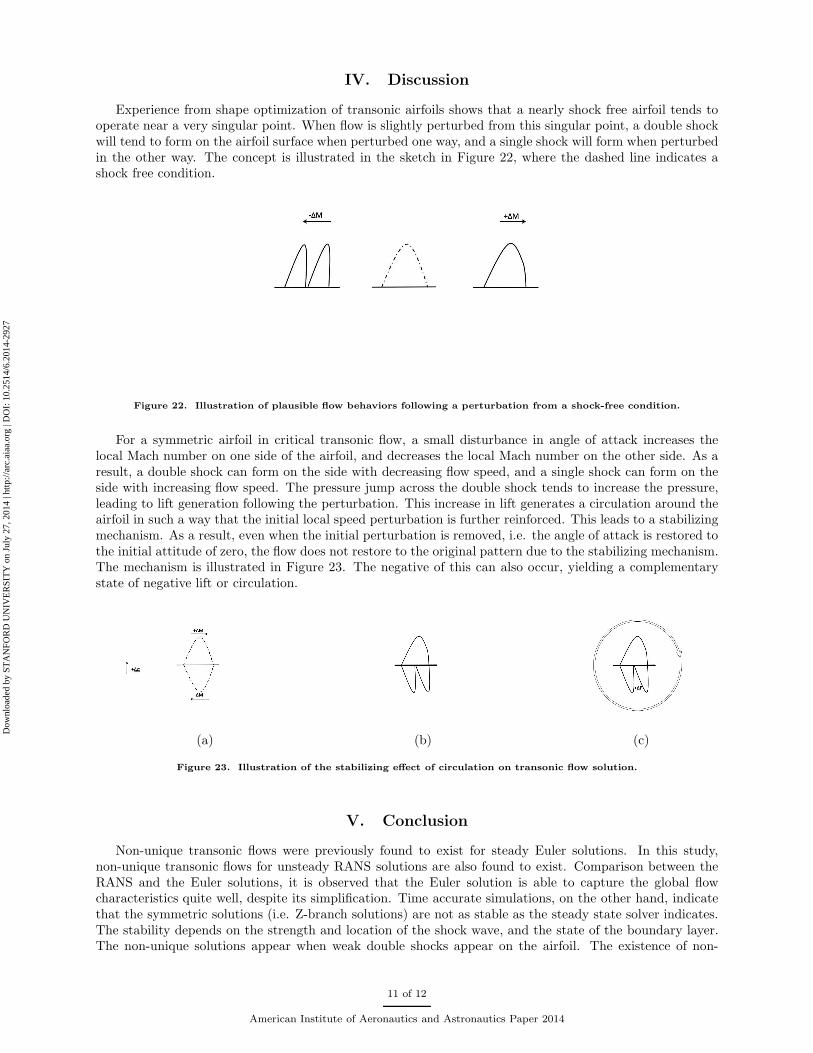
IV. Discussion
Experience from shape optimization of transonic airfoils shows that a nearly shock free airfoil tends tooperate near a very singular point. When flow is slightly perturbed from this singular point, a double shockwill tend to form on the airfoil surface when perturbed one way, and a single shock will form when perturbedin the other way. The concept is illustrated in the sketch in Figure 22, where the dashed line indicates ashock free condition.
Figure 22. Illustration of plausible flow behaviors following a perturbation from a shock-free condition.
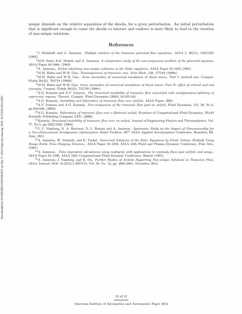
For a symmetric airfoil in critical transonic flow, a small disturbance in angle of attack increases thelocal Mach number on one side of the airfoil, and decreases the local Mach number on the other side. As aresult, a double shock can form on the side with decreasing flow speed, and a single shock can form on theside with increasing flow speed. The pressure jump across the double shock tends to increase the pressure,leading to lift generation following the perturbation. This increase in lift generates a circulation around theairfoil in such a way that the initial local speed perturbation is further reinforced. This leads to a stabilizingmechanism. As a result, even when the initial perturbation is removed, i.e. the angle of attack is restored tothe initial attitude of zero, the flow does not restore to the original pattern due to the stabilizing mechanism.The mechanism is illustrated in Figure 23. The negative of this can also occur, yielding a complementarystate of negative lift or circulation.
(a) (b) (c)
Figure 23. Illustration of the stabilizing effect of circulation on transonic flow solution.
V. Conclusion
Non-unique transonic flows were previously found to exist for steady Euler solutions. In this study,non-unique transonic flows for unsteady RANS solutions are also found to exist. Comparison between theRANS and the Euler solutions, it is observed that the Euler solution is able to capture the global flowcharacteristics quite well, despite its simplification. Time accurate simulations, on the other hand, indicatethat the symmetric solutions (i.e. Z-branch solutions) are not as stable as the steady state solver indicates.The stability depends on the strength and location of the shock wave, and the state of the boundary layer.The non-unique solutions appear when weak double shocks appear on the airfoil. The existence of non-
11 of 12
American Institute of Aeronautics and Astronautics Paper 2014
Dow
nloa
ded
by S
TA
NFO
RD
UN
IVE
RSI
TY
on
July
27,
201
4 | h
ttp://
arc.
aiaa
.org
| D
OI:
10.
2514
/6.2
014-
2927
unique depends on the relative separation of the shocks, for a given perturbation. An initial perturbationthat is significant enough to cause the shocks to interact and coalesce is more likely to lead to the creationof non-unique solutions.
References
1J. Steinhoff, and A. Jameson, Multiple solution of the transonic potential flow equations, AIAA J. 20(11), 15211525(1982)
2M.D. Salas, R.E. Melnik, and A. Jameson, A comparative study of the non-uniqueness problem of the potential equation,AIAA Paper 83-1888, (1983)
3A. Jameson, Airfoil admitting non-unique solutions to the Euler equations, AIAA Paper 91-1625 (1991)4M.M. Hafez and W.H. Guo, Nonuniqueness of transonic ows, Acta Mech. 138, 177184 (1999a)5M.M. Hafez and W.H. Guo, Some anomalies of numerical simulation of shock waves, Part I: inviscid ows. Comput.
Fluids 28(45), 701719 (1999b)6M.M. Hafez and W.H. Guo, Some anomalies of numerical simulation of shock waves. Part II: effect of articial and real
viscosity, Comput. Fluids 28(45), 721739 (1999c)7A.G. Kuzmin and A.V. Ivanova, The structural instability of transonic flow associated with amalgamation/splitting of
supersonic regions, Theoret. Comput. Fluid Dynamics (2004) 18:335-3448A.G. Kuzmin, Instability and bifurcation of transonic flow over airfoils, AIAA Paper, 20049A.V. Ivanova and A.G. Kuzmin, Non-uniqueness of the transonic flow past an airfoil, Fluid Dynamics, Vol. 39, No.4,
pp.642-648, (2004)10A.G. Kuzmin, Bifurcation of transonic flow over a flattened airfoil, Frontiers of Computational Fluid Dynamics, World
Scientific Publishing Company LTD, (2006)11Kuzmin, Structural instability of transonic flow over an airfoil, Journal of Engineering Physics and Thermophysics, Vol.
77, No.5, pp.1022-1026, (2004)12J. C. Vassberg, N. A. Harrison, D. L. Roman and A. Jameson, Systematic Study on the Impact of Dimensionality for
a Two-Dimensional Aerodynamic Optimization Model Problem, 29th AIAA Applied Aerodynamics Conference, Honolulu, HI,June, 2011
13A. Jameson, W. Schmidt, and E. Turkel, Numerical Solutions of the Euler Equations by Finite Volume Methods UsingRunge-Kutta Time-Stepping Schemes, AIAA Paper 81-1259, AIAA 14th Fluid and Plasma Dynamic Conference, Palo Alto,(1981)
14A. Jameson, .Time dependent calculations using multigrid, with applications to unsteady flows past airfoils and wings.,AIAA Paper 91-1596, AIAA 10th Computational Fluid Dynamic Conference, Hawaii (1991).
15A. Jameson, J. Vassberg, and K. Ou, Further Studies of Airfoils Supporting Non-unique Solutions in Transonic Flow,AIAA Journal, DOI: 10.2514/1.J051713, Vol. 50, No. 12, pp. 2865-2881, December 2012.
12 of 12
American Institute of Aeronautics and Astronautics Paper 2014
Dow
nloa
ded
by S
TA
NFO
RD
UN
IVE
RSI
TY
on
July
27,
201
4 | h
ttp://
arc.
aiaa
.org
| D
OI:
10.
2514
/6.2
014-
2927


![[Mason] transonic aerodynamics of airfoils and wings](https://img.pdfslide.net/doc/110x75/554a2d19b4c9051b578b4ef9/mason-transonic-aerodynamics-of-airfoils-and-wings.jpg)