Embed Size (px)
Citation preview

1
SNMP-GSH2804L
24 Port Gigabit + 4-Port UTP/SFP Web Smart Switch
User Manual

Copyright and Disclaimer
AirLive SNMP-GSH2804L User Manual i
Copyright & Disclaimer No part of this publication may be reproduced in any form or by any means, whether electronic, mechanical, photocopying, or recording without the written consent of OvisLink Corp. OvisLink Corp. has made the best effort to ensure the accuracy of the information in this user’s guide. However, we are not liable for the inaccuracies or errors in this guide. Please use with caution. All information is subject to change without notice All Trademarks are properties of their respective holders.
Copyright and Disclaimer
AirLive SNMP-GSH2804L User Manual ii
FCC Statement Federal Communication Commission Interference Statement This equipment has been tested and found to comply with the limits for a Class B digital device, pursuant to Part 15 of the FCC Rules. These limits are designed to provide reasonable protection against harmful interference in a residential installation. This equipment generates uses and can radiate radio frequency energy and, if not installed and used in accordance with the instructions, may cause harmful interference to radio communications. However, there is no guarantee that interference will not occur in a particular installation. If this equipment does cause harmful interference to radio or television reception, which can be determined by turning the equipment off and on, the user is encouraged to try to correct the interference by one of the following measures: Reorient or relocate the receiving antenna. Increase the separation between the equipment and receiver. Connect the equipment into an outlet on a circuit different from that to which the
receiver is connected. Consult the dealer or an experienced radio/TV technician for help. FCC Caution Any changes or modifications not expressly approved by the party responsible for compliance could void the user's authority to operate this equipment. This device complies with Part 15 of the FCC Rules. Operation is subject to the following two conditions: (1) This device may not cause harmful interference, and (2) this device must accept any interference received, including interference that may cause undesired operation. For product available in the USA/Canada market, only channel 1~11 can be operated. Selection of other channels is not possible. This device and its antenna(s) must not be co-located or operation in conjunction with any other antenna or transmitter. IMPORTANT NOTE FCC Radiation Exposure Statement: This equipment complies with FCC radiation exposure limits set forth for an uncontrolled environment. This equipment should be installed and operated with minimum distance 20cm between the radiator & your body.
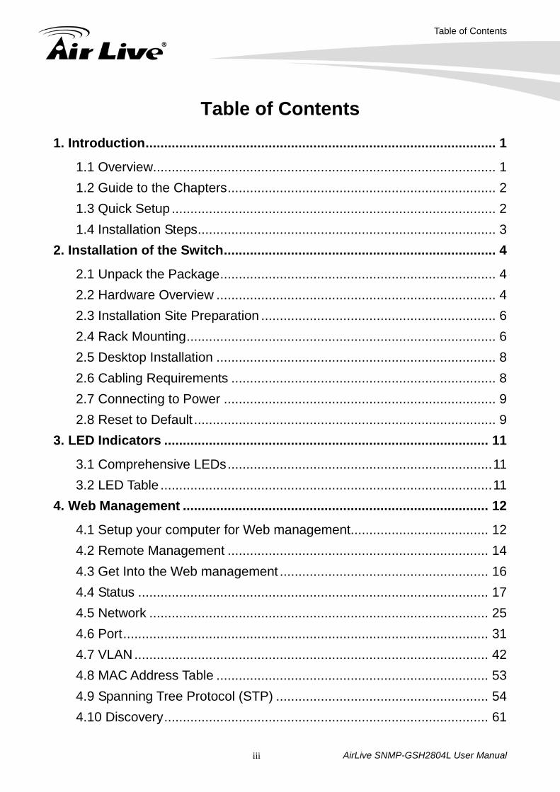
Table of Contents
AirLive SNMP-GSH2804L User Manual iii
Table of Contents 1. Introduction .............................................................................................. 1
1.1 Overview............................................................................................ 1
1.2 Guide to the Chapters ........................................................................ 2
1.3 Quick Setup ....................................................................................... 2
1.4 Installation Steps ................................................................................ 3
2. Installation of the Switch ......................................................................... 4
2.1 Unpack the Package .......................................................................... 4
2.2 Hardware Overview ........................................................................... 4
2.3 Installation Site Preparation ............................................................... 6
2.4 Rack Mounting ................................................................................... 6
2.5 Desktop Installation ........................................................................... 8
2.6 Cabling Requirements ....................................................................... 8
2.7 Connecting to Power ......................................................................... 9
2.8 Reset to Default ................................................................................. 9
3. LED Indicators ....................................................................................... 11
3.1 Comprehensive LEDs ....................................................................... 11
3.2 LED Table ......................................................................................... 11
4. Web Management .................................................................................. 12
4.1 Setup your computer for Web management..................................... 12
4.2 Remote Management ...................................................................... 14
4.3 Get Into the Web management ........................................................ 16
4.4 Status .............................................................................................. 17
4.5 Network ........................................................................................... 25
4.6 Port .................................................................................................. 31
4.7 VLAN ............................................................................................... 42
4.8 MAC Address Table ......................................................................... 53
4.9 Spanning Tree Protocol (STP) ......................................................... 54
4.10 Discovery ....................................................................................... 61
Table of Contents
AirLive SNMP-GSH2804L User Manual iv
4.11 Multicast ......................................................................................... 73
4.12 Security.......................................................................................... 82
4.13 QoS ............................................................................................... 90
4.14 Diagnostics ...................................................................................103
4.15 Management .................................................................................108
4.16 SNMP ........................................................................................... 115
5. Specifications .......................................................................................118
1. Introduction
AirLive SNMP-GSH2804L User Manual 1
1 1. Introduction
1.1 Overview
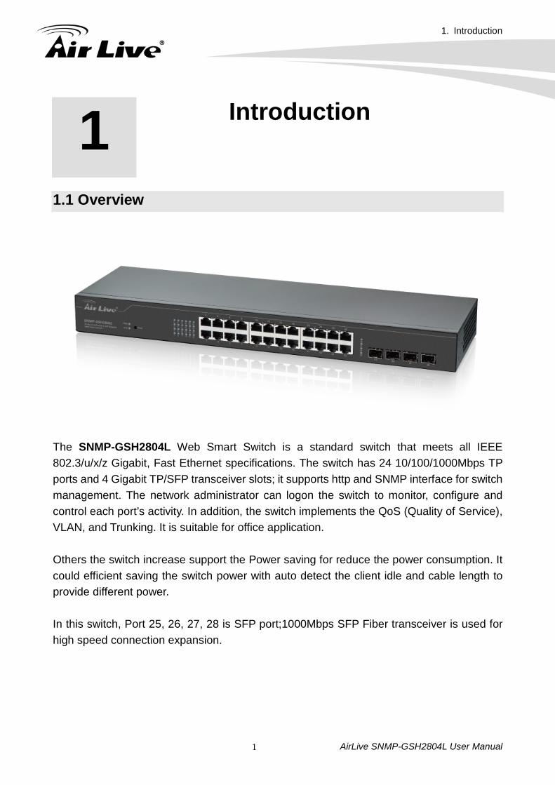
The SNMP-GSH2804L Web Smart Switch is a standard switch that meets all IEEE 802.3/u/x/z Gigabit, Fast Ethernet specifications. The switch has 24 10/100/1000Mbps TP ports and 4 Gigabit TP/SFP transceiver slots; it supports http and SNMP interface for switch management. The network administrator can logon the switch to monitor, configure and control each port’s activity. In addition, the switch implements the QoS (Quality of Service), VLAN, and Trunking. It is suitable for office application. Others the switch increase support the Power saving for reduce the power consumption. It could efficient saving the switch power with auto detect the client idle and cable length to provide different power. In this switch, Port 25, 26, 27, 28 is SFP port;1000Mbps SFP Fiber transceiver is used for high speed connection expansion.
1. Introduction
AirLive SNMP-GSH2804L User Manual 2
- 1000Mbps LC, Multi-Mode, SFP Fiber transceiver - 1000Mbps LC, Single-Mode, SFP Fiber transceiver, 10km - 1000Mbps LC, Single-Mode, SFP Fiber transceiver, 30km - 1000Mbps LC, Single-Mode, SFP Fiber transceiver, 50km - 100Mbps LC, Multi-Mode, SFP Fiber transceiver, 2km - 100Mbps LC, Single-Mode, SFP Fiber transceiver, 30km This user manual will help you to uncover most functions of the SNMP-GSH2804L with step-by-step instructions presented by high quality illustrations. Thank you for choosing OvisLink’s product.
1.2 Guide to the Chapters Chapter 1: Introduction and Quick Setup guide. All the essential information including
IP Address and Password information are in the Quick Setup section. Chapter 2: Detail installation instruction. Chapter 3: LED indicators Chapter 4: Detail information on Web management including how to setup remote
management.
1.3 Quick Setup This section provides the essential information for experienced users to operate the switch immediately. For detailed installation instruction, please see chapter 2 for more information. Power-On the switch The SNMP-GSH2804L has a built-in power supply to operate with 100 ~ 240V AC, 50 ~
60Hz power source. The AC power cord connector is located at the rear of the unit After the Switch is powered on, it will perform “self-diagnostic” test. This process takes
about 30 seconds to complete.
Important Information
The default IP address: 192.168.2.1 The default password is airlive
1. Introduction
AirLive SNMP-GSH2804L User Manual 3
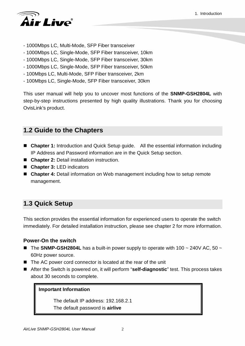
LED Table
LED Color/Status Description Power Green Power on
System Green On The switch is on Green Blinking The switch is rebooting
Link/ACT Green On Link 1000/100Mbps Green Blinking Link Up
1.4 Installation Steps This section lists the installation procedures in steps. Each step’s instruction is thoroughly explained in the subsequent sections of following chapter.
Step1. Connect your PC to the switch. Step2. Set your PC's IP address to 192.168.2.50.
Step3. Open your web browser and enter "192.168.2.1" to get into the switch's web
management.
Step4. Enter "admin" for username and "airlive" for password.
Step5. If you want to install the switch on the 19" rack, please install the mounting kit.
Step6. Please see the following chapters for further configurations.
2. Installation of the Switch
AirLive SNMP-GSH2804L User Manual 4
2 2. Installation of the Switch
This chapter provides the detailed instructions for installation of the switch. For concise installation instruction, the previous chapter’s “Quick Setup” section provides all the important information including IP address, password, and LED table for user’s reference.
2.1 Unpack the Package Before you begin the installation of SNMP-GSH2804L Web smart Switch, make sure that you have all the necessary accessories that come with your package. Follow the steps below to unpack your package contents: 1. Clear out an adequate space to unpack the package carton. 2. Open the package carton and take out the contents carefully. 3. Put back all the shipping materials such as plastic bag, padding and linings into the package carton and save them for future transport need. After unpacking and taking out the entire package contents, you should check whether you have got the following items: SNMP-GSH2804L One AC Power Cord Quick Installation Guide Support CD-ROM (The PDF version of this User’s Manual can be found within CD) One Pair Rack-mount Kit + 8 Screws If any of these above items is missing or damaged, please contact your local dealer for replacement. 2.2 Hardware Overview 2.2.1. Front Panel The front panel of the web smart switch consists of 24 10/100/1000M Base-TX RJ-45 ports and 4 100/1000M SFP ports. The LED Indicators are also located on the front panel.
2. Installation of the Switch
AirLive SNMP-GSH2804L User Manual 5
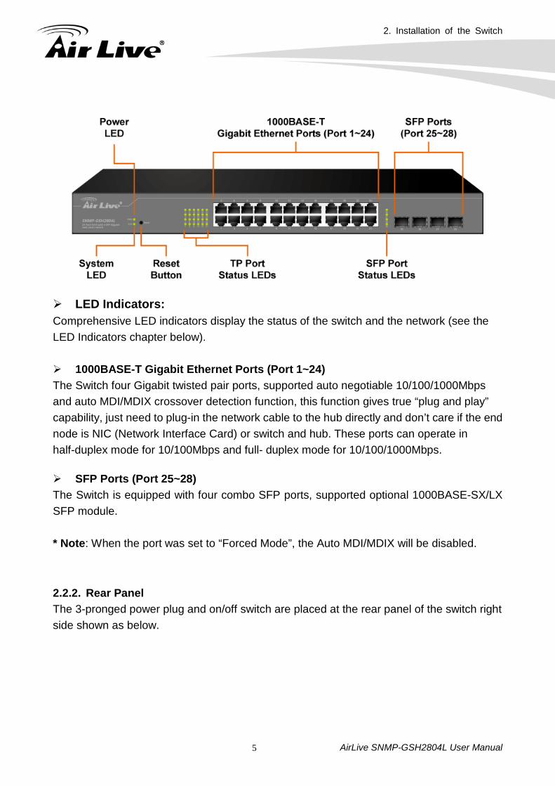
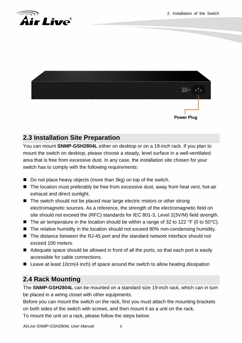
LED Indicators: Comprehensive LED indicators display the status of the switch and the network (see the LED Indicators chapter below). 1000BASE-T Gigabit Ethernet Ports (Port 1~24) The Switch four Gigabit twisted pair ports, supported auto negotiable 10/100/1000Mbps and auto MDI/MDIX crossover detection function, this function gives true “plug and play” capability, just need to plug-in the network cable to the hub directly and don’t care if the end node is NIC (Network Interface Card) or switch and hub. These ports can operate in half-duplex mode for 10/100Mbps and full- duplex mode for 10/100/1000Mbps. SFP Ports (Port 25~28) The Switch is equipped with four combo SFP ports, supported optional 1000BASE-SX/LX SFP module. * Note: When the port was set to “Forced Mode”, the Auto MDI/MDIX will be disabled. 2.2.2. Rear Panel The 3-pronged power plug and on/off switch are placed at the rear panel of the switch right side shown as below.
2. Installation of the Switch
AirLive SNMP-GSH2804L User Manual 6
2.3 Installation Site Preparation You can mount SNMP-GSH2804L either on desktop or on a 19-inch rack. If you plan to mount the switch on desktop, please choose a steady, level surface in a well-ventilated area that is free from excessive dust. In any case, the installation site chosen for your switch has to comply with the following requirements: Do not place heavy objects (more than 3kg) on top of the switch. The location must preferably be free from excessive dust, away from heat vent, hot-air
exhaust and direct sunlight. The switch should not be placed near large electric motors or other strong
electromagnetic sources. As a reference, the strength of the electromagnetic field on site should not exceed the (RFC) standards for IEC 801-3, Level 2(3V/M) field strength.
The air temperature in the location should be within a range of 32 to 122 °F (0 to 50°C). The relative humidity in the location should not exceed 90% non-condensing humidity. The distance between the RJ-45 port and the standard network interface should not
exceed 100 meters. Adequate space should be allowed in front of all the ports, so that each port is easily
accessible for cable connections. Leave at least 10cm(4 inch) of space around the switch to allow heating dissipation
2.4 Rack Mounting The SNMP-GSH2804L can be mounted on a standard size 19-inch rack, which can in turn be placed in a wiring closet with other equipments. Before you can mount the switch on the rack, first you must attach the mounting brackets on both sides of the switch with screws, and then mount it as a unit on the rack. To mount the unit on a rack, please follow the steps below:
2. Installation of the Switch
AirLive SNMP-GSH2804L User Manual 7
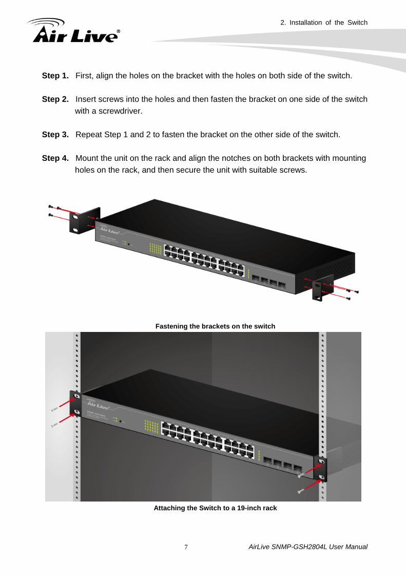
Step 1. First, align the holes on the bracket with the holes on both side of the switch.
Step 2. Insert screws into the holes and then fasten the bracket on one side of the switch with a screwdriver.
Step 3. Repeat Step 1 and 2 to fasten the bracket on the other side of the switch.
Step 4. Mount the unit on the rack and align the notches on both brackets with mounting
holes on the rack, and then secure the unit with suitable screws.
Fastening the brackets on the switch
Attaching the Switch to a 19-inch rack
2. Installation of the Switch
AirLive SNMP-GSH2804L User Manual 8
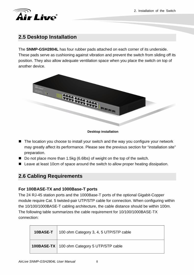
2.5 Desktop Installation The SNMP-GSH2804L has four rubber pads attached on each corner of its underside. These pads serve as cushioning against vibration and prevent the switch from sliding off its position. They also allow adequate ventilation space when you place the switch on top of another device.
Desktop installation
The location you choose to install your switch and the way you configure your network
may greatly affect its performance. Please see the previous section for “installation site” preparation.
Do not place more than 1.5kg (6.6lbs) of weight on the top of the switch. Leave at least 10cm of space around the switch to allow proper heating dissipation.
2.6 Cabling Requirements For 100BASE-TX and 1000Base-T ports The 24 RJ-45 station ports and the 1000Base-T ports of the optional Gigabit-Copper module require Cat. 5 twisted-pair UTP/STP cable for connection. When configuring within the 10/100/1000BASE-T cabling architecture, the cable distance should be within 100m. The following table summarizes the cable requirement for 10/100/1000BASE-TX connection:
10BASE-T 100 ohm Category 3, 4, 5 UTP/STP cable
100BASE-TX 100 ohm Category 5 UTP/STP cable
2. Installation of the Switch
AirLive SNMP-GSH2804L User Manual 9
1000BASE-T 100 ohm Category 5 UTP/STP cable or better (CAT 5E recommended)
Auto MDI/MDI-X function The SNMP-GSH2804L is equipped with Auto-MDI/MDI-X function, which allows you to use straight-through cable even when connecting to another switch/hub. Simply use the straight-through cable for all types of 10/100BASE-TX connections, either to a PC or to a networking device such as other hub or switch.
10 /100Base-TX and 1000Base-TPorts
Interface RJ-45 Cable to Use To an end station Straight-through twisted-pair cable To a hub/switch Straight-through twisted-pair cable Maximum Distance 100 meters
Cabling type for 10/100BASE-TX and 1000Base-T
2.7 Connecting to Power SNMP-GSH2804L features a universal auto-select power supply unit, which allows a power connection to a wide range of input voltages from 100 to 240VAC @ 50 ~ 60Hz. To establish its power connection, simply plug the female end of the power cord into the power connector on the rear of the switch and the male end of the power cord into a suitable power outlet. Once you have correctly plugged in the power, you can then turn on the Power Switch to activate the switch.
2.8 Reset to Default When you forgot your IP or password, please use the reset button for the factory default setting. Please take the following steps to reset the Web Smart Switch back to the original default:
Step 1. Turn on the SNMP-GSH2804L. Step 2. Press and hold the reset button continuously for 10 seconds and release
the resetbutton.
Connection Specification
2. Installation of the Switch
AirLive SNMP-GSH2804L User Manual 10
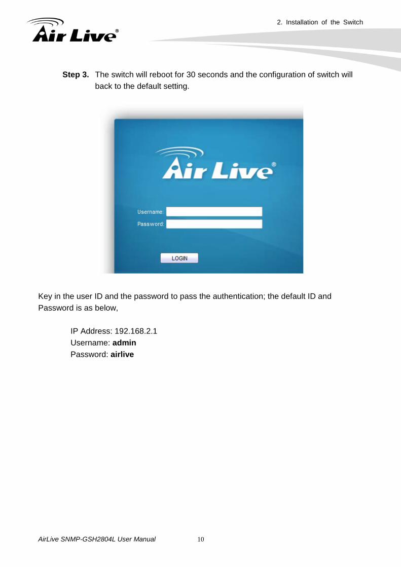
Step 3. The switch will reboot for 30 seconds and the configuration of switch will back to the default setting.
Key in the user ID and the password to pass the authentication; the default ID and Password is as below,
IP Address: 192.168.2.1 Username: admin Password: airlive
3. LED Indicators
AirLive SNMP-GSH2804L User Manual 11
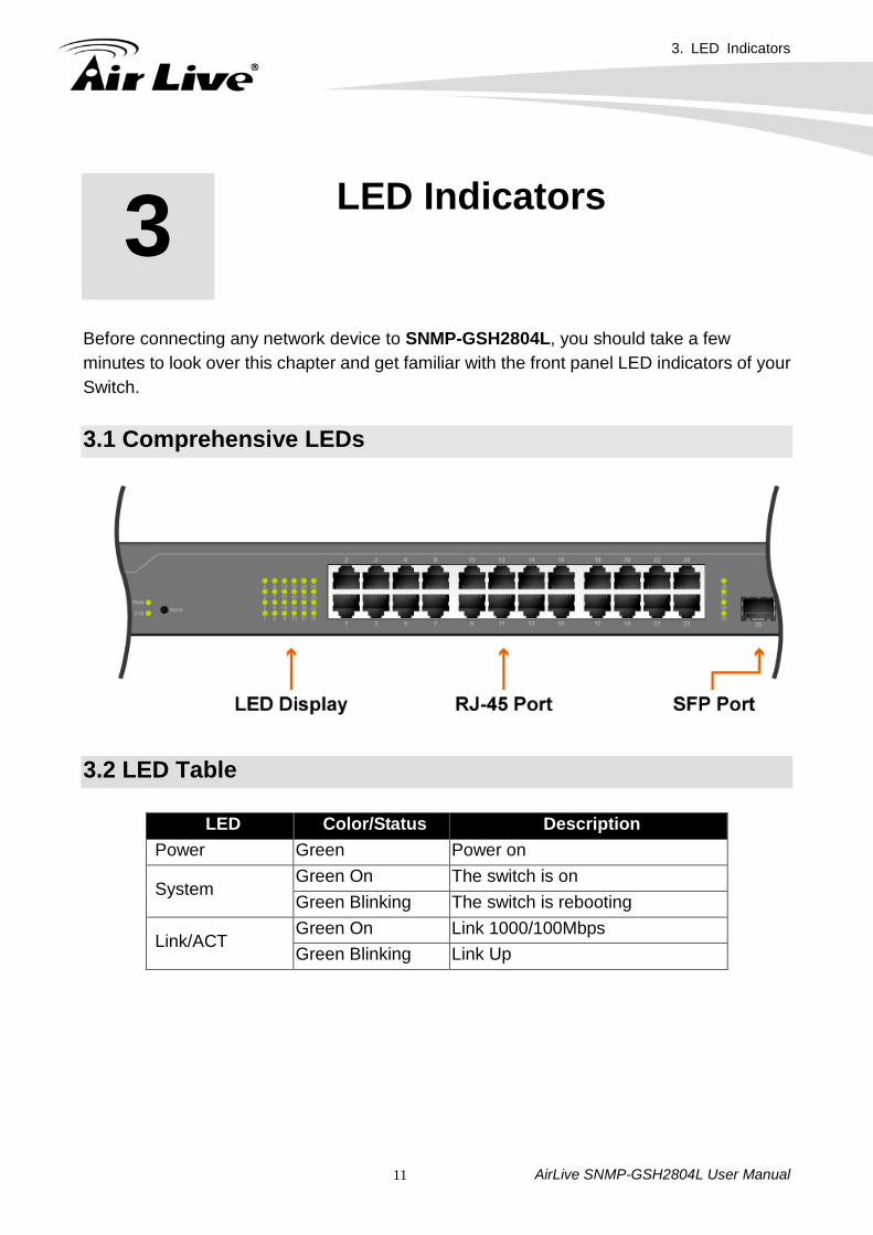
Before connecting any network device to SNMP-GSH2804L, you should take a few minutes to look over this chapter and get familiar with the front panel LED indicators of your Switch. 3.1 Comprehensive LEDs
3.2 LED Table
LED Color/Status Description Power Green Power on
System Green On The switch is on Green Blinking The switch is rebooting
Link/ACT Green On Link 1000/100Mbps Green Blinking Link Up
3 3. LED Indicators
4. Web Management
AirLive SNMP-GSH2804L User Manual 12
The SNMP-GSH2804L can be configured by web based interface, including System Information, Ports Configuration, VLAN setting, Aggregation, QoS setting, IGMP Snooping, Mirroring, SNMP, Loop Detection, Broadcast Strom, configuration/ backup/recovery, log out, and so on. The device based smart switch supports main stream browsers, such as IE, Firefox and Chrome…etc to configure the device function. All functions are illustrated below.
4.1 Setup your computer for Web management The Concept of Subnet Under the TCP/IP environment, network devices must be on the same subnet in order to see each other. This means before you can configure the switch through web browser, you must set your computer to the same subnet as the switch. For two network devices to be on the same subnet, they must have the following 2 criteria:
Their IP address must be on the same subnet. For example, if one IP address is
192.168.2.1. The other’s IP address must be 192.168.2.x (x is any number between 2 and 254) for Class C subnet. To find out the IP address information for your computer. Under WinXP/Vista/Win7/Win8, please open Command Line window and type “ipconfig”.
They must have the same subnet mask. For example, if one machine is 255.255.255.0. The other machine must also set to the same 255.255.255.0 mask.
Configure your computer’s IP Before accessing the switch through web browser, please follow the instruction below to configure your computer’s IP to the same subnet as the switch. If your switch’s IP has not been changed, it should have the following factory default value: The switch’s Default IP
IP Address: 192.168.2.1 Subnet Mask: 255.255.255.0
4 4. Web Management
4. Web Management
AirLive SNMP-GSH2804L User Manual 13
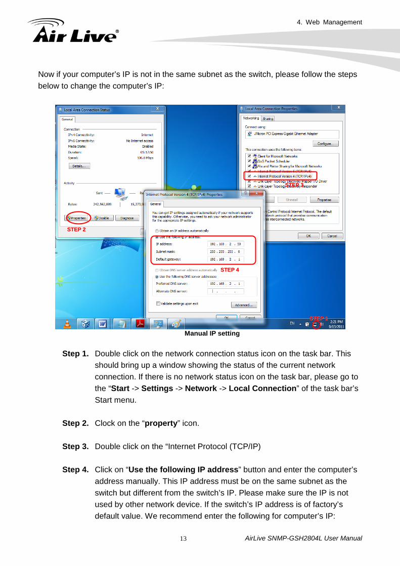
Now if your computer’s IP is not in the same subnet as the switch, please follow the steps below to change the computer’s IP:
Manual IP setting Step 1. Double click on the network connection status icon on the task bar. This
should bring up a window showing the status of the current network connection. If there is no network status icon on the task bar, please go to the “Start -> Settings -> Network -> Local Connection” of the task bar’s Start menu.
Step 2. Clock on the “property” icon.
Step 3. Double click on the “Internet Protocol (TCP/IP)
Step 4. Click on “Use the following IP address” button and enter the computer’s
address manually. This IP address must be on the same subnet as the switch but different from the switch’s IP. Please make sure the IP is not used by other network device. If the switch’s IP address is of factory’s default value. We recommend enter the following for computer’s IP:
SSTTEEPP 22
SSTTEEPP 33
SSTTEEPP 11
SSTTEEPP 44
4. Web Management
AirLive SNMP-GSH2804L User Manual 14
IP Address: 192.168.2.50 Subnet Mask: 255.255.255.0 Gateway: 192.168.2.1
Click “Ok” after finish entering the IP. * Note: The SNMP-GSH2804L has DHCP client ability. This allows DHCP server (or router) to assign IP automatically. However, we do not recommend turning on the DHCP client because the DHCP server assign the IP randomly. The DHCP client should be used only when connecting directly to Cable Modem (for remote management) whose service provider uses DHCP for IP assignment. Now, you will be able to access the switch by typing in the switch’s IP address on the web browser.
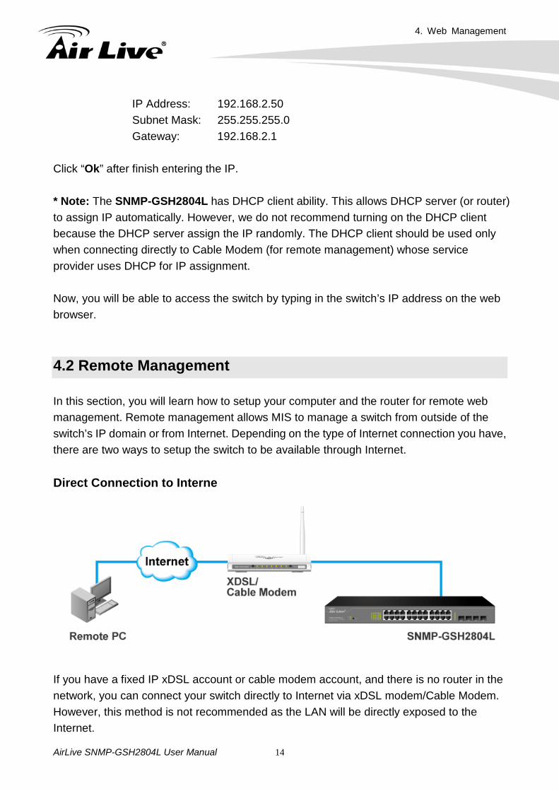
4.2 Remote Management In this section, you will learn how to setup your computer and the router for remote web management. Remote management allows MIS to manage a switch from outside of the switch’s IP domain or from Internet. Depending on the type of Internet connection you have, there are two ways to setup the switch to be available through Internet. Direct Connection to Interne
If you have a fixed IP xDSL account or cable modem account, and there is no router in the network, you can connect your switch directly to Internet via xDSL modem/Cable Modem. However, this method is not recommended as the LAN will be directly exposed to the Internet.
4. Web Management
AirLive SNMP-GSH2804L User Manual 15
Fixed IP: If your ISP has assigned you a fixed IP. Please go to the Switch’s IP configuration and enter the IP address, Subnet Mask, and Gateway information offered by your ISP. If your ADSL connection is PPPoE or PPTP type, you have to connect through a router for remote management.
Cable Modem: If your Cable service provider uses DHCP for IP assignment, please
turn on the DHCP function under IP configuration. Make sure there is no DHCP server in the network. Then the Cable provider will assign the switch with a IP and Gateway. Go to the console port management to find out what IP has been assigned to the switch.
When the configuration is finished, the Remote PC can access the switch by typing the switch’s IP address on the web browser.
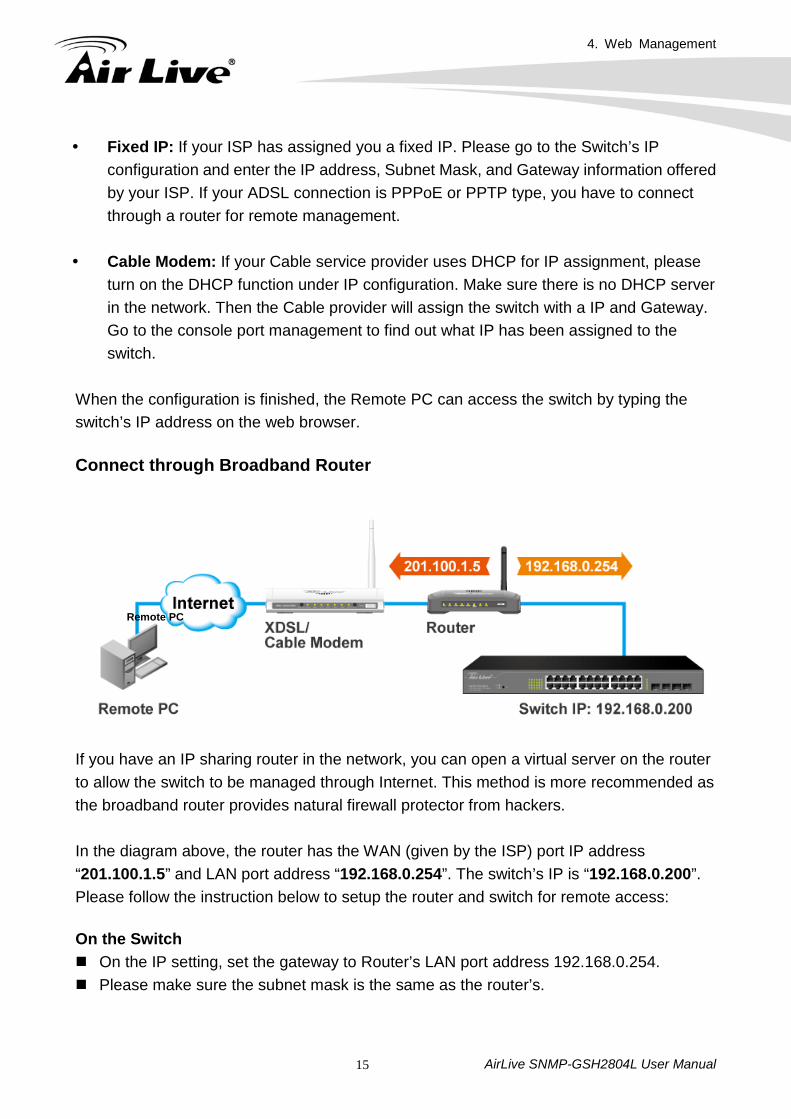
Connect through Broadband Router
If you have an IP sharing router in the network, you can open a virtual server on the router to allow the switch to be managed through Internet. This method is more recommended as the broadband router provides natural firewall protector from hackers. In the diagram above, the router has the WAN (given by the ISP) port IP address “201.100.1.5” and LAN port address “192.168.0.254”. The switch’s IP is “192.168.0.200”. Please follow the instruction below to setup the router and switch for remote access:
On the Switch On the IP setting, set the gateway to Router’s LAN port address 192.168.0.254. Please make sure the subnet mask is the same as the router’s.
Remote PC
4. Web Management
AirLive SNMP-GSH2804L User Manual 16
On the Router Go to router’s Virtual Server setting and open the Web port (TCP Port 80) to the switch’s
IP address 192.168.0.200. If your router require enter the beginning and ending Port (from PortX to PortX), enter
80 for both. Now the Remote PC will be able to access your switch by entering “201.100.1.5” in the Web browser’s address field. 4.3 Get Into the Web management After you have properly configured the computer and switch’s IP, you can get into the web management by the following steps:
Step 1. Open the Internet Explorer Step 2. Enter the switch’s IP address in the Address field and press enter. Step 3. When prompt for User name and Password, enter the following information:
User name: admin Password: airlive
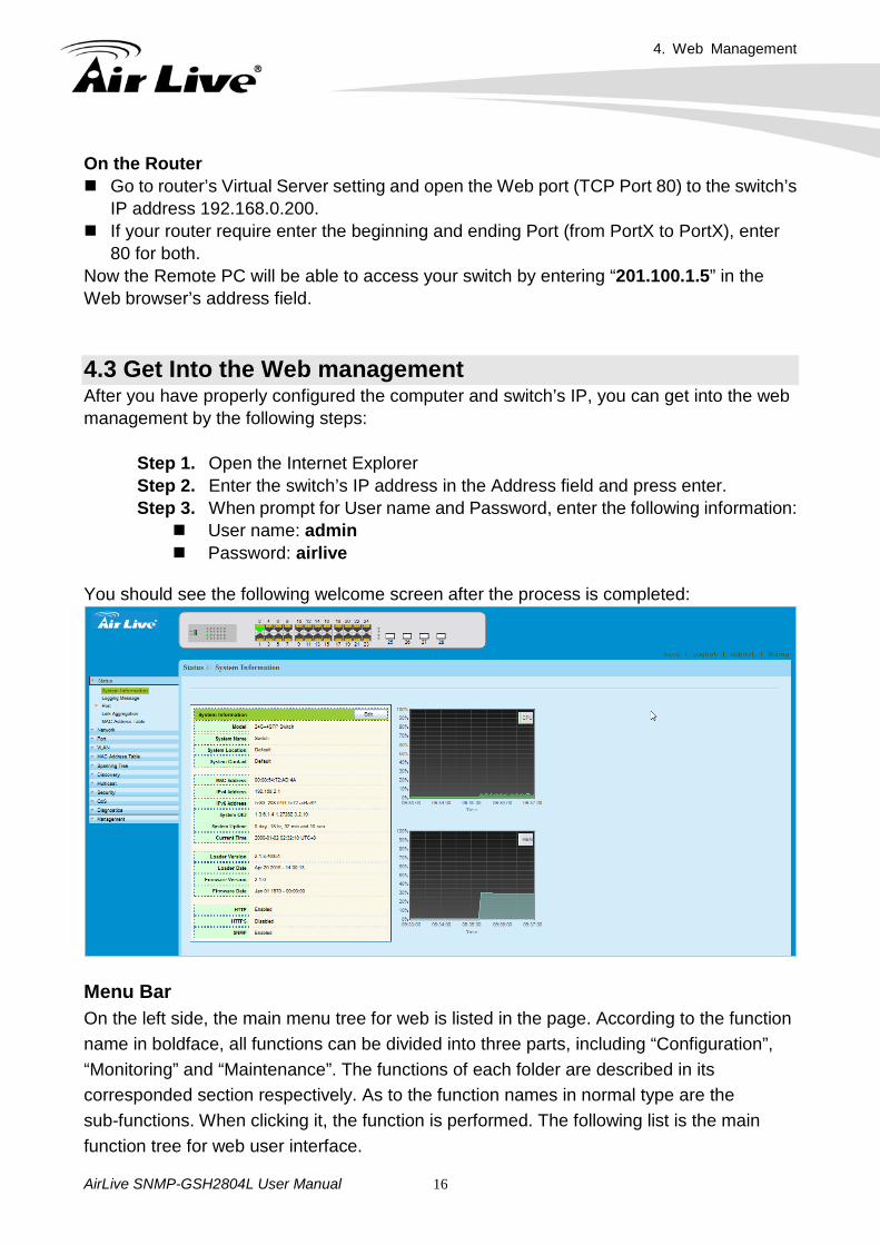
You should see the following welcome screen after the process is completed:
Menu Bar On the left side, the main menu tree for web is listed in the page. According to the function name in boldface, all functions can be divided into three parts, including “Configuration”, “Monitoring” and “Maintenance”. The functions of each folder are described in its corresponded section respectively. As to the function names in normal type are the sub-functions. When clicking it, the function is performed. The following list is the main function tree for web user interface.
4. Web Management
AirLive SNMP-GSH2804L User Manual 17
Top Switch Image The switch’s image on the upper portion of the screen gives the quick overview of the port connection status. When a port is plugged in, the switch’s image will show a “plug” on the corresponding port.
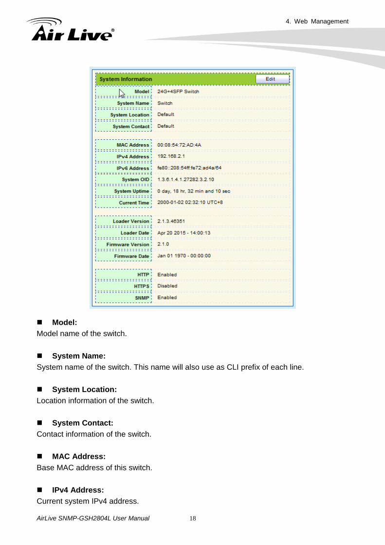
4.4 Status Use the Status pages to view system information and status. Status includes the following functions: System Information Logging Message Port-Statistics , Bandwidth Utilization Link Aggregation MAC Address Table In the following sessions, we will talk in detail about the management functions under the Configuration menu. 4.4.1. System Information System configuration is one of the most important functions. Without a proper setting, network administrator would not be able to manage the device. The switch supports manual IP address setting.
4. Web Management
AirLive SNMP-GSH2804L User Manual 18
Model: Model name of the switch. System Name: System name of the switch. This name will also use as CLI prefix of each line. System Location: Location information of the switch. System Contact: Contact information of the switch. MAC Address: Base MAC address of this switch. IPv4 Address: Current system IPv4 address.
4. Web Management
AirLive SNMP-GSH2804L User Manual 19
IPv6 Address: Current system IPv6 address. System OID: SNMP system object ID. System Uptime: Total elapsed time from booting. Current Time: Current system time. Loader Version: Boot loader image version. Loader Date: Boot loader image build date. Firmware Version: Current running firmware image version. Firmware Date: Current running firmware image build date. Telnet: Current Telnet service enable/disable state. HTTP: Current HTTP service enable/disable state. HTTPS: Current HTTP service enable/disable state SNMP: Current SNMP service enable/disable state. Click “Edit” button on the table title to edit following system information. System Name: System name of the switch. This name will also use as CLI prefix of each line.
4. Web Management
AirLive SNMP-GSH2804L User Manual 20
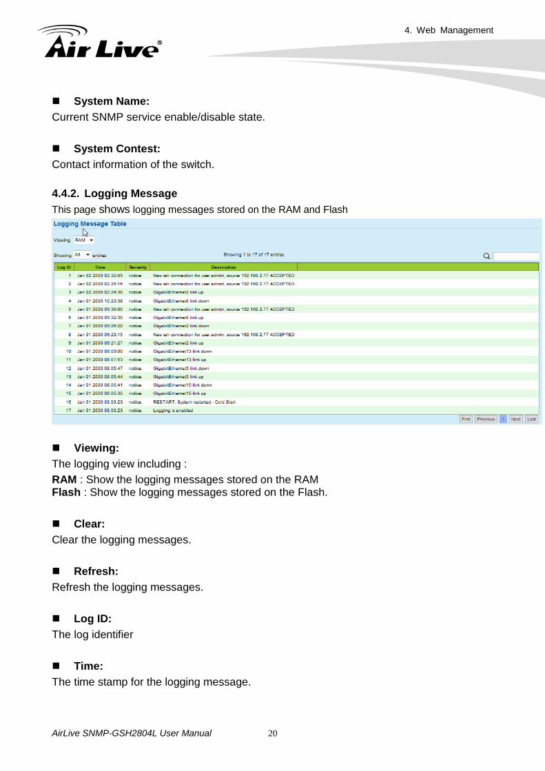
System Name: Current SNMP service enable/disable state. System Contest: Contact information of the switch. 4.4.2. Logging Message This page shows logging messages stored on the RAM and Flash
Viewing: The logging view including : RAM : Show the logging messages stored on the RAM Flash : Show the logging messages stored on the Flash. Clear: Clear the logging messages. Refresh: Refresh the logging messages. Log ID: The log identifier Time: The time stamp for the logging message.
4. Web Management
AirLive SNMP-GSH2804L User Manual 21
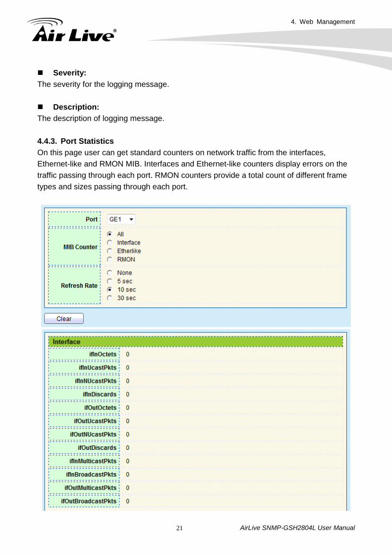
Severity: The severity for the logging message. Description: The description of logging message. 4.4.3. Port Statistics On this page user can get standard counters on network traffic from the interfaces, Ethernet-like and RMON MIB. Interfaces and Ethernet-like counters display errors on the traffic passing through each port. RMON counters provide a total count of different frame types and sizes passing through each port.
4. Web Management
AirLive SNMP-GSH2804L User Manual 22
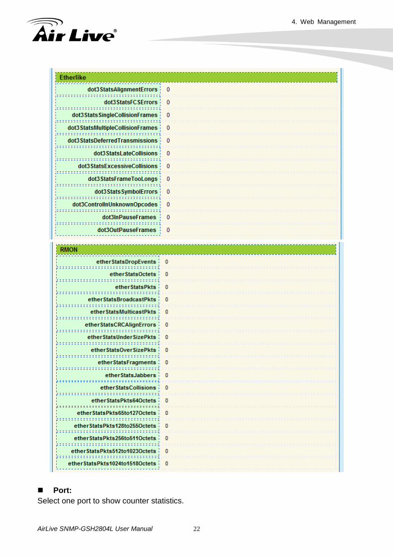
Port: Select one port to show counter statistics.
4. Web Management
AirLive SNMP-GSH2804L User Manual 23
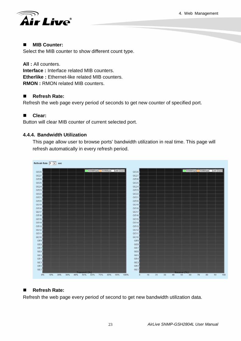
MIB Counter: Select the MIB counter to show different count type. All : All counters. Interface : Interface related MIB counters. Etherlike : Ethernet-like related MIB counters. RMON : RMON related MIB counters. Refresh Rate: Refresh the web page every period of seconds to get new counter of specified port. Clear: Button will clear MIB counter of current selected port. 4.4.4. Bandwidth Utilization
This page allow user to browse ports’ bandwidth utilization in real time. This page will refresh automatically in every refresh period.
Refresh Rate: Refresh the web page every period of second to get new bandwidth utilization data.
4. Web Management
AirLive SNMP-GSH2804L User Manual 24
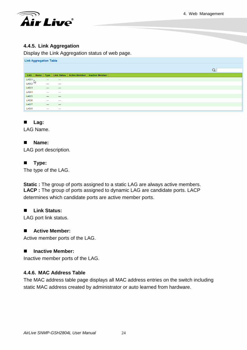
4.4.5. Link Aggregation Display the Link Aggregation status of web page.
Lag: LAG Name.
Name: LAG port description.
Type: The type of the LAG. Static : The group of ports assigned to a static LAG are always active members. LACP : The group of ports assigned to dynamic LAG are candidate ports. LACP determines which candidate ports are active member ports.
Link Status: LAG port link status.
Active Member: Active member ports of the LAG.
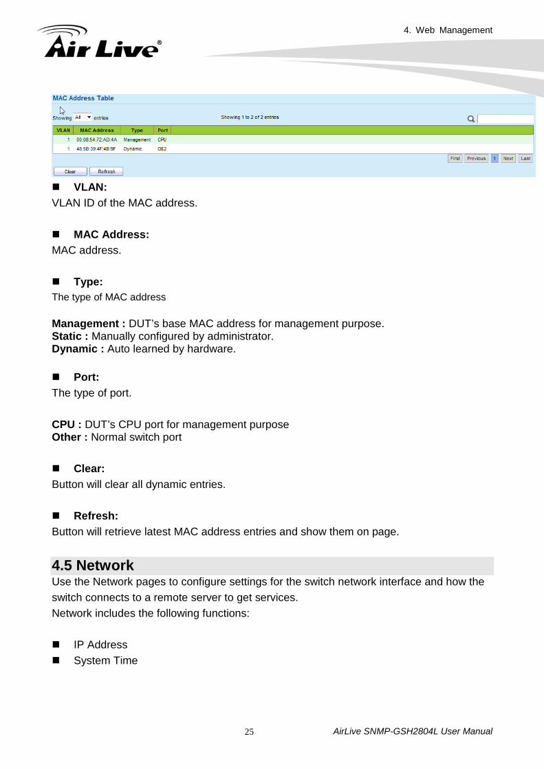
Inactive Member: Inactive member ports of the LAG. 4.4.6. MAC Address Table The MAC address table page displays all MAC address entries on the switch including static MAC address created by administrator or auto learned from hardware.
4. Web Management
AirLive SNMP-GSH2804L User Manual 25
VLAN: VLAN ID of the MAC address. MAC Address: MAC address. Type: The type of MAC address
Management : DUT’s base MAC address for management purpose. Static : Manually configured by administrator. Dynamic : Auto learned by hardware. Port: The type of port. CPU : DUT’s CPU port for management purpose Other : Normal switch port Clear: Button will clear all dynamic entries. Refresh: Button will retrieve latest MAC address entries and show them on page.
4.5 Network Use the Network pages to configure settings for the switch network interface and how the switch connects to a remote server to get services. Network includes the following functions: IP Address System Time
4. Web Management
AirLive SNMP-GSH2804L User Manual 26
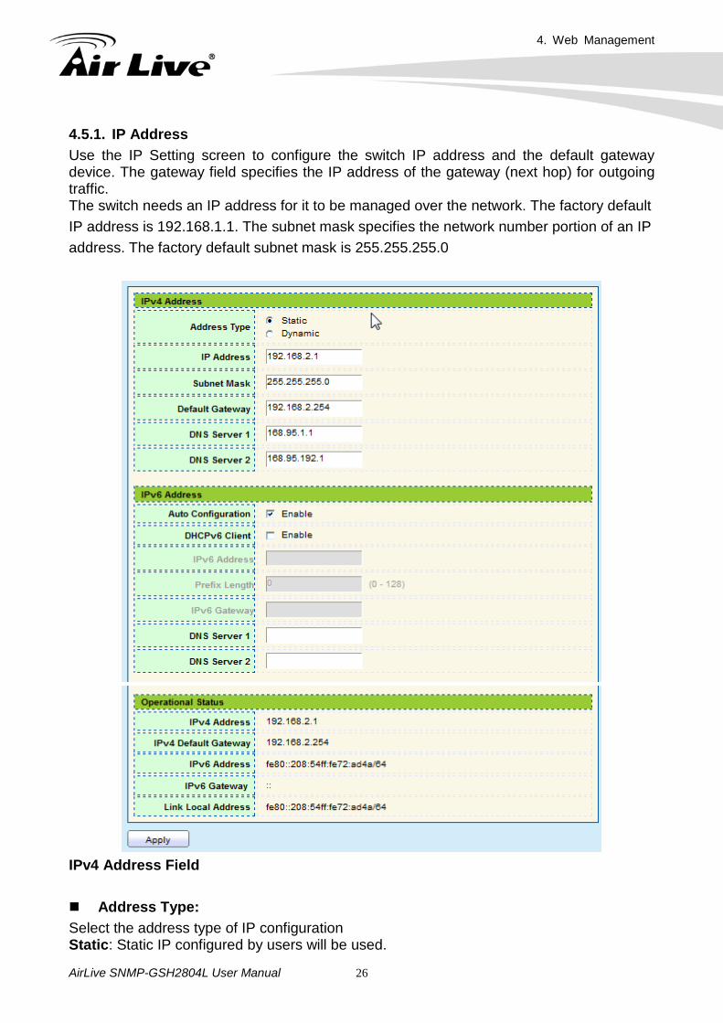
4.5.1. IP Address Use the IP Setting screen to configure the switch IP address and the default gateway device. The gateway field specifies the IP address of the gateway (next hop) for outgoing traffic. The switch needs an IP address for it to be managed over the network. The factory default IP address is 192.168.1.1. The subnet mask specifies the network number portion of an IP address. The factory default subnet mask is 255.255.255.0
IPv4 Address Field Address Type: Select the address type of IP configuration Static: Static IP configured by users will be used.
4. Web Management
AirLive SNMP-GSH2804L User Manual 27
Dynamic: Enable DHCP to obtain IP information from a DHCP server on the network. IP Address: Enter the IP address of your switch in dotted decimal notation for example 192.168.1.1. If static mode is enabled, enter IP address in this field. Subnet Mask: Enter the IP subnet mask of your switch in dotted decimal notation for example 255.255.255.0. If static mode is enabled, enter subnet mask in this field. Default Gateway: Specify the default gateway on the static configuration. The default gateway must be in the same subnet with switch IP address configuration. DNS Server 1: If static mode is enabled, enter primary DNS server address in this field. DNS Server 2: If static mode is enabled, enter secondary DNS server address in this field. IPv6 Address Field Auto Configurayion: Select Enable or Disable the IPv6 auto configuration. DHCPv6 Client: DHCPv6 client state. Enable: Enable DHCPv6 client function. Disable: Disable DHCPv6 client function. IPv6 Address: Specify the IPv6 address, when the IPv6 auto configuration and DHCPv6 client are disabled. IPv6 Prefix: Specify the prefix for the IPv6 address, when the IPv6 auto configuration and DHCPv6 client are disabled.
4. Web Management
AirLive SNMP-GSH2804L User Manual 28
DNS Server 1: Specify the primary user-defined IPv6 DNS server configuration. DNS Server 2:
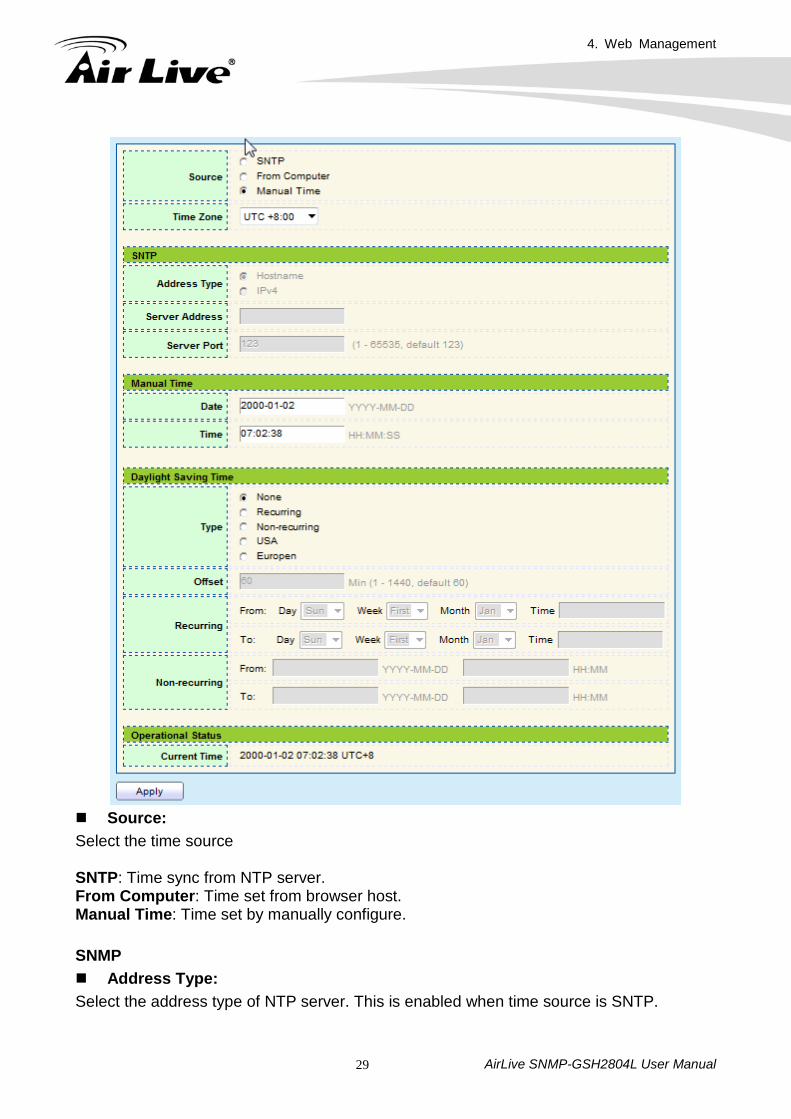
Specify the secondary user-defined IPv6 DNS server configuration. Operational Status IPv4 Address: The operational IPv4 address of the switch. IPv4 Gateway: The operational IPv4 gateway of the switch. IPv6 Address: The operational IPv6 address of the switch. IPv6 Gateway: The operational IPv6 gateway of the switch. Link Local Address: The operational IPv6 link local address for the switch. 4.5.2. System Time This page allow user to set time source, static time, time zone and daylight saving settings. Time zone and daylight saving takes effect both static time or time from SNTP server.
4. Web Management
AirLive SNMP-GSH2804L User Manual 29
Source: Select the time source SNTP: Time sync from NTP server. From Computer: Time set from browser host. Manual Time: Time set by manually configure. SNMP Address Type: Select the address type of NTP server. This is enabled when time source is SNTP.
4. Web Management
AirLive SNMP-GSH2804L User Manual 30
Server Address: Input IPv4 address or hostname for NTP server. This is enabled when time source is SNTP. Server Port: Input NTP port for NTP server. Default is 123. This is enabled when time source is SNTP. Manual Time Date: Input manual date. This is enabled when time source is manual. Time: Input manual time. This is enabled when time source is manual. Daylight Saving Time Type: Select the mode of daylight saving time. Disable : Disable daylight saving time. Recurring : Using recurring mode of daylight saving time. Non-Recurring : Using non-recurring mode of daylight saving time. USA : Using daylight saving time in the United States that starts on the second Sunday of March and ends on the first Sunday of November European : Using daylight saving time in the Europe that starts on the last Sunday in March and ending on the last Sunday in October. Offset: Specify the adjust offset of daylight saving time. Recurring From: Specify the starting time of recurring daylight saving time. This field available when selecting “Recurring” mode. Recurring To: Specify the ending time of recurring daylight saving time. This field available when selecting “Recurring” mode. Non-recurring From: Specify the starting time of non-recurring daylight saving time. This field available when selecting “Non-Recurring” mode.
4. Web Management
AirLive SNMP-GSH2804L User Manual 31
Non-recurring To: Specify the ending time of non-recurring daylight saving time. This field available when selecting “Non-Recurring” mode.
4.6 Port Use the Port pages to configure settings for the switch port related features. Port includes the following functions: Port Setting Link Aggregation Group Link Aggregation Port Setting Link Aggregation LACP
EEE
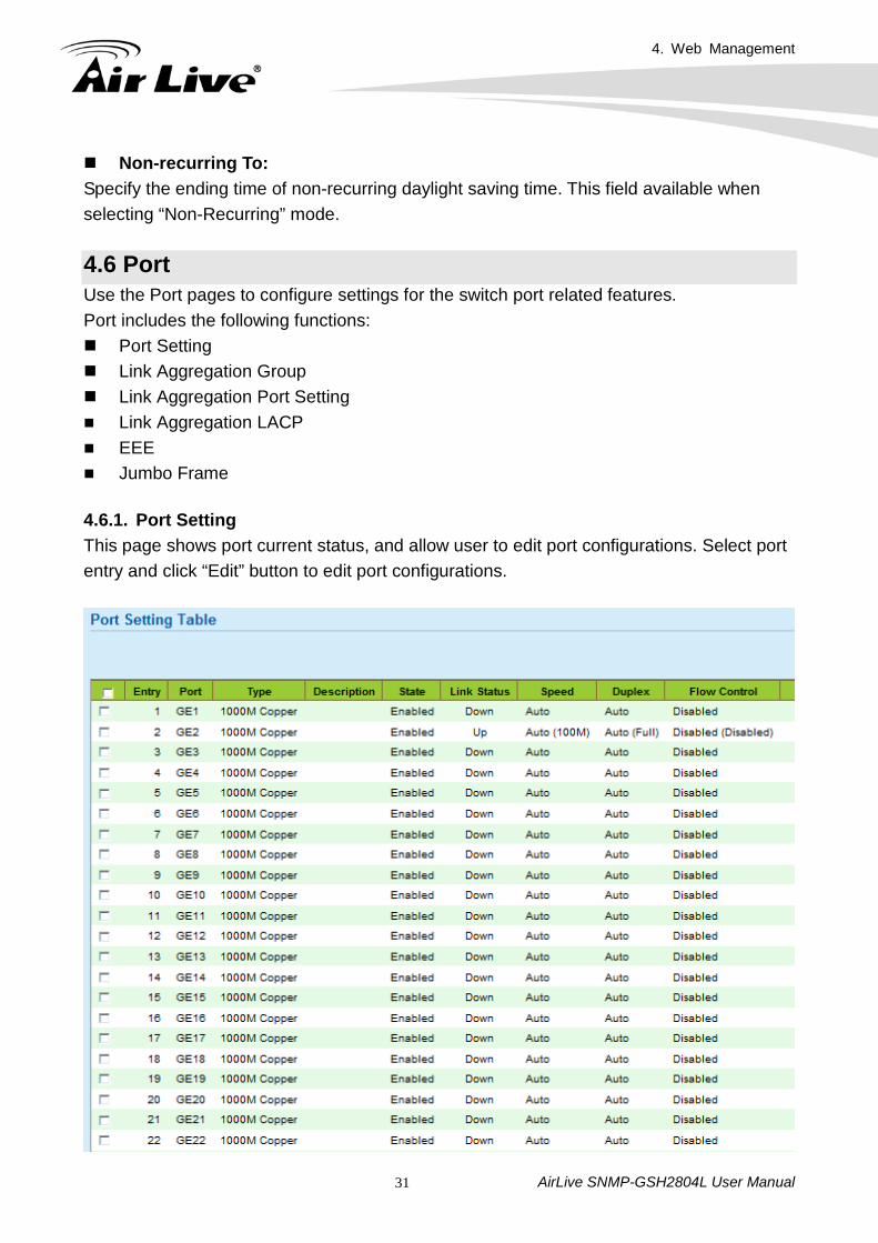
Jumbo Frame 4.6.1. Port Setting This page shows port current status, and allow user to edit port configurations. Select port entry and click “Edit” button to edit port configurations.
4. Web Management
AirLive SNMP-GSH2804L User Manual 32
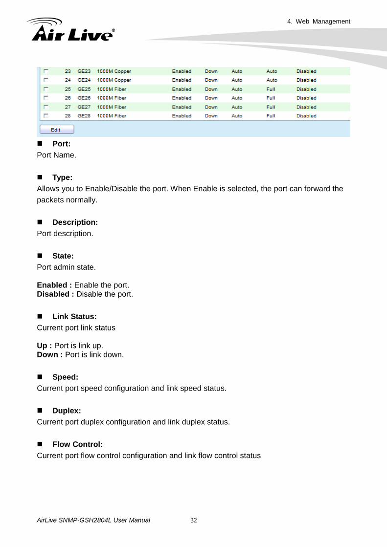
Port: Port Name. Type: Allows you to Enable/Disable the port. When Enable is selected, the port can forward the packets normally. Description: Port description. State: Port admin state. Enabled : Enable the port. Disabled : Disable the port. Link Status: Current port link status Up : Port is link up. Down : Port is link down. Speed: Current port speed configuration and link speed status. Duplex: Current port duplex configuration and link duplex status. Flow Control: Current port flow control configuration and link flow control status
4. Web Management
AirLive SNMP-GSH2804L User Manual 33
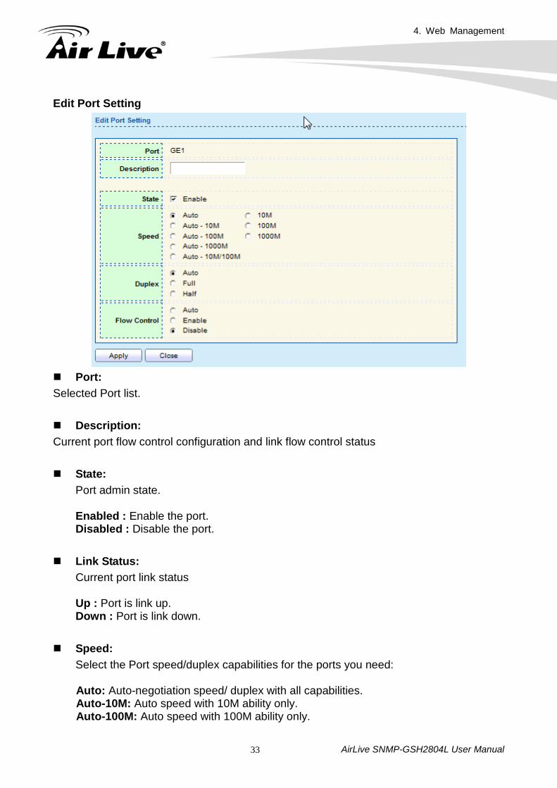
Edit Port Setting
Port: Selected Port list. Description: Current port flow control configuration and link flow control status State:
Port admin state. Enabled : Enable the port. Disabled : Disable the port.
Link Status:
Current port link status Up : Port is link up. Down : Port is link down.
Speed:
Select the Port speed/duplex capabilities for the ports you need: Auto: Auto-negotiation speed/ duplex with all capabilities. Auto-10M: Auto speed with 10M ability only. Auto-100M: Auto speed with 100M ability only.
4. Web Management
AirLive SNMP-GSH2804L User Manual 34
Auto-1000M: Auto speed with 1000M ability only. Auto-10M/100M: Auto speed with 10M/100M abilities. 10M: Force speed with 10M ability. 100M: Force speed with 100M ability. 1000M: Force speed with 1000M ability
Duplex: Port duplex capabilities Auto: Auto flow control ability. Enabled: Enable flow control ability. Disabled: Disable flow control ability.
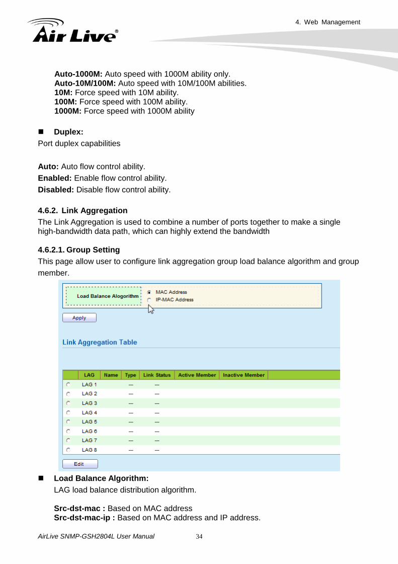
4.6.2. Link Aggregation The Link Aggregation is used to combine a number of ports together to make a single high-bandwidth data path, which can highly extend the bandwidth 4.6.2.1. Group Setting This page allow user to configure link aggregation group load balance algorithm and group member.
Load Balance Algorithm:
LAG load balance distribution algorithm. Src-dst-mac : Based on MAC address Src-dst-mac-ip : Based on MAC address and IP address.
4. Web Management
AirLive SNMP-GSH2804L User Manual 35
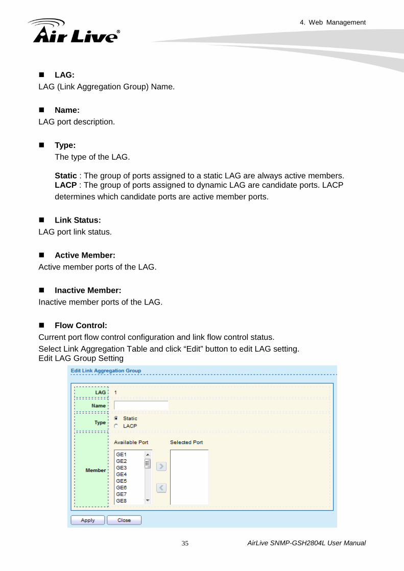
LAG: LAG (Link Aggregation Group) Name. Name: LAG port description. Type:
The type of the LAG. Static : The group of ports assigned to a static LAG are always active members. LACP : The group of ports assigned to dynamic LAG are candidate ports. LACP determines which candidate ports are active member ports.
Link Status: LAG port link status. Active Member: Active member ports of the LAG. Inactive Member: Inactive member ports of the LAG. Flow Control: Current port flow control configuration and link flow control status. Select Link Aggregation Table and click “Edit” button to edit LAG setting. Edit LAG Group Setting
4. Web Management
AirLive SNMP-GSH2804L User Manual 36
LAG: Selected LAG Group ID. Name: LAG port description. Type:
The type of the LAG. Static : The group of ports assigned to a static LAG are always active members. LACP : The group of ports assigned to dynamic LAG are candidate ports. LACP determines which candidate ports are active member ports.
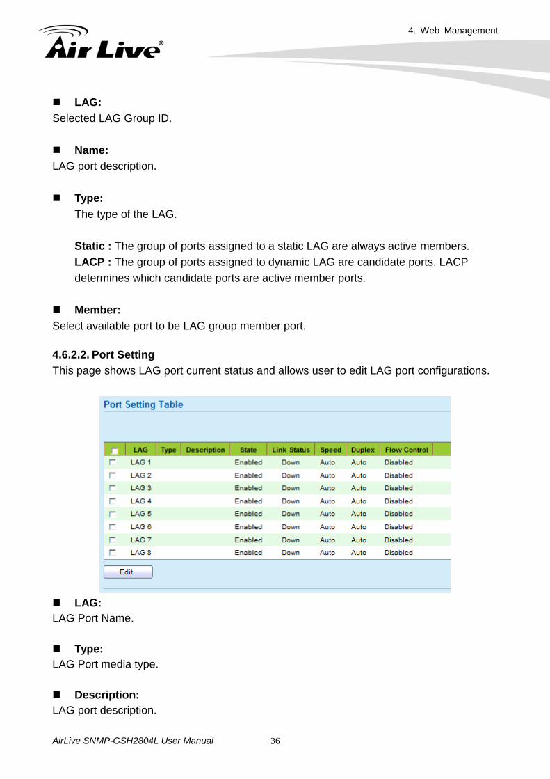
Member: Select available port to be LAG group member port. 4.6.2.2. Port Setting This page shows LAG port current status and allows user to edit LAG port configurations.
LAG: LAG Port Name. Type: LAG Port media type. Description: LAG port description.
4. Web Management
AirLive SNMP-GSH2804L User Manual 37
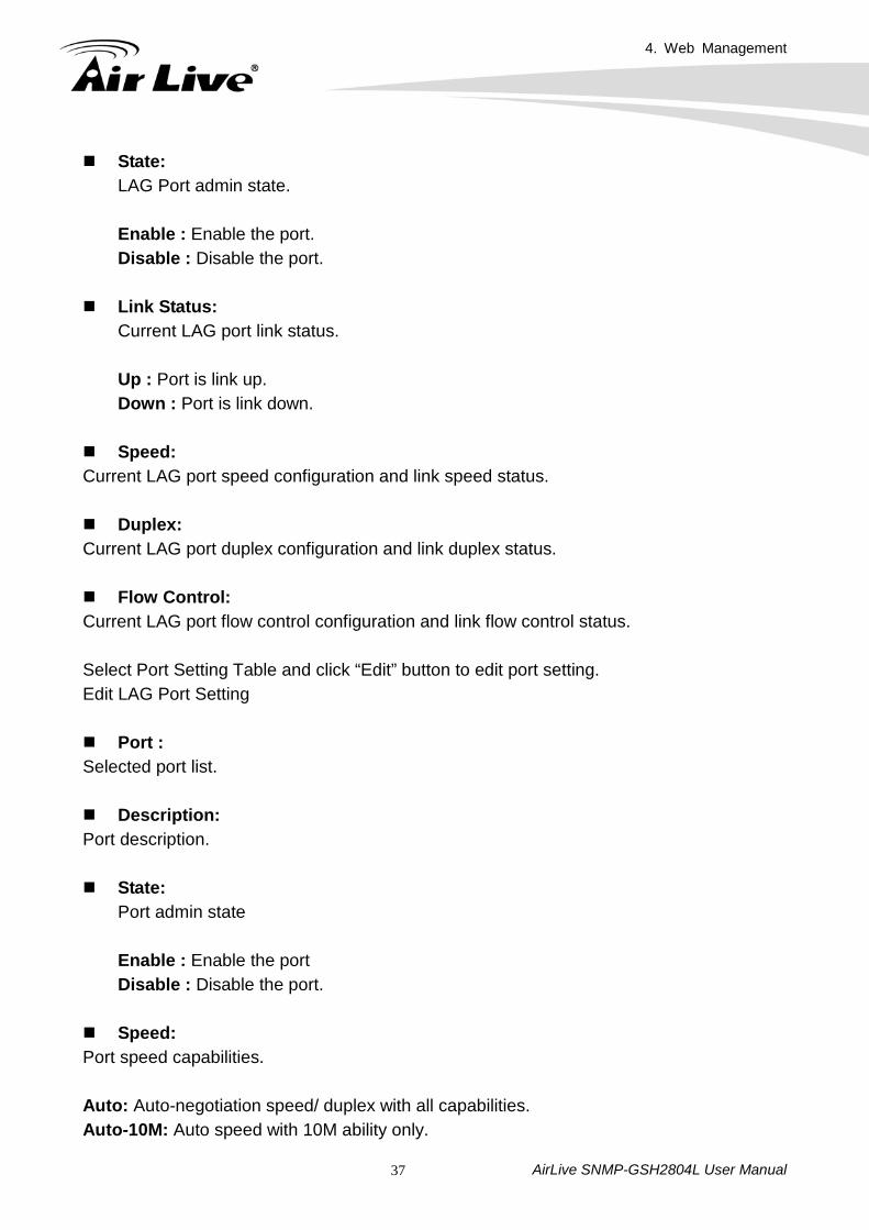
State: LAG Port admin state. Enable : Enable the port. Disable : Disable the port.
Link Status:
Current LAG port link status. Up : Port is link up. Down : Port is link down.
Speed: Current LAG port speed configuration and link speed status. Duplex: Current LAG port duplex configuration and link duplex status. Flow Control: Current LAG port flow control configuration and link flow control status. Select Port Setting Table and click “Edit” button to edit port setting. Edit LAG Port Setting Port : Selected port list. Description: Port description. State:
Port admin state Enable : Enable the port Disable : Disable the port.
Speed: Port speed capabilities. Auto: Auto-negotiation speed/ duplex with all capabilities. Auto-10M: Auto speed with 10M ability only.
4. Web Management
AirLive SNMP-GSH2804L User Manual 38
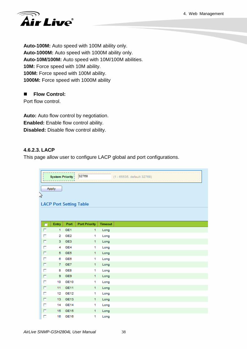
Auto-100M: Auto speed with 100M ability only. Auto-1000M: Auto speed with 1000M ability only. Auto-10M/100M: Auto speed with 10M/100M abilities. 10M: Force speed with 10M ability. 100M: Force speed with 100M ability. 1000M: Force speed with 1000M ability Flow Control: Port flow control. Auto: Auto flow control by negotiation. Enabled: Enable flow control ability. Disabled: Disable flow control ability. 4.6.2.3. LACP This page allow user to configure LACP global and port configurations.
4. Web Management
AirLive SNMP-GSH2804L User Manual 39
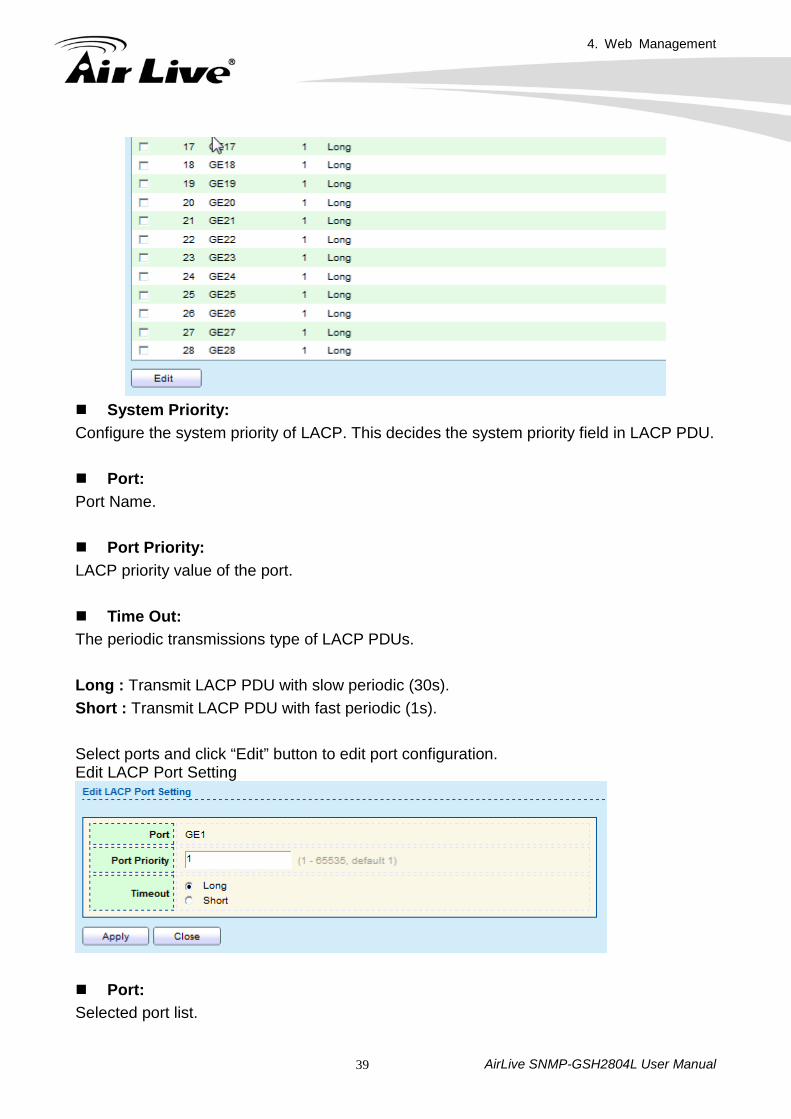
System Priority: Configure the system priority of LACP. This decides the system priority field in LACP PDU. Port: Port Name. Port Priority: LACP priority value of the port. Time Out: The periodic transmissions type of LACP PDUs. Long : Transmit LACP PDU with slow periodic (30s). Short : Transmit LACP PDU with fast periodic (1s). Select ports and click “Edit” button to edit port configuration. Edit LACP Port Setting
Port: Selected port list.
4. Web Management
AirLive SNMP-GSH2804L User Manual 40
Port Priority: Enter the LACP priority value of the port.
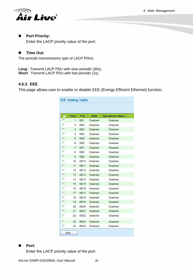
Time Out: The periodic transmissions type of LACP PDUs. Long : Transmit LACP PDU with slow periodic (30s). Short : Transmit LACP PDU with fast periodic (1s). 4.6.3. EEE This page allows user to enable or disable EEE (Energy Efficient Ethernet) function.
Port: Enter the LACP priority value of the port.
4. Web Management
AirLive SNMP-GSH2804L User Manual 41
State: Port EEE admin state. Enable : EEE is enabled Disable : EEE is disabled. Operational Status: Port EEE operational status. Enable : EEE is operating Disable : EEE is no operating
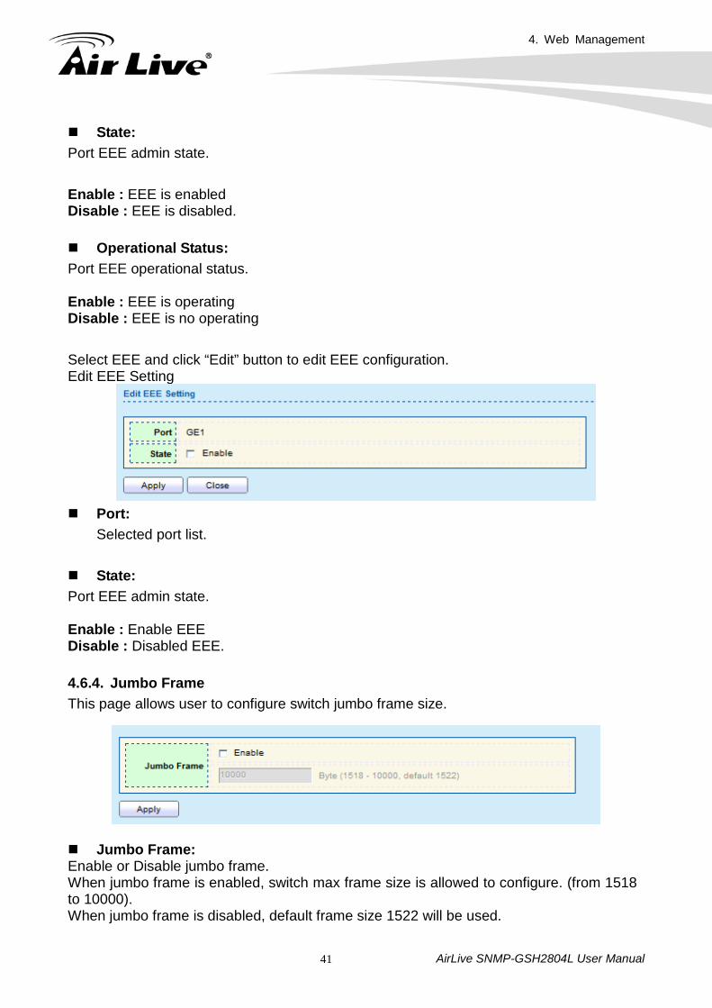
Select EEE and click “Edit” button to edit EEE configuration. Edit EEE Setting
Port:
Selected port list. State: Port EEE admin state. Enable : Enable EEE Disable : Disabled EEE.
4.6.4. Jumbo Frame This page allows user to configure switch jumbo frame size.
Jumbo Frame: Enable or Disable jumbo frame. When jumbo frame is enabled, switch max frame size is allowed to configure. (from 1518 to 10000). When jumbo frame is disabled, default frame size 1522 will be used.
4. Web Management
AirLive SNMP-GSH2804L User Manual 42
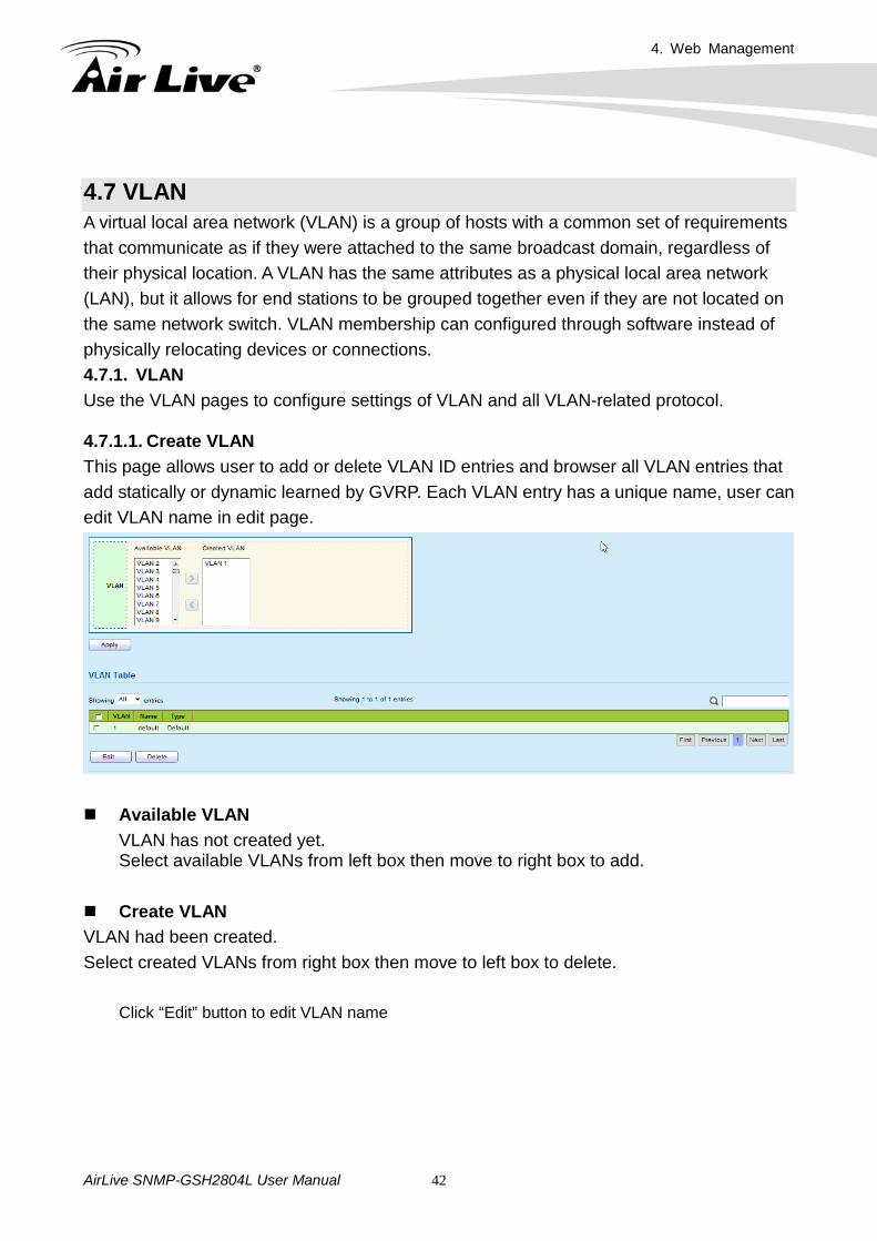
4.7 VLAN A virtual local area network (VLAN) is a group of hosts with a common set of requirements that communicate as if they were attached to the same broadcast domain, regardless of their physical location. A VLAN has the same attributes as a physical local area network (LAN), but it allows for end stations to be grouped together even if they are not located on the same network switch. VLAN membership can configured through software instead of physically relocating devices or connections. 4.7.1. VLAN Use the VLAN pages to configure settings of VLAN and all VLAN-related protocol. 4.7.1.1. Create VLAN This page allows user to add or delete VLAN ID entries and browser all VLAN entries that add statically or dynamic learned by GVRP. Each VLAN entry has a unique name, user can edit VLAN name in edit page.
Available VLAN VLAN has not created yet. Select available VLANs from left box then move to right box to add.
Create VLAN VLAN had been created. Select created VLANs from right box then move to left box to delete.
Click “Edit” button to edit VLAN name
4. Web Management
AirLive SNMP-GSH2804L User Manual 43
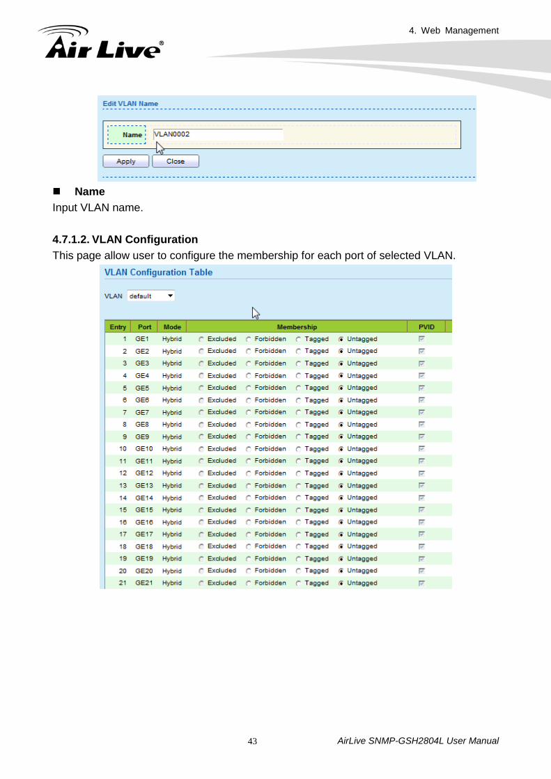
Name Input VLAN name. 4.7.1.2. VLAN Configuration This page allow user to configure the membership for each port of selected VLAN.
4. Web Management
AirLive SNMP-GSH2804L User Manual 44
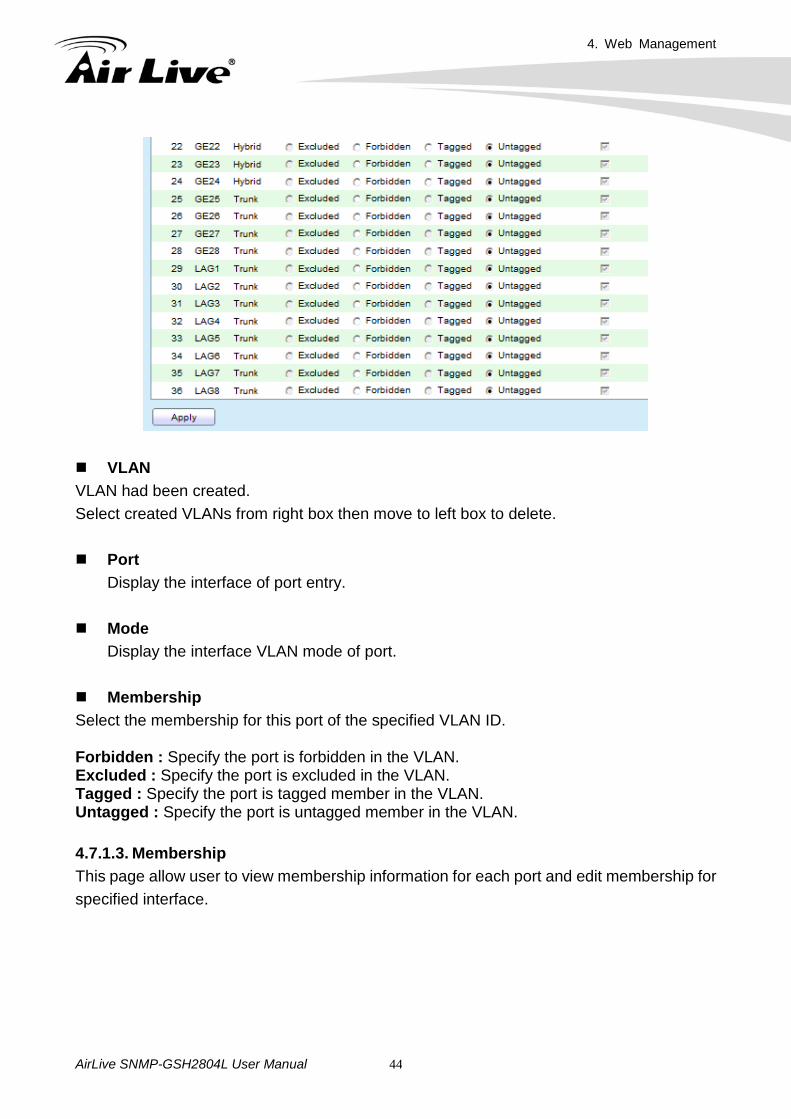
VLAN VLAN had been created. Select created VLANs from right box then move to left box to delete. Port
Display the interface of port entry. Mode
Display the interface VLAN mode of port. Membership Select the membership for this port of the specified VLAN ID. Forbidden : Specify the port is forbidden in the VLAN. Excluded : Specify the port is excluded in the VLAN. Tagged : Specify the port is tagged member in the VLAN. Untagged : Specify the port is untagged member in the VLAN. 4.7.1.3. Membership This page allow user to view membership information for each port and edit membership for specified interface.
4. Web Management
AirLive SNMP-GSH2804L User Manual 45
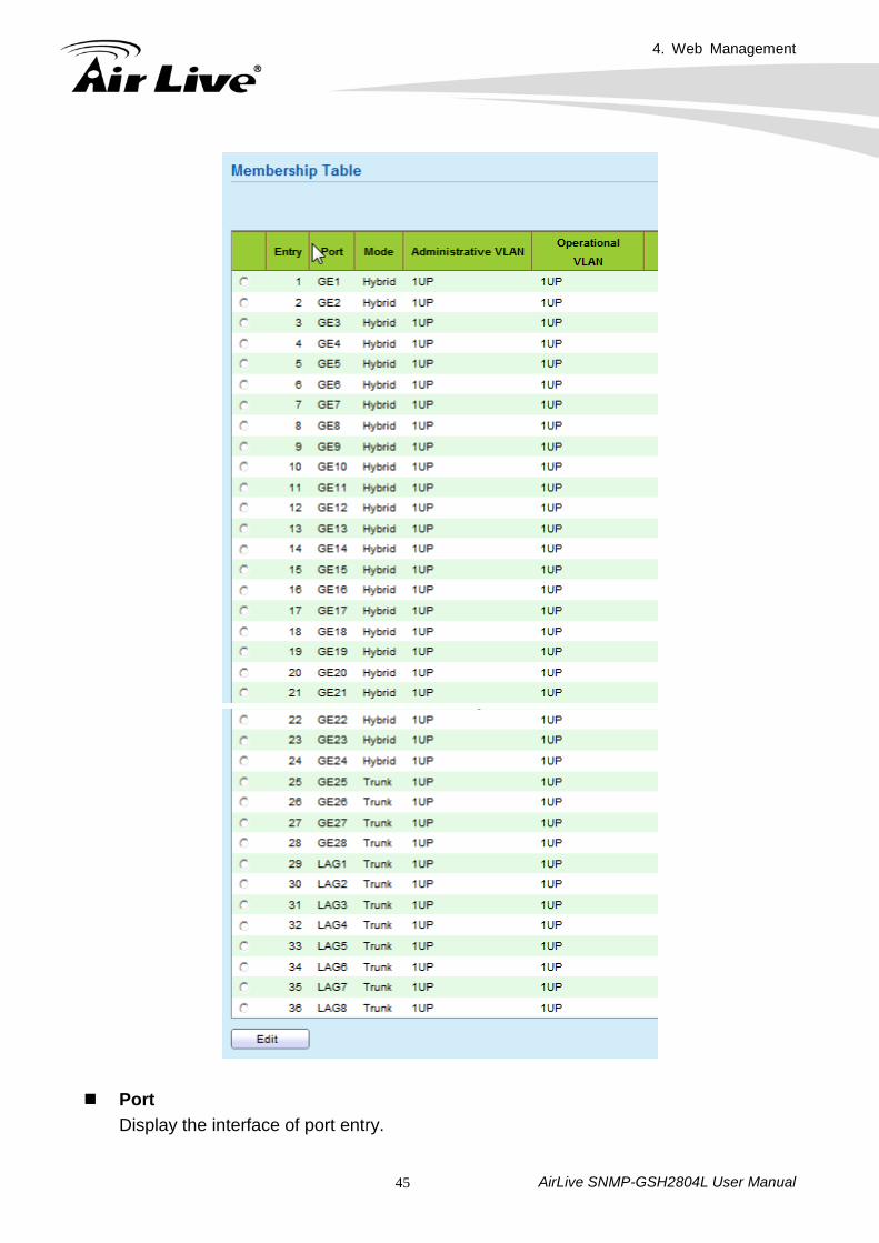
Port
Display the interface of port entry.
4. Web Management
AirLive SNMP-GSH2804L User Manual 46
Mode Display the interface VLAN mode of port.
Administrative VLAN
Display the administrative VLAN list of this port. Operational VLAN
Display the operational VLAN list of this port. Operational VLAN means the VLAN status that really runs in device. It may different to administrative VLAN.
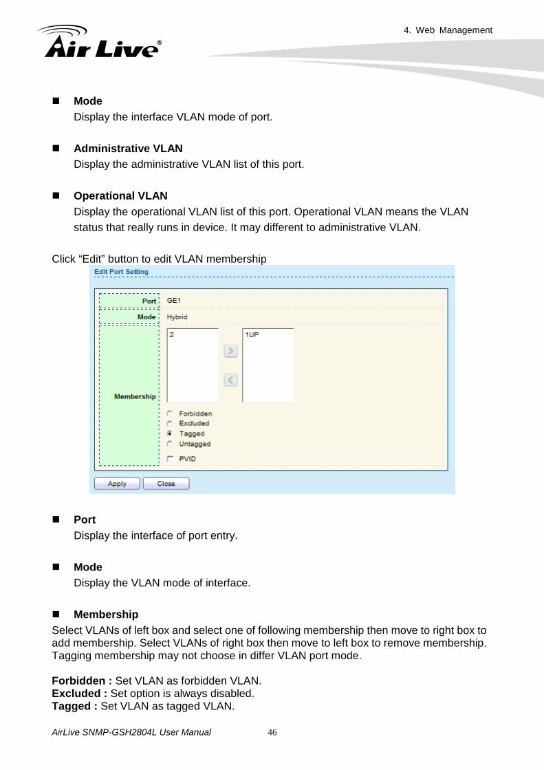
Click “Edit” button to edit VLAN membership
Port
Display the interface of port entry. Mode
Display the VLAN mode of interface. Membership Select VLANs of left box and select one of following membership then move to right box to add membership. Select VLANs of right box then move to left box to remove membership. Tagging membership may not choose in differ VLAN port mode. Forbidden : Set VLAN as forbidden VLAN. Excluded : Set option is always disabled. Tagged : Set VLAN as tagged VLAN.
4. Web Management
AirLive SNMP-GSH2804L User Manual 47
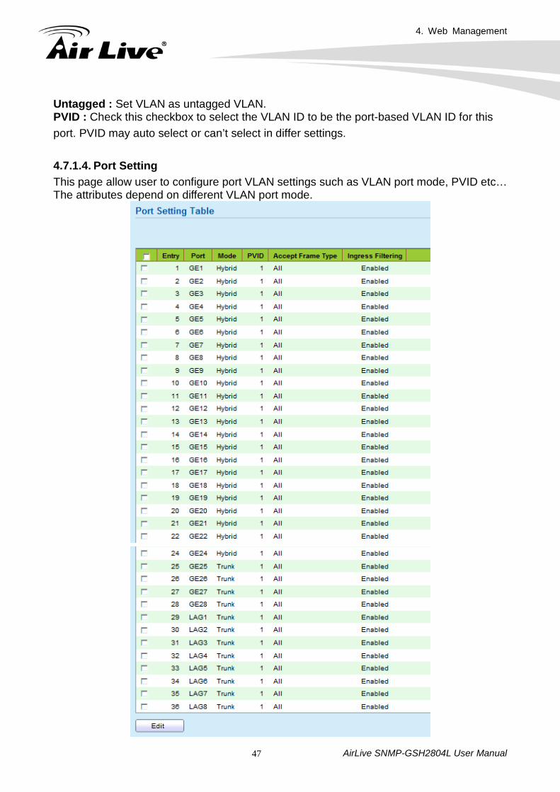
Untagged : Set VLAN as untagged VLAN. PVID : Check this checkbox to select the VLAN ID to be the port-based VLAN ID for this port. PVID may auto select or can’t select in differ settings. 4.7.1.4. Port Setting This page allow user to configure port VLAN settings such as VLAN port mode, PVID etc… The attributes depend on different VLAN port mode.
4. Web Management
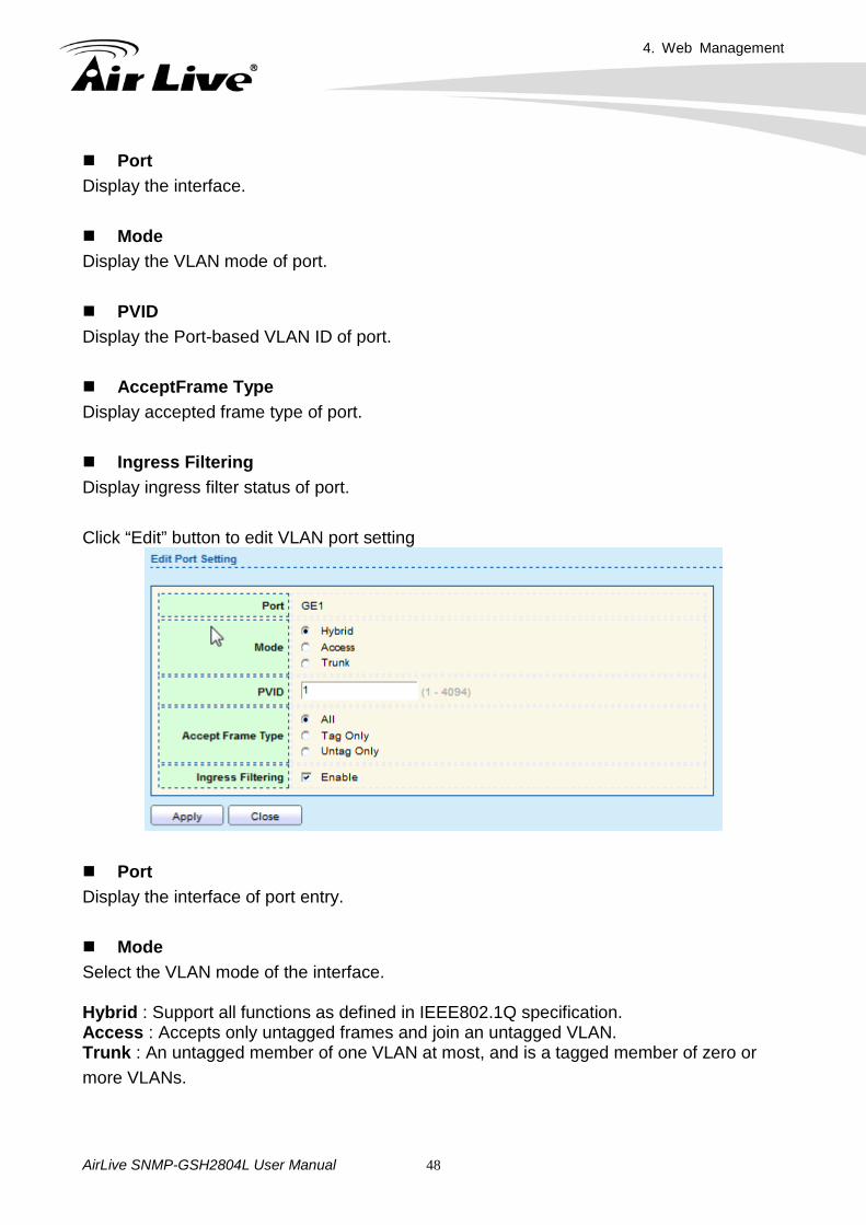
AirLive SNMP-GSH2804L User Manual 48
Port Display the interface. Mode Display the VLAN mode of port. PVID Display the Port-based VLAN ID of port. AcceptFrame Type Display accepted frame type of port. Ingress Filtering Display ingress filter status of port. Click “Edit” button to edit VLAN port setting
Port Display the interface of port entry. Mode Select the VLAN mode of the interface. Hybrid : Support all functions as defined in IEEE802.1Q specification. Access : Accepts only untagged frames and join an untagged VLAN. Trunk : An untagged member of one VLAN at most, and is a tagged member of zero or more VLANs.
4. Web Management
AirLive SNMP-GSH2804L User Manual 49
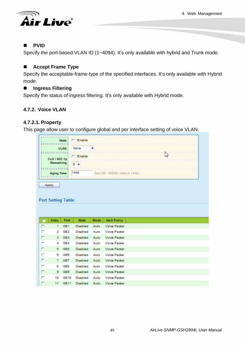
PVID Specify the port-based VLAN ID (1~4094). It’s only available with hybrid and Trunk mode. Accept Frame Type Specify the acceptable-frame-type of the specified interfaces. It’s only available with Hybrid mode. Ingress Filtering Specify the status of ingress filtering. It’s only available with Hybrid mode. 4.7.2. Voice VLAN 4.7.2.1. Property This page allow user to configure global and per interface setting of voice VLAN.
4. Web Management
AirLive SNMP-GSH2804L User Manual 50
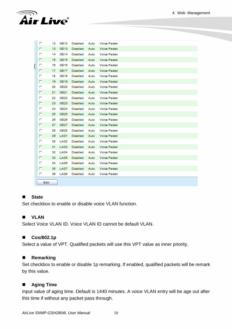
State Set checkbox to enable or disable voice VLAN function. VLAN Select Voice VLAN ID. Voice VLAN ID cannot be default VLAN. Cos/802.1p Select a value of VPT. Qualified packets will use this VPT value as inner priority. Remarking Set checkbox to enable or disable 1p remarking. If enabled, qualified packets will be remark by this value. Aging Time Input value of aging time. Default is 1440 minutes. A voice VLAN entry will be age out after this time if without any packet pass through.
4. Web Management
AirLive SNMP-GSH2804L User Manual 51
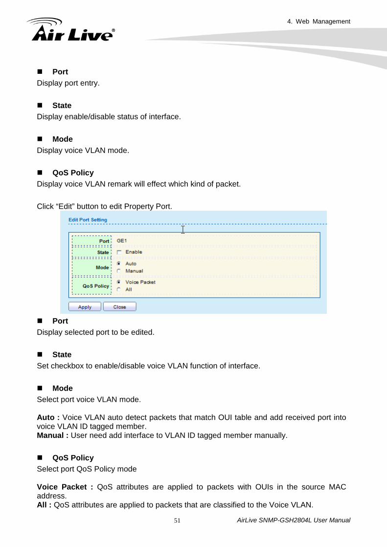
Port Display port entry. State Display enable/disable status of interface. Mode Display voice VLAN mode. QoS Policy Display voice VLAN remark will effect which kind of packet. Click “Edit” button to edit Property Port.
Port Display selected port to be edited. State Set checkbox to enable/disable voice VLAN function of interface. Mode Select port voice VLAN mode. Auto : Voice VLAN auto detect packets that match OUI table and add received port into voice VLAN ID tagged member. Manual : User need add interface to VLAN ID tagged member manually. QoS Policy Select port QoS Policy mode Voice Packet : QoS attributes are applied to packets with OUIs in the source MAC address. All : QoS attributes are applied to packets that are classified to the Voice VLAN.
4. Web Management
AirLive SNMP-GSH2804L User Manual 52
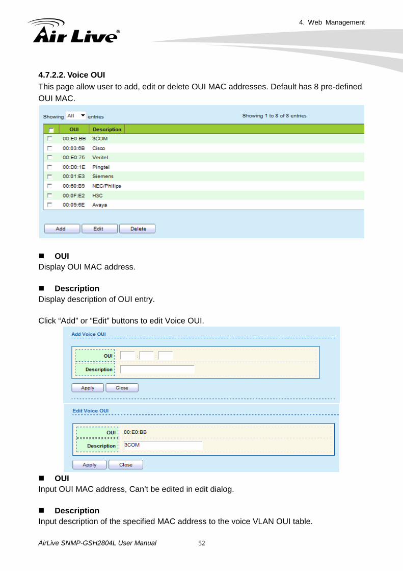
4.7.2.2. Voice OUI This page allow user to add, edit or delete OUI MAC addresses. Default has 8 pre-defined OUI MAC.
OUI Display OUI MAC address. Description Display description of OUI entry. Click “Add” or “Edit” buttons to edit Voice OUI.
OUI Input OUI MAC address, Can’t be edited in edit dialog. Description Input description of the specified MAC address to the voice VLAN OUI table.
4. Web Management
AirLive SNMP-GSH2804L User Manual 53
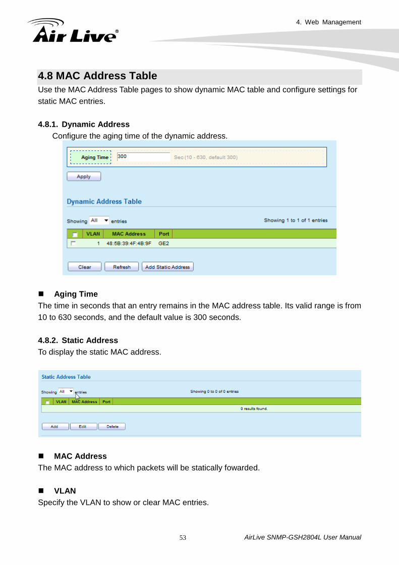
4.8 MAC Address Table Use the MAC Address Table pages to show dynamic MAC table and configure settings for static MAC entries. 4.8.1. Dynamic Address
Configure the aging time of the dynamic address.
Aging Time The time in seconds that an entry remains in the MAC address table. Its valid range is from 10 to 630 seconds, and the default value is 300 seconds. 4.8.2. Static Address To display the static MAC address.
MAC Address The MAC address to which packets will be statically fowarded. VLAN Specify the VLAN to show or clear MAC entries.
4. Web Management
AirLive SNMP-GSH2804L User Manual 54
Port Interface or port number.
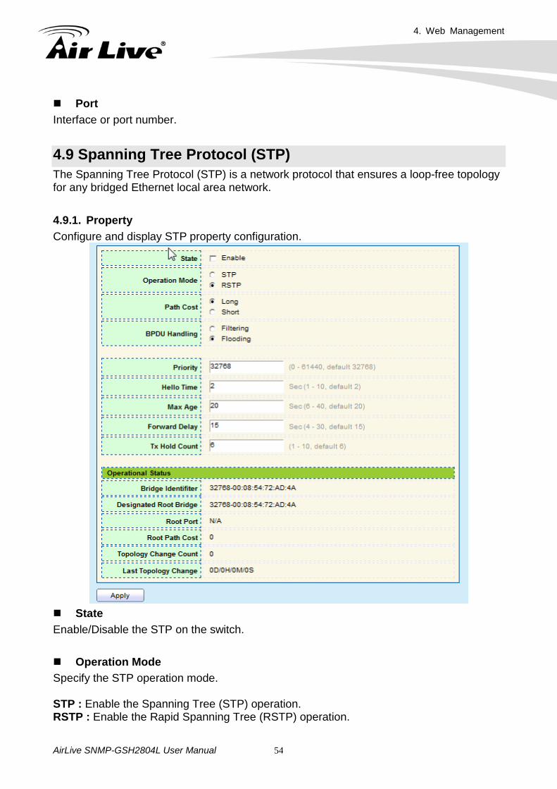
4.9 Spanning Tree Protocol (STP) The Spanning Tree Protocol (STP) is a network protocol that ensures a loop-free topology for any bridged Ethernet local area network. 4.9.1. Property Configure and display STP property configuration.
State Enable/Disable the STP on the switch. Operation Mode Specify the STP operation mode. STP : Enable the Spanning Tree (STP) operation. RSTP : Enable the Rapid Spanning Tree (RSTP) operation.
4. Web Management
AirLive SNMP-GSH2804L User Manual 55
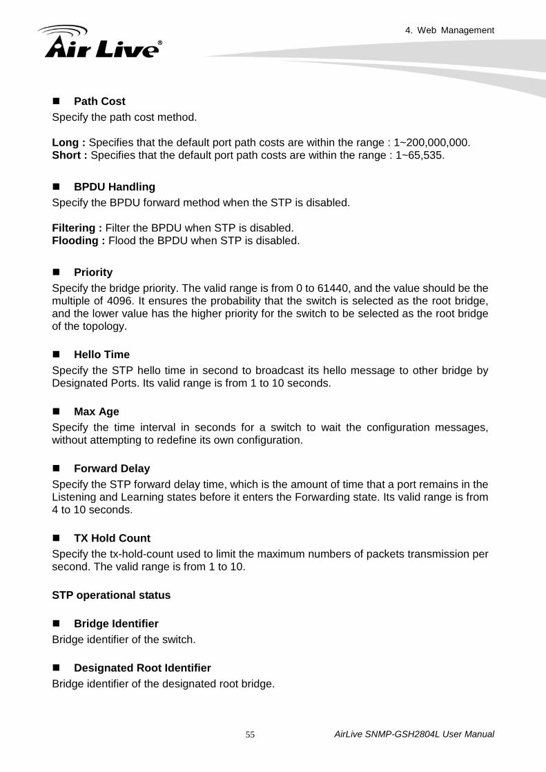
Path Cost Specify the path cost method. Long : Specifies that the default port path costs are within the range : 1~200,000,000. Short : Specifies that the default port path costs are within the range : 1~65,535. BPDU Handling Specify the BPDU forward method when the STP is disabled. Filtering : Filter the BPDU when STP is disabled. Flooding : Flood the BPDU when STP is disabled. Priority Specify the bridge priority. The valid range is from 0 to 61440, and the value should be the multiple of 4096. It ensures the probability that the switch is selected as the root bridge, and the lower value has the higher priority for the switch to be selected as the root bridge of the topology. Hello Time Specify the STP hello time in second to broadcast its hello message to other bridge by Designated Ports. Its valid range is from 1 to 10 seconds. Max Age Specify the time interval in seconds for a switch to wait the configuration messages, without attempting to redefine its own configuration. Forward Delay Specify the STP forward delay time, which is the amount of time that a port remains in the Listening and Learning states before it enters the Forwarding state. Its valid range is from 4 to 10 seconds. TX Hold Count Specify the tx-hold-count used to limit the maximum numbers of packets transmission per second. The valid range is from 1 to 10. STP operational status Bridge Identifier Bridge identifier of the switch. Designated Root Identifier Bridge identifier of the designated root bridge.
4. Web Management
AirLive SNMP-GSH2804L User Manual 56
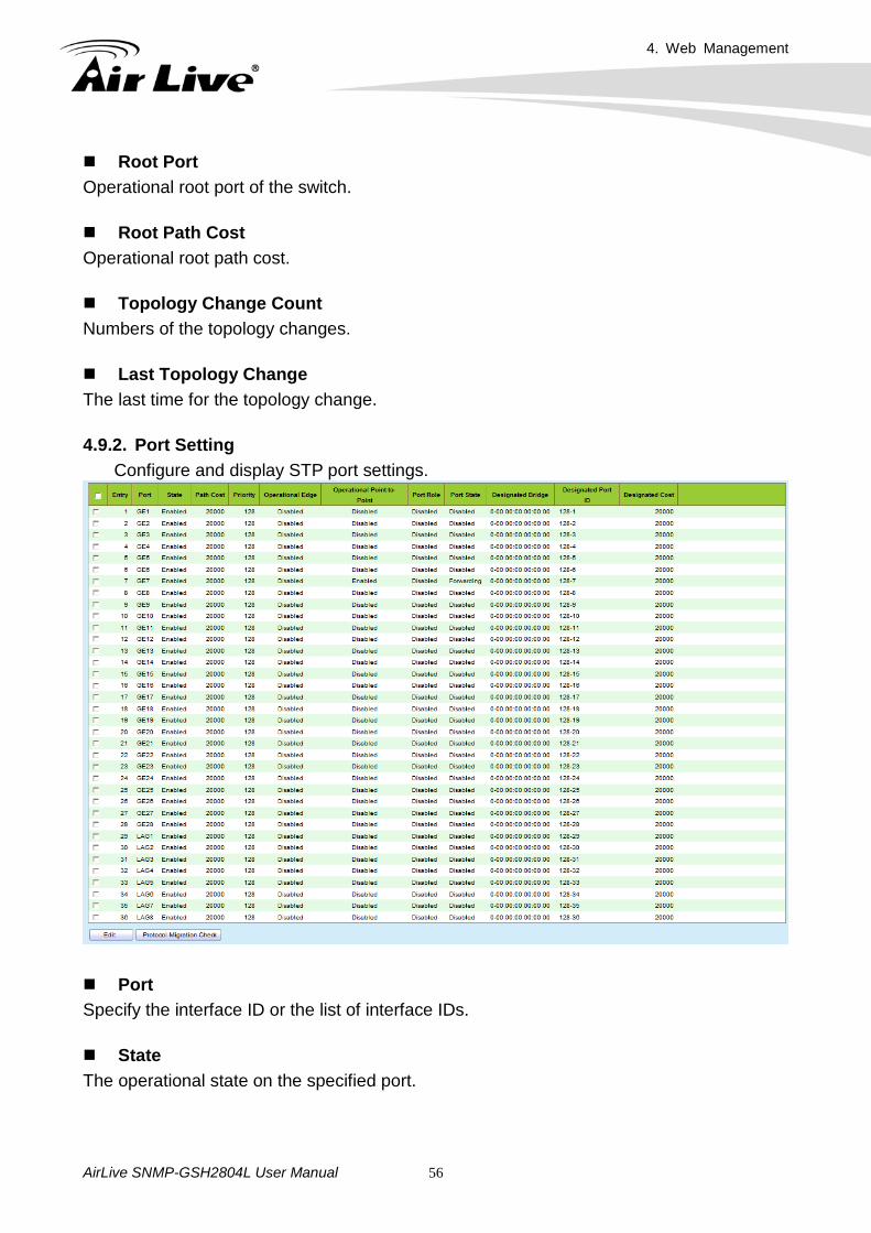
Root Port Operational root port of the switch. Root Path Cost Operational root path cost. Topology Change Count Numbers of the topology changes. Last Topology Change The last time for the topology change. 4.9.2. Port Setting
Configure and display STP port settings.
Port Specify the interface ID or the list of interface IDs. State The operational state on the specified port.
4. Web Management
AirLive SNMP-GSH2804L User Manual 57
Path Cost STP path cost on the specified port. Priority STP priority on the specified port. Operational Edge The operational state on the specified port. Operational Point-to-Point The operational edge point-to-point status on the specified port. Port Role The current port role on the specified port. The possible values are: “Disabled”, “Master”, “Root”, “Designated”, “Alternative”, and “Backup”. Port State The current port state on the specified port. The possible values are: “Disabled”, “Discarding”, “Learning”, and “Forwarding”. Designated Bridge The bridge ID of the designated bridge. Designated Port ID The designated port ID on the switch. Designated Cost The path cost of the designated port on the switch. STP port setting buttons Protocol Migration Check Restart the Spanning Tree Protocol (STP) migration process (re-negotiate with its neighborhood) on the specific interface.
4. Web Management
AirLive SNMP-GSH2804L User Manual 58
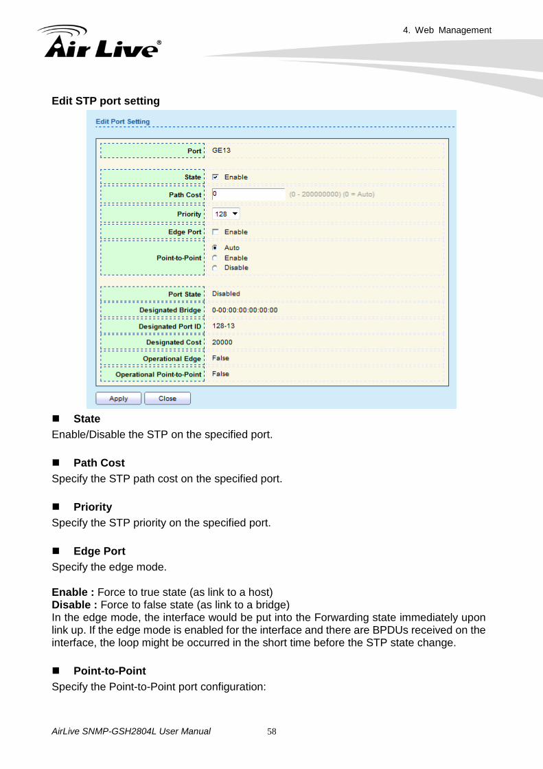
Edit STP port setting
State Enable/Disable the STP on the specified port. Path Cost Specify the STP path cost on the specified port. Priority Specify the STP priority on the specified port. Edge Port Specify the edge mode. Enable : Force to true state (as link to a host) Disable : Force to false state (as link to a bridge) In the edge mode, the interface would be put into the Forwarding state immediately upon link up. If the edge mode is enabled for the interface and there are BPDUs received on the interface, the loop might be occurred in the short time before the STP state change. Point-to-Point Specify the Point-to-Point port configuration:
4. Web Management
AirLive SNMP-GSH2804L User Manual 59
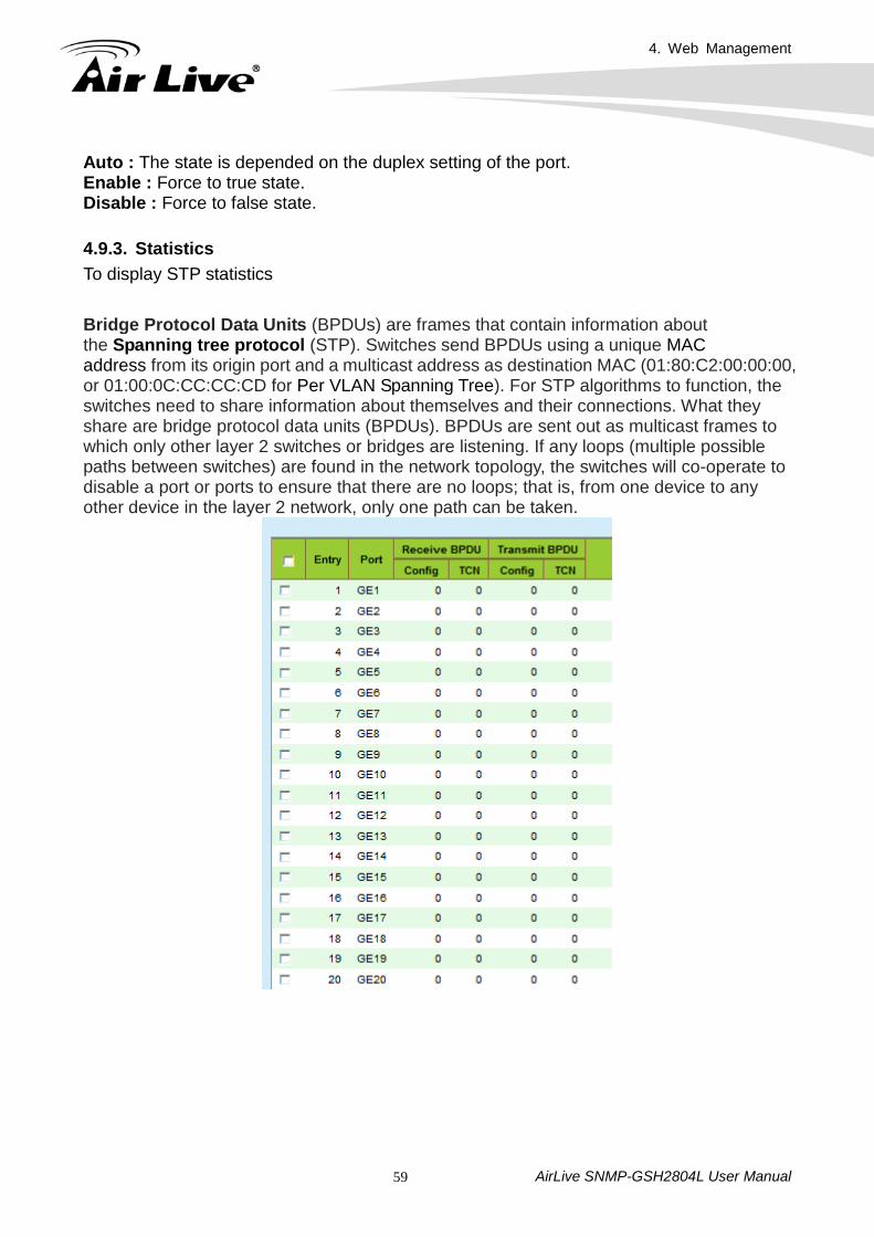
Auto : The state is depended on the duplex setting of the port. Enable : Force to true state. Disable : Force to false state. 4.9.3. Statistics To display STP statistics Bridge Protocol Data Units (BPDUs) are frames that contain information about the Spanning tree protocol (STP). Switches send BPDUs using a unique MAC address from its origin port and a multicast address as destination MAC (01:80:C2:00:00:00, or 01:00:0C:CC:CC:CD for Per VLAN Spanning Tree). For STP algorithms to function, the switches need to share information about themselves and their connections. What they share are bridge protocol data units (BPDUs). BPDUs are sent out as multicast frames to which only other layer 2 switches or bridges are listening. If any loops (multiple possible paths between switches) are found in the network topology, the switches will co-operate to disable a port or ports to ensure that there are no loops; that is, from one device to any other device in the layer 2 network, only one path can be taken.
4. Web Management
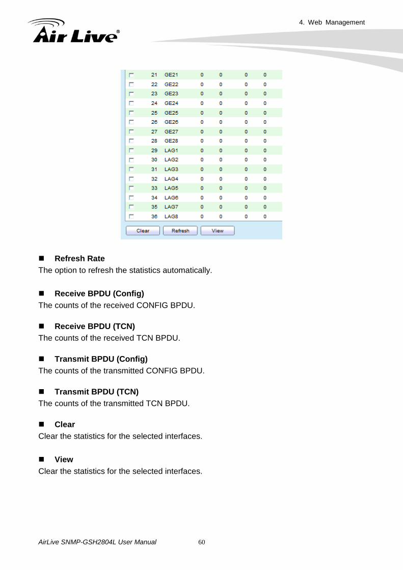
AirLive SNMP-GSH2804L User Manual 60
Refresh Rate The option to refresh the statistics automatically. Receive BPDU (Config) The counts of the received CONFIG BPDU. Receive BPDU (TCN) The counts of the received TCN BPDU. Transmit BPDU (Config) The counts of the transmitted CONFIG BPDU. Transmit BPDU (TCN) The counts of the transmitted TCN BPDU. Clear Clear the statistics for the selected interfaces. View Clear the statistics for the selected interfaces.
4. Web Management
AirLive SNMP-GSH2804L User Manual 61
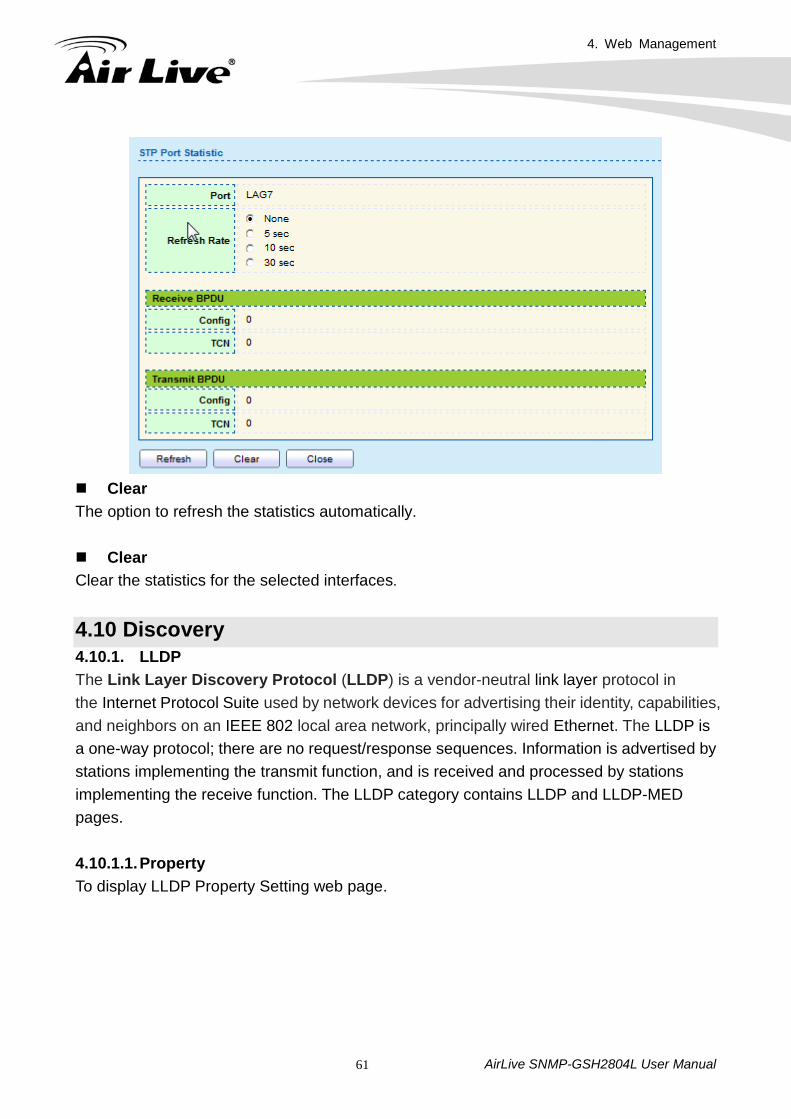
Clear The option to refresh the statistics automatically. Clear Clear the statistics for the selected interfaces.
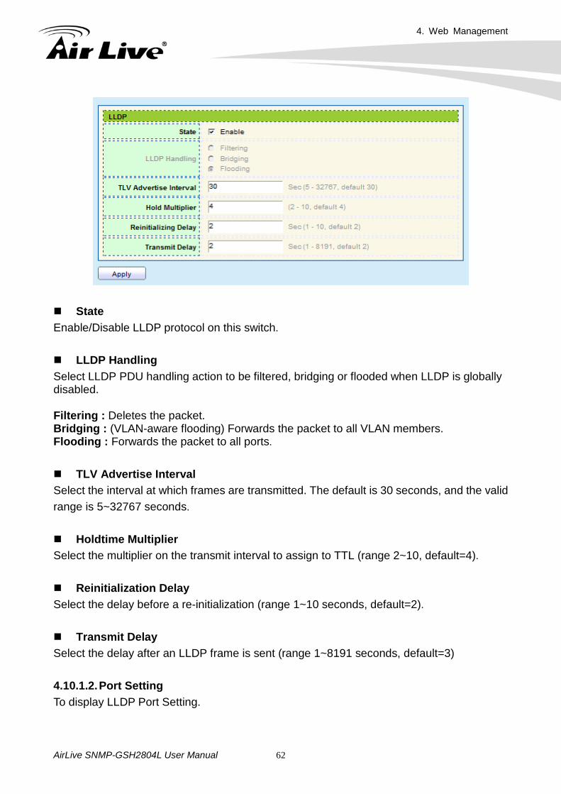
4.10 Discovery 4.10.1. LLDP The Link Layer Discovery Protocol (LLDP) is a vendor-neutral link layer protocol in the Internet Protocol Suite used by network devices for advertising their identity, capabilities, and neighbors on an IEEE 802 local area network, principally wired Ethernet. The LLDP is a one-way protocol; there are no request/response sequences. Information is advertised by stations implementing the transmit function, and is received and processed by stations implementing the receive function. The LLDP category contains LLDP and LLDP-MED pages. 4.10.1.1. Property To display LLDP Property Setting web page.
4. Web Management
AirLive SNMP-GSH2804L User Manual 62
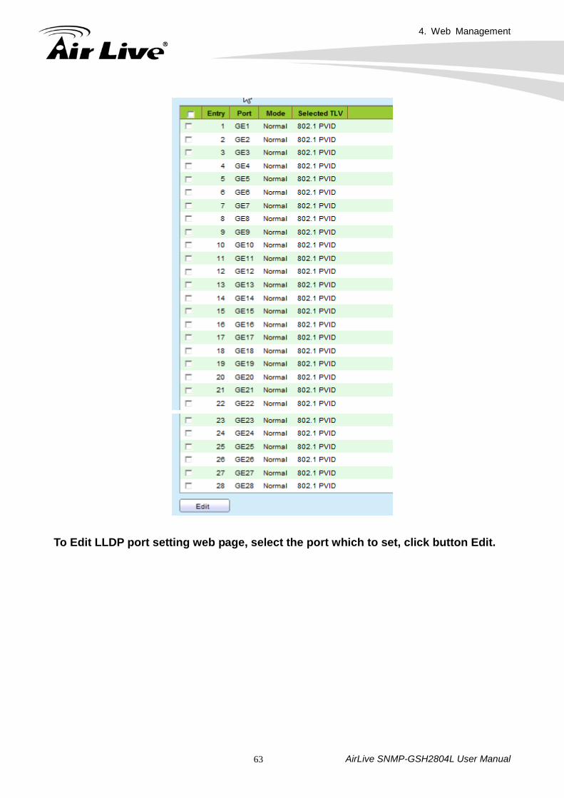
State Enable/Disable LLDP protocol on this switch. LLDP Handling Select LLDP PDU handling action to be filtered, bridging or flooded when LLDP is globally disabled. Filtering : Deletes the packet. Bridging : (VLAN-aware flooding) Forwards the packet to all VLAN members. Flooding : Forwards the packet to all ports. TLV Advertise Interval Select the interval at which frames are transmitted. The default is 30 seconds, and the valid range is 5~32767 seconds. Holdtime Multiplier Select the multiplier on the transmit interval to assign to TTL (range 2~10, default=4). Reinitialization Delay Select the delay before a re-initialization (range 1~10 seconds, default=2). Transmit Delay Select the delay after an LLDP frame is sent (range 1~8191 seconds, default=3) 4.10.1.2. Port Setting To display LLDP Port Setting.
4. Web Management
AirLive SNMP-GSH2804L User Manual 63
To Edit LLDP port setting web page, select the port which to set, click button Edit.
4. Web Management
AirLive SNMP-GSH2804L User Manual 64
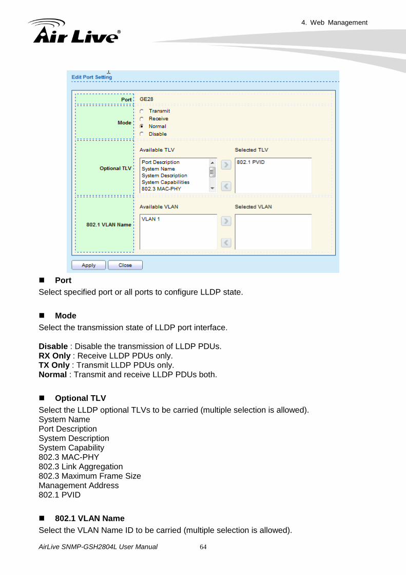
Port Select specified port or all ports to configure LLDP state. Mode Select the transmission state of LLDP port interface. Disable : Disable the transmission of LLDP PDUs. RX Only : Receive LLDP PDUs only. TX Only : Transmit LLDP PDUs only. Normal : Transmit and receive LLDP PDUs both. Optional TLV Select the LLDP optional TLVs to be carried (multiple selection is allowed). System Name Port Description System Description System Capability 802.3 MAC-PHY 802.3 Link Aggregation 802.3 Maximum Frame Size Management Address 802.1 PVID
802.1 VLAN Name Select the VLAN Name ID to be carried (multiple selection is allowed).
4. Web Management
AirLive SNMP-GSH2804L User Manual 65
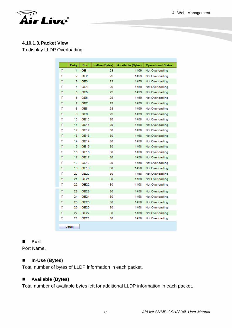
4.10.1.3. Packet View To display LLDP Overloading.
Port Port Name. In-Use (Bytes) Total number of bytes of LLDP information in each packet. Available (Bytes) Total number of available bytes left for additional LLDP information in each packet.
4. Web Management
AirLive SNMP-GSH2804L User Manual 66
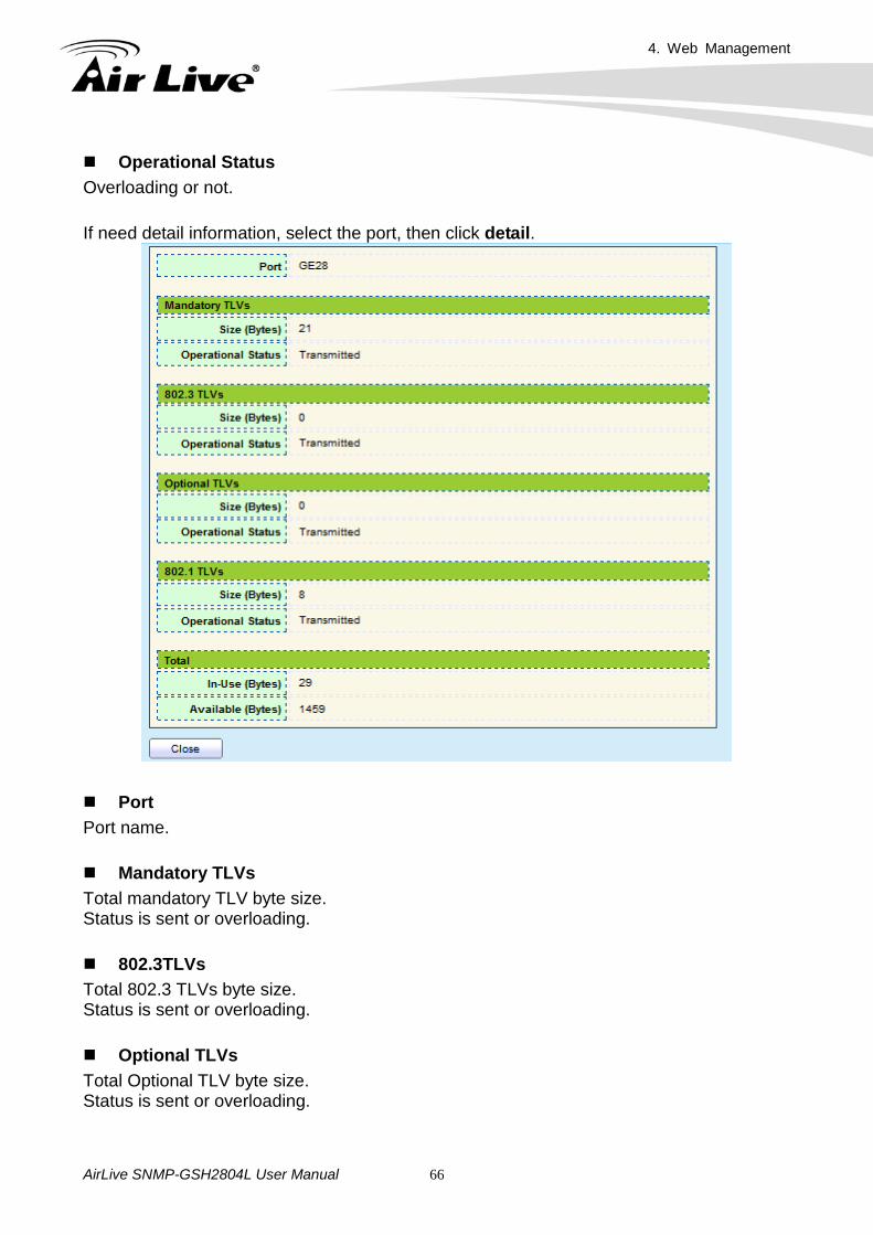
Operational Status Overloading or not. If need detail information, select the port, then click detail.
Port Port name. Mandatory TLVs Total mandatory TLV byte size. Status is sent or overloading. 802.3TLVs Total 802.3 TLVs byte size. Status is sent or overloading. Optional TLVs Total Optional TLV byte size. Status is sent or overloading.
4. Web Management
AirLive SNMP-GSH2804L User Manual 67
802.1 TLVs Total 802.1 TLVs byte size. Status is sent or overloading. Total Total number of bytes of LLDP information in each packet. 4.10.1.4. Local Information
To display LLDP Local Device.
4. Web Management
AirLive SNMP-GSH2804L User Manual 68
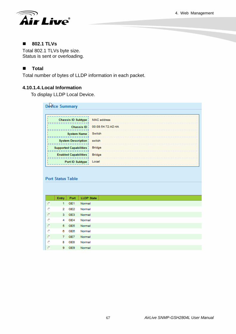
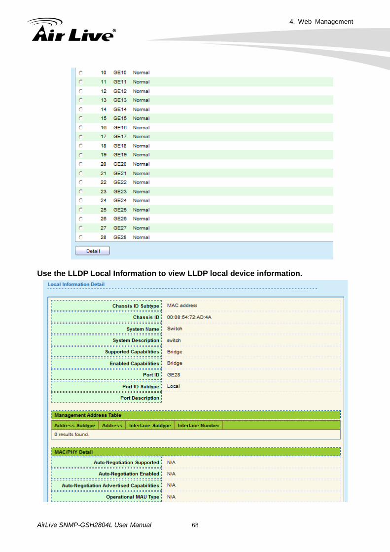
Use the LLDP Local Information to view LLDP local device information.
4. Web Management
AirLive SNMP-GSH2804L User Manual 69
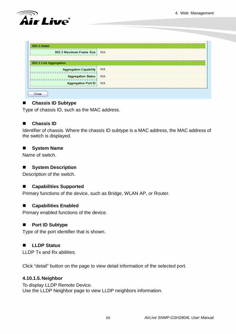
Chassis ID Subtype Type of chassis ID, such as the MAC address. Chassis ID Identifier of chassis. Where the chassis ID subtype is a MAC address, the MAC address of the switch is displayed. System Name Name of switch. System Description Description of the switch. Capabilities Supported Primary functions of the device, such as Bridge, WLAN AP, or Router. Capabilities Enabled Primary enabled functions of the device. Port ID Subtype Type of the port identifier that is shown. LLDP Status LLDP Tx and Rx abilities. Click “detail” button on the page to view detail information of the selected port. 4.10.1.5. Neighbor To display LLDP Remote Device. Use the LLDP Neighbor page to view LLDP neighbors information.
4. Web Management
AirLive SNMP-GSH2804L User Manual 70
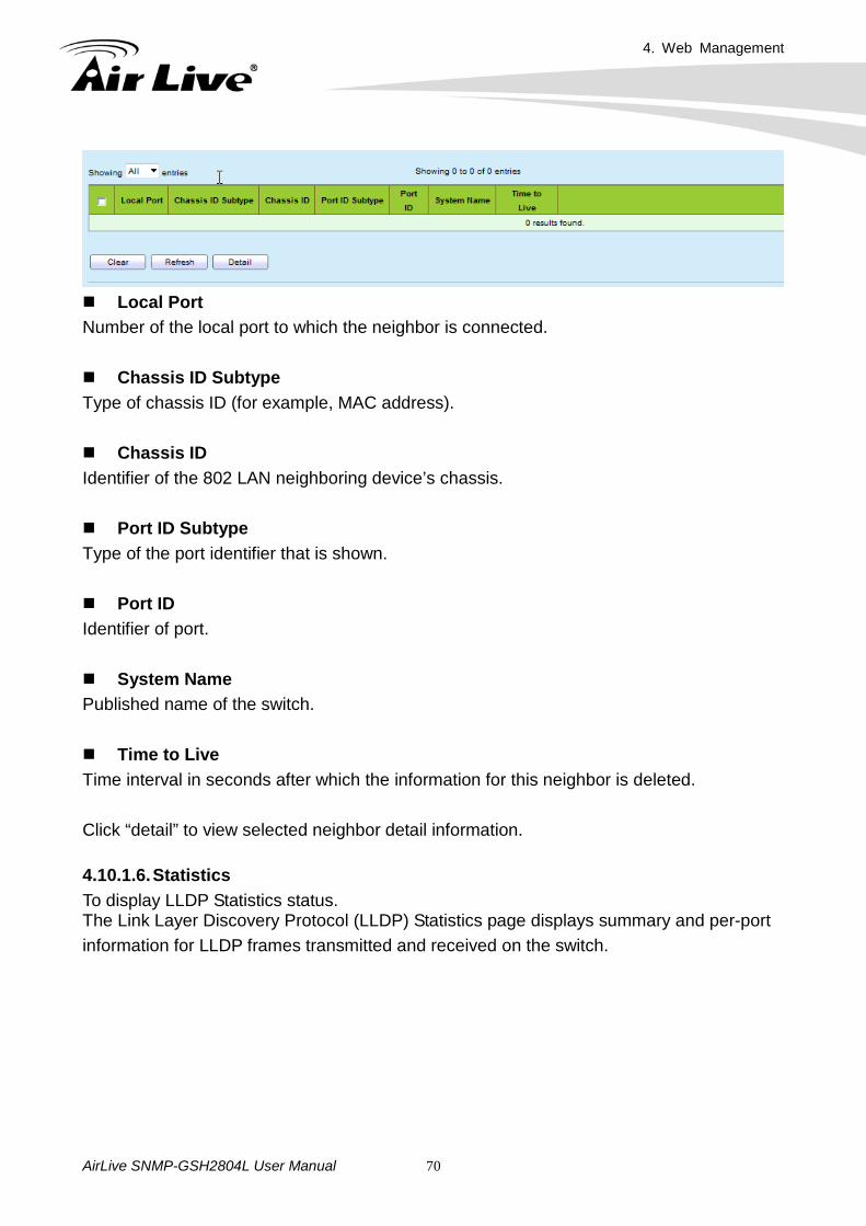
Local Port Number of the local port to which the neighbor is connected. Chassis ID Subtype Type of chassis ID (for example, MAC address). Chassis ID Identifier of the 802 LAN neighboring device’s chassis. Port ID Subtype Type of the port identifier that is shown. Port ID Identifier of port. System Name Published name of the switch. Time to Live Time interval in seconds after which the information for this neighbor is deleted. Click “detail” to view selected neighbor detail information. 4.10.1.6. Statistics To display LLDP Statistics status. The Link Layer Discovery Protocol (LLDP) Statistics page displays summary and per-port information for LLDP frames transmitted and received on the switch.
4. Web Management
AirLive SNMP-GSH2804L User Manual 71
4. Web Management
AirLive SNMP-GSH2804L User Manual 72
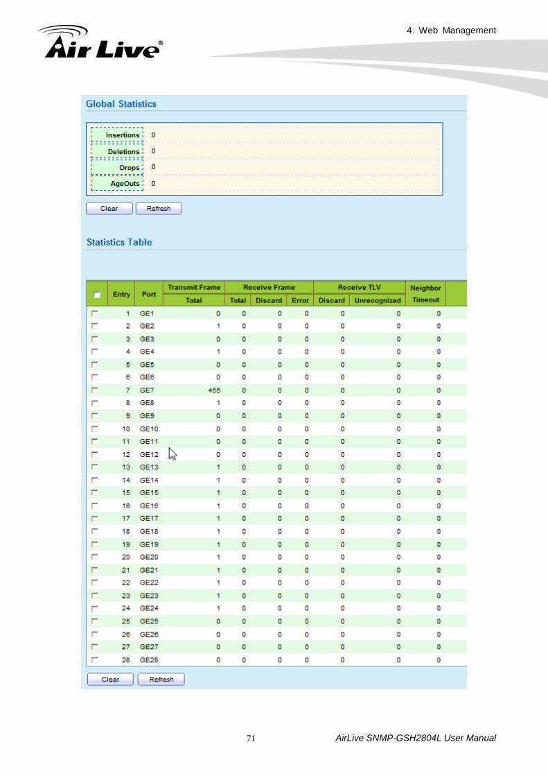
Insertions The number of times the complete set of information advertised by a particular MAC Service Access Point (MSAP) has been inserted into tables associated with the remote systems. Deletions The number of times the complete set of information advertised by MSAP has been deleted from tables associated with the remote systems. Drops The number of times the complete set of information advertised by MSAP could not be entered into tables associated with the remote systems because of insufficient resources. Age Outs The number of times the complete set of information advertised by MSAP has been deleted from tables associated with the remote system because the information timeliness interval has expired. Port Interface or port number. Transmit Frame Total Number of LLDP frames transmitted on the corresponding port. Receive Frame Total Number of LLDP frames received by this LLDP agent on the corresponding port, while the LLDP agent is enabled.
Receive Frame Discard Number of LLDP frames discarded for any reason by the LLDP agent on the corresponding port. Receive Frame Error Number of invalid LLDP frames received by the LLDP agent on the corresponding port, while the LLDP agent is enabled.
Receive TLV Discard Number of TLVs of LLDP frames discarded for any reason by the LLDP agent on the corresponding port.
4. Web Management
AirLive SNMP-GSH2804L User Manual 73
Receive TLV Unrecognized Number of TLVs of LLDP frames that are unrecognized while the LLDP agent is enabled.
Neighbor Timeout Number of age out LLDP frames.
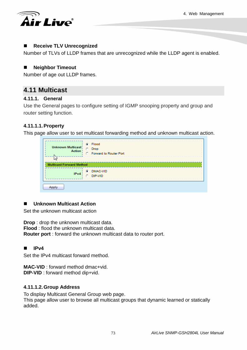
4.11 Multicast 4.11.1. General Use the General pages to configure setting of IGMP snooping property and group and router setting function. 4.11.1.1. Property This page allow user to set multicast forwarding method and unknown multicast action.
Unknown Multicast Action Set the unknown multicast action Drop : drop the unknown multicast data. Flood : flood the unknown multicast data. Router port : forward the unknown multicast data to router port. IPv4 Set the IPv4 multicast forward method. MAC-VID : forward method dmac+vid. DIP-VID : forward method dip+vid. 4.11.1.2. Group Address To display Multicast General Group web page. This page allow user to browse all multicast groups that dynamic learned or statically added.
4. Web Management
AirLive SNMP-GSH2804L User Manual 74
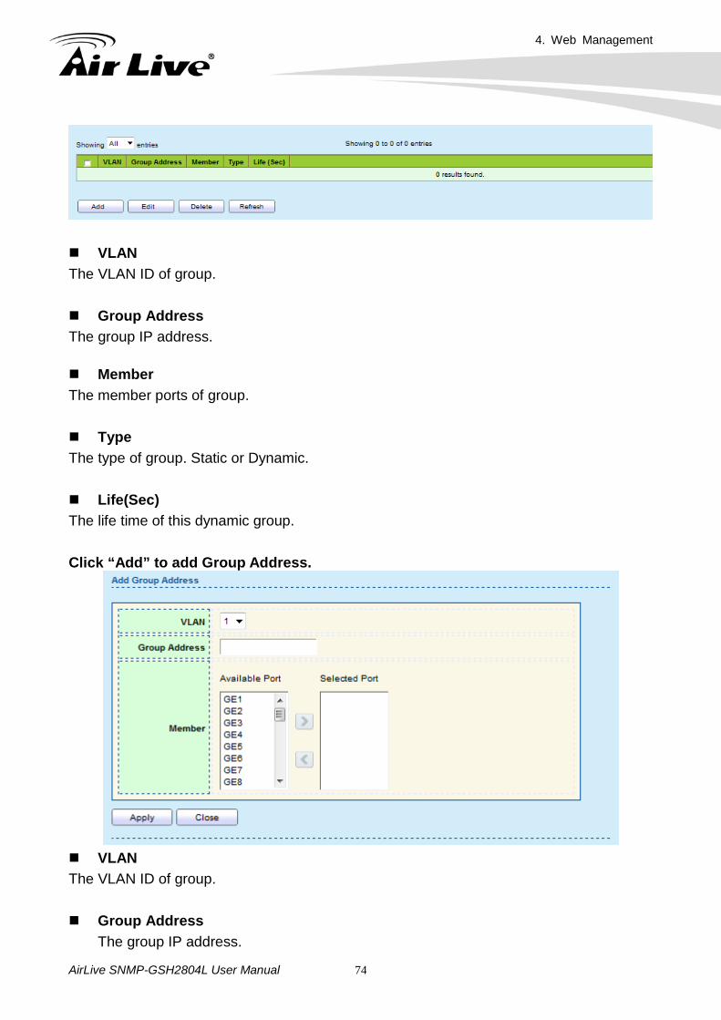
VLAN The VLAN ID of group. Group Address The group IP address. Member The member ports of group. Type The type of group. Static or Dynamic. Life(Sec) The life time of this dynamic group. Click “Add” to add Group Address.
VLAN The VLAN ID of group. Group Address
The group IP address.
4. Web Management
AirLive SNMP-GSH2804L User Manual 75
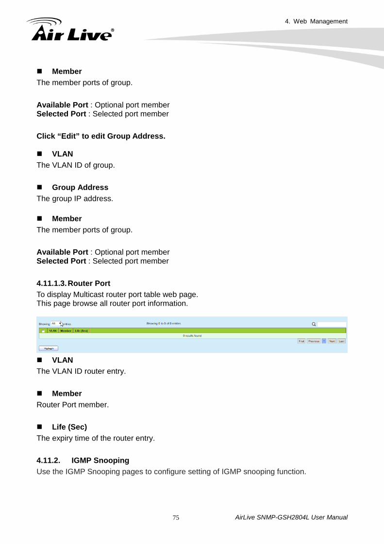
Member The member ports of group. Available Port : Optional port member Selected Port : Selected port member Click “Edit” to edit Group Address. VLAN The VLAN ID of group. Group Address The group IP address. Member The member ports of group. Available Port : Optional port member Selected Port : Selected port member 4.11.1.3. Router Port To display Multicast router port table web page. This page browse all router port information.
VLAN The VLAN ID router entry. Member Router Port member. Life (Sec) The expiry time of the router entry. 4.11.2. IGMP Snooping Use the IGMP Snooping pages to configure setting of IGMP snooping function.
4. Web Management
AirLive SNMP-GSH2804L User Manual 76
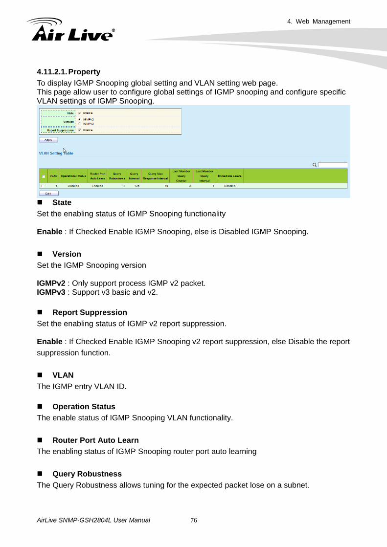
4.11.2.1. Property To display IGMP Snooping global setting and VLAN setting web page. This page allow user to configure global settings of IGMP snooping and configure specific VLAN settings of IGMP Snooping.
State Set the enabling status of IGMP Snooping functionality
Enable : If Checked Enable IGMP Snooping, else is Disabled IGMP Snooping. Version Set the IGMP Snooping version
IGMPv2 : Only support process IGMP v2 packet. IGMPv3 : Support v3 basic and v2. Report Suppression Set the enabling status of IGMP v2 report suppression.
Enable : If Checked Enable IGMP Snooping v2 report suppression, else Disable the report suppression function.
VLAN The IGMP entry VLAN ID. Operation Status The enable status of IGMP Snooping VLAN functionality.
Router Port Auto Learn The enabling status of IGMP Snooping router port auto learning Query Robustness The Query Robustness allows tuning for the expected packet lose on a subnet.
4. Web Management
AirLive SNMP-GSH2804L User Manual 77
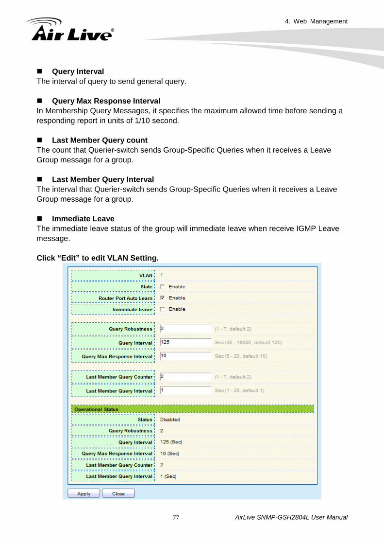
Query Interval The interval of query to send general query. Query Max Response Interval In Membership Query Messages, it specifies the maximum allowed time before sending a responding report in units of 1/10 second. Last Member Query count The count that Querier-switch sends Group-Specific Queries when it receives a Leave Group message for a group. Last Member Query Interval The interval that Querier-switch sends Group-Specific Queries when it receives a Leave Group message for a group. Immediate Leave The immediate leave status of the group will immediate leave when receive IGMP Leave message. Click “Edit” to edit VLAN Setting.
4. Web Management
AirLive SNMP-GSH2804L User Manual 78
VLAN The selected VLAN List State Set the enabling status of IGMP Snooping VLAN functionality
Enable : If Checked Enable IGMP Snooping router VLAN, else is Disabled IGMP Snooping VLAN. Router Port Auto Learn Set the enabling status of IGMP Snooping router port learning.
Enable : If Checked Enable learning router port by query and PIM, DVRMP, else Disable the learning router port.
Immediate Leave Immediate Leave the group when receive IGMP Leave message.
Enable : If Checked Enable immediate leave, else Disable immediate leave. Query Robustness The Admin Query Robustness allows tuning for the expected packet loss on a subnet. Query Interval The Admin interval of querier to send general query. Query Max Response Interval The Admin query max response interval, In Membership Query Messages, it specifies the maximum allowed time before sending a responding report in units of 1/10 second. Last Member Query Counter The Admin last member query count that Querier-switch sends Group-Specific Queries when it receives a Leave Group message for a group. Last Member Query Interval The Admin last member query interval that Querier-switch sends Group-Specific Queries when it receives a Leave Group message for a group. Operational Status. Status Operational IGMP Snooping status, must both IGMP Snooping global and IGMP Snooping enable the status will be enable.
4. Web Management
AirLive SNMP-GSH2804L User Manual 79
Query Robustness Operational Query Robustness.
Query Interval Operational Query Interval.
Query Max Response Interval Operational Query Max Response Interval. Last Member Query Counter Operational Last Member Query Count.
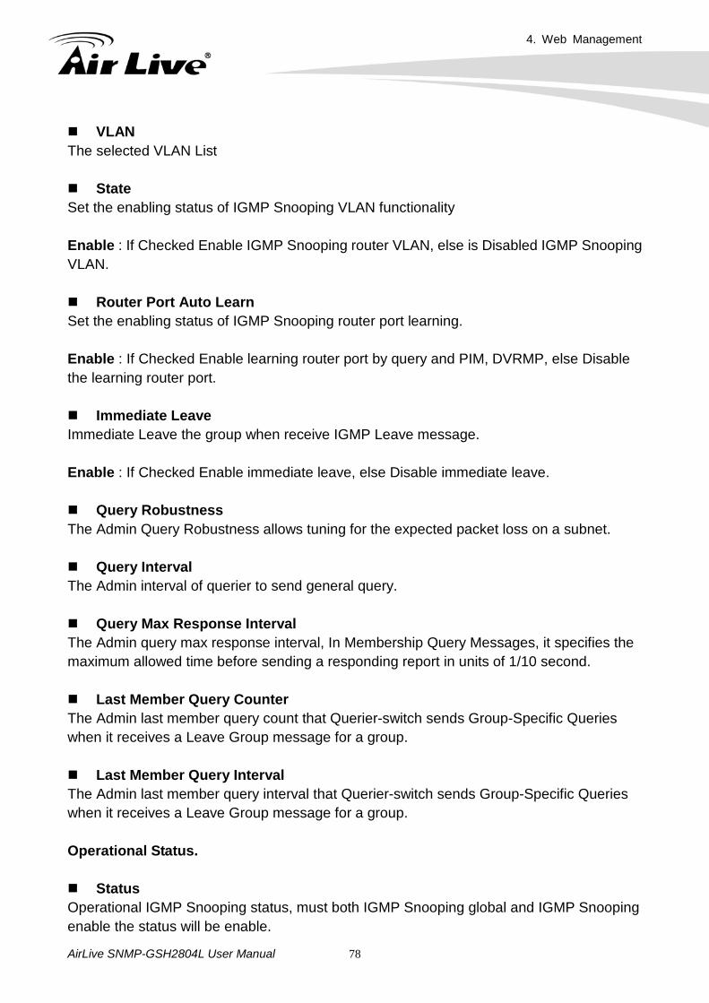
Last Member Query Interval Operational Last Member Query Interval. 4.11.2.2. Querier To display IGMP Snooping Querier setting web page. This page allow user to configure querier setting on specific VLAN of IGMP Snooping.
VLAN IGMP Snooping querier entry VLAN ID. State The IGMP Snooping querier Admin State.
Operational Status The IGMP Snooping querier operational status. Querier Version The IGMP Snooping querier operational version. Querier IP The operational querier IP address on the VLAN.
4. Web Management
AirLive SNMP-GSH2804L User Manual 80
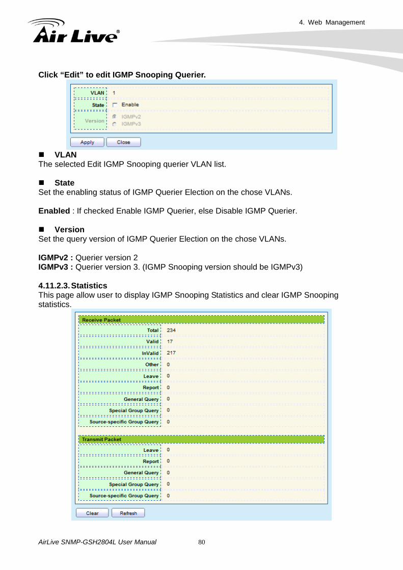
Click “Edit” to edit IGMP Snooping Querier.
VLAN The selected Edit IGMP Snooping querier VLAN list. State Set the enabling status of IGMP Querier Election on the chose VLANs.
Enabled : If checked Enable IGMP Querier, else Disable IGMP Querier. Version Set the query version of IGMP Querier Election on the chose VLANs.
IGMPv2 : Querier version 2 IGMPv3 : Querier version 3. (IGMP Snooping version should be IGMPv3) 4.11.2.3. Statistics This page allow user to display IGMP Snooping Statistics and clear IGMP Snooping statistics.

4. Web Management
AirLive SNMP-GSH2804L User Manual 81
Receive Packet Total Total RX IGMP packet, include IPv4 multicast data to CPU.
Valid The valid IGMP Snooping process packet.
InValid The invalid IGMP Snooping process packet. Other The ICMP protocol is not 2, and is not IPv4 multicast data packet. Leave IGMP leave packet. Report IGMP join and report packet. General Query IGMP general query packet Special Group Query IGMP special group general query packet Source-specific Group Query IGMP special source and group general query packet Transmit Packet Leave IGMP leave packet Report IGMP join and report packet General Query IGMP general query packet includes querier transmit general query packet. Special Group Query IGMP special group query packet include querier transmit special group query packet.
4. Web Management
AirLive SNMP-GSH2804L User Manual 82
Source-specific Group Query IGMP special source and group general query packet.
4.12 Security 4.12.1. Management Access Use the Management Access pages to configure setting of management access. 4.12.1.1. Management VLAN This page allow user to change Management VLAN connection.
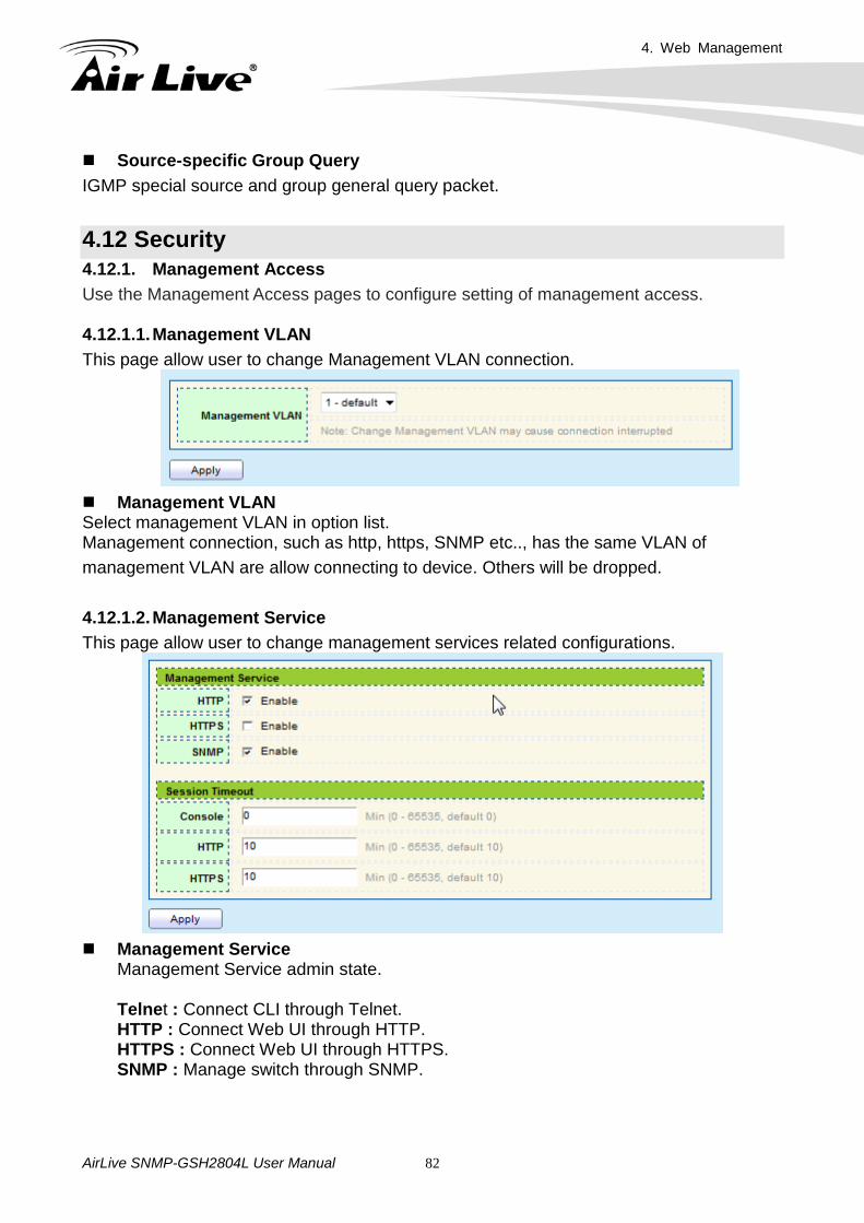
Management VLAN Select management VLAN in option list. Management connection, such as http, https, SNMP etc.., has the same VLAN of management VLAN are allow connecting to device. Others will be dropped. 4.12.1.2. Management Service This page allow user to change management services related configurations.
Management Service
Management Service admin state. Telnet : Connect CLI through Telnet. HTTP : Connect Web UI through HTTP. HTTPS : Connect Web UI through HTTPS. SNMP : Manage switch through SNMP.
4. Web Management
AirLive SNMP-GSH2804L User Manual 83
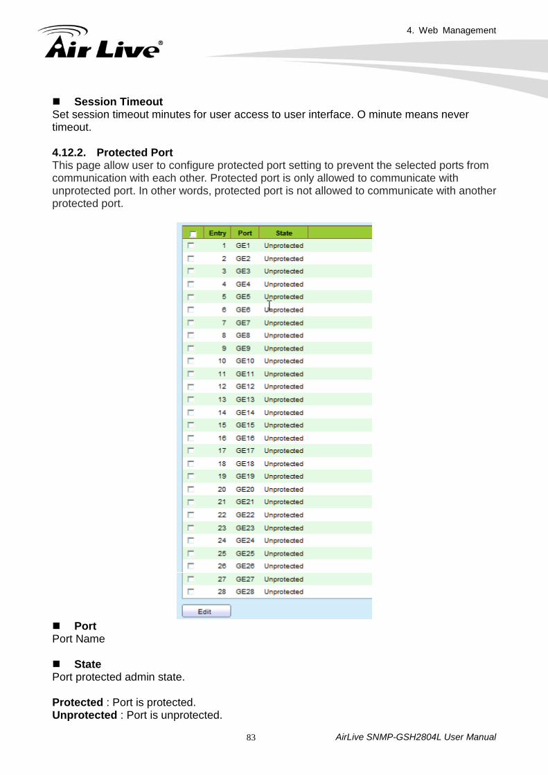
Session Timeout Set session timeout minutes for user access to user interface. O minute means never timeout. 4.12.2. Protected Port This page allow user to configure protected port setting to prevent the selected ports from communication with each other. Protected port is only allowed to communicate with unprotected port. In other words, protected port is not allowed to communicate with another protected port.
Port Port Name State Port protected admin state.
Protected : Port is protected. Unprotected : Port is unprotected.
4. Web Management
AirLive SNMP-GSH2804L User Manual 84
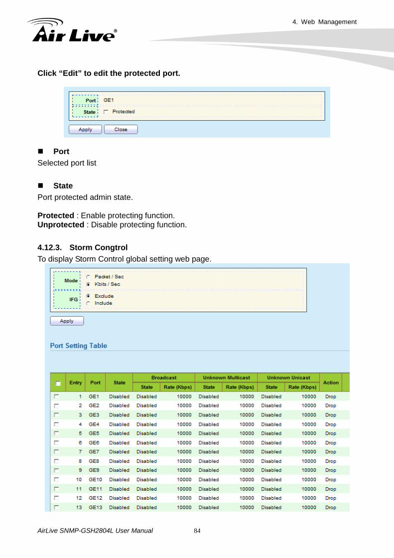
Click “Edit” to edit the protected port.
Port Selected port list State Port protected admin state. Protected : Enable protecting function. Unprotected : Disable protecting function. 4.12.3. Storm Congtrol To display Storm Control global setting web page.
4. Web Management
AirLive SNMP-GSH2804L User Manual 85
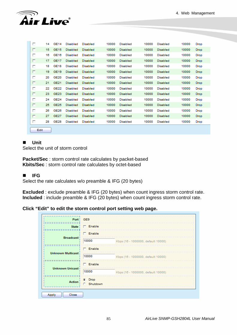
Unit Select the unit of storm control Packet/Sec : storm control rate calculates by packet-based Kbits/Sec : storm control rate calculates by octet-based
IFG Select the rate calculates w/o preamble & IFG (20 bytes)
Excluded : exclude preamble & IFG (20 bytes) when count ingress storm control rate. Included : include preamble & IFG (20 bytes) when count ingress storm control rate. Click “Edit” to edit the storm control port setting web page.
4. Web Management
AirLive SNMP-GSH2804L User Manual 86
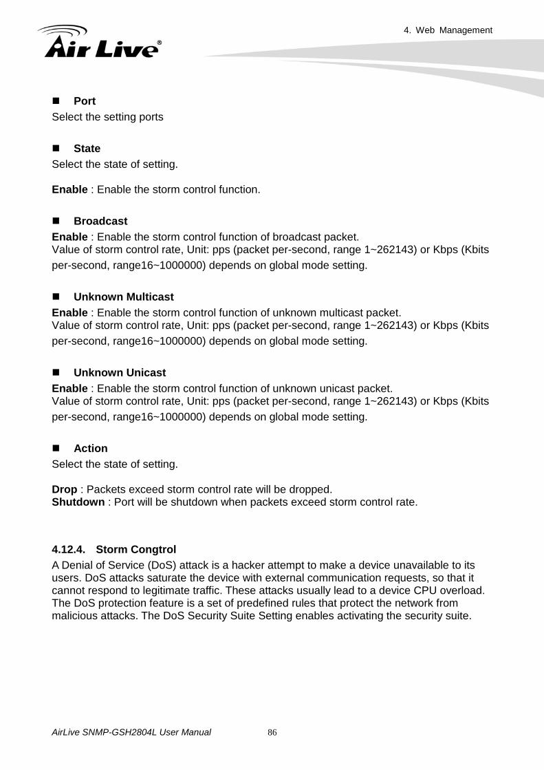
Port Select the setting ports State Select the state of setting. Enable : Enable the storm control function.
Broadcast Enable : Enable the storm control function of broadcast packet. Value of storm control rate, Unit: pps (packet per-second, range 1~262143) or Kbps (Kbits per-second, range16~1000000) depends on global mode setting.
Unknown Multicast Enable : Enable the storm control function of unknown multicast packet. Value of storm control rate, Unit: pps (packet per-second, range 1~262143) or Kbps (Kbits per-second, range16~1000000) depends on global mode setting.
Unknown Unicast Enable : Enable the storm control function of unknown unicast packet. Value of storm control rate, Unit: pps (packet per-second, range 1~262143) or Kbps (Kbits per-second, range16~1000000) depends on global mode setting. Action Select the state of setting. Drop : Packets exceed storm control rate will be dropped. Shutdown : Port will be shutdown when packets exceed storm control rate. 4.12.4. Storm Congtrol A Denial of Service (DoS) attack is a hacker attempt to make a device unavailable to its users. DoS attacks saturate the device with external communication requests, so that it cannot respond to legitimate traffic. These attacks usually lead to a device CPU overload. The DoS protection feature is a set of predefined rules that protect the network from malicious attacks. The DoS Security Suite Setting enables activating the security suite.
4. Web Management
AirLive SNMP-GSH2804L User Manual 87
4.12.4.1. Property
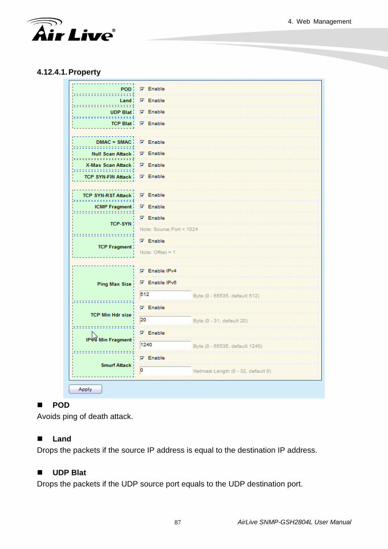
POD Avoids ping of death attack. Land Drops the packets if the source IP address is equal to the destination IP address. UDP Blat Drops the packets if the UDP source port equals to the UDP destination port.
4. Web Management
AirLive SNMP-GSH2804L User Manual 88
TCP Blat Drops the packages if the TCP source port is equal to the TCP destination port. DMAC=SMAC Drops the packets if the destination MAC address is equal to the source MAC address. Null Scan Attack Drops the packets with NULL scan. X-Mas Scan Attack Drops the packets if the sequence number is zero, and the FIN, URG and PSH bits are set. TCP SYN-FIN Attack Drops the packets with SYN and FIN bits set. TCP SYN-RST Attack Drops the packets with SYN and RST bits set. ICMP Flagment Drops the fragmented ICMP packets.
TCP-SYN(SPORT<1024) Drops SYN packets with sport less than 1024. TCP Fragment (Offset=1) Drops the TCP fragment packets with offset equals to one. Ping Max Size Specify the maximum size of the ICMPv4/ICMPv6 ping packets. The valid range is from 0 to 65535 bytes, and the default value is 512 bytes. IPv4 Ping Max Size Checks the maximum size of ICMP ping packets, and drops the packets larger than the maximum packet size. IPv6 Ping Max Size Checks the maximum size of ICMPv6 ping packets, and drops the packets larger than the maximum packet size
4. Web Management
AirLive SNMP-GSH2804L User Manual 89
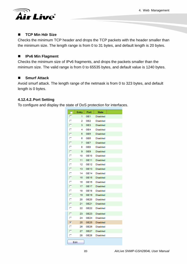
TCP Min Hdr Size Checks the minimum TCP header and drops the TCP packets with the header smaller than the minimum size. The length range is from 0 to 31 bytes, and default length is 20 bytes. IPv6 Min Flagment Checks the minimum size of IPv6 fragments, and drops the packets smaller than the minimum size. The valid range is from 0 to 65535 bytes, and default value is 1240 bytes. Smurf Attack Avoid smurf attack. The length range of the netmask is from 0 to 323 bytes, and default length is 0 bytes. 4.12.4.2. Port Setting To configure and display the state of DoS protection for interfaces.
4. Web Management
AirLive SNMP-GSH2804L User Manual 90
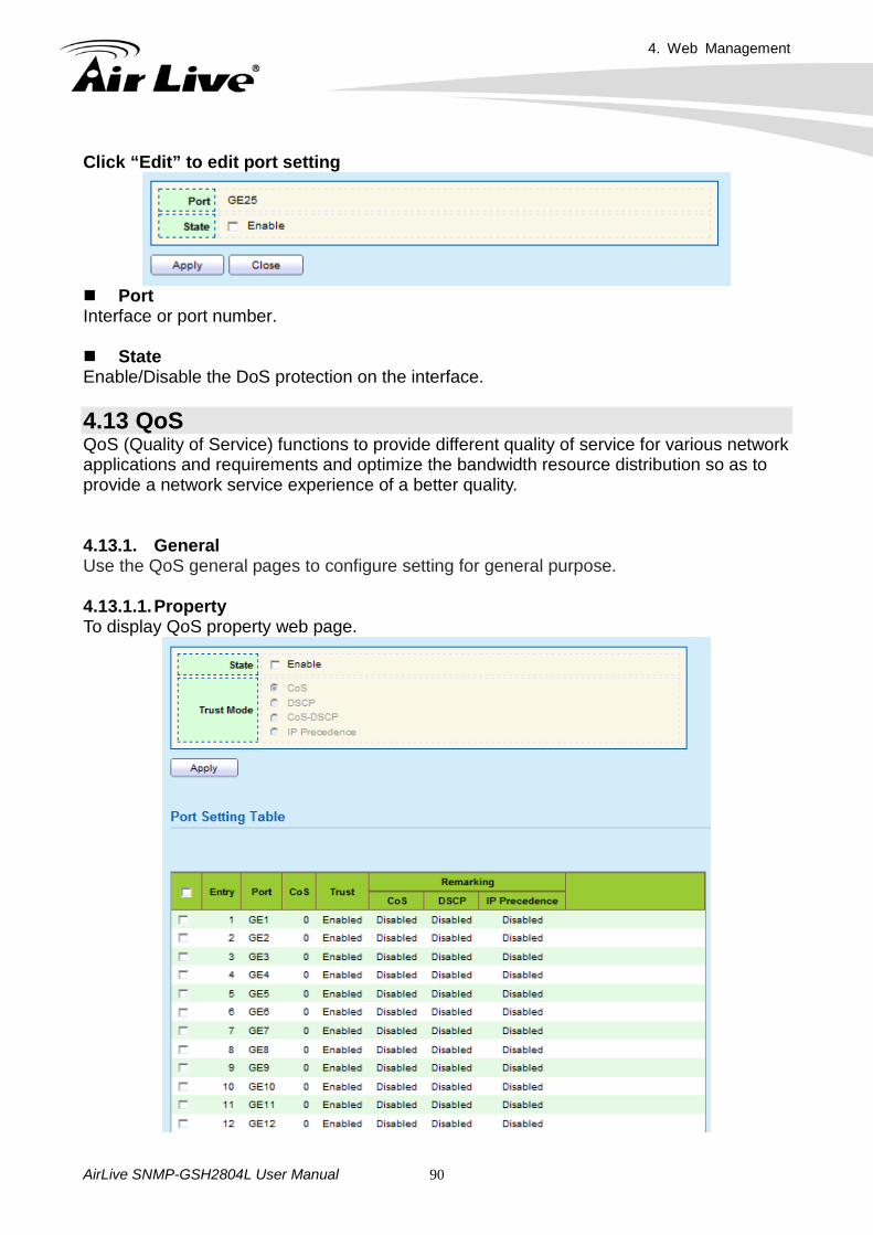
Click “Edit” to edit port setting
Port Interface or port number. State Enable/Disable the DoS protection on the interface. 4.13 QoS QoS (Quality of Service) functions to provide different quality of service for various network applications and requirements and optimize the bandwidth resource distribution so as to provide a network service experience of a better quality. 4.13.1. General Use the QoS general pages to configure setting for general purpose. 4.13.1.1. Property To display QoS property web page.
4. Web Management
AirLive SNMP-GSH2804L User Manual 91
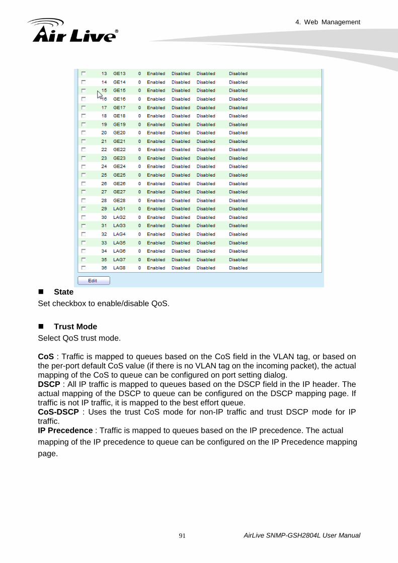
State Set checkbox to enable/disable QoS. Trust Mode Select QoS trust mode. CoS : Traffic is mapped to queues based on the CoS field in the VLAN tag, or based on the per-port default CoS value (if there is no VLAN tag on the incoming packet), the actual mapping of the CoS to queue can be configured on port setting dialog. DSCP : All IP traffic is mapped to queues based on the DSCP field in the IP header. The actual mapping of the DSCP to queue can be configured on the DSCP mapping page. If traffic is not IP traffic, it is mapped to the best effort queue. CoS-DSCP : Uses the trust CoS mode for non-IP traffic and trust DSCP mode for IP traffic. IP Precedence : Traffic is mapped to queues based on the IP precedence. The actual mapping of the IP precedence to queue can be configured on the IP Precedence mapping page.
4. Web Management
AirLive SNMP-GSH2804L User Manual 92
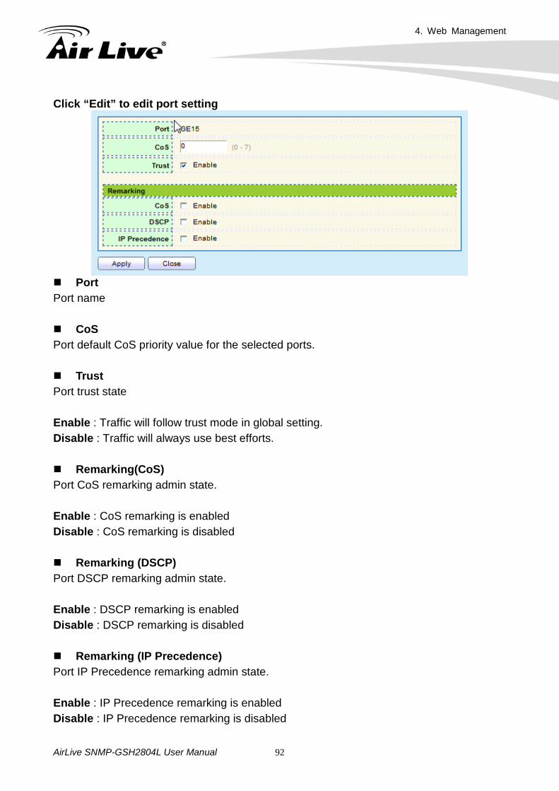
Click “Edit” to edit port setting
Port Port name CoS Port default CoS priority value for the selected ports. Trust Port trust state
Enable : Traffic will follow trust mode in global setting. Disable : Traffic will always use best efforts. Remarking(CoS) Port CoS remarking admin state.
Enable : CoS remarking is enabled Disable : CoS remarking is disabled Remarking (DSCP) Port DSCP remarking admin state.
Enable : DSCP remarking is enabled Disable : DSCP remarking is disabled Remarking (IP Precedence) Port IP Precedence remarking admin state.
Enable : IP Precedence remarking is enabled Disable : IP Precedence remarking is disabled
4. Web Management
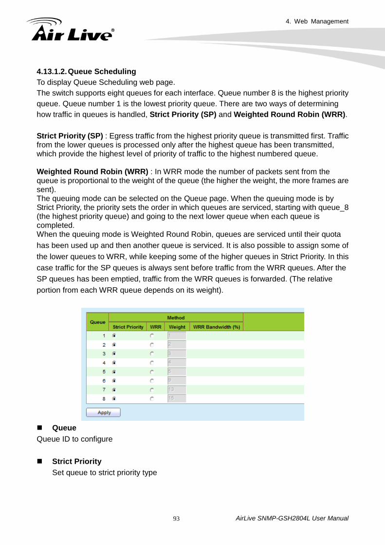
AirLive SNMP-GSH2804L User Manual 93
4.13.1.2. Queue Scheduling To display Queue Scheduling web page. The switch supports eight queues for each interface. Queue number 8 is the highest priority queue. Queue number 1 is the lowest priority queue. There are two ways of determining how traffic in queues is handled, Strict Priority (SP) and Weighted Round Robin (WRR). Strict Priority (SP) : Egress traffic from the highest priority queue is transmitted first. Traffic from the lower queues is processed only after the highest queue has been transmitted, which provide the highest level of priority of traffic to the highest numbered queue. Weighted Round Robin (WRR) : In WRR mode the number of packets sent from the queue is proportional to the weight of the queue (the higher the weight, the more frames are sent). The queuing mode can be selected on the Queue page. When the queuing mode is by Strict Priority, the priority sets the order in which queues are serviced, starting with queue_8 (the highest priority queue) and going to the next lower queue when each queue is completed. When the queuing mode is Weighted Round Robin, queues are serviced until their quota has been used up and then another queue is serviced. It is also possible to assign some of the lower queues to WRR, while keeping some of the higher queues in Strict Priority. In this case traffic for the SP queues is always sent before traffic from the WRR queues. After the SP queues has been emptied, traffic from the WRR queues is forwarded. (The relative portion from each WRR queue depends on its weight).
Queue Queue ID to configure Strict Priority
Set queue to strict priority type
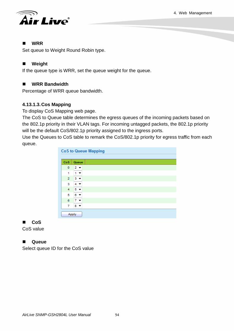
4. Web Management
AirLive SNMP-GSH2804L User Manual 94
WRR Set queue to Weight Round Robin type. Weight If the queue type is WRR, set the queue weight for the queue. WRR Bandwidth Percentage of WRR queue bandwidth. 4.13.1.3. Cos Mapping To display CoS Mapping web page. The CoS to Queue table determines the egress queues of the incoming packets based on the 802.1p priority in their VLAN tags. For incoming untagged packets, the 802.1p priority will be the default CoS/802.1p priority assigned to the ingress ports. Use the Queues to CoS table to remark the CoS/802.1p priority for egress traffic from each queue.
CoS CoS value Queue Select queue ID for the CoS value
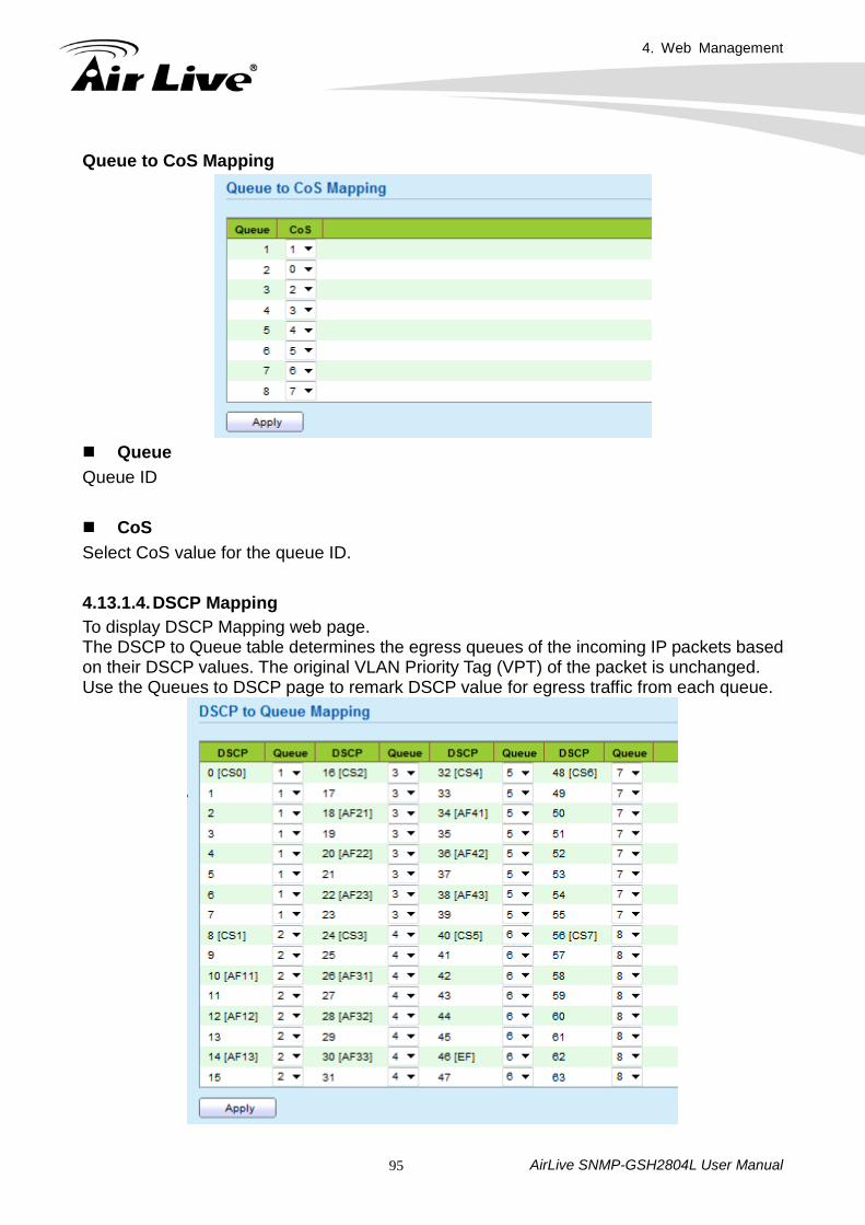
4. Web Management
AirLive SNMP-GSH2804L User Manual 95
Queue to CoS Mapping
Queue Queue ID CoS Select CoS value for the queue ID. 4.13.1.4. DSCP Mapping To display DSCP Mapping web page. The DSCP to Queue table determines the egress queues of the incoming IP packets based on their DSCP values. The original VLAN Priority Tag (VPT) of the packet is unchanged. Use the Queues to DSCP page to remark DSCP value for egress traffic from each queue.
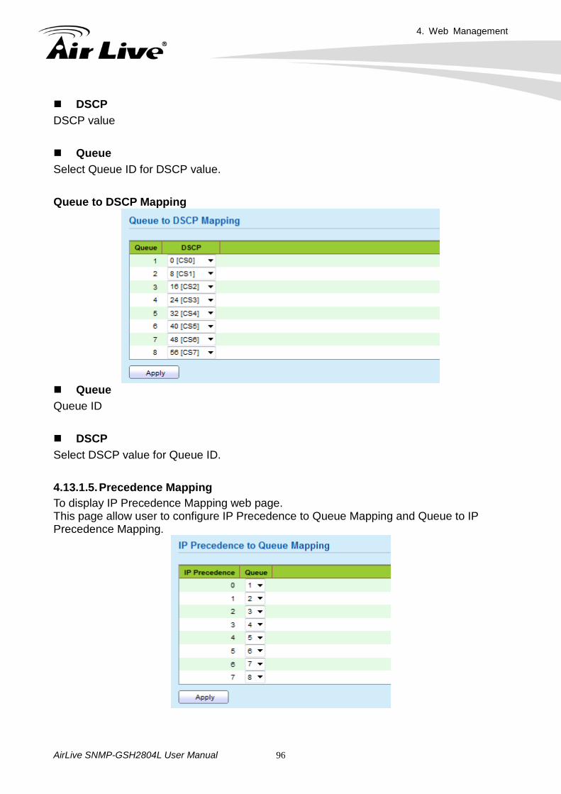
4. Web Management
AirLive SNMP-GSH2804L User Manual 96
DSCP DSCP value Queue Select Queue ID for DSCP value. Queue to DSCP Mapping
Queue Queue ID DSCP Select DSCP value for Queue ID. 4.13.1.5. Precedence Mapping To display IP Precedence Mapping web page. This page allow user to configure IP Precedence to Queue Mapping and Queue to IP Precedence Mapping.
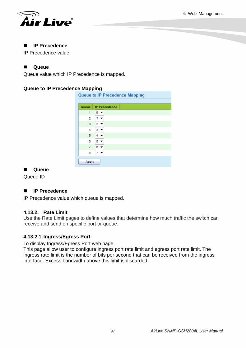
4. Web Management
AirLive SNMP-GSH2804L User Manual 97
IP Precedence IP Precedence value Queue Queue value which IP Precedence is mapped. Queue to IP Precedence Mapping
Queue Queue ID IP Precedence IP Precedence value which queue is mapped. 4.13.2. Rate Limit Use the Rate Limit pages to define values that determine how much traffic the switch can receive and send on specific port or queue. 4.13.2.1. Ingress/Egress Port To display Ingress/Egress Port web page. This page allow user to configure ingress port rate limit and egress port rate limit. The ingress rate limit is the number of bits per second that can be received from the ingress interface. Excess bandwidth above this limit is discarded.
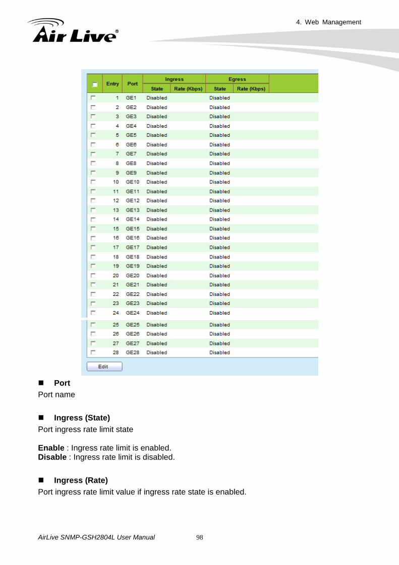
4. Web Management
AirLive SNMP-GSH2804L User Manual 98
Port Port name Ingress (State) Port ingress rate limit state
Enable : Ingress rate limit is enabled. Disable : Ingress rate limit is disabled. Ingress (Rate) Port ingress rate limit value if ingress rate state is enabled.
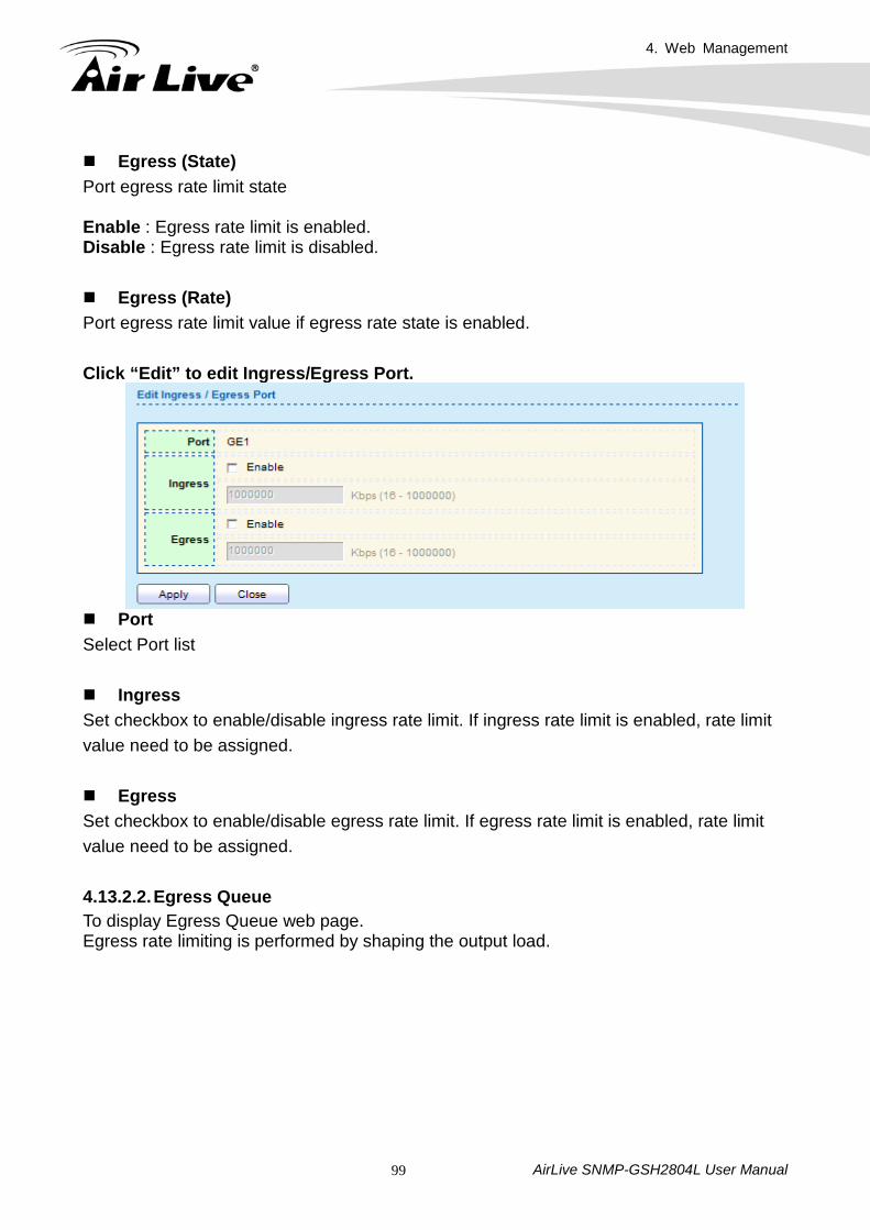
4. Web Management
AirLive SNMP-GSH2804L User Manual 99
Egress (State) Port egress rate limit state
Enable : Egress rate limit is enabled. Disable : Egress rate limit is disabled. Egress (Rate) Port egress rate limit value if egress rate state is enabled. Click “Edit” to edit Ingress/Egress Port.
Port Select Port list Ingress Set checkbox to enable/disable ingress rate limit. If ingress rate limit is enabled, rate limit value need to be assigned. Egress Set checkbox to enable/disable egress rate limit. If egress rate limit is enabled, rate limit value need to be assigned. 4.13.2.2. Egress Queue To display Egress Queue web page. Egress rate limiting is performed by shaping the output load.
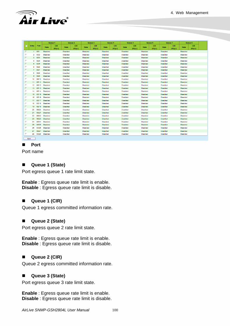
4. Web Management
AirLive SNMP-GSH2804L User Manual 100
Port Port name
Queue 1 (State) Port egress queue 1 rate limit state.
Enable : Egress queue rate limit is enable. Disable : Egress queue rate limit is disable.
Queue 1 (CIR) Queue 1 egress committed information rate.
Queue 2 (State) Port egress queue 2 rate limit state.
Enable : Egress queue rate limit is enable. Disable : Egress queue rate limit is disable.
Queue 2 (CIR) Queue 2 egress committed information rate. Queue 3 (State) Port egress queue 3 rate limit state.
Enable : Egress queue rate limit is enable. Disable : Egress queue rate limit is disable.
4. Web Management
AirLive SNMP-GSH2804L User Manual 101
Queue 3 (CIR) Queue 3 egress committed information rate. Queue 4 (State) Port egress queue 4 rate limit state. Enable : Egress queue rate limit is enable. Disable : Egress queue rate limit is disable. Queue 4 (CIR) Queue 4 egress committed information rate. Queue 5 (State) Port egress queue 5 rate limit state. Enable : Egress queue rate limit is enable. Disable : Egress queue rate limit is disable.
Queue 5 (CIR) Queue 5 egress committed information rate.
Queue 6 (State) Port egress queue 6 rate limit state. Enable : Egress queue rate limit is enable. Disable : Egress queue rate limit is disable.
Queue 6 (CIR) Queue 6 egress committed information rate.
Queue 7 (State) Port egress queue 7 rate limit state. Enable : Egress queue rate limit is enable. Disable : Egress queue rate limit is disable.
Queue 7 (CIR) Queue 7 egress committed information rate.
Queue 8 (State) Port egress queue 8 rate limit state. Enable : Egress queue rate limit is enable. Disable : Egress queue rate limit is disable.
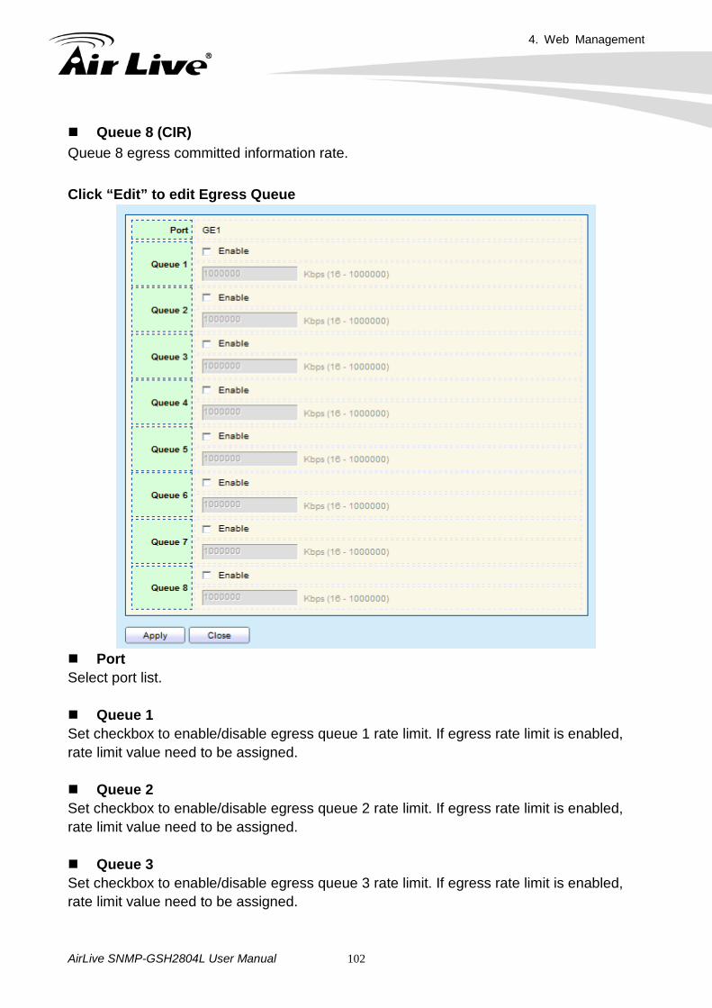
4. Web Management
AirLive SNMP-GSH2804L User Manual 102
Queue 8 (CIR) Queue 8 egress committed information rate. Click “Edit” to edit Egress Queue
Port Select port list.
Queue 1 Set checkbox to enable/disable egress queue 1 rate limit. If egress rate limit is enabled, rate limit value need to be assigned.
Queue 2 Set checkbox to enable/disable egress queue 2 rate limit. If egress rate limit is enabled, rate limit value need to be assigned. Queue 3 Set checkbox to enable/disable egress queue 3 rate limit. If egress rate limit is enabled, rate limit value need to be assigned.
4. Web Management
AirLive SNMP-GSH2804L User Manual 103
Queue 4 Set checkbox to enable/disable egress queue 4 rate limit. If egress rate limit is enabled, rate limit value need to be assigned. Queue 5 Set checkbox to enable/disable egress queue 5 rate limit. If egress rate limit is enabled, rate limit value need to be assigned.
Queue 6 Set checkbox to enable/disable egress queue 6 rate limit. If egress rate limit is enabled, rate limit value need to be assigned.
Queue 7 Set checkbox to enable/disable egress queue 7 rate limit. If egress rate limit is enabled, rate limit value need to be assigned.
Queue 8 Set checkbox to enable/disable egress queue 8 rate limit. If egress rate limit is enabled, rate limit value need to be assigned.
4.14 Diagnostics Use the Diagnostic pages to configure settings for the switch diagnostics feature or operating diagnostic utilities. 4.14.1. Logging 4.14.1.1. Property To display the Logging Service web page.
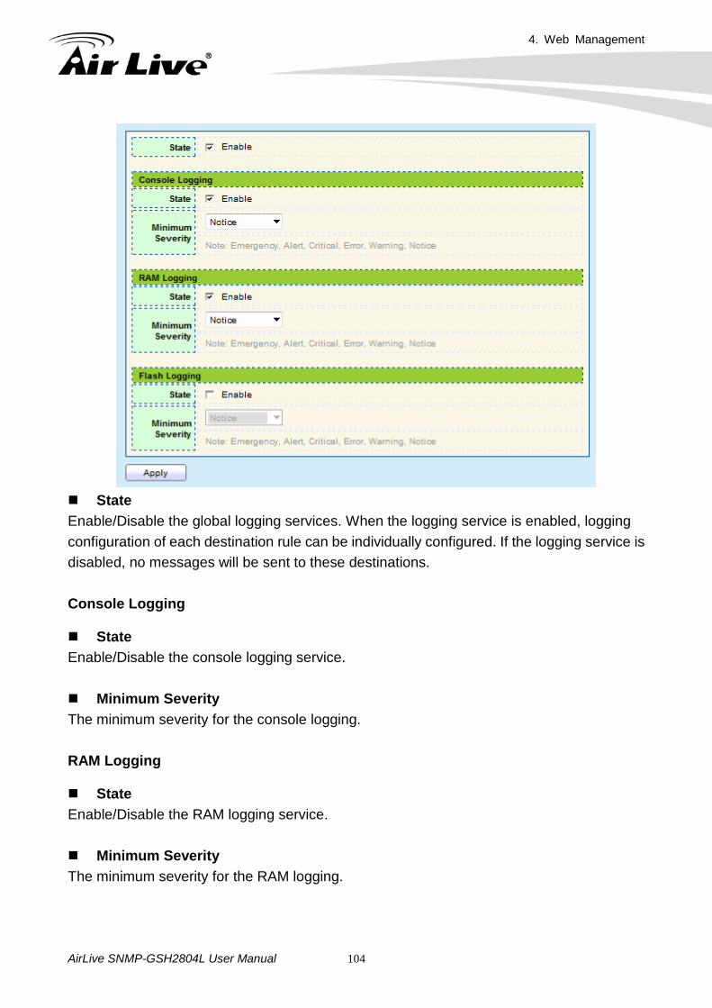
4. Web Management
AirLive SNMP-GSH2804L User Manual 104
State Enable/Disable the global logging services. When the logging service is enabled, logging configuration of each destination rule can be individually configured. If the logging service is disabled, no messages will be sent to these destinations.
Console Logging State Enable/Disable the console logging service. Minimum Severity The minimum severity for the console logging. RAM Logging State Enable/Disable the RAM logging service. Minimum Severity The minimum severity for the RAM logging.
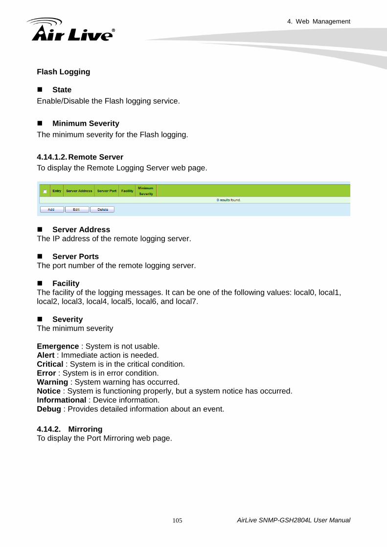
4. Web Management
AirLive SNMP-GSH2804L User Manual 105
Flash Logging State Enable/Disable the Flash logging service. Minimum Severity The minimum severity for the Flash logging. 4.14.1.2. Remote Server To display the Remote Logging Server web page.
Server Address The IP address of the remote logging server. Server Ports The port number of the remote logging server. Facility The facility of the logging messages. It can be one of the following values: local0, local1, local2, local3, local4, local5, local6, and local7. Severity The minimum severity
Emergence : System is not usable. Alert : Immediate action is needed. Critical : System is in the critical condition. Error : System is in error condition. Warning : System warning has occurred. Notice : System is functioning properly, but a system notice has occurred. Informational : Device information. Debug : Provides detailed information about an event. 4.14.2. Mirroring To display the Port Mirroring web page.
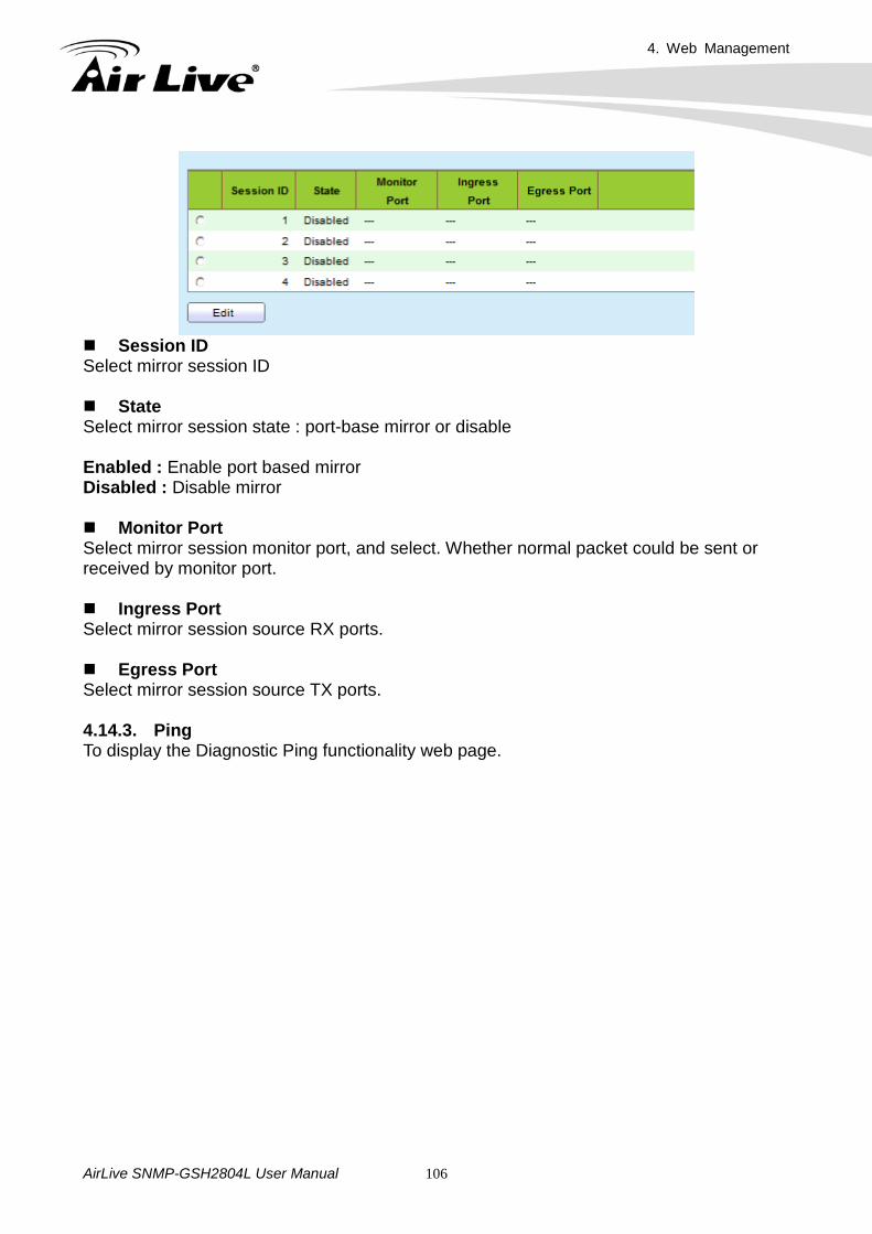
4. Web Management
AirLive SNMP-GSH2804L User Manual 106
Session ID Select mirror session ID State Select mirror session state : port-base mirror or disable Enabled : Enable port based mirror Disabled : Disable mirror Monitor Port Select mirror session monitor port, and select. Whether normal packet could be sent or received by monitor port. Ingress Port Select mirror session source RX ports. Egress Port Select mirror session source TX ports. 4.14.3. Ping To display the Diagnostic Ping functionality web page.
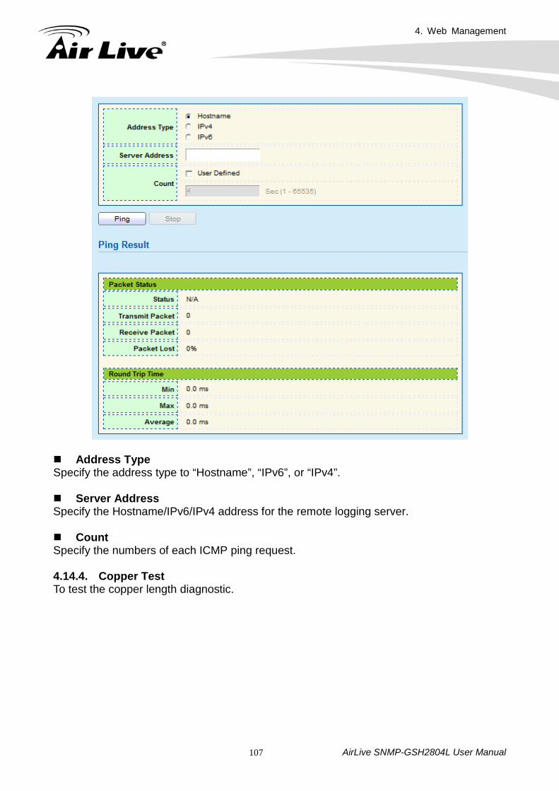
4. Web Management
AirLive SNMP-GSH2804L User Manual 107
Address Type Specify the address type to “Hostname”, “IPv6”, or “IPv4”. Server Address Specify the Hostname/IPv6/IPv4 address for the remote logging server. Count Specify the numbers of each ICMP ping request. 4.14.4. Copper Test To test the copper length diagnostic.
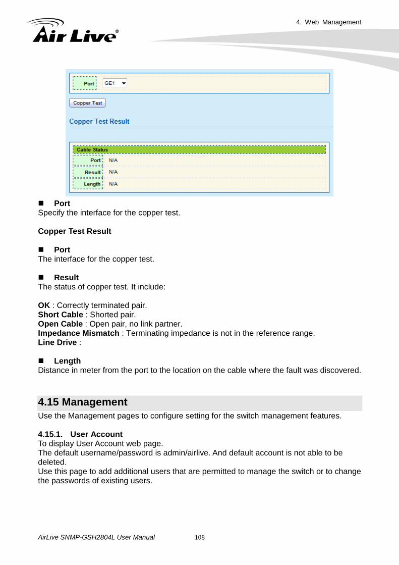
4. Web Management
AirLive SNMP-GSH2804L User Manual 108
Port Specify the interface for the copper test. Copper Test Result Port The interface for the copper test. Result The status of copper test. It include: OK : Correctly terminated pair. Short Cable : Shorted pair. Open Cable : Open pair, no link partner. Impedance Mismatch : Terminating impedance is not in the reference range. Line Drive : Length Distance in meter from the port to the location on the cable where the fault was discovered.
4.15 Management Use the Management pages to configure setting for the switch management features. 4.15.1. User Account To display User Account web page. The default username/password is admin/airlive. And default account is not able to be deleted. Use this page to add additional users that are permitted to manage the switch or to change the passwords of existing users.
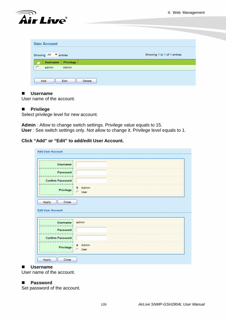
4. Web Management
AirLive SNMP-GSH2804L User Manual 109
Username User name of the account. Privilege Select privilege level for new account. Admin : Allow to change switch settings. Privilege value equals to 15. User : See switch settings only. Not allow to change it. Privilege level equals to 1. Click “Add” or “Edit” to add/edit User Account.
Username User name of the account. Password Set password of the account.
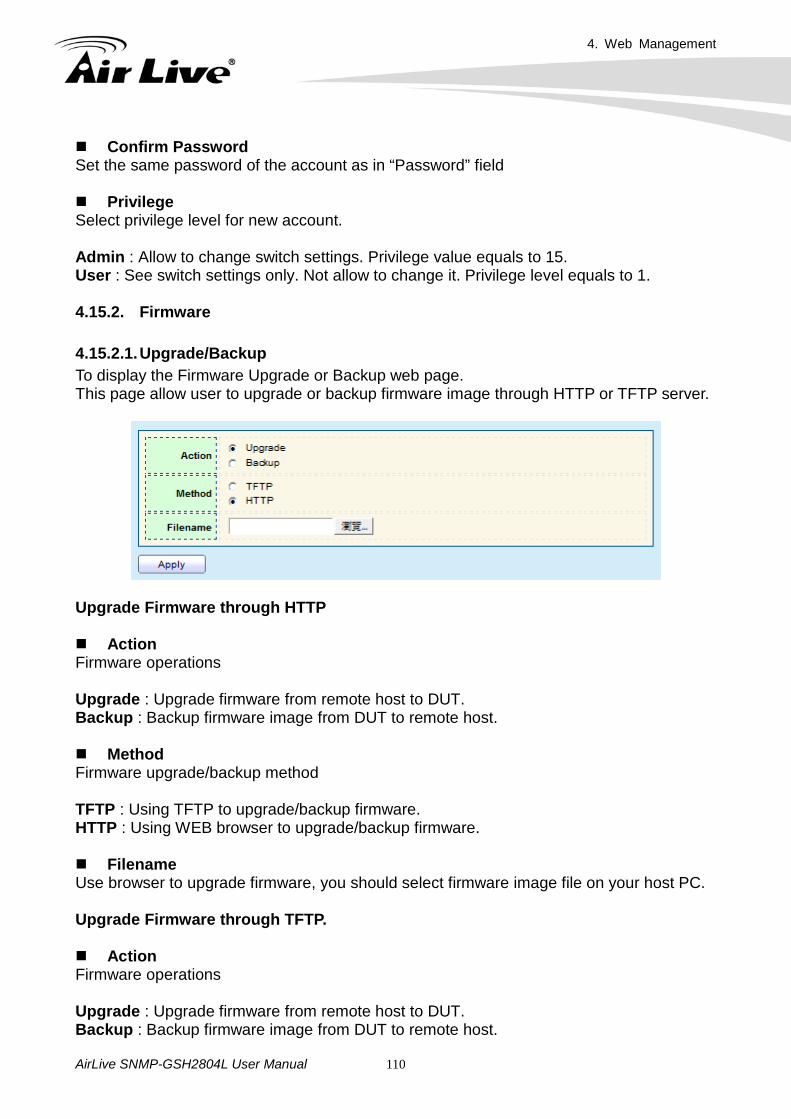
4. Web Management
AirLive SNMP-GSH2804L User Manual 110
Confirm Password Set the same password of the account as in “Password” field Privilege Select privilege level for new account. Admin : Allow to change switch settings. Privilege value equals to 15. User : See switch settings only. Not allow to change it. Privilege level equals to 1. 4.15.2. Firmware 4.15.2.1. Upgrade/Backup To display the Firmware Upgrade or Backup web page. This page allow user to upgrade or backup firmware image through HTTP or TFTP server.
Upgrade Firmware through HTTP Action Firmware operations Upgrade : Upgrade firmware from remote host to DUT. Backup : Backup firmware image from DUT to remote host. Method Firmware upgrade/backup method TFTP : Using TFTP to upgrade/backup firmware. HTTP : Using WEB browser to upgrade/backup firmware. Filename Use browser to upgrade firmware, you should select firmware image file on your host PC. Upgrade Firmware through TFTP. Action Firmware operations Upgrade : Upgrade firmware from remote host to DUT. Backup : Backup firmware image from DUT to remote host.
4. Web Management
AirLive SNMP-GSH2804L User Manual 111
Method Firmware upgrade/backup method TFTP : Using TFTP to upgrade/backup firmware. HTTP : Using WEB browser to upgrade/backup firmware.
Address Type Specify TFTP server address type Hostname : Use domain name as server address. IPv4 : Use IPv4 as server address IPv6 : Use IPv6 as server address. Server Address Specify TFTP server address. Filename Firmware image file name on remote TFTP server Backup Firmware through HTTP Action Firmware operations Upgrade : Upgrade firmware from remote host to DUT. Backup : Backup firmware image from DUT to remote host. Method Firmware upgrade/backup method TFTP : Using TFTP to upgrade/backup firmware. HTTP : Using WEB browser to upgrade/backup firmware. Backup Firmware through TFTP Action Firmware operations Upgrade : Upgrade firmware from remote host to DUT. Backup : Backup firmware image from DUT to remote host.
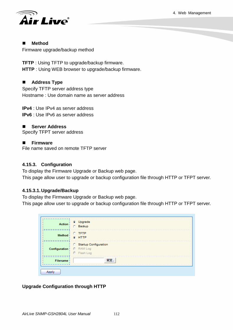
4. Web Management
AirLive SNMP-GSH2804L User Manual 112
Method Firmware upgrade/backup method TFTP : Using TFTP to upgrade/backup firmware. HTTP : Using WEB browser to upgrade/backup firmware. Address Type Specify TFTP server address type Hostname : Use domain name as server address IPv4 : Use IPv4 as server address IPv6 : Use IPv6 as server address Server Address Specify TFPT server address Firmware File name saved on remote TFTP server 4.15.3. Configuration To display the Firmware Upgrade or Backup web page. This page allow user to upgrade or backup configuration file through HTTP or TFPT server. 4.15.3.1. Upgrade/Backup To display the Firmware Upgrade or Backup web page. This page allow user to upgrade or backup configuration file through HTTP or TFPT server.
Upgrade Configuration through HTTP
4. Web Management
AirLive SNMP-GSH2804L User Manual 113
Action Configuration operations Upgrade : Upgrade Configuration from remote host to DUT. Backup : Backup Configuration image from DUT to remote host. Method Configuration upgrade/backup method TFTP : Using TFTP to upgrade/backup Configuration. HTTP : Using WEB browser to upgrade/backup Configuration. Configuration Configuration types Running Configuration : Merge to current running configuration file. Startup Configuration : Replace startup configuration file. Filename Use browser to upgrade Configuration, you should select Configuration image file on your host PC. Upgrade Configuration through TFTP. Action Configuration operations Upgrade : Upgrade Configuration from remote host to DUT. Backup : Backup Configuration image from DUT to remote host. Method Configuration upgrade/backup method TFTP : Using TFTP to upgrade/backup Configuration. HTTP : Using WEB browser to upgrade/backup Configuration. Configuration Configuration types Running Configuration : Merge to current running configuration file. Startup Configuration : Replace startup configuration file.
Address Type Specify TFTP server address type Hostname : Use domain name as server address. IPv4 : Use IPv4 as server address IPv6 : Use IPv6 as server address
4. Web Management
AirLive SNMP-GSH2804L User Manual 114
Server Address Specify TFTP server address. Filename Configuration image file name on remote TFTP server Backup Configuration through HTTP Action Configuration operations Upgrade : Upgrade Configuration from remote host to DUT. Backup : Backup Configuration image from DUT to remote host. Method Configuration upgrade/backup method TFTP : Using TFTP to upgrade/backup Configuration. HTTP : Using WEB browser to upgrade/backup Configuration. Configuration Configuration types Running Configuration : Merge to current running configuration file. Startup Configuration : Replace startup configuration file. RAM Log : Backup log file stored in RAM Flash Log : Backup log files store in Flash. Backup Configuration through TFTP. Action Configuration operations Upgrade : Upgrade Configuration from remote host to DUT. Backup : Backup Configuration image from DUT to remote host.
Method Configuration upgrade/backup method TFTP : Using TFTP to upgrade/backup Configuration. HTTP : Using WEB browser to upgrade/backup Configuration. Configuration Configuration types Running Configuration : Merge to current running configuration file. Startup Configuration : Replace startup configuration file. RAM Log : Backup log file stored in RAM Flash Log : Backup log files store in Flash.
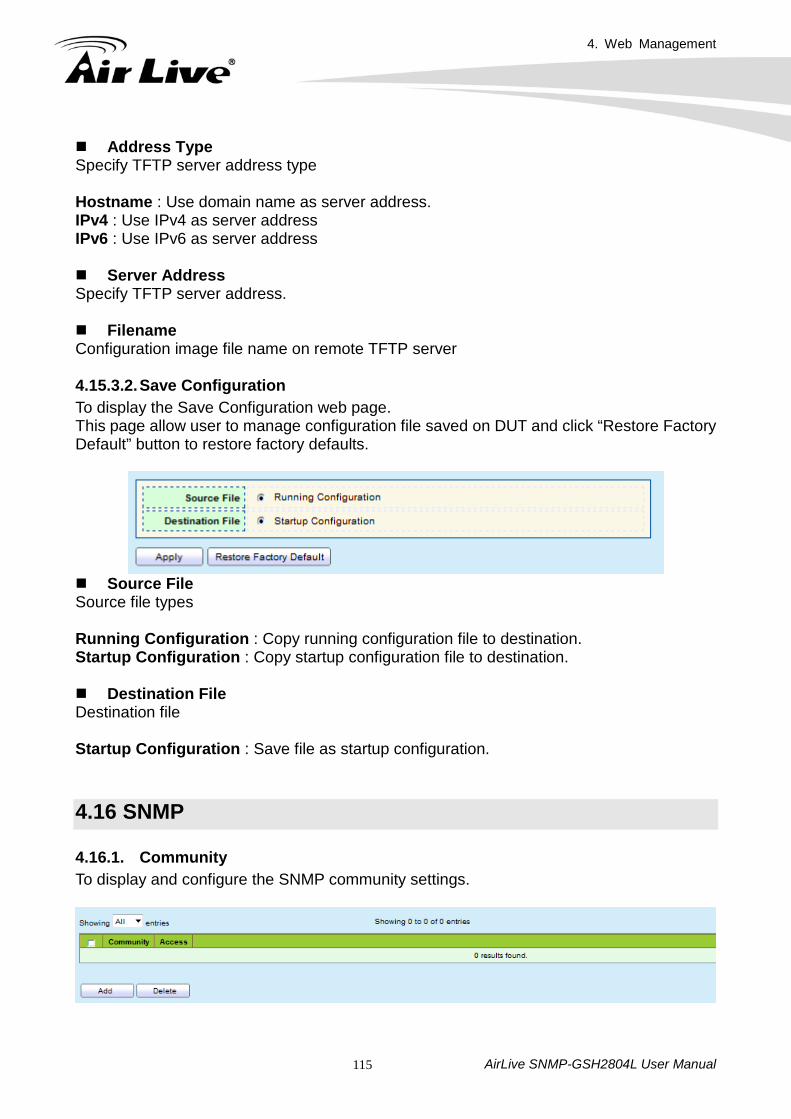
4. Web Management
AirLive SNMP-GSH2804L User Manual 115
Address Type Specify TFTP server address type Hostname : Use domain name as server address. IPv4 : Use IPv4 as server address IPv6 : Use IPv6 as server address Server Address Specify TFTP server address. Filename Configuration image file name on remote TFTP server 4.15.3.2. Save Configuration To display the Save Configuration web page. This page allow user to manage configuration file saved on DUT and click “Restore Factory Default” button to restore factory defaults.
Source File Source file types Running Configuration : Copy running configuration file to destination. Startup Configuration : Copy startup configuration file to destination. Destination File Destination file Startup Configuration : Save file as startup configuration.
4.16 SNMP 4.16.1. Community To display and configure the SNMP community settings.
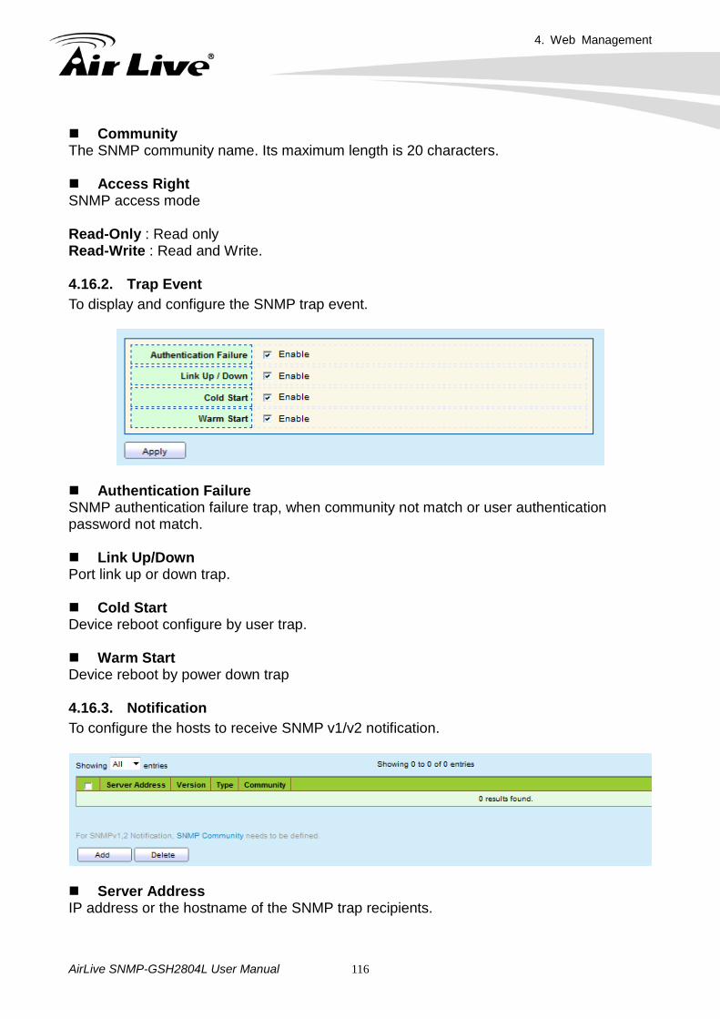
4. Web Management
AirLive SNMP-GSH2804L User Manual 116
Community The SNMP community name. Its maximum length is 20 characters. Access Right SNMP access mode Read-Only : Read only Read-Write : Read and Write.
4.16.2. Trap Event To display and configure the SNMP trap event.
Authentication Failure SNMP authentication failure trap, when community not match or user authentication password not match. Link Up/Down Port link up or down trap. Cold Start Device reboot configure by user trap. Warm Start Device reboot by power down trap 4.16.3. Notification To configure the hosts to receive SNMP v1/v2 notification.
Server Address IP address or the hostname of the SNMP trap recipients.
4. Web Management
AirLive SNMP-GSH2804L User Manual 117
Version Specify SNMP notification version SNMPv1 : SNMP Version 1 notification SNMPv2 : SNMP Version 2 notification.
Type Notification Type Trap: Send SNMP traps to the host. Inform : Send SNMP informs to the host.
Community SNMP community name for notification.
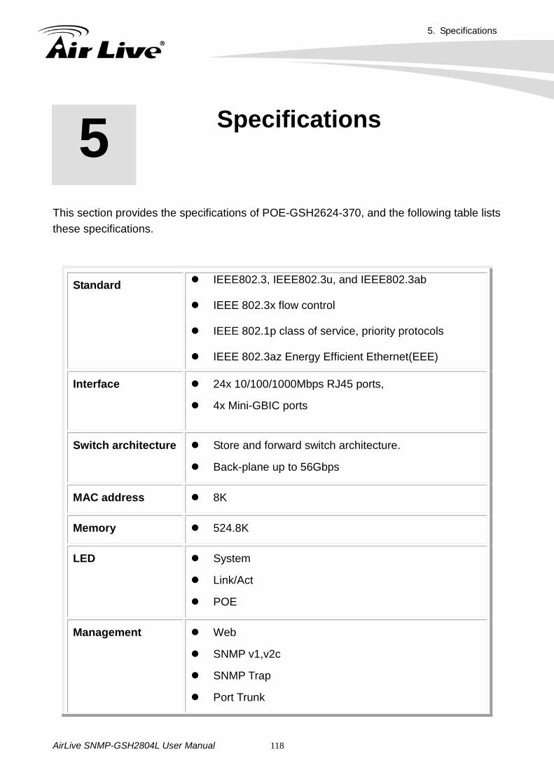
5. Specifications
AirLive SNMP-GSH2804L User Manual 118
This section provides the specifications of POE-GSH2624-370, and the following table lists these specifications.
Standard IEEE802.3, IEEE802.3u, and IEEE802.3ab
IEEE 802.3x flow control IEEE 802.1p class of service, priority protocols
IEEE 802.3az Energy Efficient Ethernet(EEE)
Interface 24x 10/100/1000Mbps RJ45 ports,
4x Mini-GBIC ports
Switch architecture Store and forward switch architecture.
Back-plane up to 56Gbps
MAC address 8K
Memory 524.8K
LED System
Link/Act
POE
Management Web
SNMP v1,v2c
SNMP Trap
Port Trunk
5 5. Specifications
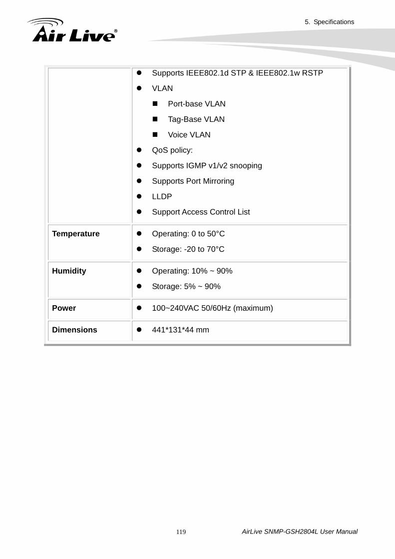
5. Specifications
AirLive SNMP-GSH2804L User Manual 119
Supports IEEE802.1d STP & IEEE802.1w RSTP
VLAN
Port-base VLAN
Tag-Base VLAN
Voice VLAN
QoS policy:
Supports IGMP v1/v2 snooping
Supports Port Mirroring
LLDP
Support Access Control List
Temperature Operating: 0 to 50°C
Storage: -20 to 70°C
Humidity Operating: 10% ~ 90%
Storage: 5% ~ 90%
Power 100~240VAC 50/60Hz (maximum)
Dimensions 441*131*44 mm