Embed Size (px)
Citation preview
AIS 027 : CODE OF PRACTICE FOR USE OF LPGFUEL IN INTERNAL COMBUSTION ENGINE TOPOWER 2 & 3-WHEELED VEHICLES
1. This Code of Practice may be called as “Code of Practice for Use of LPGFuel in Internal Combustion Engine to Power 2 & 3-Wheeled Vehicles”.
2. SCOPE
This Code of Practice shall apply to design, construction, installation,operation, maintenance, inspection, testing and fueling of liquefiedpetroleum gas (LPG) system for motor vehicles, in which LPG is usedeither wholly or as bi-fuel for the internal combustion engine of 2 & 3-wheeled vehicles. In general the Standard is directed towards vehicleinstallations.
3. This Code of Practice does not cover the areas where major structuralmodifications (major structural modifications are those not defined inclause no. 4) are to be carried out in the vehicles. Before commencementof major structural modifications, guidelines from the vehiclemanufacturers shall be sought for.
4. Any alteration or modification to any motor vehicle to install equipmentfor LPG system shall be carried out in accordance with sound engineeringpractices and in compliance with Central Motor Vehicles Act 1988 andCentral Motor Vehicles Rule, 1989 and their superseding amendment andnotification issued thereafter. The following aspects shall be taken intoconsideration during alteration or modification:
Where the modifications are made to:
a) Suspension: mounting locations, geometry, ground clearanceadjustment, axles and sub-axles or steering mechanism.
b) Original fuel storage: the fuel tank assembly, fuel tank mounting,venting or filler assemblies
c) Vehicle structures: Holes greater than 13 mm shall, not located within40 mm from the edge of panel, welded joint or direct load bearingpoint (such as belt anchor). The only holes permitted greater than 13mm diameter are for the installation of the filling valve or for ventingpurposes.
d) Braking system including the hand brake and components.In this aspect design guidelines supplied by vehicle manufacturers, vehiclesafety standards of Indian or relevant standards, wherever applicable shall bereferred.
Only equipment and systems approved by the relevant Statutory Authority /Test Agency shall be used.
5 DEFINITIONS
For the purpose of this Standard, the following definition shall apply:
a) APPROVAL OR APPROVED: means Approval or Approved byStatutory Authority.
b) AUTHORISED PERSON: A person, normally an automotiveworkshop person, authorised by the vehicle manufacturer or theconversion kit manufacturer/kit supplier, specially trained forinstallation, maintenance and periodic inspection of motor vehicleconverted for bi-fuel or dedicated operation of internal combustionengined 2 & 3-wheeled vehicles.
c) AUTOMATIC FILL LIMITER: means a provision in the fillingsystem of the Auto LPG Tank, which automatically terminates fillingwhen the predetermined liquid level in the Auto LPG Tank has beenreached.
d) AUTOMATIC FUEL SHUT-OFF VALVE: means a device such assolenoid valve for shutting off the supply unless certain essentialconditions exist.
e) AUTO LPG TANK (ALT): means cylinder/container/tank meant forcontaining LPG to be used as fuel for the 2 & 3-wheeled vehicleengine and approved/endorsed by Chief Controller of Explosivesunder Gas Cylinders Rules, 1981 and meeting the requirements as perIS: 14899 (as amended from time to time).
f) CONTENTS GAUGE: means a gauge which gives a visual indicationof the level or quantity of the LPG contained in Auto LPG Tank.
g) CONVERSION KIT: means a complete system assembly from autoLPG tank to gas-air mixer for converting vehicle to run on LPG.The kit needs to be duly tested and approved by one of TestingAgencies mentioned in Central Motor Vehicles Rules 126 in bi-fuelmode of LPG/gasoline or dedicated mode of LPG.
h) EXCESS FLOW CHECK VALVE: means a valve normally in theopen position which closes automatically in the direction of flow forwhich it is designed, when a predetermined flow limit is exceed asdetermined by the pressure drop.
i) FLOW-RATING PRESSURE: means the pressure at which the reliefvalve is rated for flow.
j) GAS AIR MIXER: means a device for introducing gaseous fuel to theinduction air of the engine.
k) GAS CYLINDER RULES, 1981: means The Gas Cylinder Rules,1981 (with latest amendments) framed under Indian Explosive Act,1884 and administered by Chief Controller of Explosives.
l) LIQUEFIED PETROLEUM GAS FOR AUTOMOTIVE PURPOSES,hereinafter referred to as Auto LPG: means a mixture of certain lighthydrocarbons derived from petroleum which are gaseous at normal
ambient temperature and atmospheric pressure but may be condensedto the liquid state at normal ambient temperature by the application ofmoderate pressure meeting the requirements of Indian StandardSpecifications IS:14861 (as amended from time to time).
m) MULTI-FUNCTION VALVE: means an assembly for mounting anauto LPG tank for filling and withdrawal of LPG along with safetydevices including:
i. Automatic fill limiterii. Service valveiii. Excess flow check valveiv. Pressure relief devicev. Fusible Plugvi. Content Gaugevii. Inlet connected to fill connector having Non-Return Valve
Multi function valve assembly shall conform to latest Indian Standard(amended from time to time) and approved/endorsed by Departmentof Explosives (DOE).
n) NON-RETURN VALVE: means a valve, which permits fuel to flow inone direction only.
o) PRESSURE : Refers to gauge pressure.
p) RELIEF VALVE: means an automatic pressure relieving device,communicating directly with the vapour space of the tank and actuatedby the static pressure upstream of the valve which opens in proportionto the increases in pressure over the opening pressure to maintaininternal fluid pressure. This also includes a device dischargingexcessive pressure due to temperature rise between two valves /isolated sections.
q) SERVICE VALVE: means a manually operated or remotely controlledshut-off valve fitted on the Auto LPG Tank which can open or shut offthe LPG supply.
r) VAPOURISER/REGULATOR: means a device which vapourisesliquid LPG and reduces fuel pressure at a level appropriate for deliveryto the gas-air mixer in case of liquid/vapour withdrawal system.
6. PROTOTYPE OF CONVERSION KIT / OE FITMENT TO BESUBJECTED TO TEST:
i. Every conversion kit manufacturer / supplier shall submit theconversion kit to be manufactured by him for test by Vehicle Research& Development Establishment of the Ministry of Defence, Govt. ofIndia or Automotive Research Association of India, Pune or IndianInstitute of Petroleum, Dehradun and such other agencies as may bespecified by the Central Govt. for granting a certificate by that agencyas to the compliance of provisions of the Motor Vehicle Act, Rulesmade thereunder and these Codes.
ii. An application for approval of conversion kit shall contain the followinginformation :
a. The identity of the manufacturer and the country of origin ofthe component;
b. The specification to which the component is to bemanufactured and
c. The quality control procedures to be adopted during the courseof construction of the component.
iii. If any type approval is issued it will be made subject to the conditionthat the conversion kit is installed and operated in accordance with therequirements of such approval. The Ministry of Road Transport andHighways may impose other conditions of type approval as deemappropriate, depending on its anticipated use. However, if any problemarises with the kit or components thereof, at the discretion of testingagency concerned / MORTH, kit may be subjected to fresh typeapproval.
i. The type approval of a conversion kit may be revoked or the conditionsof approval may be varied by the Ministry of Road Transport andHighways if the kit or any component thereof is found to be unsafe inservice or if the circumstances of use of the conversion kit or anycomponent thereof alter those originally envisaged.
7. AUTO LPG TANK FITTINGS/MARKINGS
I. Fittings- All auto LPG tanks permanently attached to the vehiclesshall have fitting as per IS:14899 (as amended from time to time).
(A) PRESSURE RELIEF VALVE
i. The pressure relief valve shall be set at a pressure of110% of the design pressure of auto LPG tank and haveadequate relieving capacity to prevent internal pressurerising about 120% of design pressure under fire condition.
ii. The relief valve shall communicate directly with thevapours space of the ALT with no valve in between andshall be fitted internally, only the relieving outlet beingoutside.
iii. The discharge from the relief valve shall not be directedinto the passenger space of the vehicle.
iv. Manufacturer’s symbol/name, set pressure, dischargecapacity and serial number shall be marked on the valve.
(B) FILLING CONNECTION/AUTOMATIC FILL LIMITER
(i) Size of filling receptacle shall conform to the ECERegulation No. 67 or equivalent standard adopted byDOE. However, the vehicle manufacturer/kit installer
may seek the guidance from the Ministry of Petroleumand Natural Gas and DOE.
(ii) The automatic fill limiter working on a float mechanismshall cut-off the liquid inlet when the predeterminedmax. level of 80% water capacity of ALT is reached.
(iii) The filling connection shall be provided with a filler capwhich shall be captive to the connection and shall beeither capable of withstanding the design pressure of theALT or designed so that pressure does not accumulate.If the cap is the pressure related type, the connectionshall be designed so as to relieve the accumulatedpressure commencing at the backing off of not morethan one turn of the cap.
(C) SERVICE VALVE
Either a manually operated or remotely controlled servicevalve, which can open or close the auto LPG supply to thevaporizer, pressure regulator during maintenance / servicing,etc., shall be fitted downstream of excess flow check valve.
(D) EXCESS FLOW CHECK VALVE
A valve normally in open position, closes automatically inthe direction of flow for which it is designed.
(E) CONTENT GAUGE
The content gauge of dial type shall be fitted to the AutoLPG Tank for indicating the level/quantity of LPG in thefuel tank, the dial to be placed into the dash board/handlebar of the vehicle. In addition, if required, a fixed liquidlevel gauge may be provided in the tank.
II. MARKINGS – The Auto LPG Tank shall have the markings as perIS:14899, as amended from time to time.
8. The fitment of auto LPG tank and other kit components in the motorvehicle shall be carried out as per following clauses:
(A) LOCATION AND VENTILATION OF AUTO LPG TANK
i. Auto LPG Tank, fittings, and pipe work shall be mounted in aprotected location inside the perimeter of the vehicle. Thetank shall not be so located that the vehicle drivingcharacteristics are adversely affected.
ii. For externally mounted tanks in no case shall the tank valvesbe positioned less than 100 mm from the front and rear endsfor 2-wheeler and 200 mm from the extremities of the vehiclefor 3-wheeler unless they are protected to minimise thepossibility of damage due to collusion, overturning or otheraccident.
iii. In case of 3-wheeler, the Auto LPG Tank shall be situatedand vented so that any gas escaping due to leakage from tankfittings shall not enter the vehicle passenger compartment ordriver space.
iv. The Auto LPG Tank shall not be fitted:
1) On the roof or above any passenger compartment(applicable for 3-wheeler only).
2) In a position behind the driver seat (seat adjusted torearmost position), which will hinder the driver seatadjustment unless specifically approved by the testingagency.
3) In a position beneath the vehicle that decreases theeffective ground clearance.
Note: The attachment of the auto LPG tank to theroof of the vehicle, and particularly to the gutters, isgenerally considered to be of inadequate strength, andunsatisfactory for a number of other reasons. Suchinstallations require specific approval, which is usuallygiven only for special vehicles, and takes into accountsuch aspects as vehicle speed, cylinder protection andstrength of mountings.
i. Cylinder shall be secured firmly to the body of vehicle toprevent it from working loose when vehicle runs on a roughterrain or accidentally overturns or falls down to prevent itfrom being thrown not as projectile in the event of an impact.
(B) Auto LPG Tank location ground clearance
Auto LPG Tank shall be located in accordance with the followingrequirements:
i. The vehicle mass for determining ground clearance shall bethe laden mass, including permanent non-standardattachments to the vehicle with all fuel, water and oilcontainer full.
ii. The tank installed between and behind axles shall not belower than the lowest of the following points and surfacesforward of the tank.
1) The lowest structural component of the body.
2) The lowest structural component of the frame or sub-frame, if any.
3) The lowest point of the engine.
4) The lowest point of the transmission (including theclutch housing or torque converter housing asapplicable) but excluding differential housings.
iii. All clearances shall be measured to the bottom of the AutoLPG Tank, or to the lowest fitting support or attachment onthe Auto LPG Tank housing whichever is the lowest.
(C) Internal Auto LPG Tank: Where an Auto LPG Tank is locatedwithin the body shell of a vehicle, either
i. The whole body of the Auto LPG Tank together with itsattached components and fittings shall be enclosed in acompartment; or
ii. The valves, fittings and pipe connections associated with orattached to the Auto LPG Tank shall be enclosed in a localisedsub-compartment, which is attached to the Auto LPG Tank andvented to the atmosphere.
Provision shall be made for ready access to the service valve in allinstallation arrangements.
(D) Construction of compartments and sub-compartments:
An Auto LPG Tank compartment or sub-compartment shallcomply with the following requirements:
i. Construction shall be such that any gas which might leak fromany fittings, component or piping, can not pass to any otherenclosed compartment, passenger space or luggage space of thevehicle.
ii. When a compartment or sub-compartment has been subjectedto a hydrostatic internal pressure of 30 kpa for a period of 5minutes, sealing materials or gaskets shall not be displaced orotherwise lose integrity.
iii. Hatches, covers, or construction joints which may need to beopened or dismantled during maintenance or inspection shall becapable of being opened at least 10 times without adverseeffects on durability. Hinges and locking devices of hatchesand covers shall be designed to prevent the dislodgment of thehatch or cover when in the closed and locked position.
iv. The construction shall be such that if subjected to a pushingforce of 60 kgf applied at any point on any external face of thesub-compartment any resultant damage shall not be of a natureto permit gas leakage in the event of pressure testing as in (ii)above. The pushing force shall be applied by a measuringinstrument having a flat circular face of 20 mm diameter.
v. A compartment or sub-compartment shall not contain anignition source or electrical equipment or wiring unless it isintrinsically safe.
NOTE – Items (ii), (iii) and (iv) are intended to be the basis of approval forproof of design.
(E) Ventilation: One or more vents to the outside of the vehicle shall beprovided, the aggregate area of which is not less than 250 mm2 andwhich can not be blocked. The vents shall be so located as to drainany vapour, which may accumulate in the bottom of thecompartment or sub-compartment, and shall exit not less than 250mm from an exhaust pipe or other heat source. (Ref also F (iii)below). Holes for venting shall be positioned not less than 40 mmfrom the edge of a panel or welded joint or direct load bearingpoint.
(F) Ducting: All piping or hoses that pass through an enclosed area ofthe vehicle shall be within conduit gas-tight from the vehicleinterior, vented unobstructed to outside atmosphere and protectedfrom external damage and shall comply with the followingrequirements:
i. The ducting shall be as short as practicable.
ii. All connections shall be mechanically clamped and shallnot depend on adhesives or sealing compounds to retainthem in place. Protection in the form of a gasket shall beprovided to prevent damage to the conduit by the clampingdevice.
NOTE: To ensure a gas tight seal between the vent andducting material, it may be necessary to use a suitablesealant or gasket when connecting the ducting to the vent.
iii. The material of the conduit used for ducting shall besufficiently strong to resist mechanical damage, preserveventing integrity, protect the piping or hose within it, shallnot support combustion and shall meet the followingminimum criteria:
(a) The conduit shall withstand an internal test pressureof 30 kpa.
(b) The conduit shall not suffer sufficient damage topermit leakage when tested by applying 60 kgf staticforce applied through 20 mm diameter, in thefollowing manner:
1) Applied to a free end of conduit (minimum lengthof 500 mm).
2) With the conduit connection clamped up inposition the force then applied 5 mm from theend of this coupling so as to place the connectionin tension.
3) Flammability: The material shall conform to SAEJ369a class SE/NBR.
4) Presence of resistance to ultraviolet degradationagent shall be confirmed.
NOTE – Item (iii) shall be the basis of approval for proof of designof the conduit.
(G) Auto LPG Tank (s) installation
Attachment to vehicle: Auto LPG Tank(s) shall be securelyattached to the vehicle to prevent slipping, rotating and jarringloose, in accordance with the following requirements:
i. The method of attachment shall not cause undue stresses orwear in the Auto LPG Tank shell.
ii. Fixing lugs, brackets and the like if welded to the Auto LPGTank shall be attached during manufacture and specificallyshall not be attached by field welding or brazing.
iii. The mounting method shall not significantly weaken thevehicle structure, and reinforcement shall be added wherenecessary to ensure compliance with (iv) below. An air gap ofnot less than 5 mm shall be provided between the Auto LPGTank and vehicle structure.
iv. The force necessary to separate the Auto LPG Tank from thevehicle shall not be less than 20 times the mass of the full AutoLPG Tank applied in any direction on external surface of AutoLPG tank.
The strength of the anchorages may be established by static test(forces directed through the centre of mass of the Auto LPGTank).
v. In the absence of testing or where calculations areimpracticable, the following requirements shall apply:
a) There shall be at least 4 points of attachment to the vehiclestructure. The spacing between these shall be sufficient toensure the stability of the Auto LPG Tank.
b) Where a Auto LPG Tank is anchored to sheet metal, thesheet metal shall be reinforced by a plate of not less than3600 mm2 and a thickness of not less than 2.5 mm orappropriate thickness supported by calculations or testreport. It is preferred that round washer be used but wherea square plate is fitted the corners shall be radiused. Anysuch reinforcement plate/washer shall be contoured to theshape of the sheet metal or chassis rail.
c) Where anchorage bolts pass through a hollow section,provision shall be made to prevent collapse of that sectionunder load.
d) Anchorage bolts or studs shall have diameter not less thanthat shown in table 1 and shall conform to property class8.8 as per IS 1364 or equivalent ISO 4014 with nuts to IS1364 or ISO 4032.
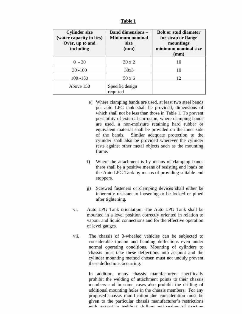
Table 1
Cylinder size(water capacity in ltrs)
Over, up to andincluding
Band dimensions –Minimum nominal
size(mm)
Bolt or stud diameterfor strap or flange
mountingsminimum nominal size
(mm)
0 - 30 30 x 2 10
30 -100 30x3 10
100 -150 50 x 6 12
Above 150 Specific designrequired
e) Where clamping bands are used, at least two steel bandsper auto LPG tank shall be provided, dimensions ofwhich shall not be less than those in Table 1. To preventpossibility of external corrosion, where clamping bandsare used, a non-moisture retaining hard rubber orequivalent material shall be provided on the inner sideof the bands. Similar adequate protection to thecylinder shall also be provided wherever the cylinderrests against other metal objects such as the mountingframe.
f) Where the attachment is by means of clamping bandsthere shall be a positive means of resisting end loads onthe Auto LPG Tank by means of providing suitable endstoppers.
g) Screwed fasteners or clamping devices shall either beinherently resistant to loosening or be locked or pinedafter tightening.
vi. Auto LPG Tank orientation: The Auto LPG Tank shall bemounted in a level position correctly oriented in relation tovapour and liquid connections and for the effective operationof level gauges.
vii. The chassis of 3-wheeled vehicles can be subjected toconsiderable torsion and bending deflections even undernormal operating conditions. Mounting of cylinders tochassis must take these deflections into account and thecylinder mounting method chosen must not unduly preventthese deflections occurring.
In addition, many chassis manufacturers specificallyprohibit the welding of attachment points to their chassismembers and in some cases also prohibit the drilling ofadditional mounting holes in the chassis members. For anyproposed chassis modification due consideration must begiven to the particular chassis manufacturer’s restrictionswith respect to welding, drilling and sealing of existing
holes. Advice on these matters can be obtained from thechassis manufacturer.
viii. More than one Auto LPG Tank
Specific design may be required for mounting.
ix. The Auto LPG Tank data plate shall be easily read when inthe installed position.
x. Heating: Heating shall not be applied to fuel Auto LPGTanks for purposes of increasing the internal pressure or thesupply of fuel.
xi. Heat Shielding: Auto LPG Tank shall be situated as farfrom the exhaust system as practicable and in no case shallthe distance be less than 75 mm. If the clearance betweenAuto LPG Tank and exhaust system is less than 100 mmshielding against radiation shall be provided. Wherepractical the shielding shall be positioned halfway betweenthe exhaust and Auto LPG Tank but in any case the air gapshall not be less than 15 mm.
NOTE: Exhaust systems shall not be positioned below theAuto LPG Tank unless there is no practicalalternative route.
xii. Shielding: Valves and connections on Auto LPG Tank shallbe protected to minimize the possibility of damage due toaccidental contact with stationary objects or from looseobjects thrown up from the road. Valves shall be protectedto minimize the possibility of damage due to collision,overturning, or other accident. Parts of the vehicle may beused to provide such protection to valves and fittings.
9. LPG Fuel Line Pressure Exceeding 4.5 kg/cm2 (g)
LPG fuel line for pressure exceeding 4.5 kg/cm2 (g) used in the liquid orvapour phase high pressure piping shall be either
a) steel, copper or copper alloy (9(i))
b) Flexible (9(ii)(a))
i. Rigid piping : High pressure piping of steel , copper or copperalloy shall be suitable for use with Auto LPG. The pipeline shallbe designed for a minimum pressure of 32 kg /cm2 (g) with a factorof safety of 4 and shall be tested at a pressure of not less than 48kg/cm2 (g).
ii. Fuel line size: Piping for liquid/vapour LPG shall be as small aspossible consistent with the needs to supply the maximumrequirements of the engine and to permit the excess flow valve tofunction in the event of rupture or disconnection.
(a) Flexible hose: Flexible high pressure hose shall be suitablyfiber braided hose conforming to IS: 9573 with latestamendment, except testing on slab (the bursting pressureshall be tested for five times of working pressureencountered in service).
iii. Inspection: At the time of periodic inspection the hose shall beinspected for twists, kinks and damage or abrasions to the coverwhich expose the wire. The hose shall be condemned on detectionof any one of these defects. At no time shall flexible hose beplaced back into service after removal from the vehicle.
iv. Joints and connections:
a) Every joint or connective fitting in rigid high-pressure fuelline shall be tested for 48 kg/cm2 without leakage orfailure.
b) The number of joints and connections shall be the minimumfor the inclusion of all components.
c) Joints or connections in LPG fuel lines shall be inaccessible positions for easy inspection.
d) Connection means shall provide positive retention of thefuel line in the fitting (e.g. by double inverted flaring of thetube end).
v. Securing and location:
High pressure piping and hoses in vehicles shall comply with thefollowing:
a) No LPG fuel line inside the part of any vehicle occupied bythe driver or passengers shall be outside the sealed andvented enclosure, (except as provided for in clause 8(F).
b) All LPG fuel lines shall be positioned for protection fromthe possibility of damage by impact, accident or looseobjects thrown by the vehicle wheels/tyres. Parts of thevehicle may be used to provide such protections.
c) LPG fuel lines shall not be located inside box sections or inother inaccessible locations nor shall they be installed inany location which is not adequately protected from sourcesof heat, abrasion or from impact.
d) Use of the drive shaft tunnel for fuel line location is notdesirable or recommended. If such routing is the onlypossible practicable method of installation, the fuel linemust be positioned along the lower corner of the tunnelwith the underside of the fuel line not more than 15 mmabove the intersection with the floor plan. The fuel lineshould follow this route for the shortest distance possible.The fuel line shall have a minimum clearance of 40 mm
with the drive shaft under all operating conditions. Thismethod is not applicable to vehicles where the open axleshaft passes through a tunnel.
e) Use of the wheel arch for fuel line location is not desirableor recommended.
f) Fuel lines shall follow the shortest practical route takinginto account the requirements of clause 10 (B) (ii).
g) Fuel lines shall be effectively secured to the chassis frameor vehicle body by clips spaced not more than 300 mmapart in case of 2-wheeler and 500 mm in case of 3-wheeler. In order to prevent the possibility of frettingcorrosion or erosion of the fuel line cushioning must beprovided to protect the pipe from the chassis/body and theclips themselves. Suitable grommets must be providedwhere the pipe passes through any body panel.
h) Manifolds used in multi Auto LPG Tank applications shallbe installed in a protected location. Manifold branchpipelines shall be sufficiently flexible to prevent damage tothe lines, valves and fittings due to vibration, expansion orcontraction.
i) LPG fuel line subjected to Auto LPG Tank pressure shall beprotected from heat radiated from any exhaust componentwithin 150 mm of it by a radiation shield. In the event ofclearance being less than 100 mm the shielding shall consistof 2 mm thickness of sheet metal separated from each otherby an air gap of 15 mm and positioned halfway between theexhaust and fuel line. In no case shall the clearance be lessthan 75 mm.
j) Fuel lines shall not be installed where any part will bepermanently hidden from sight or can not be inspected oreasily replaced (except as provided for in clause 8(F)).
10. LPG fuel line pressure not exceeding 4.5 kg/cm2 (g)
(A) All LPG fuel line for use at service pressure not exceeding4.5 kg/cm2 (g) .
i. Such a low pressure fuel line shall be of flexible materialcomplying with IS:9573 as amended, except testing onslab (the bursting pressure shall be tested for five timesof working pressure encountered in service or it shall betested for 10 bar whichever is higher). Such low pressurefuel line shall be capable of sustaining 5 times themaximum pressure likely to be encountered in service andshall comply with clause 9 (v) ((a) to (f) and (j)).
ii. Joints and connections for low pressure fuel lines shall besuitable for use with LPG and capable of sustaining 5 timesthe maximum pressure likely to be encountered in serviceand shall comply with clause 9 (iv) (b and c).
(B) Flexibility
i. Low pressure hose shall be of sufficient length and flexibleto accommodate engine movement.
ii. High pressure fuel line shall be installed so as toaccommodate any relative movement between chassis/bodyand fuel system components or temperature variations inthe fuel line.
iii. All runs or rigid fuel line piping between any twocomponents shall be installed with a ‘pigtail’ or U bend toprovide this essential flexibility (Ref. 10(B) (ii).
11. LPG CONTROL EQUIPMENT:
The LPG fuel control equipment includes all the equipment necessary to convertLPG at high pressure at the cylinder to LPG air mixer for supply to the engine.
The control equipment shall consist of following namely
a. Filter: At the termination of every LPG service fuel lineimmediately before entry to the LPG shut off valve shall be fitted aproperly designed filter capable of removing all particulate matterfrom the fuel that could cause malfunction of shut-off valve orpressure regulator.
b. Automatic fuel shut-off device: This device shall be fitted betweenthe filter and the inlet of the vaporizer / regulator. The device shallautomatically act to prevent the flow of liquid into the vaporizer incase of liquid withdrawal or regulator in case of vapour withdrawalunless both the following conditions are satisfied.
(i) The ignition is on(ii) The engine is turning
c. Vaporizer and regulator or regulator system: The system shall notpermit gas to pass after the engine has stopped turning, irrespectiveof whether the ignition is on or off. This system shall be installedso that:
i. It is securely mounted as far as practical from theextremities of the vehicle.
ii. It is mounted securely and as close to the engine carburettorposition as convenient.
iii. It is easily accessible for routine maintenance, adjustmentand inspection.
It is situated as far from the exhaust system as practical.Where this distance is less than 150 mm it shall be shieldedfrom radiant heat and any impingement from exhaust gasesdue to exhaust system failure.
iv. It is reasonably protected from impact in a collision.
v. It is adjacent to or connects directly with the LPG shut-offvalve, any fuel line connection to which shall be kept asshort as possible.
For liquid withdrawal system: The water circulating system(Where required) is connected in accordance with themanufacturer’s instructions, and no flow control valve in thesystem can shut-off original equipment water flow.
Where possible, the vaporizer should not be at a level higherthan the top of the radiator, as insufficient water may causefreezing.(refer Appendix E)
vi. It allows sufficient free movement of all hoses.
d. The regulator assembly shall not be attached to the engine assemblyunless otherwise specified by the manufacturer and then shall befitted only in accordance with the manufacturer’s recommendedinstructions.
e. Backfire Deflector: Immediately prior to the mixer, a backfiredeflector to arrest flash back, shall be installed in the air intake,which shall meet the requirements of Appendix F of this Standard.
Vehicle manufacturer/kit manufacturer/kit supplier shall submit thetest report or certificate complying with the requirementsmentioned in Appendix F of this standard. It is not necessary tocarry out the test if declaration is submitted.
f. The mixer shall be securely mounted and when remotely fittedshall be suitably bracketed to support its own weight and appliedworking forces.
g. There shall be no air filter element fitted downstream of the gas airmixer.
h. Bi-fuel/Dedicated fuel system:
(i) Bi-fuel type: A bi-fuel system is defined as a systemequipped to operate with either on LPG or some other fuele.g. petrol.
(ii) Dedicated fuel type: A dedicated fuel system is defined asthe system equipped to operate wholly on LPG.
i. For bi-fuel type:
(a) A shut-off device shall be installed in the bi-fuel system.This device shall shut-off the optional fuel supply to theengine when this fuel is not required.
(b) If the shut-off device is in the form of a solenoid operatedshut-off valve, it must be fitted between the fuel pump andthe carburettor. The valve shall be mounted securely so
that its weight is not taken on any part of the carburettor orfuel lines.
(c) Where the shut-off device is mounted remotely from theengine, flexible hose of sufficient length shall be used toaccommodate engine movement. In all cases the deviceshall be mounted in a position reasonably protected fromdamage in a collision and shall be as far as practicable fromhigh tension electrical equipment.
(d) Where flexible hose is used as part of the installation, thehose shall be a reinforced hose for the LPG fuel (as perclause 9 (ii)(a)).
j. Bypass relief device (if applicable): A bypass relief device shall beinstalled in the fuel pump or between the fuel pump and theautomatic shut-off valve in the liquid fuel line to the carburettor onvehicles equipped with bi-fuel systems for the use of gasoline andgaseous fuel. The relief device need not be installed on fuel pumpscontaining a bypass relief device as original equipment.
k. Fuel selection control: A fuel selection control shall be providedwhich shall have at least three positions, clearly marked for theselection of each of the two fuels. The selection control shall beplaced within easy reach of the driver or operator. For vehiclesfitted with electronic fuel injection a two position switch isacceptable.
l. Installation: The LPG control equipment shall be:
i. Installed in positions that are accessible for routineinspection, maintenance and adjustment.
ii. Mounted securely and reasonably protected from damage ina collision.
iii. Remote from the vehicle engine exhaust system orprotected therefrom by a metal shield.
iv. No closer than is avoidable and practicable to any electricalequipment capable of sparking.
12. ELECTRICAL WIRING
a. All wiring shall be proper installed, taped clipped or contained in aloom along its length.
b. Wiring cables shall comply with the requirements of JIS C 3406 orequivalent standard, for only conductor resistance test; sparkand immersion test to withstand voltage.
The kit supplier/manufacturer or vehicle manufacturer shall submitthe test certificate/test report complying with above requirements.
c. The electrical circuit shall be provided with a current limitingdevice. This equipment or fuse shall be dedicated to the LPG fuelsystem.
NOTE: Where fuses are used they should be sized to conform suchthat 110% of rated current of the circuit-shall not fuse within 60minutes and at 135% of the rated current of the circuit, it shallfuse within 60 seconds.
A circuit breaker meeting these requirements is acceptable.
d. Connectors and terminals shall be insulated to prevent accidentalearthing during operations or routine servicing.
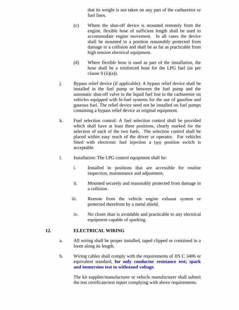
13. COMPLIANCE PLATE
There shall be installed near the filling connection and be clearly visible tothe refueller a Compliance plate displaying the following information:
Identification labels
i. Vehicles using a LPG system shall be labeled as follows:
Labels conforming with the specification given in clause 13(ii) ofthis Standard shall be affixed in a vertical position as close to thevehicle number plate as practical or on left side of the front and rearsafety glass and shall ensure visibility from the front and rear sides.
ii. The label shall be in position at all times, shall be in good condition,and the shape, colouring and lettering shall be easily identifiable.
iii. Label shall be coloured green, sized 80 mm x 80 mm square. Labelshall have on them the text “LPG” in a central position not be lessthan 20 mm high, coloured white. The label shall have a whiteborder 1 mm wide, 5 mm inside the outer edge and running parallelto it. The 80 mm dimension is measured from the outer edge.(Refer Appendix D for drawing).
COMPLIANCE PLATE
Ø Auto LPG Tank Identification Number(s)
Ø Date of Installation
Ø Water Capacity (litre) of the Total Installation
Ø Date of the Last Retest
Ø Vehicle Registration/Identification No
The LPG installation complies with the safety requirements of AIS 027
Ø Installed by
14. INSPECTION, TESTING AND COMMISSIONING (FORINSTALLER)
i. Commissioning
Prior to initial use, inspection of the LPG system and componentsshall be carried out by, or under the supervision of, an AuthorisedPerson/Installer, who shall also carry out a complete examination toensure that the system complies with all relevant sections of thisStandard and any statutory requirements as specified by theGovernment. of India.
ii. Initial inspection
The system shall be leak tested as detailed in Clause (14)(v) of thisStandard. The installation shall be inspected for compliance withthis Standard and all components shall be checked for desiredoperational performance. In the case of bi-fuel installations, theability of the vehicle to operate on the optional fuel shall also betested.
iii. Installation Certificate:
When the system conforms to this Standard an InstallationCertificate (as per Annexure VI of AIS 025 ) signed by theAuthorised Person/Installer shall be issued to owner of the vehicle.
iv. Periodic Inspection:
1) The Auto LPG Tank, piping and all components of thesystem shall be closely examined by an Installer forcorrosion, deterioration and for any modification affectingcompliance with this Standard at least once in a year orincase of malfunction or accident. The inspection shallinclude leak testing under clause (v) below.
2) When the system has been inspected and any defectsremedied and the system conforms to this Standard to thesatisfaction of Installer, checklist as per Appendix A ofthis Standard, shall be issued to the owner of the vehicle.
v. Leak testing
Initial test: At the time of commissioning, the complete system shallbe subjected to a pressure test using LPG or a gas inert to LPG suchas nitrogen in accordance with the following procedure:
1) Pressurize the system to a minimum pressure of 2.0 kg/cm2 (g).
2) Check all joints, components and drain plugs for leaks.
3) Where a leak is indicated, the fault shall be rectified and systemshall be re-tested for leaks.
WARNING: Ensure Auto LPG Tank and valve assembly approvedby the Dept. of Explosives prior to use.
vi. Subsequent testing: At the time of periodic inspection or afterrepairs to the system components downstream from the Auto LPGTank, LPG or an inert gas like Nitrogen may be used for testingprovided the following precautions are observed.
1) Testing shall be carried out under adequately vented conditions.
2) The test shall be at least 15 m from any open flame or othersource of ignition.
At the time of commissioning of an installation for the first time orafter any repairs, Auto LPG Tank(s) must be purged prior to fillingwith LPG.
vii. Operational Performance: The operation of the equipment andcontrols shall also be tested under LPG at normal working pressureto prove satisfactory performance of the entire system and a furtherleak test shall be carried out using a non-corrosive foaming agent.
viii. Testing of excess flow valve: The excess flow check valve shall betested to ensure that it closes and re-opens by rapidly opening andthen closing the service valve while the Auto LPG Tank remainsunder the pressure after the preceding test. This test should beperformed at initial inspection and subsequent periodic inspectionsor after any servicing of the valve itself or following Auto LPGTank removal/installment in the vehicle.
Procedure for test: The excess flow check valve shall be tested forcorrect functioning as follows:
a. Close the service valve on the fuel Auto LPG Tank.
b. Run the engine until all fuel in the service line is consumed.
c. Disconnect the battery leads and stow safely. The batteryshall be suitably covered and protected against electricalshorting.
d. Check that the engine has no potential sources of ignition, forexample, hot spots.
e. Disconnect the service fuel line where it meets the automaticfuel shut-off device or where it meets the vaporizer/regulatorwhichever is first.
f. Open the service valve on the fuel Auto LPG Tank rapidly andfully, then close it immediately.
The excess – flow check valve should function before or as soon asthe service valve is fully open. Functioning of theexcess-flow valve is confirmed when the initialescape of gas suddenly drops to the small flowpermitted by the bypass in the closing disc of theexcess-flow check valve.
g. Reconnect the service fuel line. Slowly open the service valveand retest for leaks at the connection.
Where appropriate and acceptable alternative to the above testmay be performed as follows:
Shut off the service valve and run the engine until the serviceline is empty. Open the service valve and listen for the soundof the excess-flow check valve operating. If it has not closed,close the service valve, run the engine until the service line isempty, and carry out the test as detailed above.
WARANING – Since large volumes of gas may escape duringthis test, it should only be done in the open air at a locationwhich is at least 15 m from the open flame or any other sourceof ignition and as approved by Dept. of Explosives.
ix. Fire Extinguisher : A 10 kg of extinguisher conforming to IS:2171of dry chemical powder type shall be kept ready at a safe distanceat the time of performing the test. If ignition occurs the servicevalve should be immediately closed and the extinguisher be used toquell any fire.
x. Additional Auto LPG Tank : For more than 1 Auto LPG Tank thefollowing shall apply:
a. Each excess flow valve shall be tested separately bydisconnecting the fuel line prior to the non-return valve andthe test carried out as per clause (viii) above.
b. The function of each non-return valve shall be tested bypressurizing the valve and testing for leaks.
c. When (a) and (b) are satisfactory the total system shall betested according to clause (viii) with all Auto LPG Tankservice valves opened simultaneously.
xi. Test of automatic fill limiter: Only functionality of the automaticfill limiter shall be checked as per following procedure:
Initially LPG tank shall be fully emptied of LPG (in liquidform) and then filled with LPG. Automatic fill limiter shouldcut-off the entry of LPG (in liquid form) to the LPG tank,when pre-determined maximum level of 80% of water capacityof LPG tank fitted on vehicle is reached.
xii. Gas tightness of compartments and sub-compartments
The compartment or sub-compartment shall be tested by the testagency for gas tightness as outlined in Clause 8(D).
At each periodic inspection the compartment or sub-compartmentshall be tested by the installer using the following procedure:
a. A thorough inspection shall be made of all seals and gaskets toensure that they are fitted correctly and no degradation of thematerial has taken place. Any seal or gasket showing signs ofdegradation shall be replaced.
b. All mating faces of the hatch shall be inspected to ensure thatfull surface contacts being maintained when the hatch is in thelocked position.
c. Ducting shall be thoroughly inspected for any signs of damageor degradation. Where damage or degradation is noted theducting shall be replaced.
d. The ducting connections to the compartment, sub-compartment and the vent shall be checked for gas tightness.
Note - It may be permissible to check a compartment or a sub-compartment before installation of the fuel system, providedthat nothing in the subsequent installation procedure willnegate the validity of the test.
15. GARAGING AND REPAIR (FOR INSTALLER)
i. Garaging and repairing of LPG fueled vehicles.
Vehicles fueled with LPG may be stationed or serviced and repairedinside garages provided that the following safety recommendationsare observed:
a. There shall be no leaks in the fuel system and the Auto LPGTank is not to be filled beyond the maximum filling level asprescribed by the Dept. of Explosives.
b. Vehicles shall not be parked within 3 m of any sources ofignition.
c. Unless the fuel is required for engine operation, LPG fueledvehicles being repaired in garages shall have the Auto LPGTank shut off valve closed and the LPG fuel in the serviceline exhausted by running the engine and disconnecting theline in the ventilated area.
d. Vehicles undergoing repairs involving welding or theapplication of the heat to any part within 1 m of the AutoLPG Tank shall have the Auto LPG Tank removed orshielded from the source of heat.
e. If the vehicle is repaired within 5 m of an open pit, the pitshall be adequately ventilated.
ii. Repair operation
a. Any repair operation involving heat shall be carried outwith due regard to fire safety.
b. Damaged fuel lines shall not be repaired; in all cases theyshall be replaced.
c. Welding, brazing and the application of heat shall not becarried out on any part of the Auto LPG Tank subsequent tomanufacture.
d. When a vehicle is involved in an accident causing damageto part or all of the LPG Fuel systems or where any part ofthe system necessitates removal to allow for the repair ofthe vehicle the system shall, after re-assembly or repair, betested in accordance with clause 14(v) of this Standard andchecklist as per Appendix A of this standard be issued.The requirements of sub-clause 15 (iii) (b) of this Standardshall also be met.
iii. Scrapping
a. A vehicle, which is about to be scrapped, shall have itsAuto LPG Tank removed prior to disposal.
b. Where the Auto LPG Tank has been subjected to impact orfire damage the Auto LPG Tank shall be inspected and re-tested as prescribed under Gas Cylinders Rules.
Note – There will always be combustible gas in the Auto LPG Tankuntil it has been cleared of all traces of flammable vapour or gas.
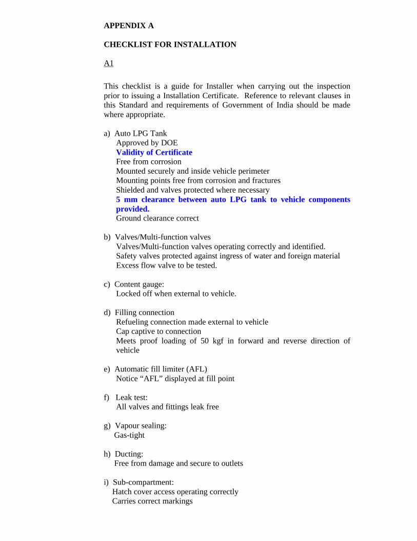
APPENDIX A
CHECKLIST FOR INSTALLATION
A1
This checklist is a guide for Installer when carrying out the inspectionprior to issuing a Installation Certificate. Reference to relevant clauses inthis Standard and requirements of Government of India should be madewhere appropriate.
a) Auto LPG TankApproved by DOEValidity of CertificateFree from corrosionMounted securely and inside vehicle perimeterMounting points free from corrosion and fracturesShielded and valves protected where necessary5 mm clearance between auto LPG tank to vehicle componentsprovided.Ground clearance correct
b) Valves/Multi-function valvesValves/Multi-function valves operating correctly and identified.Safety valves protected against ingress of water and foreign materialExcess flow valve to be tested.
c) Content gauge:Locked off when external to vehicle.
d) Filling connectionRefueling connection made external to vehicleCap captive to connectionMeets proof loading of 50 kgf in forward and reverse direction ofvehicle
e) Automatic fill limiter (AFL)Notice “AFL” displayed at fill point
f) Leak test:All valves and fittings leak free
g) Vapour sealing: Gas-tight
h) Ducting: Free from damage and secure to outlets
i) Sub-compartment: Hatch cover access operating correctly Carries correct markings
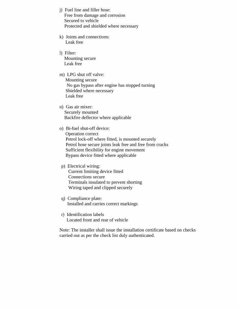
j) Fuel line and filler hose: Free from damage and corrosion Secured to vehicle Protected and shielded where necessary
k) Joints and connections: Leak free
l) Filter: Mounting secure Leak free
m) LPG shut off valve: Mounting secure No gas bypass after engine has stopped turning Shielded where necessary Leak free
n) Gas air mixer: Securely mounted Backfire deflector where applicable
o) Bi-fuel shut-off device: Operation correct Petrol lock-off where fitted, is mounted securely Petrol hose secure joints leak free and free from cracks Sufficient flexibility for engine movement Bypass device fitted where applicable
p) Electrical wiring:Current limiting device fittedConnections secureTerminals insulated to prevent shortingWiring taped and clipped securely
q) Compliance plate: Installed and carries correct markings
r) Identification labels Located front and rear of vehicle
Note: The installer shall issue the installation certificate based on checkscarried out as per the check list duly authenticated.
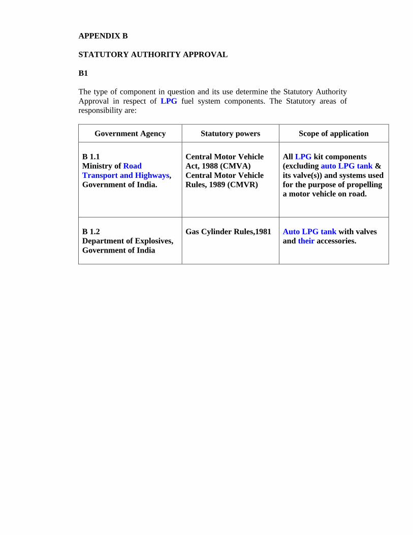
APPENDIX B
STATUTORY AUTHORITY APPROVAL
B1
The type of component in question and its use determine the Statutory AuthorityApproval in respect of LPG fuel system components. The Statutory areas ofresponsibility are:
Government Agency Statutory powers Scope of application
B 1.1Ministry of RoadTransport and Highways,Government of India.
Central Motor VehicleAct, 1988 (CMVA)Central Motor VehicleRules, 1989 (CMVR)
All LPG kit components(excluding auto LPG tank &its valve(s)) and systems usedfor the purpose of propellinga motor vehicle on road.
B 1.2Department of Explosives,Government of India
Gas Cylinder Rules,1981 Auto LPG tank with valvesand their accessories.
APPENDIX C
LPG CHARACTERISTICS AND SAFETY ASPECTS
C1The specification of LPG shall conform to IS:14861.
C2LPG is stored, normally, as a liquid under pressure, is colorless and its weight as aliquid is approximately half that of an equivalent volume of water.
C3In changing from a liquid state to gas LPG expands approximately 260 times itsoriginal volume at normal atmospheric conditions.
C4A mixture of LPG vapour in air of between 2% and 10% by volume is flammable.Outside this range any mixture is either too weak or too rich to propagate flame.However, over-rich mixtures can become hazardous when diluted with air.
C5LPG vapour is approximately 1.5 times denser than air.
C6LPG vapour in common with most light hydrocarbon vapours, is slightlyanaesthetic and also cause suffocation if present in sufficiently highconcentrations.
C7LPG is odorised (by adding ethyl mercaptan) at source to be detectable by smell ata concentration in air of about 20% of lower flammability limit, i.e. a vapour/airmixture of 0.5% by volume.
C8LPG may also be detected through condensation of water vapour from the air inthe vicinity of a leak or because of a visible shimmering effect caused undercertain incident light conditions.
C9Owing to its rapid vaporization and consequent lowering of temperature, LPG,particularly liquid, can cause severe frost burns if brought into contact with theskin. Protective clothing such as gloves and goggles should be worn if exposureto this hazard is likely to occur.
C10Action in the event of a serious leak.
C10.1On no account should a naked flame be used to detect a leak. Shut off all enginesand any electrical equipment in the immediate vicinity and leave off until the gashazard is removed.
C10.2Smoking or naked lights must not be allowed. Extinguish all heaters, lights, gasrings, stoves and boilers in the immediate vicinity.
C10.3Move all people to a safe distance from the leak in an upwind or crosswinddirection.
C10.4Unless the leakage is of a minor nature or the leak can be quickly controlled bythose present on site, the Fire Service and Police Department should be notified,advising them of the location, material and volume involved.
C11Action in the event of fire.
C11.1In the event of fire, expert help from the Fire Service must be sought immediatelyand the Police Department notified. Advise them of the location. Carry out thesame precautions as under “Serious Leak”.
C11.2Do not attempt to extinguish flames other than by cutting off the flow of LPGresulting fires with dry powder type extinguisher.
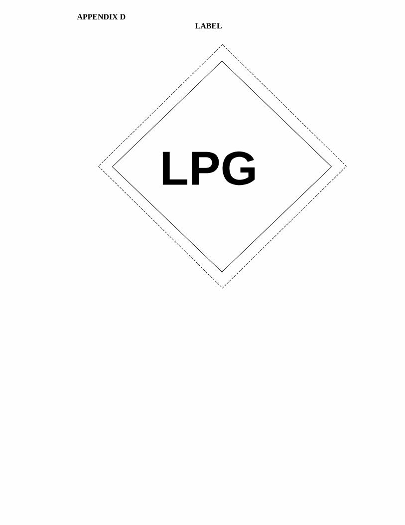
APPENDIX DLABEL
LPG
APPENDIX E
FREEZING CONDITIONS AND CORROSIVE CONDITIONS (notapplicable to vapour withdrawal system)
E1Where vaporizer heat is drawn from the engine cooling water, care should betaken to ensure that the water does not freeze in the vaporizer during cold weather.Expansion of the water on freezing can cause serious damage to the pressureregulator assembly.
E2Most LPG vaporizer/regulators are made from non-ferrous alloys, which cansuffer pin hole corrosion under certain conditions. If this is allowed to take placeLPG can be admitted to the cooling water system where it will pressurize theradiator and cause a potential hazard. It is important, therefore, to have aneffective anti-corrosion additive in the cooling water.
E3It is important to ensure that the coolant additive and the dilutant ratio complyfully with the engine manufacturer’s requirements.
APPENDIX F
BACKFIRE – DEFLECTOR TESTS
1) A backfire deflector under backfire conditions shall contain a visible flamefront within its confines and shall not be displaced, physically damaged ordistorted, or show evidence of burning or smoldering of internal parts. If thedeflector is of the oil-bath type, it shall be free of any overflow or dischargepermitting accumulation of oil on electrical, hot-engine or exhaust systemparts.
2) A complete industrial truck / vehicle is to be used for this test. Tests are notrequired on backfire deflectors employed diesel engines.
3) The backfire deflector (air cleaner, oil-bath or dry element type) and connectinghose are to be removed from the engine. The spark timing is to be advanced(approximately 8 degrees) and the spark plug leads are to be interchanged toobtain sharp backfires under the following conditions. The engine is to bealternately raced and idled and the ignition switch is to be operated toalternately energize and de-energize the ignition system. During the test, theintensity of the backfire and the issuance and extent of the accompanying flameare to be noted.
4) The backfire deflector (air cleaner) is then to be installed on the truck in theintended location. An oil-bath type deflector (air cleaner) is to be filled to themarked “full level-line” of the bowl. Paper is to be placed beneath the intakeorifices of an oil-bath type and over adjacent surfaces of parts likely to beaffected by accumulations of oil.
5) The engine is then to be operated in the several manners determined in thepreliminary test to provide for the most severe backfire conditions. At least tenand not more than twenty backfires are to be produced.
6) Observations for containment of flame are to be made under semi-darkenedconditions by at least two observers. No visible flame is to be in evidence atany time during the tests. In the tests of an oil-bath type, paper is not to showevidence of oil deposits in the form of droplets.
7) A dry-type filter element is to be tested in the above manner, then removed andthen subjected to five consecutive washing and drying cycles. Washing is toconsist of immersion in plain water together with sufficient agitation to removebulk material adhering to the outside surface. The test element is then to beremounted as intended in operation, and the backfire test is to be repeated.
8) The side of the filter media normally exposed to backfire is then to be subjectedto a flame source of sufficient intensity to cause the media to burn or glow. Theflame source is then to be removed and an acceptable filter media is not tocontinue to burn or smolder.