Embed Size (px)
Citation preview

MONTAGEANLEITUNG MOUNTING INSTRUCTIONS
AK MSR 15AK MSS 15AbtastkopfScanning head
Ausgabe 05/2020 Art.Nr. 1278930-01 Dok.Nr. D1278930-02-A-01
AK MSR 1502 AK MSR 15, AK MSS 15
Seite / Page
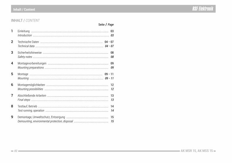
1 Einleitung ............................................................................................ 03 Introduction ........................................................................................... 03
2 Technische Daten .......................................................................... 04 − 07 Technical data ................................................................................. 04 − 07
3 Sicherheitshinweise .............................................................................. 08 Safety notes .......................................................................................... 08
4 Montagevorbereitungen ........................................................................ 09 Mounting preparations ............................................................................ 09
5 Montage ....................................................................................... 09 − 11 Mounting ........................................................................................ 09 − 11
6 Montagemöglichkeiten .......................................................................... 12 Mounting possibilities ............................................................................ 12
7 Abschließende Arbeiten ......................................................................... 13 Final steps ............................................................................................ 13
8 Testlauf, Betrieb .................................................................................... 14 Test running, operation ........................................................................... 14
9 Demontage, Umweltschutz, Entsorgung .................................................. 15 Demounting, environmental protection, disposal ......................................... 15
INHALT / CONTENT
Inhalt / Content

03AK MSR 15, AK MSS 15
Einleitung / Introduction 1
Lesen Sie die Montageanleitung sorgfältig und bewahren Sie sie gut auf. Online verfügbar unter: http://www.rsf.at/de/service-support/downloadbereichCarefully read the mounting instructions and keep them safely. Online available at: http://www.rsf.at/en/service-support/downloads
Dieses Symbol kennzeichnet wichtige Hinweise, die Personenschäden verhindern.This symbol indicates important information that prevents personal injuries.
Dieses Signalwort kennzeichnet wichtige Hinweise, die Sachschäden verhindern. This signal word indicates important information that prevents damage to property.
Dieses Symbol kennzeichnet nützliche Tipps, Empfehlungen sowie zusätzliche Informationen. This symbol indicates useful tips, recommendations and addi-tional information.Dieses Symbol kennzeichnet Handlungsanweisungen. This symbol indicates instructions.
1.1 VORWORT / PREAMBLE
1.3 SYMBOLE / SYMBOLS
HINWEIS
NOTICE
Die MSx 15 Messgeräte entsprechen den Vorgaben folgender EU-Richtlinien: EMV-Richtlinie 2014/30/EU RoHS-Richtlinie 2011/65/EU, 2015/863/EUThe MSx 15 encoders comply with the specifications of the following EU directives: EMV-directive 2014/30/EU RoHS-directive 2011/65/EU, 2015/863/EU
1.2 KONFORMITÄT MIT RICHTLINIEN / DIRECTIVES CONFORMITY
Die MSx 15 Messgeräte dürfen nur zur Ermittlung von Winkel- bzw. Weginformati-onen in rotativen Anwendungen verwendet werden. Jeder andere Gebrauch kann Personen- bzw. Sachschäden verursachen!The MSx 15 encoders may only be used to determine angle and path information in rotative applications. Any other use may cause personal injury or property damage!
SPANNUNGSVERSORGUNGSchließen Sie RSF Elektronik Messgeräte nur an Folge-Elektroniken an, deren Ver-sorgungsspannung aus PELV-Systemen (EN 50 178) erzeugt wird. RSF Elektronik Messgeräte erfüllen die Anforderungen der Norm IEC 61010-1 nur, wenn die Spannungsversorgung aus einem Sekundärkreis mit begrenzter Energie nach IEC 61010-13rd Ed., Abschnitt 9.4 oder mit begrenzter Leistung nach IEC 60950-1 2nd Ed., Abschnitt 2.5 oder aus einem Sekundärkreis der Klasse 2 nach UL1310 erfolgt.1)
1) Anstelle der IEC 61010-13rdEd., Abschnitt 9.4 können auch die entsprechenden Abschnitte der Normen DIN EN 61010-1, EN61010-1, UL 61010-1 und CAN/CSA-C22.2 No. 61010-1 bzw. anstelle der IEC 60950-12nd Ed., Abschnitt 2.5 die entsprechenden Abschnitte der Normen DIN EN60950-1, EN60950-1, UL60950-1, CAN/CSA-C22.2 No. 60950-1 verwendet werden.
VOLTAGE SUPPLYConnect RSF Elektronik encoders only to subsequent electronics whose power supply is generated from PELV systems (EN 50 178).RSF Elektronik encoders fulfill the requirements of standard IEC 61010-1 only if the po-wer is supplied from a secondary circuit with current limitation as per IEC 610103rd Ed., Section 9.4 or with power limitation as per IEC 60950-12nd Ed., Section 2.5 or from a Class 2 secondary circuit as specified in UL1310.1)
1) In place of IEC 61010-13rdEd., Section 9.4, the corresponding sections of standards DIN EN 61010-1, EN61010-1, UL 61010-1 and CAN/CSA-C22.2 No. 61010-1 can be applied and in place of IEC 60950-12nd Ed., Section 2.5 the corresponding sections of standards DIN EN60950-1, EN60950-1, UL60950-1, CAN/CSA-C22.2 No. 60950-1 can be applied.
1.4 BESTIMMUNGSGEMÄßER GEBRAUCH / INTENDED USE
1.5 ALLGEMEINE ELEKTRISCHE HINWEISE GENERAL ELECTRICAL INFORMATION

AK MSR 1504 AK MSR 15, AK MSS 15
2 Technische Daten / Technical data
2.1 SPEZIFIKATION/ SPECIFICATION
Gerätetyp Model
MSR 15 1 Vss
MSR 15 TTLx1u
MSR 15 TTLx5
MSR 15 TTLx10
MSR 15 TTLx20
MSR 15 TTLx25
MSR 15 TTLx50
MSR 15 TTLx100
MSR 15 TTLx200
MessschrittMeasuring step
Je nach ext. Unterteilung / Dep. on ext. interpolation
360°⁄ (Lines × 4) 360°⁄ (Lines × 20) 360°⁄ (Lines × 40) 360°⁄ (Lines × 80) 360°⁄ (Lines × 100) 360°⁄ (Lines × 200) 360°⁄ (Lines × 400) 360°⁄ (Lines × 800)
Signalform 1 Vss / 1 Vpp
Integrierte InterpolationIntegrated interpolation --
1fachTimes 1
5fachTimes 5
10fachTimes 10
20fachTimes 20
25fachTimes 25
50fachTimes 50
100fachTimes 100
200fachTimes 200
Max. Ausgangsfrequenz Max. output frequency 400 KHz -- -- -- -- -- -- -- --
Flankenabstand amin [ns]Edge separation -- 300 300 300 200 200 100 100 50
Abtastdurchmesser [mm]Scanning diameter [mm]
rpm rpm rpm rpm rpm rpm rpm rpm rpm
50,00 6000 6000 2400 1200 900 700 700 360 360
59,93 5000 5000 2000 1000 750 600 600 300 300
75,06 4000 4000 1600 800 600 450 450 240 240
99,96 3050 3050 1200 600 450 350 350 180 180
103,88 2900 2900 1150 570 430 340 340 170 170
114,17 2650 2650 1050 500 400 320 320 160 160
150,38 2000 2000 800 400 300 240 240 120 120
200,35 1500 1500 600 300 220 180 180 90 90
228,77 1300 1300 500 260 200 160 160 80 80
249,85 1200 1200 480 240 180 140 140 70 70
299,81 1000 1000 400 200 150 120 120 60 60
350,23 870 870 340 170 130 100 100 50 50
2.1.2 ALLGEMEINE DATEN AK MSR 15 GENERAL DATA AK MSR 15
2.1.1 ABTASTKOPF AK MSR 15 / SCANNING HEAD AK MSR 15
Spannungsversorgung: Power supply: TTL: +5 V ±10 %, max. 160 mA (ohne Last / unloaded) 1 Vss / 1 Vpp: +5 V ±10 %, max. 160 mA (ohne Last / unloaded)
Schutzart (EN 60529): IP40Protection (EN 60529): IP40
Zulässige Vibration:Permissible vibration:150 m/s2 (55 bis / to 2000 Hz)
Zulässiger Schock: Permissible shock:750 m/s2 (8 ms)
Zulässige Temperatur: Permissible temperature: –20 °C bis / to +70 °C (bei Lagerung) (storage), 0 °C bis / to +70 °C (im Betrieb) (operation)
Masse / Mass: Abtastkopf / Reading head AK: 17 gKabel / Cable: 25 g/mSub-D-Stecker / D-sub connector: 28 g
Lines = Strichzahl lt. Maßverkörperung / Lines acc. to graduation carrier

05AK MSR 15, AK MSS 15
2.1.5 TYPENSCHILD / LABEL
Referenzmarke / Reference markA: Aktiv / ActiveK: Deaktiviert / Deactivated
A:
Geeignet für Teilungsart / Suitable for graduation typeM: Stahlmaßband geschwärzt Steel tape blackened
M:
Flankenabstand amin (2% Tol.) Edge separation amin (2% tol.)
0.100µs:
Integrierte Interpolation 100-fach Integrated interpolation times 100
TTLx100:ID: Teilenummer / Part number AK MSS15: Produktname / Product name
T8: Herstellungsdatum / Manufacturing date
SN: Seriennummer mit Änderungsindex „A“ Serial number with change index “A“
Endlagenschalter S1 und S2 (Schaltsignale) Limit switches S1 and S2 (switch signals)K: Ohne Funktion / Without function
K K:S2S1
2.2 ZUBEHÖR MECHANISCH MECHANICAL ACCESSORY2.2.1 MONTAGEHILFE MOUNTING AID ID: 1280127-xx (abhängig vom Durchmesser) (dependent on diameter)
Gerätetyp Model
Ausgangssignale Output signals
Messschritt [°] Measuring step [°]
Integrierte Interpolation Integrated interpolation
Max. Umfangsgeschwin-digkeit an D* [m/s]
Max. circumferential speed at D* [m/s]
Max. Ausgangs- frequenz [kHz]
Max. output frequency [kHz]
MSS 15 1 VssJe nach ext. Unterteilung
Dep. on external interpolation -- 10,00 250
Flankenabstand amin Edge separation amin
MSS 15 TTLx1u 360° ⁄ (LPR × 4) 1fach / times 1 10,00 500 ns
MSS 15 TTLx5 360° ⁄ (LPR × 20) 5fach / times 5 6,40 300 ns
MSS 15 TTLx10 360° ⁄ (LPR × 40) 10fach / times 10 3,20 300 ns
MSS 15 TTLx20 360° ⁄ (LPR × 80) 20fach / times 20 2,40 200 ns
MSS 15 TTLx25 360° ⁄ (LPR × 100) 25fach / times 25 1,92 200 ns
MSS 15 TTLx50 360° ⁄ (LPR × 200) 50fach / times 50 1,92 100 ns
MSS 15 TTLx100 360° ⁄ (LPR × 400) 100fach / times 100 0,96 100 ns
MSS 15 TTLx200 360° ⁄ (LPR × 800) 200fach / times 200 0,96 50 ns
2.1.4 ALLGEMEINE DATEN / GENERAL DATA AK MSS 152.1.3 ABTASTKOPF AK MSS 15 / SCANNING HEAD AK MSS 15Interpolationsabweichung: Interpolation error: ±60" ⁄ D
Spannungsversorgung: Power supply: TTL: +5 V ±10 %, max. 160 mA (ohne Last / unloaded) 1 Vss / 1 Vpp: +5 V ±10 %, max. 160 mA (ohne Last / unloaded)
Schutzart (EN 60529): IP40Protection (EN 60529): IP40
Zulässige Vibration:Permissible vibration:150 m/s2 (55 bis / to 2000 Hz)Zulässiger Schock: Permissible shock:750 m/s2 (8 ms)
Zulässige Temperatur: Permissible temperature: –20 °C bis / to +70 °C (bei Lagerung) (storage), 0 °C bis / to +70 °C (im Betrieb) (operation)
Masse / Mass: Abtastkopf / Reading head AK: 17 gKabel / Cable: 25 g/mSub-D-Stecker / Connector: 28 g
LPR = Theoretische Strichzahl pro Umdrehung 360° lt. Maßverkörperung / Theoretical lines per revolution 360° acc. to graduation carrier D = Abtastdurchmesser / Scanning diameter
Technische Daten / Technical data 2
AK MSR 1506 AK MSR 15, AK MSS 15
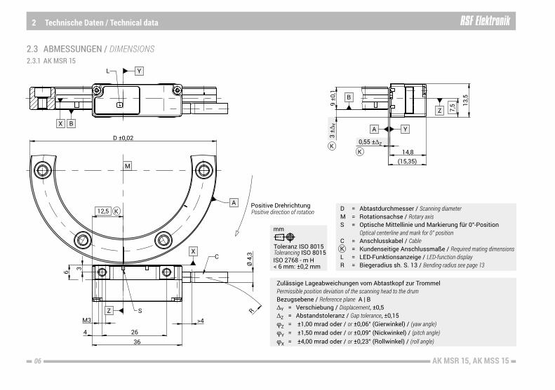
2.3 ABMESSUNGEN / DIMENSIONS
2 Technische Daten / Technical data
2.3.1 AK MSR 15

07AK MSR 15, AK MSS 15
Technische Daten / Technical data 2
2.3.2 AK MSS 15
AK MSR 1508 AK MSR 15, AK MSS 15
3 Sicherheitshinweise / Safety notes
Die Montage der Messgeräte erfordert gute mechanische und elektronische Kennt-nisse und eine präzise und sichere Arbeitsweise! Führen Sie die Montage nur durch eine ausgebildete Fachkraft unter Einhaltung der örtlichen Sicherheitsbestim-mungen durch! The mounting of the encoders requires great mechanical and electronical knowledge, moreover precise and safe operation! Therefore, mounting should only be carried out by a qualified specialist in compliance with local safety regulations!
3.1 PERSONENSCHUTZ / PERSONAL SAFETY 3.2 GERÄTESCHUTZ / DEVICE SAFETY
Schalten Sie alle von der Montage bzw. Reparatur betroffenen Geräte / Maschinen / Anlagen vollständig ab! Trennen Sie die Geräte / Maschinen / Anlagen gegebenenfalls vom Stromnetz und machen Sie die Pneumatik drucklos! Before mounting, switch off all the devices / machines / plants affected. If appropriate, isolate the devices / machines / plants from the mains and remove the pressure from pneumatic.
Benützen Sie geeignete Schutzausrüstung für die Montage / Demontage (Handschuhe, Schutzbrille). Wear suitable protective equipment for mounting / demounting (gloves, goggles).
HINWEIS
NOTICE
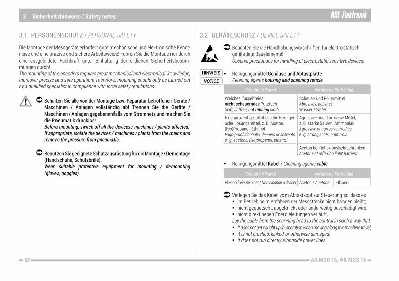
Beachten Sie die Handhabungsvorschriften für elektrostatisch gefährdete Bauelemente! Observe precautions for handling of electrostatic sensitive devices!
Reinigungsmittel Gehäuse und Abtastplatte Cleaning agents housing and scanning reticle
Erlaubt / Allowed Verboten / Prohibited
Weiches, fusselfreies, nicht scheuerndes PutztuchSoft, lintfree, not rubbing cloth
Scheuer- und Poliermittel Abrasives, polishes Wasser / Water
Hochprozentige, alkoholische Reiniger oder Lösungsmittel, z. B. Aceton, (Iso)Propanol, EthanolHigh-proof alcoholic cleaners or solvents, e. g. acetone, (iso)propanol, ethanol
Agressive oder korrosive Mittel, z. B. starke Säuren, Ammoniak Agressive or corrosive mediea, e. g. strong acids, ammonia
Aceton bei Reflexionslichtschranken Acetone at reflexion light barriers
Reinigungsmittel Kabel / Cleaning agents cable
Erlaubt / Allowed Verboten / Prohibited
Alkoholfreie Reiniger / Non-alcoholic cleaner Aceton / Acetone Ethanol
Verlegen Sie das Kabel vom Abtastkopf zur Steuerung so, dass es im Betrieb beim Abfahren der Messstrecke nicht hängen bleibt; nicht gequetscht, abgeknickt oder anderweitig beschädigt wird; nicht direkt neben Energieleitungen verläuft. Lay the cable from the scanning head to the control in such a way that it does not get caught up in operation when moving along the machine travel; it is not crushed, kinked or otherwise damaged; it does not run directly alongside power lines.
09AK MSR 15, AK MSS 15
Montage / Mounting 5Montagevorbereitungen / Mounting preparations 4
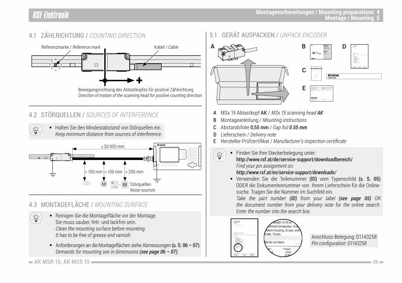
4.1 ZÄHLRICHTUNG / COUNTING DIRECTION
4.2 STÖRQUELLEN / SOURCES OF INTERFERENCE
+
Kabel / CableReferenzmarke / Reference mark
Bewegungsrichtung des Abtastkopfes für positive Zählrichtung Direction of motion of the scanning head for positive counting direction
4.3 MONTAGEFLÄCHE / MOUNTING SURFACE
> 200 mm
≤ 30 000 mm
Störquellen Noise sources
> 100 mm> 100 mm
Halten Sie den Mindestabstand von Störquellen ein. Keep minimum distance from sources of interference.
Reinigen Sie die Montagefläche vor der Montage. Sie muss sauber, fett- und lackfrei sein. Clean the mounting surface before mounting. It has to be free of grease and varnish.
Anforderungen an die Montageflächen siehe Abmessungen (s. S. 06 – 07). Demands for mounting see in dimensions (see page 06 – 07).
D
5.1 GERÄT AUSPACKEN / UNPACK ENCODERB
C
A
A MSx 15 Abtastkopf AK / MSx 15 scanning head AKB Montageanleitung / Mounting instructionsC Abstandsfolie 0,55 mm / Gap foil 0.55 mmD Lieferschein / Delivery noteE Hersteller-Prüfzertifikat / Manufacturer’s inspection certificate
Finden Sie Ihre Steckerbelegung unter: http://www.rsf.at/de/service-support/downloadbereich/ Find your pin assignment on: http://www.rsf.at/en/service-support/downloads/ Verwenden Sie die Teilenummer (ID) vom Typenschild (s. S. 05) ODER die Dokumentennummer von Ihrem Lieferschein für die Online- suche. Tragen Sie die Nummer im Suchfeld ein. Take the part number (ID) from your label (see page 05) OR the document number from your delivery note for the online search. Enter the number into the search box.
Anschluss-Belegung: D1143258Pin configuration: D1143258
E

10 AK MSR 15, AK MSS 15
HINWEIS
NOTICE
Entfernen Sie die Schutzhaube vorsichtig. Remove the protection cover carefully.
Reinigen Sie die Abtastplatte bei Bedarf. Clean the scanning reticle if necessary.
5 Montage / Mounting
5.2 SCHUTZHAUBE ENTFERNEN / REMOVE PROTECTION COVER
Schutzhaube / Protection cover
Beschädigungsgefahr durch spitzes Werkzeug!Die Abtastplatte ist hochsensibel und kann durch Kratzer beschädigt werden. Entfernen Sie die Schutzhaube nur mit einem stumpfen Werkzeug.
Risk of damage due to sharp tool!The scanning reticle is highly sensitive and can be damaged by scratches. Remove the protection cover only with a blunt tool.
Abtastplatte / Scanning reticle
HINWEIS
NOTICE
5.3 ABSTAND / GAP
Beschädigung des Geräts durch falschen Abstand!Der Arbeitsabstand zwischen Abtastkopf und Band muss 0,55 ±ΔZ mm sein. Durch einen zu kleinen Abstand zerkratzt die Abtastplatte oder das Band (MSS 15) oder beides. Verwenden Sie die optionale Montagehilfe oder die mitgelieferte Abstandsfolie.
Risk of damage due to a wrong gap!The working gap between scanning head and scale has to be 0.55 ±ΔZ mm. Due to a minor gap the scanning reticle or the scale (MSS 15) scratches or both. Use the optional mounting aid or the included gap foil.
Beachten Sie die Übereinstimmung vom Winkelmessgerät-Außendurchmesser und Durchmesserangabe auf der Montagehilfe. Observe the compliance of the angle encoder outside diameter and the stated diameter on the mounting aid.
Beachten Sie den Anschlag! Der Abtastkopf muss in markierter Ecke aufliegen. Observe the fixed stop! The scanning head must rest in the marked corner.
Montieren Sie den Abtastkopf mit der Montagehilfe (optionales Zubehör). Mount the scanning head by use of the mounting aid (optional accessory).
11AK MSR 15, AK MSS 15
Montage / Mounting 5
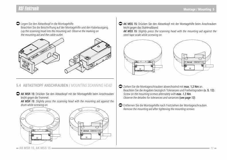
5.4 ABTASTKOPF ANSCHRAUBEN / MOUNTING SCANNING HEAD
AK MSS 15: Drücken Sie den Abtastkopf mit der Montagehilfe beim Anschrauben leicht gegen das Stahlmaßband. AK MSS 15: Slightly press the scanning head with the mounting aid against the steel tape scale while screwing on.
Ziehen Sie die Montageschrauben abwechselnd mit max. 1,2 Nm an. Beachten Sie die Angaben bezüglich Toleranzen und Freiheitsgraden (s. S. 12). Screw on the mounting screws alternately with max. 1.2 Nm. Observe the detailes for tolerances and variances (see page 12).
Entfernen Sie die Montagehilfe nach Festziehen der Montageschrauben. Remove the mounting aid after tightening the mounting screws.
AK MSR 15: Drücken Sie den Abtastkopf mit der Montagehilfe beim Anschrauben leicht gegen die Trommel. AK MSR 15: Slightly press the scanning head with the mounting aid against the drum while screwing on.
Legen Sie den Abtastkopf in die Montagehilfe. Beachten Sie die Beschriftung auf der Montagehilfe und den Kabelausgang. Lay the scanning head into the mounting aid. Observe the marking on the mounting aid and the cable outlet.

12 AK MSR 15, AK MSS 15
6 Montagemöglichkeiten / Mounting possibilities
6.1 MONTAGEMÖGLICHKEITEN AK MSR 15, AK MSS 15 / MOUNTING POSSIBILITIES AK MSR 15, AK MSS 15
6.2 MONTAGE AK ZU MAßVERKÖRPERUNG / MOUNTING AK TO GRADUATION CARRIER
= Kundenseitige Anschlussmaße / Required mating dimensions
6.2.1 MSR 15 6.2.2 MSS 15
ΔY, Z = s. S. 05 – 06 / see page 05 – 06
13AK MSR 15, AK MSS 15
Abschließende Arbeiten / Final steps 7
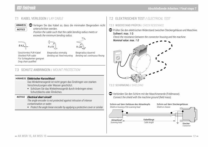
7.1 KABEL VERLEGEN / LAY CABLE
7.3 SCHUTZ ANBRINGEN / MOUNT PROTECTION
7.2 ELEKTRISCHER TEST / ELECTRICAL TEST
7.2.2 SCHIRMUNG / SHIELDING
7.2.1 WIDERSTAND PRÜFEN / CHECK RESISTANCE
Prüfen Sie den elektrischen Widerstand zwischen Steckergehäuse und Maschine. Sollwert: max. 1 Ω Check the resistance between the connector housing and the machine. Nominal value: max. 1 Ω
Verbinden Sie den Schirm mit der Maschinenerde (Feldmasse). Connect the shield with the machine ground (field mass).
HINWEIS
NOTICE
Elektrischer Kurzschluss!Das Winkelmessgerät ist nicht gegen das Eindringen von starken Verschmutzungen oder Wasser geschützt. Schützen Sie das Winkelmessgerät durch Anbringen eines Schutzblechs oder Ähnliches.
Electrical short circuit!The angle encoder is not protected against intrusion of intense contamination or water. Protect the angle linear encoder by applying a protective cover or similar.
Verlegen Sie das Kabel so, dass die minimalen Biegeradien nicht unterschritten werden. Position the cable such that the cable bending radius meets or exceeds the minimum bending radius.
Geschirmtes PUR-Kabel Shielded PUR-cable Für Schleppketten geeignet Drag chain qualified
Biegeradius einmaligBending rad. fixed mounting
Biegeradius dauernd Bending rad. continuous flexing
HINWEIS
NOTICE
14 AK MSR 15, AK MSS 15
8 Testlauf, Betrieb / Test running, operation
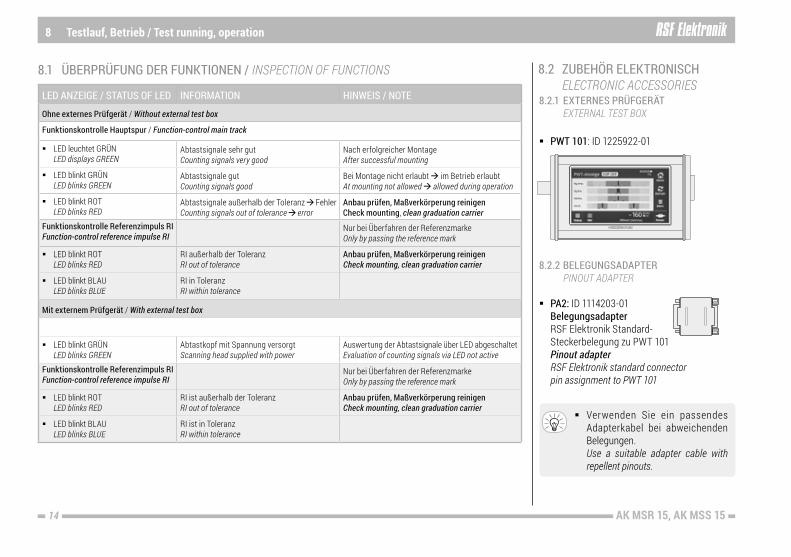
8.1 ÜBERPRÜFUNG DER FUNKTIONEN / INSPECTION OF FUNCTIONS
LED ANZEIGE / STATUS OF LED INFORMATION HINWEIS / NOTE
Ohne externes Prüfgerät / Without external test box
Funktionskontrolle Hauptspur / Function-control main track
LED leuchtet GRÜN LED displays GREEN
Abtastsignale sehr gut Counting signals very good
Nach erfolgreicher Montage After successful mounting
LED blinkt GRÜN LED blinks GREEN
Abtastsignale gut Counting signals good
Bei Montage nicht erlaubt im Betrieb erlaubt At mounting not allowed allowed during operation
LED blinkt ROT LED blinks RED
Abtastsignale außerhalb der Toleranz Fehler Counting signals out of tolerance error
Anbau prüfen, Maßverkörperung reinigen Check mounting, clean graduation carrier
Funktionskontrolle Referenzimpuls RI Function-control reference impulse RI
Nur bei Überfahren der Referenzmarke Only by passing the reference mark
LED blinkt ROT LED blinks RED
RI außerhalb der Toleranz RI out of tolerance
Anbau prüfen, Maßverkörperung reinigen Check mounting, clean graduation carrier
LED blinkt BLAU LED blinks BLUE
RI in Toleranz RI within tolerance
Mit externem Prüfgerät / With external test box
LED blinkt GRÜN LED blinks GREEN
Abtastkopf mit Spannung versorgt Scanning head supplied with power
Auswertung der Abtastsignale über LED abgeschaltet Evaluation of counting signals via LED not active
Funktionskontrolle Referenzimpuls RI Function-control reference impulse RI
Nur bei Überfahren der Referenzmarke Only by passing the reference mark
LED blinkt ROT LED blinks RED
RI ist außerhalb der Toleranz RI out of tolerance
Anbau prüfen, Maßverkörperung reinigen Check mounting, clean graduation carrier
LED blinkt BLAU LED blinks BLUE
RI ist in Toleranz RI within tolerance
8.2 ZUBEHÖR ELEKTRONISCH ELECTRONIC ACCESSORIES8.2.1 EXTERNES PRÜFGERÄT EXTERNAL TEST BOX
8.2.2 BELEGUNGSADAPTER PINOUT ADAPTER
PWT 101: ID 1225922-01
PA2: ID 1114203-01 Belegungsadapter RSF Elektronik Standard- Steckerbelegung zu PWT 101 Pinout adapter RSF Elektronik standard connector pin assignment to PWT 101
Verwenden Sie ein passendes Adapterkabel bei abweichenden Belegungen. Use a suitable adapter cable with repellent pinouts.

15AK MSR 15, AK MSS 15
Demontage, Umweltschutz und Entsorgung / Demounting, environmental protection and disposal 9
9.2 UMWELTSCHUTZ UND ENTSORGUNG / ENVIRONMENTAL PROTECTION AND DISPOSAL
Umweltschäden durch falsche Entsorgung des Geräts, Zubehörs oder Peripheriegeräten!
Entsorgen Sie nicht im Hausmüll. Entsorgen Sie Elektroschrott und Elektronikkomponenten nur
durch autorisierte Annahmestellen. Sie unterliegen der Sonder- müllbehandlung. Beachten Sie die Vorschriften des jeweiligen Landes.
Genaue Informationen zu gesetzlichen Regelungen gibt die zuständige Verwaltungsbehörde.
Environmental damage due to incorrect disposal of the product, accessories or peripherals!
Do not dispose in domestic waste. Dispose only by authorized collection points. Electrical waste and
electronic components are subject to special-waste regulations. Observe the applicable country-specific regulations.
More detailed information on legal regulations can be obtained from competent authorities.
NOTICE
9.1 DEMONTAGE / DEMOUNTING
Die Demontage des Geräts darf nur durch Fachpersonal vorgenommen werden. Demounting of the product is only to be performed by qualified personnel.
VORSICHT Gefahr durch Splitter und scharfe Kanten! Bei Nichtbeachtung können Verletzungen entstehen!
Benützen Sie geeignete Schutzausrüstung für die Demontage (Handschuhe, Schutzbrille). Biegen / verformen Sie Maßstäbe bzw. Maßbänder nicht zu stark. Beachten Sie Sicherheitsdatenblätter von Lösungsmitteln.
CAUTION Danger from splinters and sharp edges! Non-observance could cause injuries!
Wear suitable protective equipment for removal (gloves, goggles). Do not bend or deform scales or scale tapes excessively. Comply with the safety data sheets of solvents.
HINWEIS

Ges.m.b.H.
Tarsdorf 93, 5121 Tarsdorf, Österreich
+43 (0)6278 / 8192-0FAX +43 (0)6278 / 8192-58
e-mail: [email protected]: www.rsf.at
Ausgabe/Date 05/2020 Art.Nr. 1278930-01 Dok.Nr. D1278930-02-A-01
Certified acc. toISO 9001
ISO 14001
Elektronische Längen- und Winkelmessgeräte, Präzisionsteilungen