Embed Size (px)
Citation preview

1
AK-MODELS.com
Su-27 Flanker Version 1.0
AK Models, 1611 Wetherby Dr., Iowa City, IA 52240
(319) 358-1399
E-mail [email protected] This product is sold with exclusion of all warranty expressed or
Implied, statutory or otherwise. Buyer assumes all risk of use. This kit is not a toy; all safety measures have to be taken during construction and
operation.

2
NOTES BEFORE BEGINNING CONSTRUCTION This manual was written for established kit builders and might not cover all of the basic building steps or techniques. We assume you already have built several kits and familiar with basic model airplane kit construction concept. Any references to right or left refers to your right or left as if you were seated in the cockpit. To build good flying models, you need a good straight building board. Crooked models do not fly well! Cover the top surface of the building board with a piece of celotex-type wallboard or foam board, into which pins can be easily pushed. Do not hesitate to use plenty of pins during assembly to hold drying parts in their correct position. When pinning and gluing parts directly over the full-size plans, cover the plan with wax paper to prevent gluing the parts to the plans. Do not use a ballpoint pen for making marks on the model during construction. If not sanded off, these ink marks will show through the model�s final finish. Use pencil instead of a pen. The laser-cut balsa and plywood parts can be identified using the plans. Mark the identification or the corresponding parts before removing them from the laser-cut sheets. This booklet divides the construction into sub-assemblies: fuselage, wing, etc. Read each section carefully and identify all of the parts before starting on particular sub-assembly. Please check to be sure that your kit is complete; that it is not missing any parts. If you do find that parts are missing, or if you are having trouble identifying parts please let us know. Pictures in this manual and on enclosed CD clarify and detail many of the assemblies shown on the plan, and the manual CD and plans should be used together during construction. Pictures in the manual might be slightly different than described in the text; text should be used in this case.
To build SU-27 Flanker kit you will also need: 2-1/2� Spinner (GreatPlanes GPMQ4521) Engine 2-Stroke .90 (O.S.91FX is recommended) Engine mount w. hardware (Dave Brown 60FS-6004 recommended) (1) - 14 oz Fuel tank (Du-Bro 414) Medium Fuel Tubing (Du-Bro 222) Retracts Spring Air HD101 firewall mounted (required for retract version). (3) - Wheels: 2.75� (Du-Bro 275T) (1) Axle for Front gear (Du-Bro 615) (6) - 5/32 wheel collars (Du-Bro 598) (1 set) Sullivan Push-rods (Blue/Gold #506) (9) 2-56 - 12� Push-rods and (Du-Bro 801) (4) 4-40 - 12� Push-rods (Du-Bro 802) 2-3 Rolls of Covering 5 Channels Radio w. 7 Servos (1of them is mini servo) (2) 1/2A Control Horns (Du-Bro 107) (4) Nylon Torque Bearings (GreatPlanes GPMQ4270) (4) E/Z Adjust Horn Bracket (Du-Bro 557) (10) Plastic or steel clevises.

3
Assemble Elevator and rudder. • Locate all parts for stabilizer and vertical fins.
• Build horizontal stabilizer by placing all of the parts over
the plan (except triangle rear brace) and gluing them together.
• Take two 2-40 rods and mark 1-1/4 from the threaded
end, make 90-degree bend as marked. Slide two plastic bearings on each rod.
• Place assembly over the plan and mark second 90-
degree bend. NOTE: left and right sides are different, threaded ends must be pointing UP. Be sure to have two plastic bearings on the rod make a second bend on each rod. Cut rods to length shown on the plan.
• Cut slots for plastic bearings in to horizontal
stabilizer and permanently install torque rod assemblies as per plans.

4
• Keeping horizontal stabilizer on building board over the
plan glue in place triangle rear brace.
• Cut hinge slots as per plans in to horizontal stabilizer and
elevators. Drill holes in to elevators to except torque rods. Temporary install elevators to horizontal stabilizer.
• Round L.E. and T.E of horizontal stabilizer and elevators as per plans (see fuselage side view).
• Build vertical fins by placing VF1 and VF2 over the plans and gluing parts together.
• Cut hinge slots in to vertical fins and rudders.
Temporary install rudders to vertical fins. • From 4/40 rods bend rudder torque rods as shown on
the plans. Cut 2�x2� pieces of wax paper and put aside. Cut 1/8 groove in to forward edge of the VF3.
• Epoxy torque rods one at a time using 15 min. epoxy
in to VF3 groove. Use Chap Stick to lubricate torque rod where it will be placed in to epoxy, fill groove with epoxy and place rods making sure threaded part of the rod is at the bottom of VF3.
• Wrap epoxy groove with wax paper to help keep epoxy in place while epoxy is drying. Place assembly on the flat building board and pin down. Use 3/32 scrap balsa to keep torque rods lifted of the building board and centered in the epoxy groove and close to open end of the groove while drying.

5
• Let assembly dry for 15 min. then remove from building
board and carefully rotate torque rod to brake loose from epoxy.
• Repeat steps for the other side. Fuselage Construction.
• Join fuselage bottom sheeting (FB).
• Glue together1/8 balsa wing plate and 1/16 plywood
doublers making right and left sides.
• Glue together side formers F5 & F6 with their
plywood doublers.
• Join outside engine sides (OE).
• Join inside engine sides (IE).

6
• Join one fuselage side (FS), and then join second side
directly over the first side (be sure to use wax paper as a barrier between sides).
• This manual covers only Retract version of the SU-27
Flanker. Fixed gear options are left to the builder. • Install front gear retract unit to rear of F3 former.
• Cover plans with wax paper. Have fuselage markings on the outside pin fuselage sides over the plan using rear tabs only at this time. Temporary install F8 and pin to fuselage sides.
• Push together front ends of fuselage sides end check
for even alignment. Both sides should meet perfectly at the centerline on the plan.
• Temporary install formers F2- F7 so former marks
face forward and pin to fuselage sides. Install FCG between F4 and F5.
7
• Align fuselage sides over the plan and pin center and front
tabs of the fuselage sides to the building board. • Check placement and alignment of all installed formers
once more and permanently glue entire assembly together.
• Locate and permanently install T1 thru T4 beginning with
T1. F9 should be used for proper spacing, BUT do not glue F9 at this time.
• Sand corners of fuselage sides and T1 thru T4 at the
angle so that ¼ corners can be installed (see fuselage cross section for references).
• Start flush at front of F2 glue FCC in place.
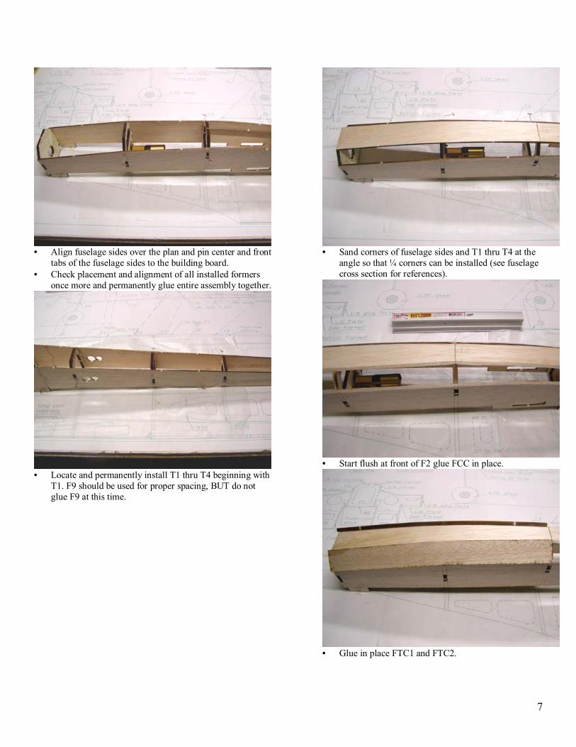
• Glue in place FTC1 and FTC2.

8
• Trim top corners to match cross section on the plan.
• Un-pin fuselage and remove tabs from fuselage sides. • Install and align bottom-sheeting (BS) use F9 while
squaring rear of the fuselage, BUT do not glue F9 at this time.
• Glue BS to all formers (tack glue only at F4) and
fuselage sides. • Sand bottom nose section for ¼ corners (NBC).
• Cut 5-3/4� tri-stock to fit and glue as shown on the
plan and picture. Sand flat to fuselage sides and bottom.

9
• Install and glue NBC in place. Trim flush with side and bottom fuselage sheeting, BUT do not round at this time.
• Place F3, F4 side formers in to their slots on fuselage
sides and pin in place. DO NOT GLUE. • Temporary install LEX under F3 and F4 and pin in place.
Use LEX as a guide draw line where previously installed NBC will need to be trimmed.
• Remove side formers and LEX, trim NBC as marked to
create rounded corner.
• It is a good time to sand corners of the fuselage to
match cross section on the plan.
• Using sharp knife blade remove horizontal stabilizer
slot at the rear of the fuselage.
• Pin fuselage over the plan, it should lay on its front
and rear formers.

10
• Install fuselage side formers F1 � F8. Use wing plate (NO GLUE) to properly position F5, F6 and F7, pin to building board.
• Slide horizontal stabilizer assembly in to the slot.
Temporary install Vertical Fin (VF) assembly and pin in place. Make sure F8 former is flat on building board and well pinned down. Make sure VF sits tight on side F7 and F8 formers (this will set-up correct horizontal stabilizer position).
• Once everything aligned and straight tack glue horizontal
stabilizer to back of F8 former in few places.
• Install wing plate using aluminum wing tube to make
sure all the tube holes are aligned. Glue wing plate to all formers it contacts (do not glue VF to formers or the wing plate).
• Remove VF from Fuselage. Install F9 center former
and side formers. Be sure to push F9 up against horizontal stabilizer. Check alignment and secure assembly with pins.
• Glue horizontal stabilizer permanently to F8, F9 as well as to all parts it contacts.
11
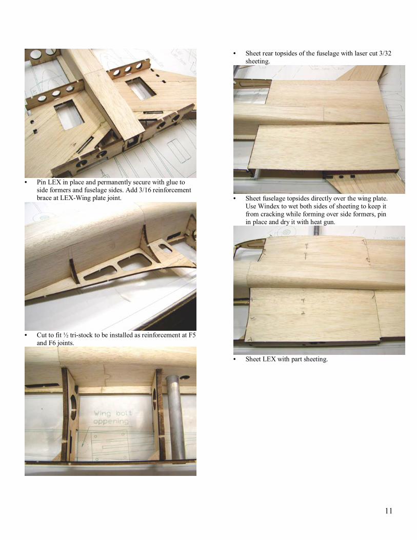
• Pin LEX in place and permanently secure with glue to
side formers and fuselage sides. Add 3/16 reinforcement brace at LEX-Wing plate joint.
• Cut to fit ½ tri-stock to be installed as reinforcement at F5
and F6 joints.
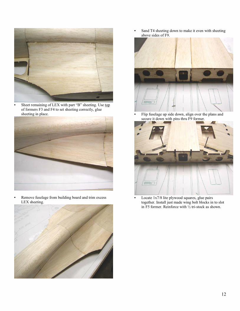
• Sheet rear topsides of the fuselage with laser cut 3/32 sheeting.
• Sheet fuselage topsides directly over the wing plate.
Use Windex to wet both sides of sheeting to keep it from cracking while forming over side formers, pin in place and dry it with heat gun.
• Sheet LEX with part sheeting.
12
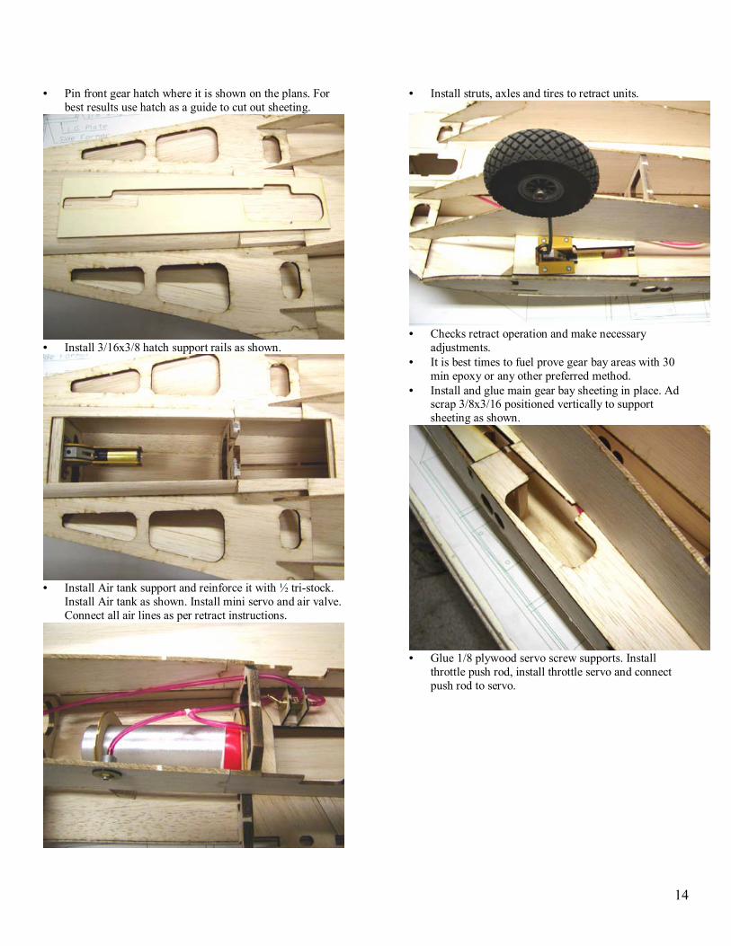
• Sheet remaining of LEX with part �B� sheeting. Use top
of formers F3 and F4 to set sheeting correctly, glue sheeting in place.
• Remove fuselage from building board and trim excess
LEX sheeting.
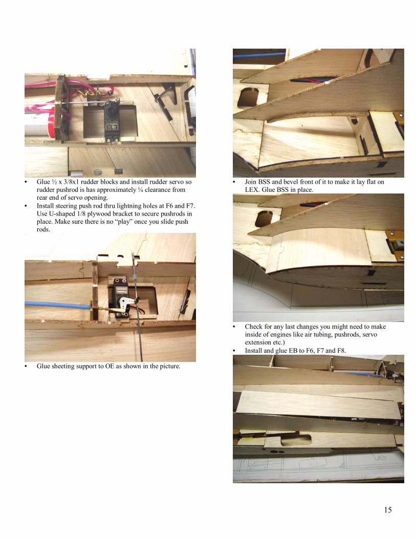
• Sand T4 sheeting down to make it even with sheeting above sides of F9.
• Flip fuselage up side down, align over the plans and
secure it down with pins thru F9 former.
• Locate 1x7/8 lite plywood squares, glue pairs
together. Install just made wing bolt blocks in to slot in F5 former. Reinforce with ½ tri-stock as shown.

13
• Epoxy retracts plates and use clamps while epoxy is
drying. Use scrap 3/32 balsa to prevent clamp damage to upper sheeting.
• Install and glue all bottom parts of the fuselage formers.
• Be sure to align little tab at F8 former install and glue
Inside Engine (IE) sheeting to all contacting parts.
• Install and glue Outside Engine sheeting (OE) as you
did in previous step. Do not glue to LEX at this point.
• Mark pivot point and drop in main retract units
aligning them with marks on retract plates.
14
• Pin front gear hatch where it is shown on the plans. For best results use hatch as a guide to cut out sheeting.
• Install 3/16x3/8 hatch support rails as shown.
• Install Air tank support and reinforce it with ½ tri-stock.
Install Air tank as shown. Install mini servo and air valve. Connect all air lines as per retract instructions.
• Install struts, axles and tires to retract units.
• Checks retract operation and make necessary
adjustments. • It is best times to fuel prove gear bay areas with 30
min epoxy or any other preferred method. • Install and glue main gear bay sheeting in place. Ad
scrap 3/8x3/16 positioned vertically to support sheeting as shown.
• Glue 1/8 plywood servo screw supports. Install
throttle push rod, install throttle servo and connect push rod to servo.
15
• Glue ½ x 3/8x1 rudder blocks and install rudder servo so
rudder pushrod is has approximately ¼ clearance from rear end of servo opening.
• Install steering push rod thru lightning holes at F6 and F7. Use U-shaped 1/8 plywood bracket to secure pushrods in place. Make sure there is no �play� once you slide push rods.
• Glue sheeting support to OE as shown in the picture.
• Join BSS and bevel front of it to make it lay flat on
LEX. Glue BSS in place.
• Check for any last changes you might need to make
inside of engines like air tubing, pushrods, servo extension etc.)
• Install and glue EB to F6, F7 and F8.

16
• Sand F5 bottom to match engine side sheeting. Install EB1 and glue it in.
• Bevel to fit IS so is flat on LEX and side of F5. Glue IS in
place. Use scrap ¼ balsa to fill small opening next to IS.
• Sand EB and engine sheeting to except corner pieces EC.
• Glue EC in place. Round corners as shown on the
plan.
• Install engine mount. Install engine so front of its
drive washer approximately 5-3/4� from the front of the F2 former (use provided ¼ mount extension).

17
• Tack glue scrap 3/32 strips to the back plate of the spinner and then center back plate on F1.
• Install back plate and rest of the spinner on to engine. • With engine installed, glue in place nose top (NT), nose
side (NS) and then nose bottom (NB). • Remove engine from the engine mount and install right
side (NS).
• Sand NT, NS and NB for corner pieces (NBC and NTC).
Trim as needed and glue nose corners in place being careful not to apply too much force while glue dries. Roughly trim corners to shape.
• Mark and cut opening for the engine on the right side
of the fuselage. Be sure to start with smaller opening and enlarging it as needed to fit your engine. Try to make it neat in appearance as well. Install engine once again and use spinners back plate to determent placement of the 1/16 plywood nose ring. Glue ring in place.
• Sand nose section to shape using plans and picture as
a references.

18
• Locate all the parts and assemble tail boom, pin together
and glue. Use medium CA from the inside to make glue joints little easier to trim.
• Remove tail boom from the building board and glue TBS
to sides of TB (see CD for more pictures).
• Join sheeting for TBS, glue sheeting in place. Test fit tail
boom to fuselage and make necessary adjustments.
• Build exhaust cones by placing and gluing one layer
at a time. Use etched marks for alignment. Use thin CA from outside. Ad 1/16 plywood cap (TC) and Sand exhaust cones to shape as shown. It is OK to have cones not perfectly smooth; it will add some realism to the model.
• Install and glue hatch support (HS) to F8. Install and
glue 1/8-balsa hatch rails to inside of servo area.

19
• Trim ABS hatches to fit in place. Mark them as right and
left. Drill two screw holes on each side. Screws should go in to HS and F9 former. Trim 1/8 sheeting to make smooth transition.
• Join bottom fins and test fit to fuselage. Sand LE, bottom
and TE of the fins to rounded shape. Do not glue fins to fuselage until later when covering is done.
• Cut out boom tip pattern from the plan. Use it to
mark 2X2X3 balsa block on both sides. Use jig saw to cut one side first, then pin back just cut off pieces and cut second side.

20
• Tack glue boom tip to tail boom and sand it to final shape as on the plan. It is a good time to slightly round corners of the boom assembly and boom sides.
• Use center marks on sides of F9 and engine humps to
correctly place engine humps. Mark humps position on fuselage.
• Pin exhaust cones to fuselage aligning them at the top of
engine humps and centering them side to side on bottom of F9. Install and pin tail boom and check for alignment by looking at the rear of the plane from about 8 feet.
• Trace exhaust pipes on to engine humps, remove
engine humps and trim edges to make nice transition to fuselage and exhaust cones.
• From ½ tri-stock cut two 6� long pieces, glue them
flat side out to the bottom of 3/32 sheeting centered between F7 and F8. This will be added support for vertical fin installation.
21
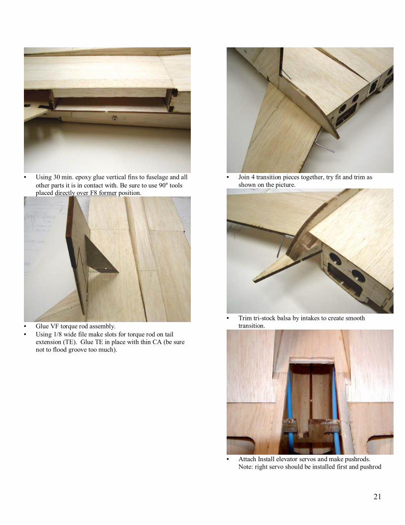
• Using 30 min. epoxy glue vertical fins to fuselage and all
other parts it is in contact with. Be sure to use 90° tools placed directly over F8 former position.
• Glue VF torque rod assembly. • Using 1/8 wide file make slots for torque rod on tail
extension (TE). Glue TE in place with thin CA (be sure not to flood groove too much).
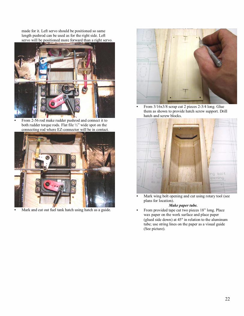
• Join 4 transition pieces together, try fit and trim as
shown on the picture.
• Trim tri-stock balsa by intakes to create smooth
transition.
• Attach Install elevator servos and make pushrods.
Note: right servo should be installed first and pushrod
22
made for it. Left servo should be positioned so same length pushrod can be used as for the right side. Left servo will be positioned more forward than a right servo.
• From 2-56 rod make rudder pushrod and connect it to
both rudder torque rods. Flat file ½� wide spot on the connecting rod where EZ-connector will be in contact.
• Mark and cut out fuel tank hatch using hatch as a guide.
• From 3/16x3/8 scrap cut 2 pieces 2-3/4 long. Glue
them as shown to provide hatch screw support. Drill hatch and screw blocks.
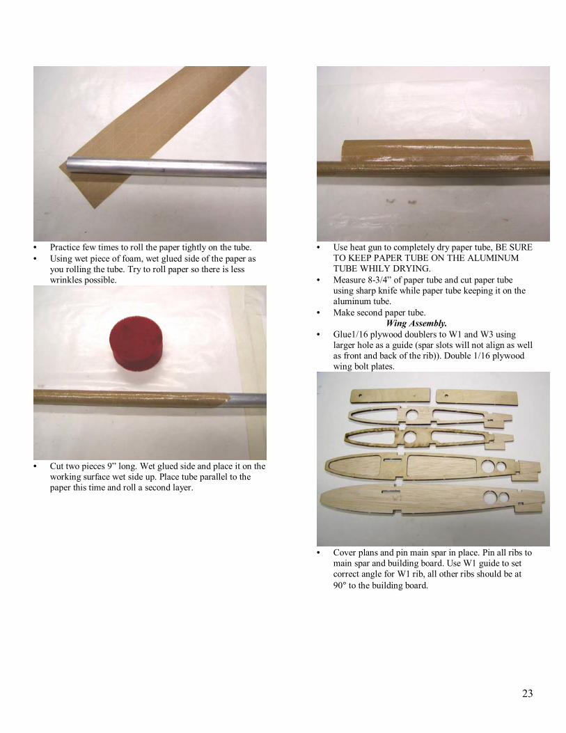
• Mark wing bolt opening and cut using rotary tool (see
plans for location). Make paper tube.
• From provided tape cut two pieces 18� long. Place wax paper on the work surface and place paper (glued side down) at 45° in relation to the aluminum tube; use string lines on the paper as a visual guide (See picture).
23
• Practice few times to roll the paper tightly on the tube. • Using wet piece of foam, wet glued side of the paper as
you rolling the tube. Try to roll paper so there is less wrinkles possible.
• Cut two pieces 9� long. Wet glued side and place it on the
working surface wet side up. Place tube parallel to the paper this time and roll a second layer.
• Use heat gun to completely dry paper tube, BE SURE
TO KEEP PAPER TUBE ON THE ALUMINUM TUBE WHILY DRYING.
• Measure 8-3/4� of paper tube and cut paper tube using sharp knife while paper tube keeping it on the aluminum tube.
• Make second paper tube. Wing Assembly.
• Glue1/16 plywood doublers to W1 and W3 using larger hole as a guide (spar slots will not align as well as front and back of the rib)). Double 1/16 plywood wing bolt plates.
• Cover plans and pin main spar in place. Pin all ribs to
main spar and building board. Use W1 guide to set correct angle for W1 rib, all other ribs should be at 90° to the building board.

24
• Slide guide paper tube on to aluminum tube and place it
thru W1-W3 ribs. Use something to support �free� end of the aluminum tube so it does not lift ribs from the building board.
• Install doubled plywood bolt plate at W1 and W2. Check
all parts for proper alignment and permanently glue together.
• Install and glue top spar to all ribs making sure W1
maintains its set angle.
• Install and glue 1/16 plywood tube sheer web. Install
all 1/16-balsa laser cut sheer web.

25
• Install and glue top and bottom laser cut 1/8x1/4 rear spars. You will need to angle trim bottom spar so it fits against W7 rib.
• Trim and install laser cut wing TE and glue in place.
Install laser cut 1/8-balsa reinforcements at W5 and TE.
• From 1/4x1x36 cut 27�long pieces to make wing LE.
Place it on building board at W7 and center it on W1 rib. Glue LE to all ribs at this time.
• Join 3/32 LE sheeting as shown.
• Bevel front edge of sheeting so it has a good contact
with leading edge. Glue sheeting in place by starting at LE only, then apply glue to all ribs using extended glue tip and then glue sheeting to main spar using long sanding bar to help you hold sheeting down while glue dries.
26
• Align with plans and glue in place WS3 sheeting.
• Install and glue WS2, trim as needed WS1 and glue in
place.
• Trim as needed and glue laser cut rib caps (provided
oversized intentionally).
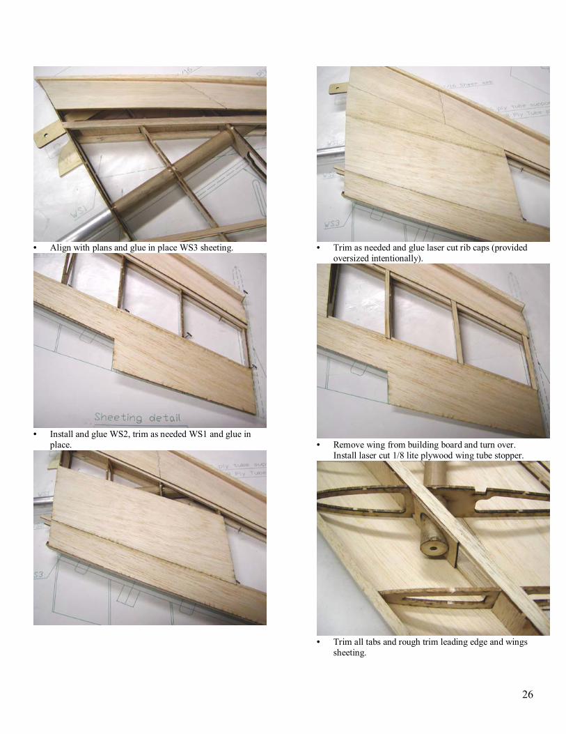
• Remove wing from building board and turn over.
Install laser cut 1/8 lite plywood wing tube stopper.
• Trim all tabs and rough trim leading edge and wings
sheeting.

27
• From 3/8x3/16 leftover cut servo hatch rail, install and glue rail to W2 and W3.
• Place ¼ Wing Jig over the plan of opposite wing and
securely pin down. Place wing on it aligning wing jig and TE of the wing directly above it.
• Bevel TE of the WS3 sheeting (bevel both WS3, see plan
for details). Glue WS3 using opposite side sheeting as a guide.
• Glue in place WS2 aligning it with servo hatch.
• Make and glue LE sheeting in same manner as you
did for opposite side.

28
• Try fit and permanently glue WS1. • Trim as needed and glue laser cut rib caps.
• Remove wing from building board, trim and sand as
needed. Sand wing TE to create airfoil profile matching plans.
• Align center of servos shaft with etched line on the servo hatch, mark position and install 3/8x1/2x3/4 servo blocks as shown. Install servos as shown.
• Glue hatch screw blocks as shown on the picture. Use
hatch as a guide to drill screw holes in to blocks.

29
• Repeat steps for other side wing. • Install wings to fuselage. Drill thru Wing Bolt Plate
(WBP) and tap wing bolt blocks (use 1� 4-20 plastic screws when securing the wing).
Aileron assembly. • Cover plan and pin aileron base over it. • Pin in place and glue aileron laser cut LE making sure
Line and marking �TOP� are facing forward. This line will be used for hinge installation.
• Install all ribs and laser cut horn block.
• Remove aileron from building board and cut hinge
slots in to wing and aileron as shown on the plan.
• Shape leading edge on aileron as shown on the plan. • Build opposite side aileron.
30
• Install servo hatches and connect pushrods to control horns. Bend pushrods as required achieving aileron complete range of motion.
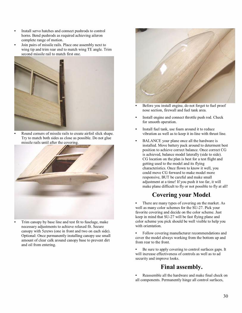
• Join pairs of missile rails. Place one assembly next to wing tip and trim rear end to match wing TE angle. Trim second missile rail to match first one.
• Round corners of missile rails to create airfoil slick shape.
Try to match both sides as close as possible. Do not glue missile rails until after the covering.
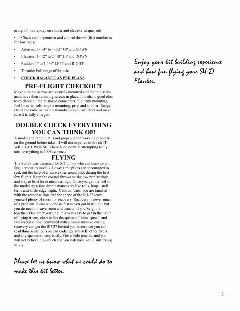
• Trim canopy by base line and test fit to fuselage, make
necessary adjustments to achieve relaxed fit. Secure canopy with 5crews (one in front and two on each side). Optional: Once permanently installing canopy use small amount of clear calk around canopy base to prevent dirt and oil from entering.
• Before you install engine, do not forget to fuel proof
nose section, firewall and fuel tank area.
• Install engine and connect throttle push rod. Check for smooth operation.
• Install fuel tank, use foam around it to reduce vibration as well as to keep it in-line with thrust line.
• BALANCE your plane once all the hardware is installed. Move battery pack around to determent best position to achieve correct balance. Once correct CG is achieved, balance model laterally (side to side). CG location on the plan is best for a test flight and getting used to the model and its flying characteristics. Once flown to know it well, you could move CG forward to make model more responsive, BUT be careful and make small adjustment at a time! If you push it too far, it will make plane difficult to fly or not possible to fly at all!
Covering your Model.
• There are many types of covering on the market. As well as many color schemes for the SU-27. Pick your favorite covering and decide on the color scheme. Just keep in mind that SU-27 will be fast flying plane and color scheme you pick should be well visible to help you with orientation.
• Follow covering manufacturer recommendations and cover the model always working from the bottom up and from rear to the front.
• Be sure to apply covering to control surfaces gaps. It will increase effectiveness of controls as well as to ad security and improve looks.
Final assembly. • Reassemble all the hardware and make final check on all components. Permanently hinge all control surfaces,
31
using 30 min. epoxy on rudder and elevator torque rods.
• Check radio operation and control throws (first number is for low rates)
• Ailerons: 1-1/4� to 1-1/2� UP and DOWN
• Elevator: 1-1/2� to 2-1/8� UP and DOWN
• Rudder: 1� to 1-1/4� LEFT and RIGHT
• Throttle: Full range of throttle.
• CHECK BALANCE AS PER PLANS.
PRE-FLIGHT CHECKOUT Make sure the servos are securely mounted and that the servo arms have their retaining screws in place. It is also a good idea to re-check all the push-rod connectors, fuel tank mounting, fuel lines, wheels; engine mounting, prop and spinner. Range check the radio as per the manufacturers instructors and make sure it is fully charged.
DOUBLE CHECK EVERYTHING YOU CAN THINK OF!
A model and radio that is not prepared and working properly on the ground before take off will not improve in the air IT WILL GET WORSE! There is no point in attempting to fly until everything is 100% correct.
FLYING The SU-27 was designed for R/C pilots who can keep up with fast, aerobatics models. Lower time pilots are encouraged to seek out the help of a more experienced pilot during the first few flights. Keep the control throws on the low rate settings and stay at least three mistakes high. Once you get the feel for the model try a few simple maneuvers like rolls, loops, stall turns and knife-edge flight. Caution. Until you are familial with the response time and the shape of the SU-27 leave yourself plenty of room for recovery. Recovery is never much of a problem, it can be done as fast as you got in trouble, but you do need to leave room and time until you�ve got it together. One other warning, it is very easy to get in the habit of frying it very close in the deception of �slow speed� and fast response time combined with a minor mistake during recovery can get the SU-27 behind you faster than you can read thins sentence You can endanger yourself, other flyers and any spectators very easily. Get a little practice and you will not believe how much fun you will have while still frying safely.
Please let us know what we could do to make this kit better.
Enjoy your kit building experience and have fun flying your SU-27 Flanker.