Embed Size (px)
Citation preview
A.Kamojang Geothermal Field
Imam Raharjo
2010

Typical Andesitic geothermal systemComponents:- heat source- reservoir- cap rock- recharge support
Surface expression :• fumaroles• geysers, hotsprings, etc• hot pool (liquid)• mud pool
• hydrothermal mineral deposits, e.g sinter (SiO2), travertine (CaCO3)• Cold gas seep (CO2), (=kaipohan)•- etc

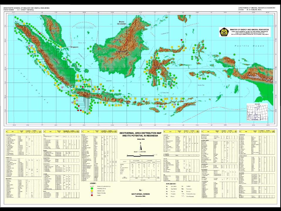
Vocanoes in Indonesia(www.volcano.si.edu)
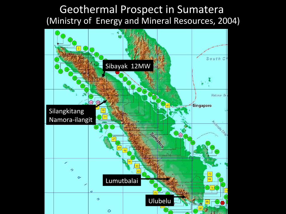
Geothermal Prospect in Sumatera (Ministry of Energy and Mineral Resources, 2004)
Sibayak 12MW
SilangkitangNamora-ilangit
Lumutbalai
Ulubelu
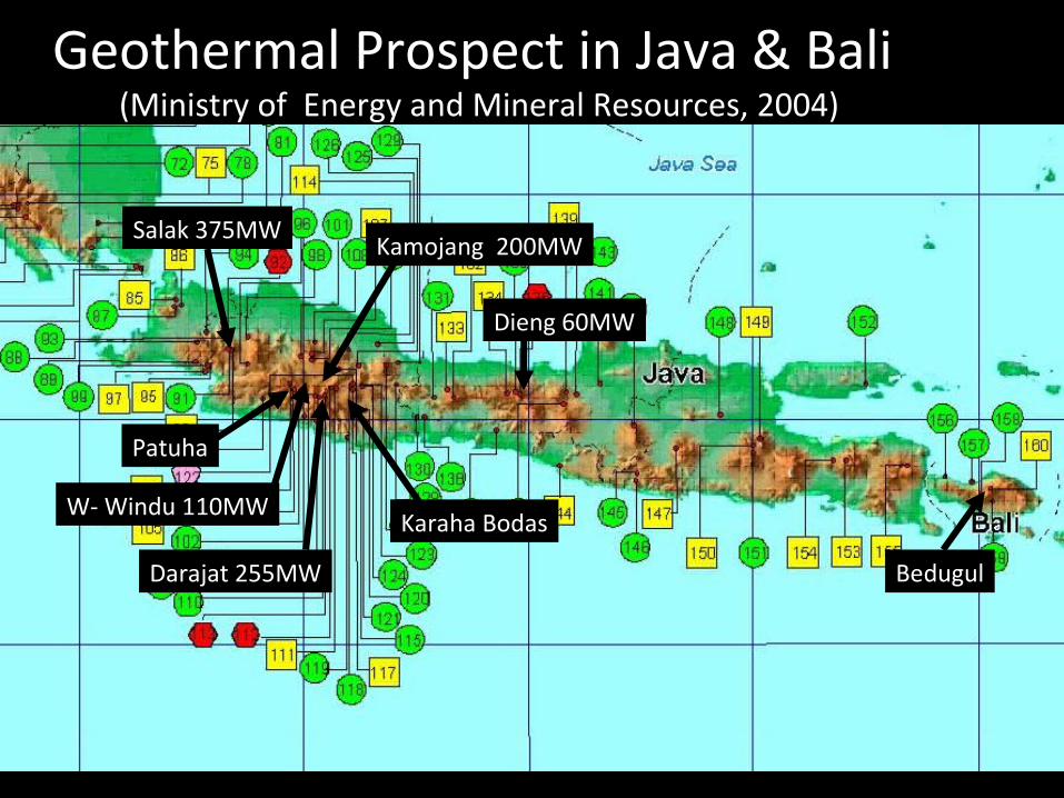
Salak 375MW
W- Windu 110MW
Darajat 255MW
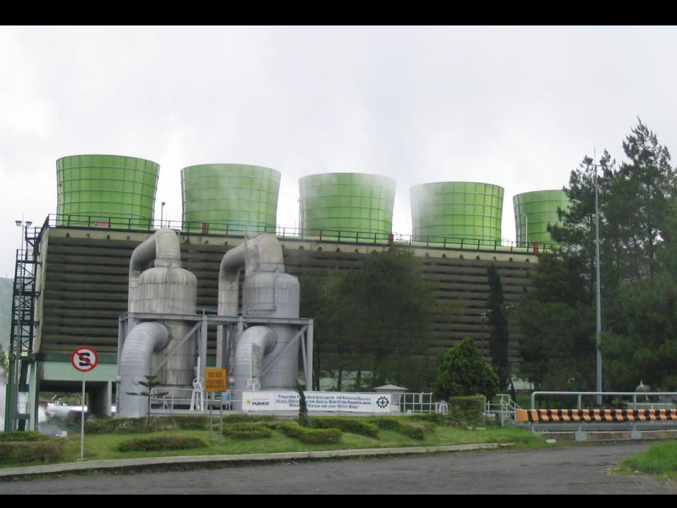
Kamojang 200MW
Dieng 60MW
Geothermal Prospect in Java & Bali (Ministry of Energy and Mineral Resources, 2004)
Patuha
Karaha Bodas
Bedugul
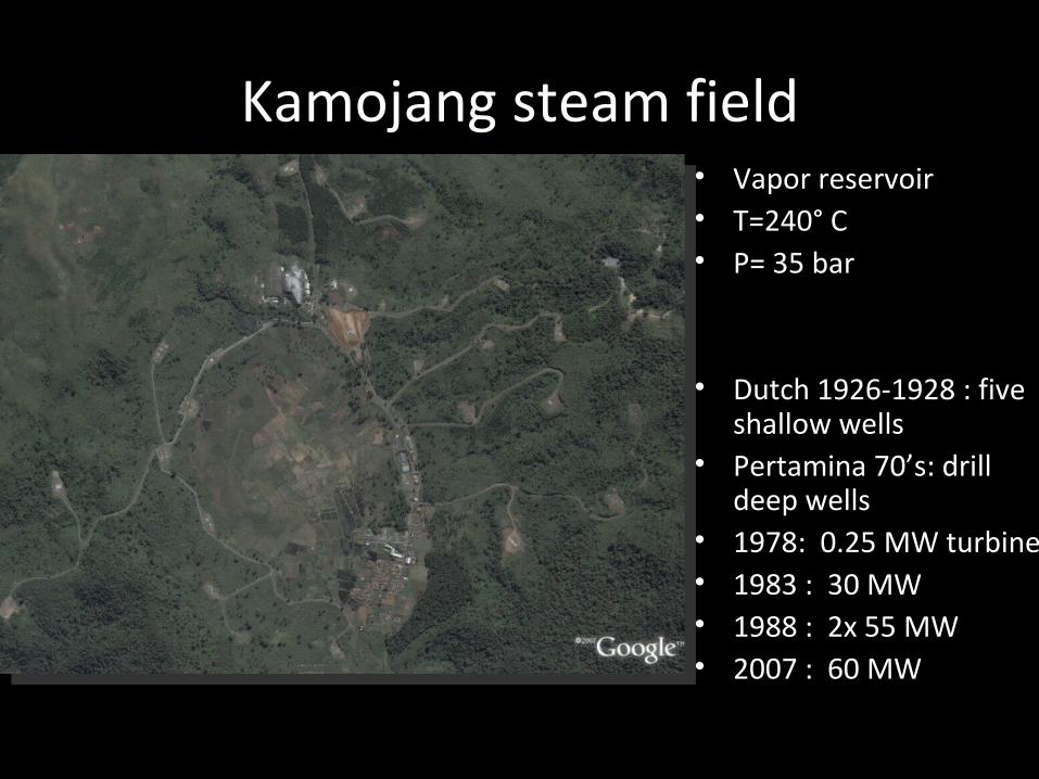
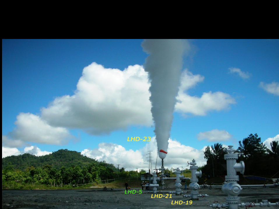
Kamojang steam field• Vapor reservoir• T=240° C• P= 35 bar
• Dutch 1926-1928 : five shallow wells
• Pertamina 70’s: drill deep wells
• 1978: 0.25 MW turbine• 1983 : 30 MW• 1988 : 2x 55 MW• 2007 : 60 MW
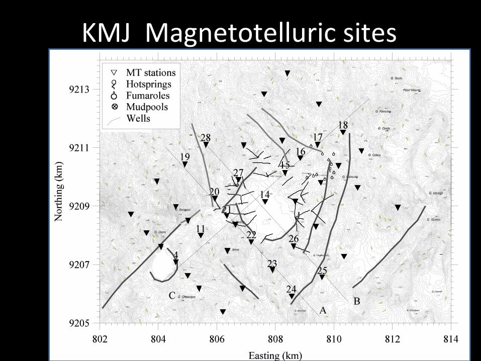
KMJ Magnetotelluric sites
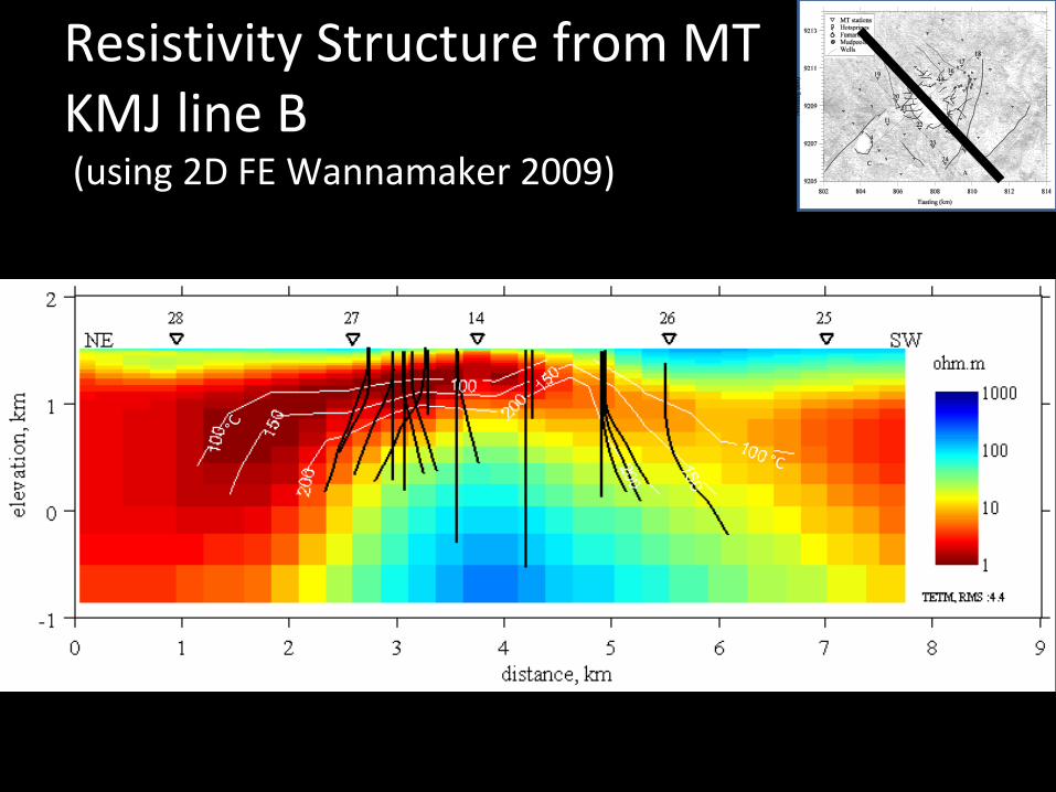
Resistivity Structure from MTKMJ line B (using 2D FE Wannamaker 2009)
°C
°C
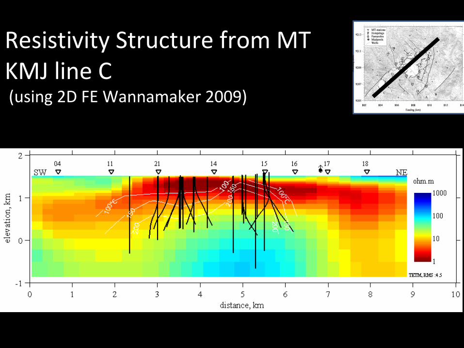
Resistivity Structure from MTKMJ line C (using 2D FE Wannamaker 2009)
°C
°C
Summary : MT KMJ
• The conductor (< 10 ohm.m) is in agreement with smectite zone, having the temperature of up to 150 °C
• The conductor is thin over the reservoir. It thickens and deepens to the side of the reservoir
• The underlying slightly resistive zone (20-80 ohm.m) is also in agreement with the propylitic zone, up to 240 °C
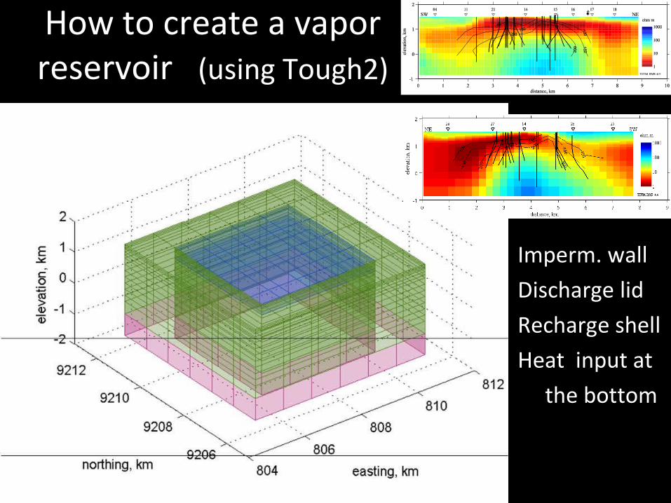
How to create a vapor reservoir (using Tough2)
• Imperm. wall• Discharge lid• Recharge shell• Heat input at • the bottom
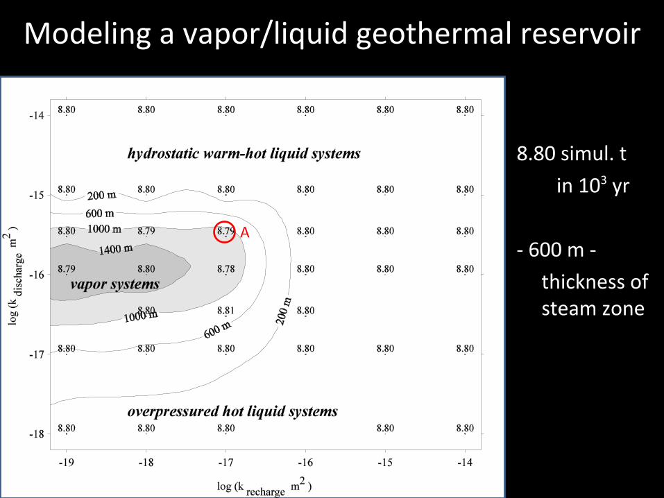
Modeling a vapor/liquid geothermal reservoir
8.80 simul. t
in 103 yr
- 600 m -
thickness of steam zone
A

Temperature evolution from model A
b a c d e f g h i
j k l m
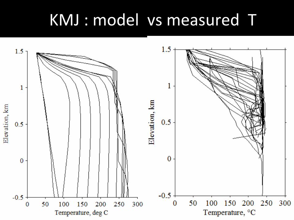
KMJ : model vs measured Tj k l m
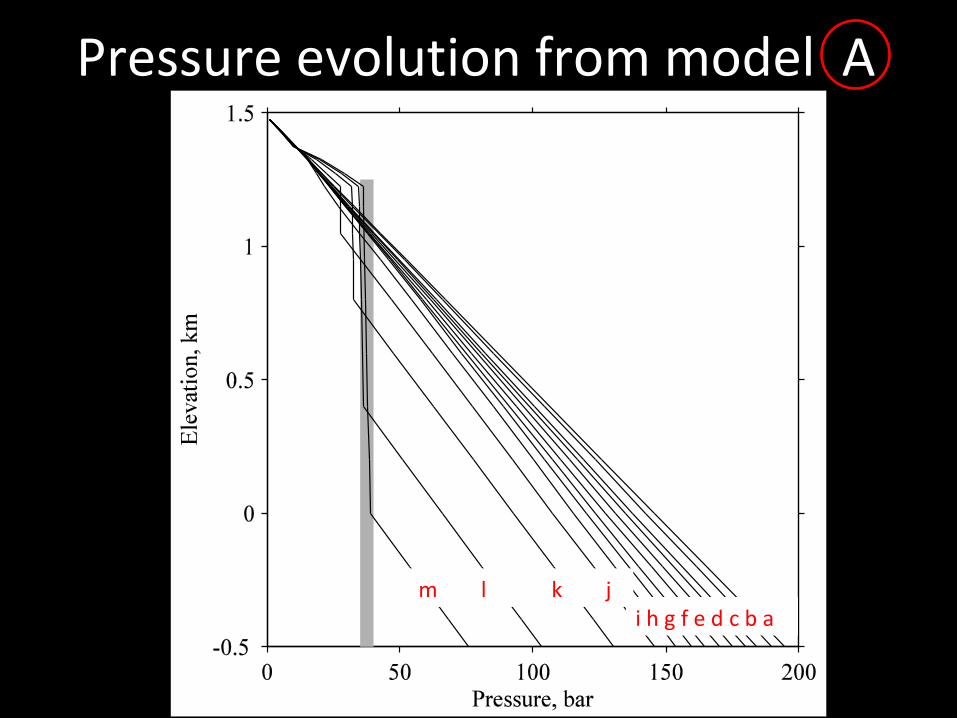
Pressure evolution from model A
i h g f e d c b am l k j

KMJ : model vs measured P
(abs)
8.8 kyears
8.6 kyears

Summary : Vapor reservoir in a volcanic environment
• impermeable wall (k ~1E-18 m2)• slightly impermeable recharge (k ~1E-17 m2)• moderately impermeable discharge(k ~1E-16 m2)• high heatflow to the bottom of the reservoir, 8
MW/km2, short lived impulses from intrusions• eight thousand years to develop the liquid system,
800 hundred years to convert the liquid into steam
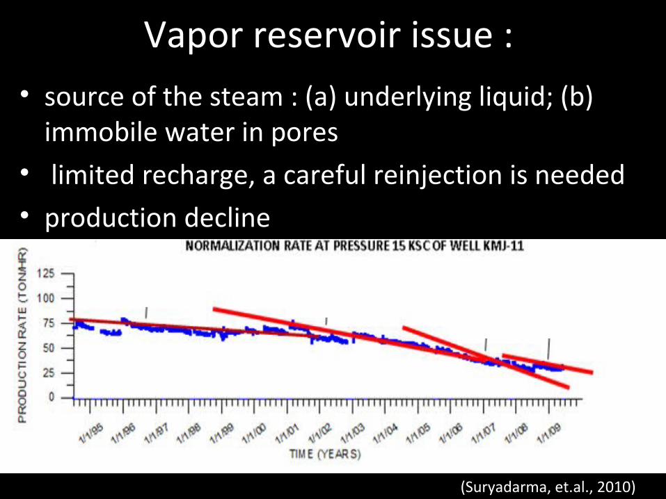
Vapor reservoir issue : • source of the steam : (a) underlying liquid; (b)
immobile water in pores • limited recharge, a careful reinjection is needed• production decline
(Suryadarma, et.al., 2010)
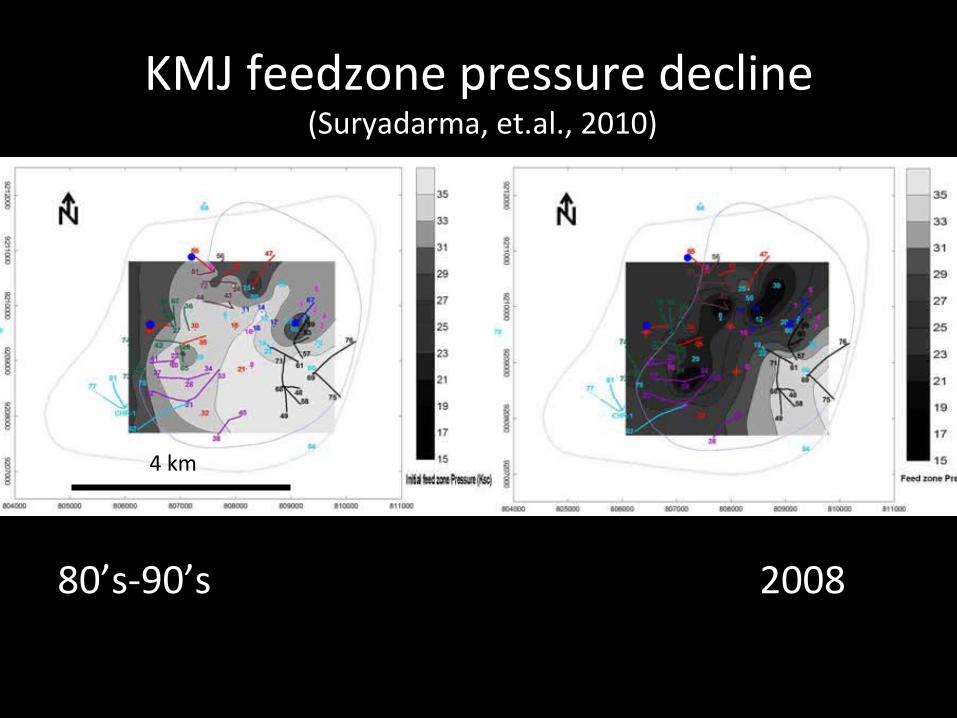
KMJ feedzone pressure decline (Suryadarma, et.al., 2010)
80’s-90’s 2008
4 km
B. Resource assessment (exploration stage)
• prospect size : from geophysical & geological studies
• temperature, from geochemical study or downhole measurement
• predict the system : vapor? liquid ?• volumetric heat stored calculation
(MonteCarlo Simulation)
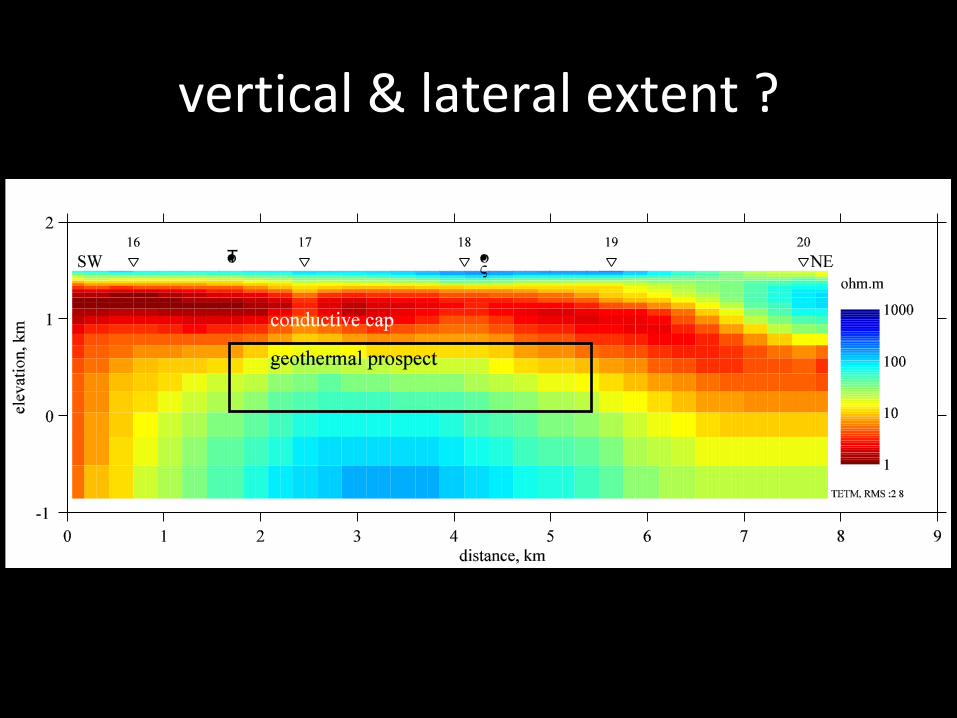
vertical & lateral extent ?
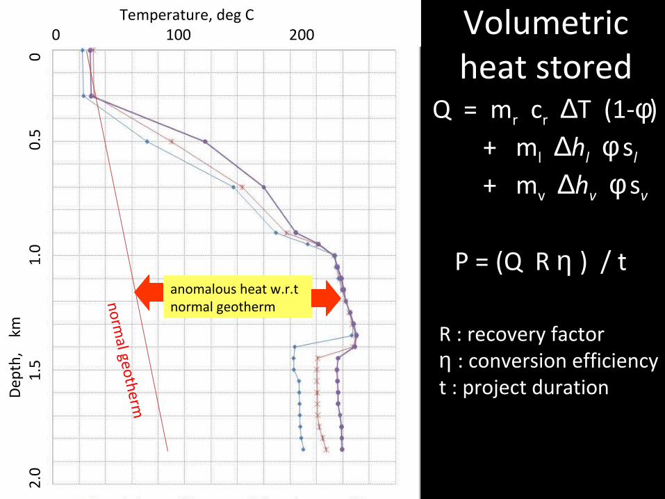
Volumetric heat stored
anomalous heat
Q = mr cr ∆T (1-φ) + ml ∆hl φ sl + mv ∆hv φ sv
P = (Q R η ) / t
R : recovery factorη : conversion efficiencyt : project duration
normal geotherm
anomalous heat w.r.t normal geotherm
Temperature, deg C 0 100 200
D
epth
, k
m 2
.0
1.5
1.0
0.5
0

Exercise example
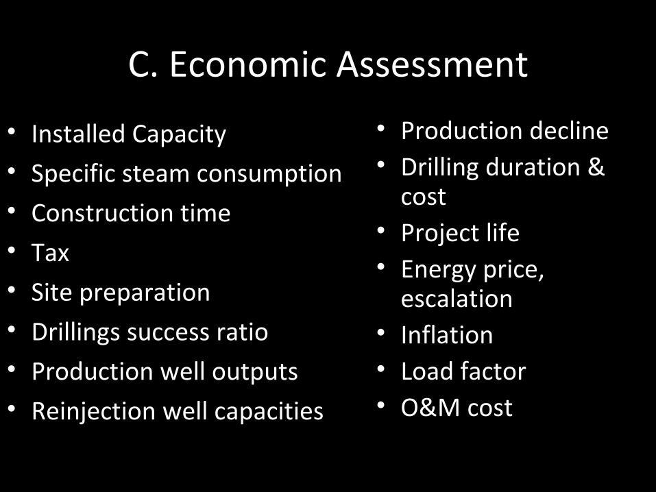
C. Economic Assessment
• Installed Capacity• Specific steam consumption• Construction time• Tax• Site preparation• Drillings success ratio• Production well outputs• Reinjection well capacities
• Production decline• Drilling duration &
cost• Project life • Energy price,
escalation• Inflation• Load factor• O&M cost
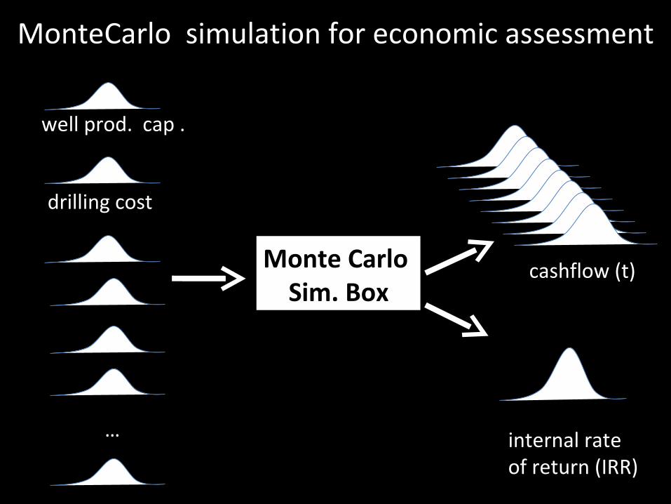
MonteCarlo simulation for economic assessment
Monte Carlo Sim. Box
cashflow (t)
internal rate of return (IRR)
well prod. cap .
drilling cost
…

Exercise example
Thank you

Thank you
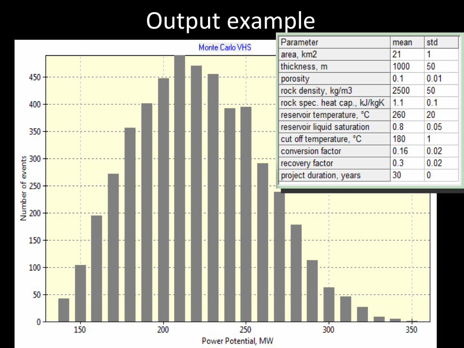
Output example