Embed Size (px)
Citation preview
Title page
Alcatel-Lucent 9768
Compact Metro Radio Outdoor
Site Preparation
3MN-01582-0001-RJZZA
Issue 0.03 | November 2015
Alcatel-Lucent – Proprietary
Use pursuant to applicable agreements
Use pursuant to applicable agreements
DRA
FT
DRA
FT
Legal notice
Legal notice
Alcatel, Lucent, Alcatel-Lucent and the Alcatel-Lucent logo are trademarks of Alcatel-Lucent. All other trademarks are the property of their respective
owners.
The information presented is subject to change without notice. Alcatel-Lucent assumes no responsibility for inaccuracies contained herein.
Copyright © 2015 Alcatel-Lucent. All rights reserved.
Contains proprietary/trade secret information which is the property of Alcatel-Lucent and must not be made available to, or copied or used by anyone outside
Alcatel-Lucent without its written authorization.
Not to be used or disclosed except in accordance with applicable agreements.
Use pursuant to applicable agreements
Alcatel-Lucent – Proprietary
Use pursuant to applicable agreements
DRA
FT
DRA
FT
Contents
About this document
Purpose ............................................................................................................................................................................................. xixi
Intended audience ......................................................................................................................................................................... xixi
Supported systems ........................................................................................................................................................................ xixi
How to use this document ......................................................................................................................................................... xixi
Safety information ...................................................................................................................................................................... xiixii
Prerequisites .................................................................................................................................................................................. xiixii
Site preparation checklists ....................................................................................................................................................... xiixii
Conventions used ........................................................................................................................................................................ xiixii
Related information ................................................................................................................................................................... xivxiv
Document support ...................................................................................................................................................................... xivxiv
Technical support ....................................................................................................................................................................... xivxiv
How to order .................................................................................................................................................................................. xvxv
How to comment .......................................................................................................................................................................... xvxv
1 Safety statements
Overview ...................................................................................................................................................................................... 1-11-1
Structure of safety statements ............................................................................................................................................... 1-21-2
General safety considerations ............................................................................................................................................... 1-31-3
Safety ........................................................................................................................................................................................... 1-41-4
Safety - specific hazards ......................................................................................................................................................... 1-51-5
Product safety ............................................................................................................................................................................. 1-91-9
2 Hardware architecture and functionality
Overview ...................................................................................................................................................................................... 2-12-1
....................................................................................................................................................................................................................................
Alcatel-Lucent 9768 CMRO
3MN-01582-0001-RJZZA
Issue 0.03 November 2015
Alcatel-Lucent – Proprietary
Use pursuant to applicable agreements
iii
DRA
FT
DRA
FT
Functional description ............................................................................................................................................................. 2-12-1
Physical description ................................................................................................................................................................. 2-32-3
7705 SAR-O hardware overview and ancillary ............................................................................................................. 2-92-9
Supported installation options ........................................................................................................................................... 2-152-15
Hardware and ancillary items ............................................................................................................................................ 2-252-25
3 Site selection
Overview ...................................................................................................................................................................................... 3-13-1
Environmental and mechanical specifications ............................................................................................................... 3-23-2
Spectrum analysis of RF neighborhood ............................................................................................................................ 3-33-3
Site requirements ...................................................................................................................................................................... 3-43-4
Site power requirements (AC) ............................................................................................................................................. 3-53-5
Site power requirements (DC) ............................................................................................................................................. 3-73-7
9768 CMRO power requirements ....................................................................................................................................... 3-93-9
Grounding and lightning protection ................................................................................................................................ 3-103-10
9768 CMRO product grounding ....................................................................................................................................... 3-113-11
General antenna cable requirements ................................................................................................................................ 3-133-13
Site requirements for link to baseband processing unit ............................................................................................ 3-143-14
Site requirements for a wall mount installation ........................................................................................................... 3-143-14
Site requirements for a pole mount installation ........................................................................................................... 3-143-14
Site requirements for strand-mount installation .......................................................................................................... 3-153-15
A Site survey checklists
Overview ..................................................................................................................................................................................... A-1A-1
SS-1 Venue survey checklist ................................................................................................................................................ A-1A-1
SS-2 Site survey general checklist .................................................................................................................................... A-3A-3
SS-3 Site survey access checklist ...................................................................................................................................... A-6A-6
SS-4 Site survey conclusion ................................................................................................................................................ A-7A-7
Contents
....................................................................................................................................................................................................................................
....................................................................................................................................................................................................................................
iv Alcatel-Lucent – Proprietary
Use pursuant to applicable agreements
Alcatel-Lucent 9768 CMRO
3MN-01582-0001-RJZZA
Issue 0.03 November 2015
DRA
FT
DRA
FT
B Site preparation checklists
Overview ..................................................................................................................................................................................... B-1B-1
SP-1 Site preparation general checklist ........................................................................................................................... B-2B-2
SP-2 Site preparation power source checklist ............................................................................................................... B-3B-3
SP-3 Site preparation grounding checklist ...................................................................................................................... B-4B-4
SP-4 Site preparation RF antenna checklist ................................................................................................................... B-5B-5
SP-5 Site preparation GPS antenna checklist ................................................................................................................ B-6B-6
Site preparation punch list sheet ......................................................................................................................................... B-8B-8
Site preparation punchlist sheet .......................................................................................................................................... B-9B-9
C Product conformance statements
Overview ..................................................................................................................................................................................... C-1C-1
United States compliance
Introduction ................................................................................................................................................................................ C-2C-2
Federal Communications Commission ............................................................................................................................ C-2C-2
Product safety conformance statements ........................................................................................................................... C-4C-4
Antenna exposure statements .............................................................................................................................................. C-5C-5
FDA/IEC optical transmitter product compliance statements ................................................................................. C-5C-5
Eco-environmental statements ............................................................................................................................................ C-6C-6
Canadian compliance
Introduction ................................................................................................................................................................................ C-8C-8
Industry Canada ........................................................................................................................................................................ C-8C-8
Product safety and exposure ................................................................................................................................................ C-8C-8
Antenna exposure statements .............................................................................................................................................. C-9C-9
IEC optical transmitter product compliance statements .......................................................................................... C-10C-10
Eco-environmental statements .......................................................................................................................................... C-11C-11
Contents
....................................................................................................................................................................................................................................
....................................................................................................................................................................................................................................
Alcatel-Lucent 9768 CMRO
3MN-01582-0001-RJZZA
Issue 0.03 November 2015
Alcatel-Lucent – Proprietary
Use pursuant to applicable agreements
v
DRA
FT
DRA
FT
D Related information
Overview ..................................................................................................................................................................................... D-1D-1
9768 CMRO documentation ................................................................................................................................................ D-1D-1
7705 SAR-O documentation ............................................................................................................................................... D-2D-2
LTE End-to-End Solution and LTE RAN documentation ........................................................................................ D-3D-3
Surge, Grounding, and Lightning documentation ........................................................................................................ D-5D-5
Glossary
Index
Contents
....................................................................................................................................................................................................................................
....................................................................................................................................................................................................................................
vi Alcatel-Lucent – Proprietary
Use pursuant to applicable agreements
Alcatel-Lucent 9768 CMRO
3MN-01582-0001-RJZZA
Issue 0.03 November 2015
DRA
FT
DRA
FT
List of tables
1 Terminology ................................................................................................................................................................... xixi
2-1 9768 CMRO ................................................................................................................................................................ 2-42-4
2-2 Certifications and standards ................................................................................................................................... 2-52-5
2-3 Environmental parameters ...................................................................................................................................... 2-52-5
2-4 7705 SAR-O dimensions ...................................................................................................................................... 2-112-11
2-5 Single mode dual LC to LC ................................................................................................................................. 2-122-12
2-6 Single mode dual LC to FullAXS ..................................................................................................................... 2-132-13
2-7 Kit SAR-O - For channels 1471-1511 ............................................................................................................. 2-142-14
2-8 Kit SAR-O - For channels 1551-1591 ............................................................................................................. 2-142-14
2-9 SFP code for the fourth 7705 SAR-O connector ......................................................................................... 2-142-14
2-10 FULLAXS fiber field install kit ........................................................................................................................ 2-152-15
2-11 Pole-mount installation ......................................................................................................................................... 2-262-26
2-12 Wall-mount installation ......................................................................................................................................... 2-262-26
2-13 Pair-mount installation on a pole ....................................................................................................................... 2-262-26
2-14 Pair-mount installation on a wall ....................................................................................................................... 2-272-27
2-15 Strand-mount installation kit ............................................................................................................................... 2-272-27
3-1 Power materials .......................................................................................................................................................... 3-93-9
3-2 Grounding materials ............................................................................................................................................... 3-113-11
D-1 Related Information - 9768 CMRO ................................................................................................................... D-1D-1
D-2 Related information - 7705 SAR-O ................................................................................................................... D-2D-2
D-3 Related Information - LTE RAN and E2E LTE Solution .......................................................................... D-3D-3
D-4 Related Information - Grounding, Lightning, and Surge ........................................................................... D-5D-5
....................................................................................................................................................................................................................................
Alcatel-Lucent 9768 CMRO
3MN-01582-0001-RJZZA
Issue 0.03 November 2015
Alcatel-Lucent – Proprietary
Use pursuant to applicable agreements
vii
DRA
FT
DRA
FT

List of tables
....................................................................................................................................................................................................................................
....................................................................................................................................................................................................................................
viii Alcatel-Lucent – Proprietary
Use pursuant to applicable agreements
Alcatel-Lucent 9768 CMRO
3MN-01582-0001-RJZZA
Issue 0.03 November 2015
DRA
FT
DRA
FT
List of figures
2-1 Alcatel-Lucent 9768 CMRO ................................................................................................................................. 2-32-3
2-2 Alcatel-Lucent 9768 CMRO connection interfaces ...................................................................................... 2-62-6
2-3 Alcatel-Lucent 7705 Service Aggregation Router-Optical ...................................................................... 2-102-10
2-4 4-Wavelength CWDM Dual-Fiber models .................................................................................................... 2-112-11
2-5 9768 CMRO pole and wall-mount installation ............................................................................................ 2-162-16
2-6 Four 9768 CMROs served by a single mode dual fiber ............................................................................ 2-172-17
2-7 Six 9768 CMROs served by two single mode dual fibers with different wavelengths ................. 2-182-18
2-8 Six 9768 CMROs served by two single mode dual fibers with same wavelength .......................... 2-182-18
2-9 Six 9768 CMROs served by a single mode dual fiber ............................................................................. 2-192-19
2-10 9768 CMRO daisy chaining installation example ...................................................................................... 2-232-23
2-11 Two 9768 CMROs pair-mounted on a pole ................................................................................................... 2-242-24
2-12 Two 9768 CMROs pair-mounted on a wall ................................................................................................... 2-242-24
....................................................................................................................................................................................................................................
Alcatel-Lucent 9768 CMRO
3MN-01582-0001-RJZZA
Issue 0.03 November 2015
Alcatel-Lucent – Proprietary
Use pursuant to applicable agreements
ix
DRA
FT
DRA
FT
List of figures
....................................................................................................................................................................................................................................
....................................................................................................................................................................................................................................
x Alcatel-Lucent – Proprietary
Use pursuant to applicable agreements
Alcatel-Lucent 9768 CMRO
3MN-01582-0001-RJZZA
Issue 0.03 November 2015
DRA
FT
DRA
FT
About this documentAbout this document
Purpose
This document covers the basic site preparation guidelines that should be used to plan an
Alcatel-Lucent 9768 Compact Metro Radio Outdoor site. Specific tasks are outlined that
should be completed at the job site before an installation can begin.
Intended audience
The audience for this document is Site Preparation personnel relating to the
Alcatel-Lucent 9768 Compact Metro Radio Outdoor (9768 CMRO).
Supported systems
This document applies to the following Alcatel-Lucent 9768 Compact Metro Radio
Outdoor models:
• Alcatel-Lucent 9768 Compact Metro Radio Outdoor B66 (AWS1-3) 2x5W v2
How to use this document
Start with the first chapter and work through the manual to the end. Prior to installing the
product, the installer should be familiar with the safety precautions, warnings, and
product conformance statements.
Listed are terminology and naming conventions that may appear in the 9768 CMRO
documentation.
Table 1 Terminology
The full product name, Alcatel-Lucent 9768 Compact Metro Radio Outdoor B66 (AWS1-3)
2x5W v2, is also referred to as:
• Alcatel-Lucent 9768 CMRO
• 9768 CMRO
...................................................................................................................................................................................................................................
Alcatel-Lucent 9768 CMRO
3MN-01582-0001-RJZZA
Issue 0.03 November 2015
Alcatel-Lucent – Proprietary
Use pursuant to applicable agreements
xi
DRA
FT
DRA
FT
Table 1 Terminology (continued)
The full product name, Alcatel-Lucent 7705 Service Aggregation Router-Optical (SAR-O), is
also referred to as:
• Alcatel-Lucent 7705 SAR-O
• 7705 SAR-O
The full product name, Alcatel-Lucent 5620 Service Aware Manager (SAM), is also referred to
as:
• Alcatel-Lucent 5620 SAM
• 5620 SAM
The terms eNodeB Network Element Manager (NEM), eNodeB NEM, and NEM are used to
describe the eNodeB local maintenance applications.
Safety information
For your safety, this document contains safety statements. Safety statements are given at
points where risks of damage to personnel, equipment, and operation may exist. Failure to
follow the directions in a safety statement may result in serious consequences.
Prerequisites
None
Site preparation checklists
All site preparation activities, as well as adherence to the guidelines, should be verified
prior to the installation of the cell site equipment.
Various checklists and punchlist sheets have been provided in Appendix A of this
document to aid customers and Alcatel-Lucent personnel during a base station site
Method of Procedure (MOP) walk-through prior to the equipment installation.
Utilization of the checklists helps ensure a quality installation and provides a base station
site history file for later reference. The punchlist sheets are used to track completion of
any outstanding site preparation items, and to aid in the project management of
installation resources.
Conventions used
The following typographical conventions are used in this manual:
Appearance Description
emphasis Text that is emphasized
About this document
....................................................................................................................................................................................................................................
....................................................................................................................................................................................................................................
xii Alcatel-Lucent – Proprietary
Use pursuant to applicable agreements
Alcatel-Lucent 9768 CMRO
3MN-01582-0001-RJZZA
Issue 0.03 November 2015
DRA
FT
DRA
FT
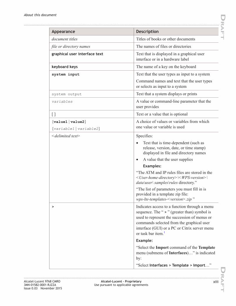
Appearance Description
document titles Titles of books or other documents
file or directory names The names of files or directories
graphical user interface text Text that is displayed in a graphical user
interface or in a hardware label
keyboard keys The name of a key on the keyboard
system input Text that the user types as input to a system
Command names and text that the user types
or selects as input to a system
system output Text that a system displays or prints
variables A value or command-line parameter that the
user provides
[ ] Text or a value that is optional
{value1 | value2}
{variable1 | variable2}
A choice of values or variables from which
one value or variable is used
<delimited text> Specifies:
• Text that is time-dependent (such as
release, version, date, or time stamp)
displayed in file and directory names
• A value that the user supplies
Examples:
“The ATM and IP rules files are stored in the
<User-home-directory>\<WPS-version>\
data\user\ samples\rules directory.”
“The list of parameters you must fill in is
provided in a template zip file:
wps-lte-templates-<version>.zip ”
> Indicates access to a function through a menu
sequence. The “ > ” (greater than) symbol is
used to represent the succession of menus or
commands selected from the graphical user
interface (GUI) or a PC or Citrix server menu
or task bar item.1
Example:
“Select the Import command of the Template
menu (submenu of Interfaces)…” is indicated
by:
“Select Interfaces > Template > Import…”
About this document
....................................................................................................................................................................................................................................
....................................................................................................................................................................................................................................
Alcatel-Lucent 9768 CMRO
3MN-01582-0001-RJZZA
Issue 0.03 November 2015
Alcatel-Lucent – Proprietary
Use pursuant to applicable agreements
xiii
DRA
FT
DRA
FT
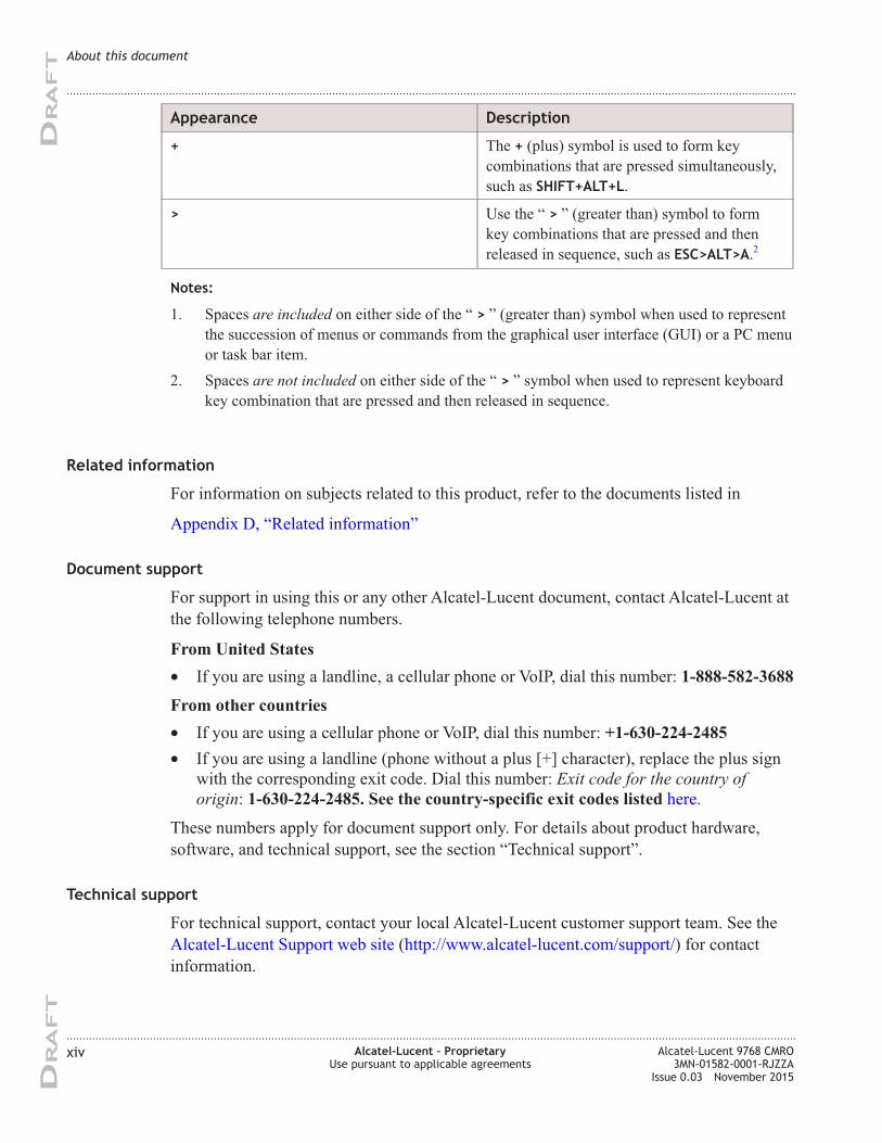
Appearance Description
+ The + (plus) symbol is used to form key
combinations that are pressed simultaneously,
such as SHIFT+ALT+L.
> Use the “ > ” (greater than) symbol to form
key combinations that are pressed and then
released in sequence, such as ESC>ALT>A.2
Notes:
1. Spaces are included on either side of the “ > ” (greater than) symbol when used to represent
the succession of menus or commands from the graphical user interface (GUI) or a PC menu
or task bar item.
2. Spaces are not included on either side of the “ > ” symbol when used to represent keyboard
key combination that are pressed and then released in sequence.
Related information
For information on subjects related to this product, refer to the documents listed in
Appendix D, “Related information”
Document support
For support in using this or any other Alcatel-Lucent document, contact Alcatel-Lucent at
the following telephone numbers.
From United States
• If you are using a landline, a cellular phone or VoIP, dial this number: 1-888-582-3688
From other countries
• If you are using a cellular phone or VoIP, dial this number: +1-630-224-2485
• If you are using a landline (phone without a plus [+] character), replace the plus sign
with the corresponding exit code. Dial this number: Exit code for the country of
origin: 1-630-224-2485. See the country-specific exit codes listed here.
These numbers apply for document support only. For details about product hardware,
software, and technical support, see the section “Technical support”.
Technical support
For technical support, contact your local Alcatel-Lucent customer support team. See the
Alcatel-Lucent Support web site (http://www.alcatel-lucent.com/support/) for contact
information.
About this document
....................................................................................................................................................................................................................................
....................................................................................................................................................................................................................................
xiv Alcatel-Lucent – Proprietary
Use pursuant to applicable agreements
Alcatel-Lucent 9768 CMRO
3MN-01582-0001-RJZZA
Issue 0.03 November 2015
DRA
FT
DRA
FT
How to order
To order Alcatel-Lucent documents, contact your local sales representative or use Online
Customer Support (OLCS) (http://support.alcatel-lucent.com).
How to comment
Note to reviewers: The following "How to comment" text will appear in the final
document when it is published. However, the feedback method described below is for use
only on final documents. Please send your review comments to the author using the
process you were given when you received this draft document.
To comment on this document, go to the Online Comment Form (http://infodoc.alcatel-
lucent.com/comments/) or e-mail your comments to the Comments Hotline
About this document
....................................................................................................................................................................................................................................
....................................................................................................................................................................................................................................
Alcatel-Lucent 9768 CMRO
3MN-01582-0001-RJZZA
Issue 0.03 November 2015
Alcatel-Lucent – Proprietary
Use pursuant to applicable agreements
xv
DRA
FT
DRA
FT
About this document
....................................................................................................................................................................................................................................
....................................................................................................................................................................................................................................
xvi Alcatel-Lucent – Proprietary
Use pursuant to applicable agreements
Alcatel-Lucent 9768 CMRO
3MN-01582-0001-RJZZA
Issue 0.03 November 2015
DRA
FT
DRA
FT
1 1Safety statements
Overview
Purpose
This chapter provides general information on the structure of safety instructions and
summarizes general safety requirements.
General safety and residual risk
The equipment has been developed in line with state-of-the-art technology and conforms
with current national and international safety requirements.
The equipment is considered safe during normal operation when safe working practices
are complied with. However, hazards may arise if procedures are not followed correctly
or safe working practices are not complied with.
Contents
Structure of safety statements 1-2
General safety considerations 1-3
Safety 1-4
Safety - specific hazards 1-5
Product safety 1-9
...................................................................................................................................................................................................................................
Alcatel-Lucent 9768 CMRO
3MN-01582-0001-RJZZA
Issue 0.03 November 2015
Alcatel-Lucent – Proprietary
Use pursuant to applicable agreements
1-1
DRA
FT
DRA
FT
Structure of safety statements
Overview
This topic describes the components of safety statements that appear in this document.
General structure
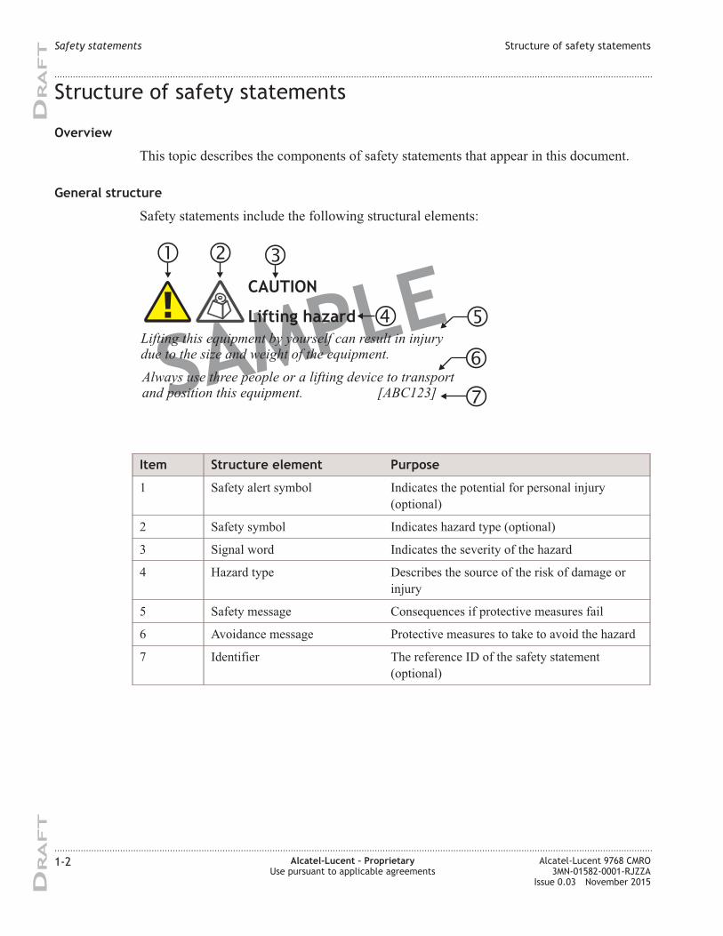
Safety statements include the following structural elements:
Item Structure element Purpose
1 Safety alert symbol Indicates the potential for personal injury
(optional)
2 Safety symbol Indicates hazard type (optional)
3 Signal word Indicates the severity of the hazard
4 Hazard type Describes the source of the risk of damage or
injury
5 Safety message Consequences if protective measures fail
6 Avoidance message Protective measures to take to avoid the hazard
7 Identifier The reference ID of the safety statement
(optional)
SAMPLELifting this equipment by yourself can result in injurydue to the size and weight of the equipment.
Always use three people or a lifting device to transportand position this equipment. [ABC123]
CAUTION
Lifting hazard
Safety statements Structure of safety statements
....................................................................................................................................................................................................................................
....................................................................................................................................................................................................................................
1-2 Alcatel-Lucent – Proprietary
Use pursuant to applicable agreements
Alcatel-Lucent 9768 CMRO
3MN-01582-0001-RJZZA
Issue 0.03 November 2015
DRA
FT
DRA
FT
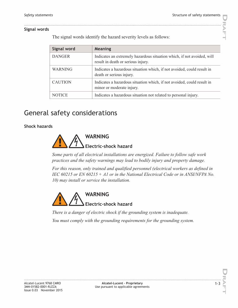
Signal words
The signal words identify the hazard severity levels as follows:
Signal word Meaning
DANGER Indicates an extremely hazardous situation which, if not avoided, will
result in death or serious injury.
WARNING Indicates a hazardous situation which, if not avoided, could result in
death or serious injury.
CAUTION Indicates a hazardous situation which, if not avoided, could result in
minor or moderate injury.
NOTICE Indicates a hazardous situation not related to personal injury.
General safety considerations
Shock hazards
WARNING
Electric-shock hazard
Some parts of all electrical installations are energized. Failure to follow safe work
practices and the safety warnings may lead to bodily injury and property damage.
For this reason, only trained and qualified personnel (electrical workers as defined in
IEC 60215 or EN 60215 + A1 or in the National Electrical Code or in ANSI/NFPA No.
10) may install or service the installation.
WARNING
Electric-shock hazard
There is a danger of electric shock if the grounding system is inadequate.
You must comply with the grounding requirements for the grounding system.
Safety statements Structure of safety statements
....................................................................................................................................................................................................................................
....................................................................................................................................................................................................................................
Alcatel-Lucent 9768 CMRO
3MN-01582-0001-RJZZA
Issue 0.03 November 2015
Alcatel-Lucent – Proprietary
Use pursuant to applicable agreements
1-3
DRA
FT
DRA
FT
Safety
General precautions for installation procedures
WARNING
Failure to observe these safety precautions may result in personal
injury or damage to equipment.
• Read and understand all instructions.
• Follow all warnings and instructions marked on this product.
• Installation and maintenance procedures must be followed and performed by
trained personnel only.
• The equipment must be provided with a readily accessible disconnect device
as part of site preparation.
• Grounding and circuit continuity is vital for safe operation of the equipment.
Never operate the equipment with grounding/bonding conductor
disconnected.
• Install only equipment identified in the product's installation manual. Use of
other equipment may result in an improper connection which could lead to
fire or injury.
• Use caution when installing or modifying telecommunications equipment.
• Before servicing, disconnect power input to reduce the risk of energy
hazards.
• For continued protection against risk of fire, all fuses used in this product
must be replaced only with fuses of the same type and rating.
• Never install telecommunications equipment during a lightning storm or
when conditions are wet.
• Never touch uninsulated wiring or terminals carrying direct current or
ringing current, and never leave this wiring exposed. Protect and tape
uninsulated wiring and terminals to avoid risk of fire, electrical shock, and
injury to personnel.
• Never spill liquids of any kind on the product.
• To reduce the risk of an electrical shock, do not disassemble the product.
Opening and removing covers and/or circuit boards may expose you to
dangerous voltages or other risks. Incorrect reassembly can cause electrical
shock when the unit is subsequently used.
• for PERMANENTLY CONNECTED EQUIPMENT, a readily accessible
disconnect device must be incorporated external to the equipment.
Safety statements Safety
....................................................................................................................................................................................................................................
....................................................................................................................................................................................................................................
1-4 Alcatel-Lucent – Proprietary
Use pursuant to applicable agreements
Alcatel-Lucent 9768 CMRO
3MN-01582-0001-RJZZA
Issue 0.03 November 2015
DRA
FT
DRA
FT
Safety - specific hazards
Danger
DANGER
Electric-shock hazard
Working in severe weather can result in personal injury or death and damage to the
equipment.
Never install or perform maintenance during severe weather (high winds, lightning,
blizzards, hurricane etc.).
DANGER
Noxious-substance hazard
Use of unspecified cleaning agents can result in personal injury.
Use only specified cleaning agents. Never use flammable solvents.
Always ensure that there is adequate ventilation in the work area and wear the
appropriate personal protective equipment.
Warning
WARNING
Laser hazard
Use of controls or adjustments or performance of procedures other than those specified
herein may result in hazardous laser radiation exposure.
Do not view directly into the laser beam with optical instruments such as a fiber
microscope because viewing of laser emission in excess of Class 1 limits significantly
increases the risk of eye damage.
Never look into the end of an exposed fiber or an open connector as long as the optical
source is switched on.
Ensure that the optical source is switched off before disconnecting optical fiber
connectors.
Safety statements Safety - specific hazards
....................................................................................................................................................................................................................................
....................................................................................................................................................................................................................................
Alcatel-Lucent 9768 CMRO
3MN-01582-0001-RJZZA
Issue 0.03 November 2015
Alcatel-Lucent – Proprietary
Use pursuant to applicable agreements
1-5
DRA
FT
DRA
FT
WARNING
Electric-shock hazard
Some parts of all electrical installations are energized. Failure to observe this fact and
the safety warnings may lead to bodily injury and property damage.
For this reason, only trained and qualified personnel (electrical workers as defined in
IEC 60215 + A1 or EN 60215) may install or service the installation.
WARNING
Electric-shock hazard
The power supply lines to the equipment are energized. Contact with parts carrying
current can cause serious injury, possibly including death, even hours after the event.
Turn off and lock out the system power at the disconnect device before working on or
servicing the equipment.
WARNING
Fall hazard
Falls can occur when working at heights resulting in serious personal injury or death.
To prevent a fall when working at heights (ladder, scaffold, manlift, roof etc.) follow safe
work practices and wear appropriate fall protection equipment.
Caution
CAUTION
RF hazard
RF exposure in excess of applicable limits can result in personal injury.
Metro Cells are designed and installed in order that they are compliant with the exposure
guidelines laid down by 47 CFR 1.1307 -1.1310.
For all staff that are required to work in close proximity to the equipment, for example
maintenance personnel, contact with the antenna should be avoided. No such persons
shall stay in front of the product at a distance of less than 8 cm.
No other persons shall stay in front of the product at a distance of less than 22 cm.
Safety statements Safety - specific hazards
....................................................................................................................................................................................................................................
....................................................................................................................................................................................................................................
1-6 Alcatel-Lucent – Proprietary
Use pursuant to applicable agreements
Alcatel-Lucent 9768 CMRO
3MN-01582-0001-RJZZA
Issue 0.03 November 2015
DRA
FT
DRA
FT
CAUTION
Electric-shock hazard
DOUBLE POLE/NEUTRAL FUSING
A fuse is used in the neutral of single-phase equipment either permanently connected or
provided with a non-reversible plug. After operation of the fuse, parts of the equipment
that remain energized might represent a hazard during servicing.
Failure to observe this fact and the safety warnings may lead to bodily injury and
property damage.
CAUTION
Hot-surface hazard
The surfaces of the CMRO can become hot enough to cause burns on unprotected skin.
On the product label, the universal symbol for Hot Surface (shown here) emphasizes this
hazard.
Before handling the unit, wait until its surfaces have cooled and, where the following
conditions apply, ensure that it is mounted out of the public's reach.
For installations in ambient temperatures exceeding 46° C, surface temperature may
exceed 70° C. In these situations, this equipment is intended for installation where access
is restricted to only qualified service personnel.
Safety statements Safety - specific hazards
....................................................................................................................................................................................................................................
....................................................................................................................................................................................................................................
Alcatel-Lucent 9768 CMRO
3MN-01582-0001-RJZZA
Issue 0.03 November 2015
Alcatel-Lucent – Proprietary
Use pursuant to applicable agreements
1-7
DRA
FT
DRA
FT
Notices
NOTICE
ESD hazard
Semiconductor devices can be damaged by electrostatic discharges (ESD)
The following rules must be complied with when handling any module containing
semiconductor components:
• Wear conductive or antistatic working clothes (for example, coat made of 100%
cotton).
• Wear a grounded wrist strap.
• Wear shoes with conductive soles on a conductive floor surface or conductive work
mat.
• Leave the modules in their original packaging until ready for use.
• Make sure there is no difference in potential between yourself, the workplace, and the
packaging before removing, unpacking, or packing a module.
• Whenever handling ESD-sensitive components, do not touch any connection pins or
tracks.
• Place modules removed from the equipment on a conductive surface.
• Test or handle the module only with grounded tools on grounded equipment.
• Handle defective modules exactly like new ones to avoid causing further damage.
NOTICE
Condensation
Sudden changes in the weather may lead to the formation of condensation on
components. Operating the unit when condensation moisture is present can destroy the
unit.
Units which show signs of condensation must be dried before installation.
NOTICE
Tools
Tools left in the working area can cause short circuits during operation which can lead to
the destruction of units.
Make sure after finishing your work that no tools, testing equipment, flashlights, etc.,
have been left in or on the equipment.
Safety statements Safety - specific hazards
....................................................................................................................................................................................................................................
....................................................................................................................................................................................................................................
1-8 Alcatel-Lucent – Proprietary
Use pursuant to applicable agreements
Alcatel-Lucent 9768 CMRO
3MN-01582-0001-RJZZA
Issue 0.03 November 2015
DRA
FT
DRA
FT
Product safety
Equipment safety
Safety information for this equipment can be found on various Caution, Warning, Danger,
information labels or instructions affixed to or included with the product or included
within this document. Informational and cautionary labels may appear near the item they
address or may be grouped in a single location on the equipment. Warnings are typically
adjacent to the hazard that is noted on the label. The instructions, cautions and warnings
found on these labels must be understood and observed by all personnel involved with the
equipment installation and maintenance.
Safety statements Product safety
....................................................................................................................................................................................................................................
....................................................................................................................................................................................................................................
Alcatel-Lucent 9768 CMRO
3MN-01582-0001-RJZZA
Issue 0.03 November 2015
Alcatel-Lucent – Proprietary
Use pursuant to applicable agreements
1-9
DRA
FT
DRA
FT
Safety statements Product safety
....................................................................................................................................................................................................................................
....................................................................................................................................................................................................................................
1-10 Alcatel-Lucent – Proprietary
Use pursuant to applicable agreements
Alcatel-Lucent 9768 CMRO
3MN-01582-0001-RJZZA
Issue 0.03 November 2015
DRA
FT
DRA
FT
2 2Hardware architecture
and functionality
Overview
Purpose
This chapter provides a high-level overview of the Alcatel-Lucent 9768 Compact Metro
Radio Outdoor (9768 CMRO) product and functionality.
Contents
Functional description 2-1
Physical description 2-3
7705 SAR-O hardware overview and ancillary 2-9
Supported installation options 2-15
Hardware and ancillary items 2-25
Functional description
Overview
The Alcatel-Lucent 9768 Compact Metro Radio Outdoor product is a next-generation
Metro Radio Outdoor product with 10x the output power at half the size when compared
with the Alcatel-Lucent 9768 Metro Radio Outdoor (9768 MRO), that enables mobile
service providers (MSPs) to deliver cost-effective capacity to urban hotspots, for
example, stadiums, campuses, train stations, bus stops and other urban environments, as
well as affordable coverage to rural locations. It is designed to be deployed as an overlay
in an existing macro coverage area to provide increased coverage in public open spaces.
...................................................................................................................................................................................................................................
Alcatel-Lucent 9768 CMRO
3MN-01582-0001-RJZZA
Issue 0.03 November 2015
Alcatel-Lucent – Proprietary
Use pursuant to applicable agreements
2-1
DRA
FT
DRA
FT
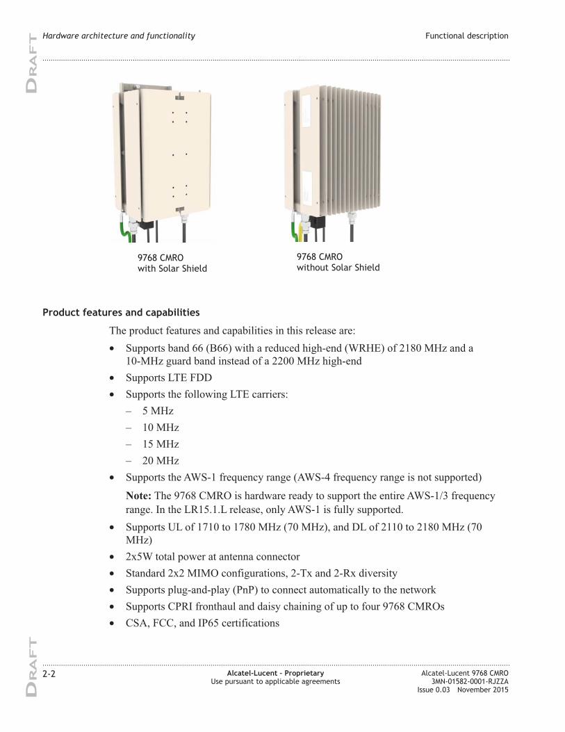
Product features and capabilities
The product features and capabilities in this release are:
• Supports band 66 (B66) with a reduced high-end (WRHE) of 2180 MHz and a
10-MHz guard band instead of a 2200 MHz high-end
• Supports LTE FDD
• Supports the following LTE carriers:
– 5 MHz
– 10 MHz
– 15 MHz
– 20 MHz
• Supports the AWS-1 frequency range (AWS-4 frequency range is not supported)
Note: The 9768 CMRO is hardware ready to support the entire AWS-1/3 frequency
range. In the LR15.1.L release, only AWS-1 is fully supported.
• Supports UL of 1710 to 1780 MHz (70 MHz), and DL of 2110 to 2180 MHz (70
MHz)
• 2x5W total power at antenna connector
• Standard 2x2 MIMO configurations, 2-Tx and 2-Rx diversity
• Supports plug-and-play (PnP) to connect automatically to the network
• Supports CPRI fronthaul and daisy chaining of up to four 9768 CMROs
• CSA, FCC, and IP65 certifications
9768 CMRO
with Solar Shield
9768 CMRO
without Solar Shield
Hardware architecture and functionality Functional description
....................................................................................................................................................................................................................................
....................................................................................................................................................................................................................................
2-2 Alcatel-Lucent – Proprietary
Use pursuant to applicable agreements
Alcatel-Lucent 9768 CMRO
3MN-01582-0001-RJZZA
Issue 0.03 November 2015
DRA
FT
DRA
FT
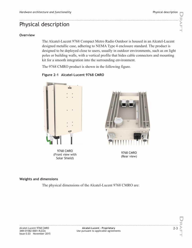
Physical description
Overview
The Alcatel-Lucent 9768 Compact Metro Radio Outdoor is housed in an Alcatel-Lucent
designed metallic case, adhering to NEMA Type 4 enclosure standard. The product is
designed to be deployed close to users, usually in outdoor environments, such as on light
poles or building walls, with a vertical profile that hides cable connectors and mounting
kit for a smooth integration into the surrounding environment.
The 9768 CMRO product is shown in the following figure.
Weights and dimensions
The physical dimensions of the Alcatel-Lucent 9768 CMRO are:
Figure 2-1 Alcatel-Lucent 9768 CMRO
9768 CMRO
(Front view with
Solar Shield)
9768 CMRO
(Rear view)
Hardware architecture and functionality Physical description
....................................................................................................................................................................................................................................
....................................................................................................................................................................................................................................
Alcatel-Lucent 9768 CMRO
3MN-01582-0001-RJZZA
Issue 0.03 November 2015
Alcatel-Lucent – Proprietary
Use pursuant to applicable agreements
2-3
DRA
FT
DRA
FT
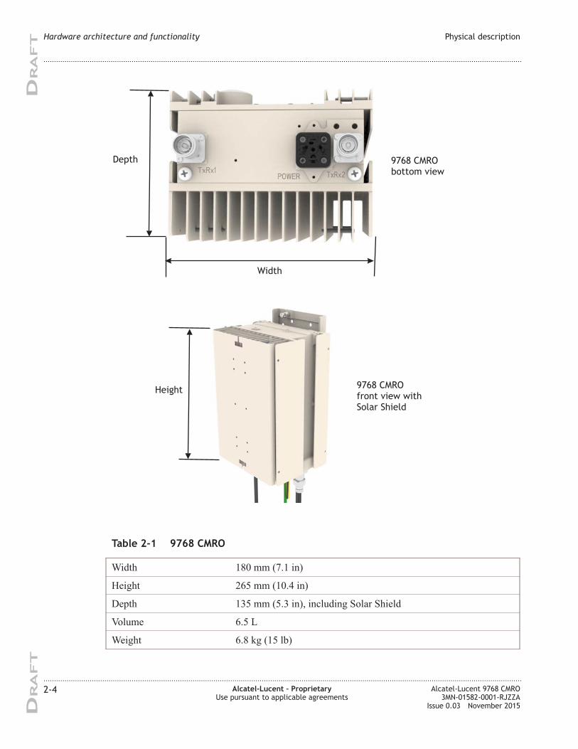
Table 2-1 9768 CMRO
Width 180 mm (7.1 in)
Height 265 mm (10.4 in)
Depth 135 mm (5.3 in), including Solar Shield
Volume 6.5 L
Weight 6.8 kg (15 lb)
Height
Width
Depth
9768 CMRO
front view with
Solar Shield
9768 CMRO
bottom view
Hardware architecture and functionality Physical description
....................................................................................................................................................................................................................................
....................................................................................................................................................................................................................................
2-4 Alcatel-Lucent – Proprietary
Use pursuant to applicable agreements
Alcatel-Lucent 9768 CMRO
3MN-01582-0001-RJZZA
Issue 0.03 November 2015
DRA
FT
DRA
FT
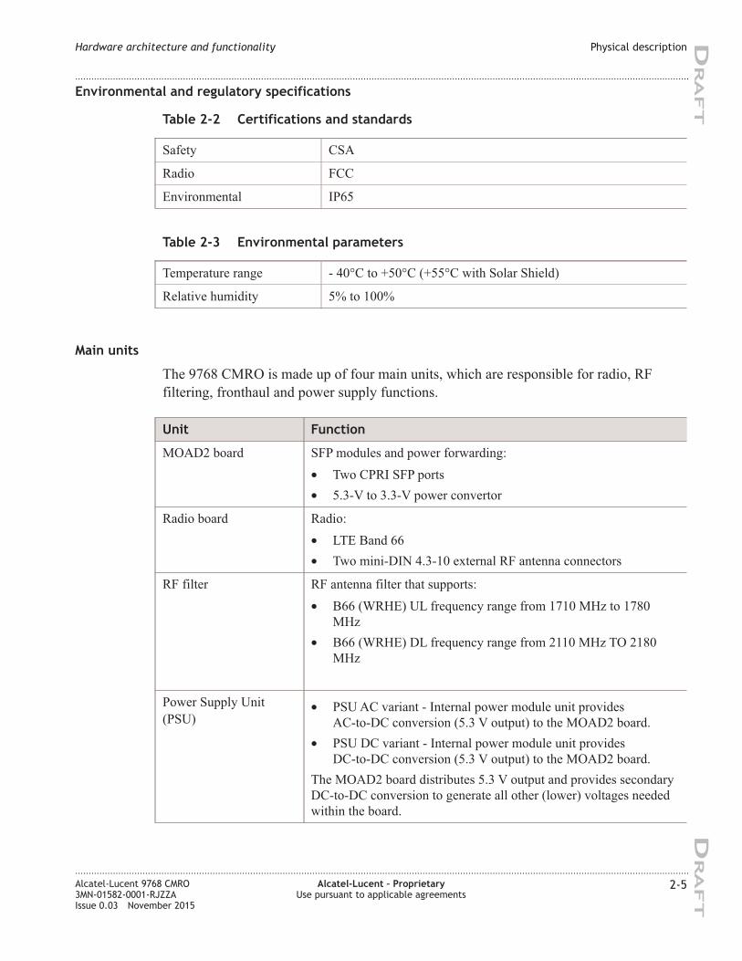
Environmental and regulatory specifications
Table 2-2 Certifications and standards
Safety CSA
Radio FCC
Environmental IP65
Table 2-3 Environmental parameters
Temperature range - 40°C to +50°C (+55°C with Solar Shield)
Relative humidity 5% to 100%
Main units
The 9768 CMRO is made up of four main units, which are responsible for radio, RF
filtering, fronthaul and power supply functions.
Unit Function
MOAD2 board SFP modules and power forwarding:
• Two CPRI SFP ports
• 5.3-V to 3.3-V power convertor
Radio board Radio:
• LTE Band 66
• Two mini-DIN 4.3-10 external RF antenna connectors
RF filter RF antenna filter that supports:
• B66 (WRHE) UL frequency range from 1710 MHz to 1780
MHz
• B66 (WRHE) DL frequency range from 2110 MHz TO 2180
MHz
Power Supply Unit
(PSU)
• PSU AC variant - Internal power module unit provides
AC-to-DC conversion (5.3 V output) to the MOAD2 board.
• PSU DC variant - Internal power module unit provides
DC-to-DC conversion (5.3 V output) to the MOAD2 board.
The MOAD2 board distributes 5.3 V output and provides secondary
DC-to-DC conversion to generate all other (lower) voltages needed
within the board.
Hardware architecture and functionality Physical description
....................................................................................................................................................................................................................................
....................................................................................................................................................................................................................................
Alcatel-Lucent 9768 CMRO
3MN-01582-0001-RJZZA
Issue 0.03 November 2015
Alcatel-Lucent – Proprietary
Use pursuant to applicable agreements
2-5
DRA
FT
DRA
FT
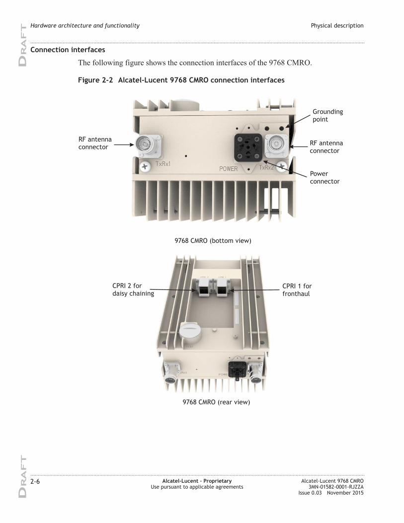
Connection interfaces
The following figure shows the connection interfaces of the 9768 CMRO.
Figure 2-2 Alcatel-Lucent 9768 CMRO connection interfaces
RF antenna
connectorRF antenna
connector
Power
connector
Grounding
point
9768 CMRO (bottom view)
9768 CMRO (rear view)
CPRI 2 for
daisy chaining
CPRI 1 for
fronthaul
Hardware architecture and functionality Physical description
....................................................................................................................................................................................................................................
....................................................................................................................................................................................................................................
2-6 Alcatel-Lucent – Proprietary
Use pursuant to applicable agreements
Alcatel-Lucent 9768 CMRO
3MN-01582-0001-RJZZA
Issue 0.03 November 2015
DRA
FT
DRA
FT
Connection location Description
9768 CMRO (bottom) Power supply connector (AC or DC)
Two mini-DIN 4.3-10 RF antenna connectors
Grounding point
9768 CMRO (rear) Two CPRI SFP ports; “CPRI 1” and “CPRI 2”
“CPRI 1” is used to connect to the BBU or to daisy-chain with
another 9768 CMRO and “CPRI 2” is used to daisy chain to the
next 9768 CMRO
Power supply
The Alcatel-Lucent 9768 CMRO product supports either AC or DC external power input.
9768 CMRO Power supply details
AC variant AC power supply that operates from a single phase, three wire voltage
source in the 95 to 265 Volt range.
The AC power is surge protected internally, and conforms to IEC
60364-1 and GR-1089-Core, Issue 6, Section 4.6.2, Table 4-2 Surge
Test #20.
Fully configured and operating at maximum levels, the product
consumes 100 W. Typical power consumption is 85 W.
DC variant -48 V DC power supply that operates over the voltage range from -40 V
DC to -57 V DC.
The DC power is surge protected internally, and conforms to GR-1089,
Issue 6, Appendix B for Port Type 8a.
Fully configured and operating at maximum levels, the product
consumes 100 W. Typical power consumption is 85 W.
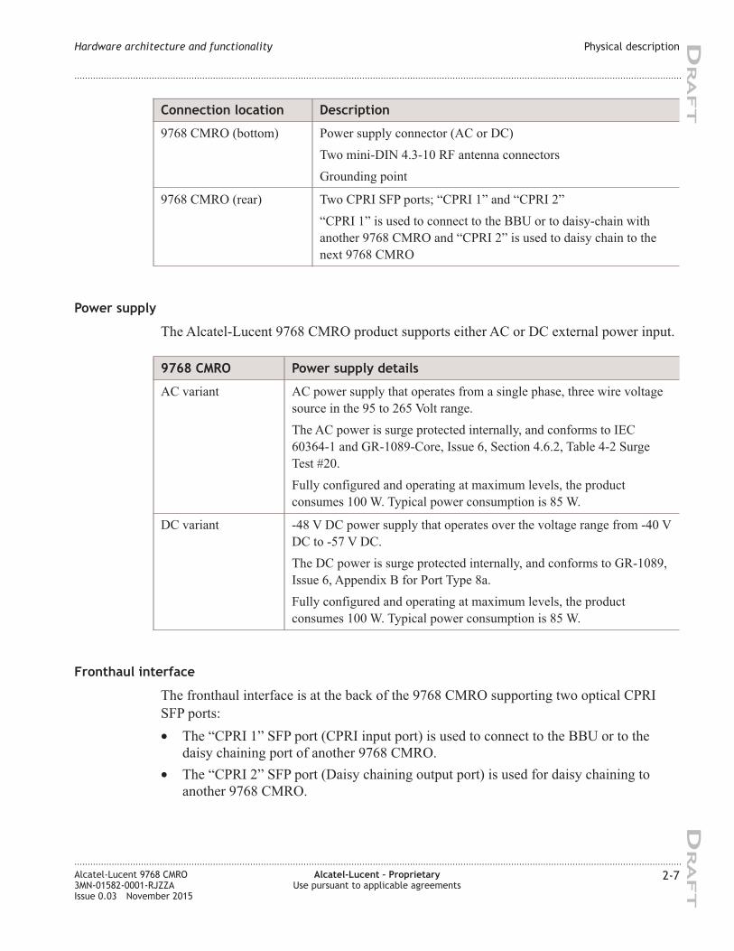
Fronthaul interface
The fronthaul interface is at the back of the 9768 CMRO supporting two optical CPRI
SFP ports:
• The “CPRI 1” SFP port (CPRI input port) is used to connect to the BBU or to the
daisy chaining port of another 9768 CMRO.
• The “CPRI 2” SFP port (Daisy chaining output port) is used for daisy chaining to
another 9768 CMRO.
Hardware architecture and functionality Physical description
....................................................................................................................................................................................................................................
....................................................................................................................................................................................................................................
Alcatel-Lucent 9768 CMRO
3MN-01582-0001-RJZZA
Issue 0.03 November 2015
Alcatel-Lucent – Proprietary
Use pursuant to applicable agreements
2-7
DRA
FT
DRA
FT
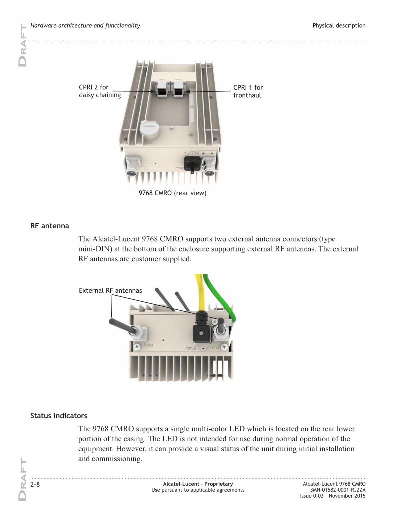
RF antenna
The Alcatel-Lucent 9768 CMRO supports two external antenna connectors (type
mini-DIN) at the bottom of the enclosure supporting external RF antennas. The external
RF antennas are customer supplied.
Status indicators
The 9768 CMRO supports a single multi-color LED which is located on the rear lower
portion of the casing. The LED is not intended for use during normal operation of the
equipment. However, it can provide a visual status of the unit during initial installation
and commissioning.
9768 CMRO (rear view)
9768 CMRO (rear view)
CPRI 2 for
daisy chaining
CPRI 1 for
fronthaul
External RF antennas
Hardware architecture and functionality Physical description
....................................................................................................................................................................................................................................
....................................................................................................................................................................................................................................
2-8 Alcatel-Lucent – Proprietary
Use pursuant to applicable agreements
Alcatel-Lucent 9768 CMRO
3MN-01582-0001-RJZZA
Issue 0.03 November 2015
DRA
FT
DRA
FT
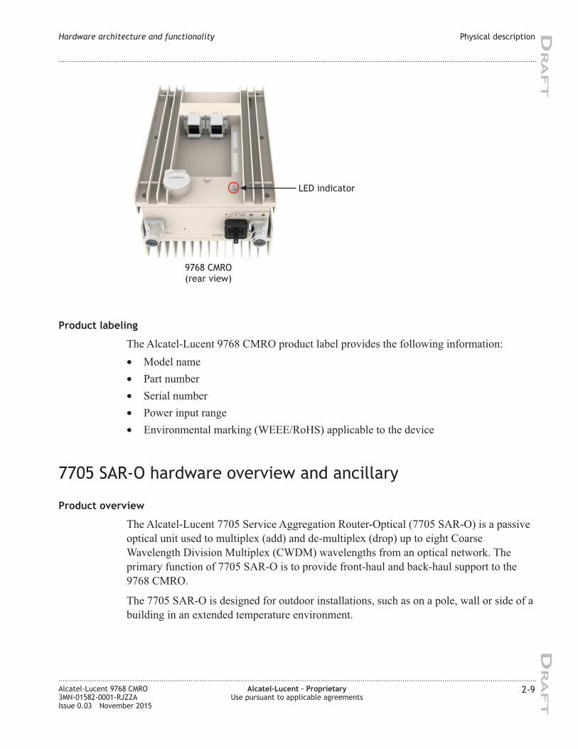
Product labeling
The Alcatel-Lucent 9768 CMRO product label provides the following information:
• Model name
• Part number
• Serial number
• Power input range
• Environmental marking (WEEE/RoHS) applicable to the device
7705 SAR-O hardware overview and ancillary
Product overview
The Alcatel-Lucent 7705 Service Aggregation Router-Optical (7705 SAR-O) is a passive
optical unit used to multiplex (add) and de-multiplex (drop) up to eight Coarse
Wavelength Division Multiplex (CWDM) wavelengths from an optical network. The
primary function of 7705 SAR-O is to provide front-haul and back-haul support to the
9768 CMRO.
The 7705 SAR-O is designed for outdoor installations, such as on a pole, wall or side of a
building in an extended temperature environment.
LED indicator
9768 CMRO
(rear view)
Hardware architecture and functionality Physical description
....................................................................................................................................................................................................................................
....................................................................................................................................................................................................................................
Alcatel-Lucent 9768 CMRO
3MN-01582-0001-RJZZA
Issue 0.03 November 2015
Alcatel-Lucent – Proprietary
Use pursuant to applicable agreements
2-9
DRA
FT
DRA
FT
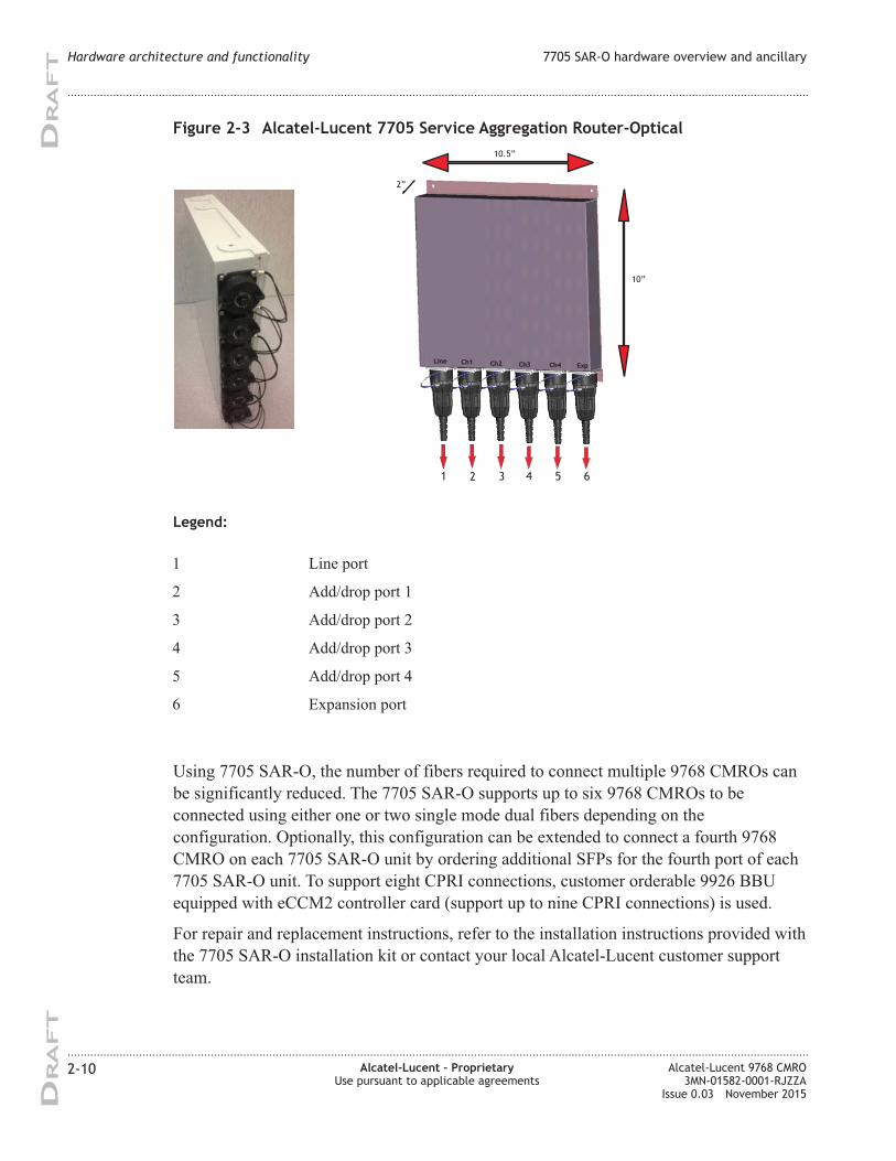
Legend:
1 Line port
2 Add/drop port 1
3 Add/drop port 2
4 Add/drop port 3
5 Add/drop port 4
6 Expansion port
Using 7705 SAR-O, the number of fibers required to connect multiple 9768 CMROs can
be significantly reduced. The 7705 SAR-O supports up to six 9768 CMROs to be
connected using either one or two single mode dual fibers depending on the
configuration. Optionally, this configuration can be extended to connect a fourth 9768
CMRO on each 7705 SAR-O unit by ordering additional SFPs for the fourth port of each
7705 SAR-O unit. To support eight CPRI connections, customer orderable 9926 BBU
equipped with eCCM2 controller card (support up to nine CPRI connections) is used.
For repair and replacement instructions, refer to the installation instructions provided with
the 7705 SAR-O installation kit or contact your local Alcatel-Lucent customer support
team.
Figure 2-3 Alcatel-Lucent 7705 Service Aggregation Router-Optical
Line Ch1 Ch2 Ch3 Ch4 Exp
10.5”
10”
2”
1 2 3 4 5 6
Hardware architecture and functionality 7705 SAR-O hardware overview and ancillary
....................................................................................................................................................................................................................................
....................................................................................................................................................................................................................................
2-10 Alcatel-Lucent – Proprietary
Use pursuant to applicable agreements
Alcatel-Lucent 9768 CMRO
3MN-01582-0001-RJZZA
Issue 0.03 November 2015
DRA
FT
DRA
FT
Power supply
The 7705 SAR-O does not require an external power supply (a passive unit).
Dimensions
The following table provides the dimensions of only the 7705 SAR-O.
Table 2-4 7705 SAR-O dimensions
7705 SAR-O (H x W x D) 10.24 x 10.05 x 2.17 inches
7705 SAR-O 4.0 lbs (1.8 kg)
Chassis
The 4-Wavelength CWDM Dual-Fiber variant of 7705 SAR-O is used for installation
with the 9768 CMRO.
4-Wavelength CWDM Dual-Fiber
The 4-wavelength CWDM dual-fiber is used to drop and add four specific wavelengths
from the network. However, other wavelengths are allowed to pass through. This variant
can also add other wavelengths and allow a 1310 nm signal to pass through in the case of
a CWDM OADM linear 1310 nm application.
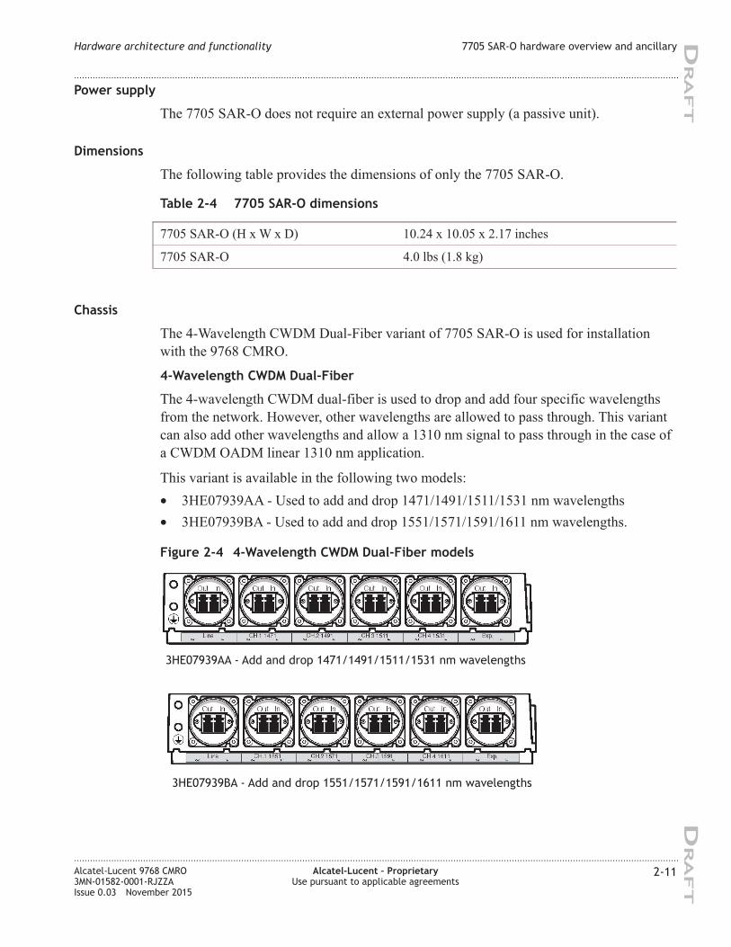
This variant is available in the following two models:
• 3HE07939AA - Used to add and drop 1471/1491/1511/1531 nm wavelengths
• 3HE07939BA - Used to add and drop 1551/1571/1591/1611 nm wavelengths.
Figure 2-4 4-Wavelength CWDM Dual-Fiber models
3HE07939AA - Add and drop 1471/1491/1511/1531 nm wavelengths
3HE07939BA - Add and drop 1551/1571/1591/1611 nm wavelengths
Hardware architecture and functionality 7705 SAR-O hardware overview and ancillary
....................................................................................................................................................................................................................................
....................................................................................................................................................................................................................................
Alcatel-Lucent 9768 CMRO
3MN-01582-0001-RJZZA
Issue 0.03 November 2015
Alcatel-Lucent – Proprietary
Use pursuant to applicable agreements
2-11
DRA
FT
DRA
FT
7705 SAR-O installation with 9768 CMRO
For installation configuration of 7705 SAR-O with 9768 CMRO, refer to the 7705 SAR-O
Quick Start Guide provided within the “Kit SAR-O” (p. 2-13).
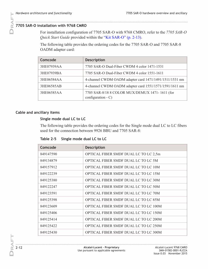
The following table provides the ordering codes for the 7705 SAR-O and 7705 SAR-8
OADM adapter card:
Comcode Description
3HE07939AA 7705 SAR-O Dual-Fiber CWDM 4 color 1471-1531
3HE07939BA 7705 SAR-O Dual-Fiber CWDM 4 color 1551-1611
3HE06584AA 4-channel CWDM OADM adapter card 1471/1491/1511/1531 nm
3HE06585AB 4-channel CWDM OADM adapter card 1551/1571/1591/1611 nm
3HE06585AA 7705 SAR-8/18 8 COLOR MUX/DEMUX 1471- 1611 (for
configuration - C)
Cable and ancillary items
Single mode dual LC to LC
The following table provides the ordering codes for the Single mode dual LC to LC fibers
used for the connection between 9926 BBU and 7705 SAR-8:
Table 2-5 Single mode dual LC to LC
Comcode Description
849147590 OPTICAL FIBER SMDF DUAL LC TO LC 2,5m
849134879 OPTICAL FIBER SMDF DUAL LC TO LC 5M
849157912 OPTICAL FIBER SMDF DUAL LC TO LC 10M
849122239 OPTICAL FIBER SMDF DUAL LC TO LC 15M
849125380 OPTICAL FIBER SMDF DUAL LC TO LC 30M
849122247 OPTICAL FIBER SMDF DUAL LC TO LC 50M
849123591 OPTICAL FIBER SMDF DUAL LC TO LC 70M
849125398 OPTICAL FIBER SMDF DUAL LC TO LC 85M
849123609 OPTICAL FIBER SMDF DUAL LC TO LC 100M
849125406 OPTICAL FIBER SMDF DUAL LC TO LC 150M
849125414 OPTICAL FIBER SMDF DUAL LC TO LC 200M
849125422 OPTICAL FIBER SMDF DUAL LC TO LC 250M
849125430 OPTICAL FIBER SMDF DUAL LC TO LC 300M
Hardware architecture and functionality 7705 SAR-O hardware overview and ancillary
....................................................................................................................................................................................................................................
....................................................................................................................................................................................................................................
2-12 Alcatel-Lucent – Proprietary
Use pursuant to applicable agreements
Alcatel-Lucent 9768 CMRO
3MN-01582-0001-RJZZA
Issue 0.03 November 2015
DRA
FT
DRA
FT
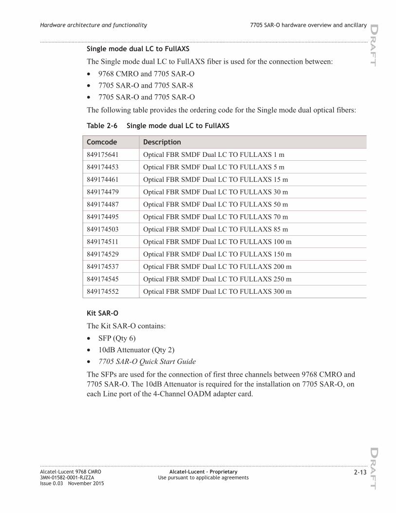
Single mode dual LC to FullAXS
The Single mode dual LC to FullAXS fiber is used for the connection between:
• 9768 CMRO and 7705 SAR-O
• 7705 SAR-O and 7705 SAR-8
• 7705 SAR-O and 7705 SAR-O
The following table provides the ordering code for the Single mode dual optical fibers:
Table 2-6 Single mode dual LC to FullAXS
Comcode Description
849175641 Optical FBR SMDF Dual LC TO FULLAXS 1 m
849174453 Optical FBR SMDF Dual LC TO FULLAXS 5 m
849174461 Optical FBR SMDF Dual LC TO FULLAXS 15 m
849174479 Optical FBR SMDF Dual LC TO FULLAXS 30 m
849174487 Optical FBR SMDF Dual LC TO FULLAXS 50 m
849174495 Optical FBR SMDF Dual LC TO FULLAXS 70 m
849174503 Optical FBR SMDF Dual LC TO FULLAXS 85 m
849174511 Optical FBR SMDF Dual LC TO FULLAXS 100 m
849174529 Optical FBR SMDF Dual LC TO FULLAXS 150 m
849174537 Optical FBR SMDF Dual LC TO FULLAXS 200 m
849174545 Optical FBR SMDF Dual LC TO FULLAXS 250 m
849174552 Optical FBR SMDF Dual LC TO FULLAXS 300 m
Kit SAR-O
The Kit SAR-O contains:
• SFP (Qty 6)
• 10dB Attenuator (Qty 2)
• 7705 SAR-O Quick Start Guide
The SFPs are used for the connection of first three channels between 9768 CMRO and
7705 SAR-O. The 10dB Attenuator is required for the installation on 7705 SAR-O, on
each Line port of the 4-Channel OADM adapter card.
Hardware architecture and functionality 7705 SAR-O hardware overview and ancillary
....................................................................................................................................................................................................................................
....................................................................................................................................................................................................................................
Alcatel-Lucent 9768 CMRO
3MN-01582-0001-RJZZA
Issue 0.03 November 2015
Alcatel-Lucent – Proprietary
Use pursuant to applicable agreements
2-13
DRA
FT
DRA
FT
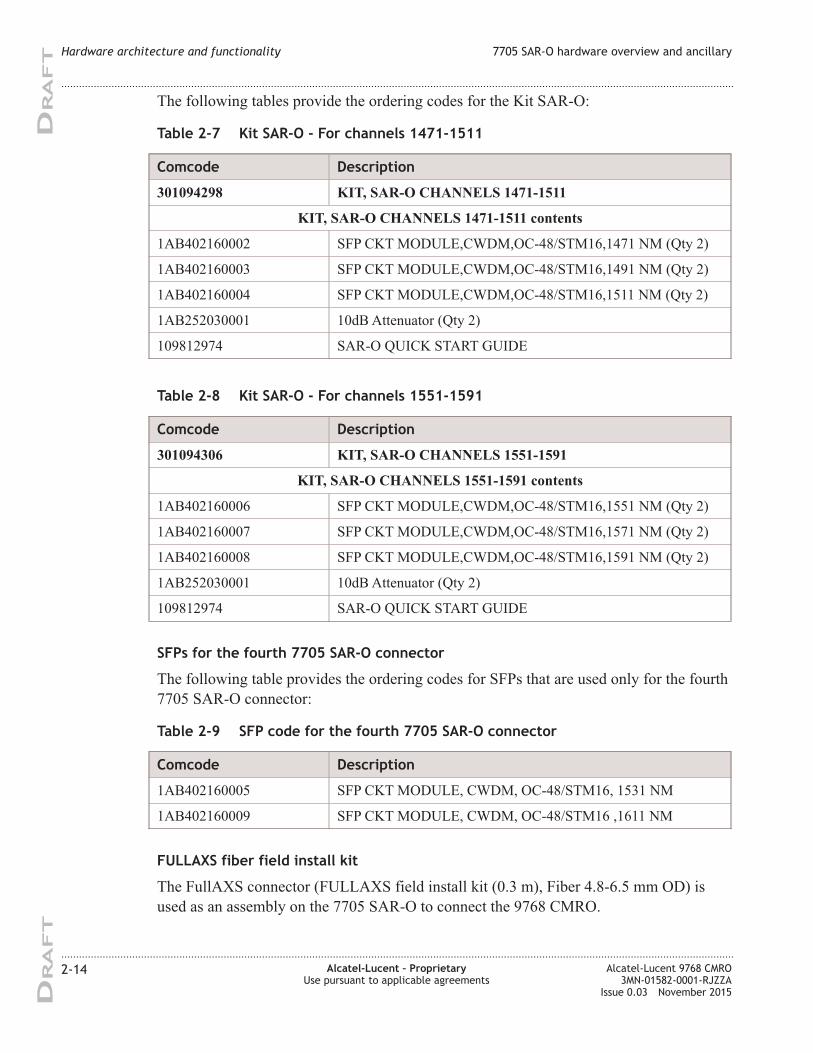
The following tables provide the ordering codes for the Kit SAR-O:
Table 2-7 Kit SAR-O - For channels 1471-1511
Comcode Description
301094298 KIT, SAR-O CHANNELS 1471-1511
KIT, SAR-O CHANNELS 1471-1511 contents
1AB402160002 SFP CKT MODULE,CWDM,OC-48/STM16,1471 NM (Qty 2)
1AB402160003 SFP CKT MODULE,CWDM,OC-48/STM16,1491 NM (Qty 2)
1AB402160004 SFP CKT MODULE,CWDM,OC-48/STM16,1511 NM (Qty 2)
1AB252030001 10dB Attenuator (Qty 2)
109812974 SAR-O QUICK START GUIDE
Table 2-8 Kit SAR-O - For channels 1551-1591
Comcode Description
301094306 KIT, SAR-O CHANNELS 1551-1591
KIT, SAR-O CHANNELS 1551-1591 contents
1AB402160006 SFP CKT MODULE,CWDM,OC-48/STM16,1551 NM (Qty 2)
1AB402160007 SFP CKT MODULE,CWDM,OC-48/STM16,1571 NM (Qty 2)
1AB402160008 SFP CKT MODULE,CWDM,OC-48/STM16,1591 NM (Qty 2)
1AB252030001 10dB Attenuator (Qty 2)
109812974 SAR-O QUICK START GUIDE
SFPs for the fourth 7705 SAR-O connector
The following table provides the ordering codes for SFPs that are used only for the fourth
7705 SAR-O connector:
Table 2-9 SFP code for the fourth 7705 SAR-O connector
Comcode Description
1AB402160005 SFP CKT MODULE, CWDM, OC-48/STM16, 1531 NM
1AB402160009 SFP CKT MODULE, CWDM, OC-48/STM16 ,1611 NM
FULLAXS fiber field install kit
The FullAXS connector (FULLAXS field install kit (0.3 m), Fiber 4.8-6.5 mm OD) is
used as an assembly on the 7705 SAR-O to connect the 9768 CMRO.
Hardware architecture and functionality 7705 SAR-O hardware overview and ancillary
....................................................................................................................................................................................................................................
....................................................................................................................................................................................................................................
2-14 Alcatel-Lucent – Proprietary
Use pursuant to applicable agreements
Alcatel-Lucent 9768 CMRO
3MN-01582-0001-RJZZA
Issue 0.03 November 2015
DRA
FT
DRA
FT

The following table provides the ordering code for the FULLAXS field install kit (0.3 m),
Fiber 4.8-6.5 mm OD:
Table 2-10 FULLAXS fiber field install kit
Comcode Description
1AB431220004 FULLAXS Fiber Field Install Kit (0.3m), FIBER 4.8-6.5 mm OD
Supported installation options
Overview
The following section describes the supported installation options for the Alcatel-Lucent
9768 CMRO product. These include:
• Standard installation options for 9768 CMRO (pole and wall-mount installation).
• 9768 CMRO (AC or DC variant) with 7705 SAR-O, separate mount installation
options
• Strand-mount installation option, where one or two DC powered 9768 CMROs, an
90v AC Coax to -48v DC converter and the RF antennas are mounted on a cable
strand.
• Daisy chain installation options, where up to four 9768 CMROs can be daisy-chained
together and share the same fronthaul port.
• Pair-mounted installation options, where two 9768 CMROs are mounted side-by-side
using a double Metro plate.
• Other co-located installation options, where two 9768 CMROs are mounted
side-by-side or one on top of another, without using a double Metro plate.
Standard installation options
The standard installation options include pole (light poles, lamp posts and so on) and
wall-mount (building walls) installations.
Hardware architecture and functionality 7705 SAR-O hardware overview and ancillary
....................................................................................................................................................................................................................................
....................................................................................................................................................................................................................................
Alcatel-Lucent 9768 CMRO
3MN-01582-0001-RJZZA
Issue 0.03 November 2015
Alcatel-Lucent – Proprietary
Use pursuant to applicable agreements
2-15
DRA
FT
DRA
FT
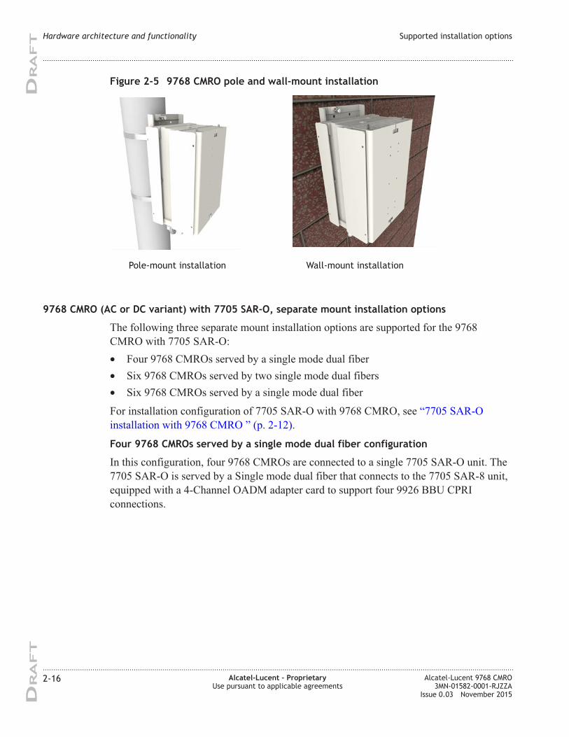
9768 CMRO (AC or DC variant) with 7705 SAR-O, separate mount installation options
The following three separate mount installation options are supported for the 9768
CMRO with 7705 SAR-O:
• Four 9768 CMROs served by a single mode dual fiber
• Six 9768 CMROs served by two single mode dual fibers
• Six 9768 CMROs served by a single mode dual fiber
For installation configuration of 7705 SAR-O with 9768 CMRO, see “7705 SAR-O
installation with 9768 CMRO ” (p. 2-12).
Four 9768 CMROs served by a single mode dual fiber configuration
In this configuration, four 9768 CMROs are connected to a single 7705 SAR-O unit. The
7705 SAR-O is served by a Single mode dual fiber that connects to the 7705 SAR-8 unit,
equipped with a 4-Channel OADM adapter card to support four 9926 BBU CPRI
connections.
Figure 2-5 9768 CMRO pole and wall-mount installation
Pole-mount installation Wall-mount installation
Hardware architecture and functionality Supported installation options
....................................................................................................................................................................................................................................
....................................................................................................................................................................................................................................
2-16 Alcatel-Lucent – Proprietary
Use pursuant to applicable agreements
Alcatel-Lucent 9768 CMRO
3MN-01582-0001-RJZZA
Issue 0.03 November 2015
DRA
FT
DRA
FT
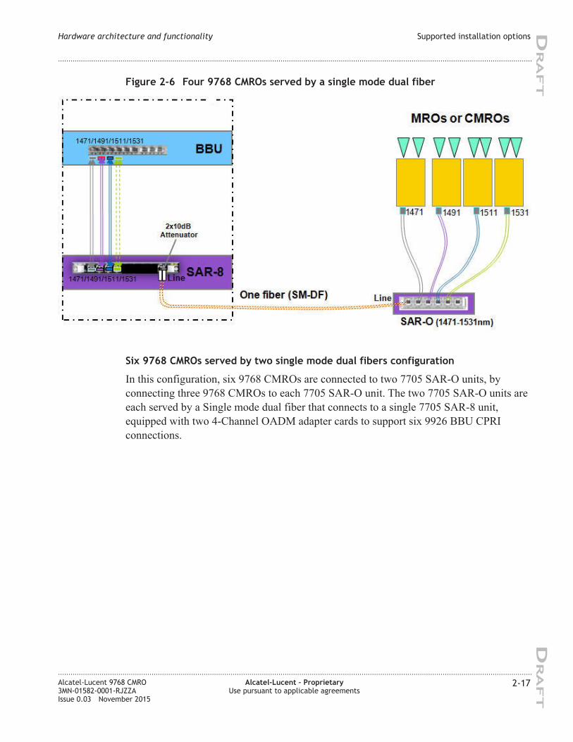
Six 9768 CMROs served by two single mode dual fibers configuration
In this configuration, six 9768 CMROs are connected to two 7705 SAR-O units, by
connecting three 9768 CMROs to each 7705 SAR-O unit. The two 7705 SAR-O units are
each served by a Single mode dual fiber that connects to a single 7705 SAR-8 unit,
equipped with two 4-Channel OADM adapter cards to support six 9926 BBU CPRI
connections.
Figure 2-6 Four 9768 CMROs served by a single mode dual fiber
Hardware architecture and functionality Supported installation options
....................................................................................................................................................................................................................................
....................................................................................................................................................................................................................................
Alcatel-Lucent 9768 CMRO
3MN-01582-0001-RJZZA
Issue 0.03 November 2015
Alcatel-Lucent – Proprietary
Use pursuant to applicable agreements
2-17
DRA
FT
DRA
FT
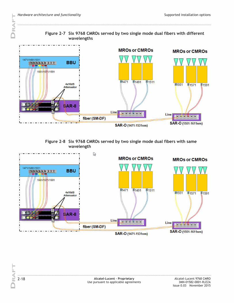
Figure 2-7 Six 9768 CMROs served by two single mode dual fibers with different
wavelengths
Figure 2-8 Six 9768 CMROs served by two single mode dual fibers with same
wavelength
Hardware architecture and functionality Supported installation options
....................................................................................................................................................................................................................................
....................................................................................................................................................................................................................................
2-18 Alcatel-Lucent – Proprietary
Use pursuant to applicable agreements
Alcatel-Lucent 9768 CMRO
3MN-01582-0001-RJZZA
Issue 0.03 November 2015
DRA
FT
DRA
FT
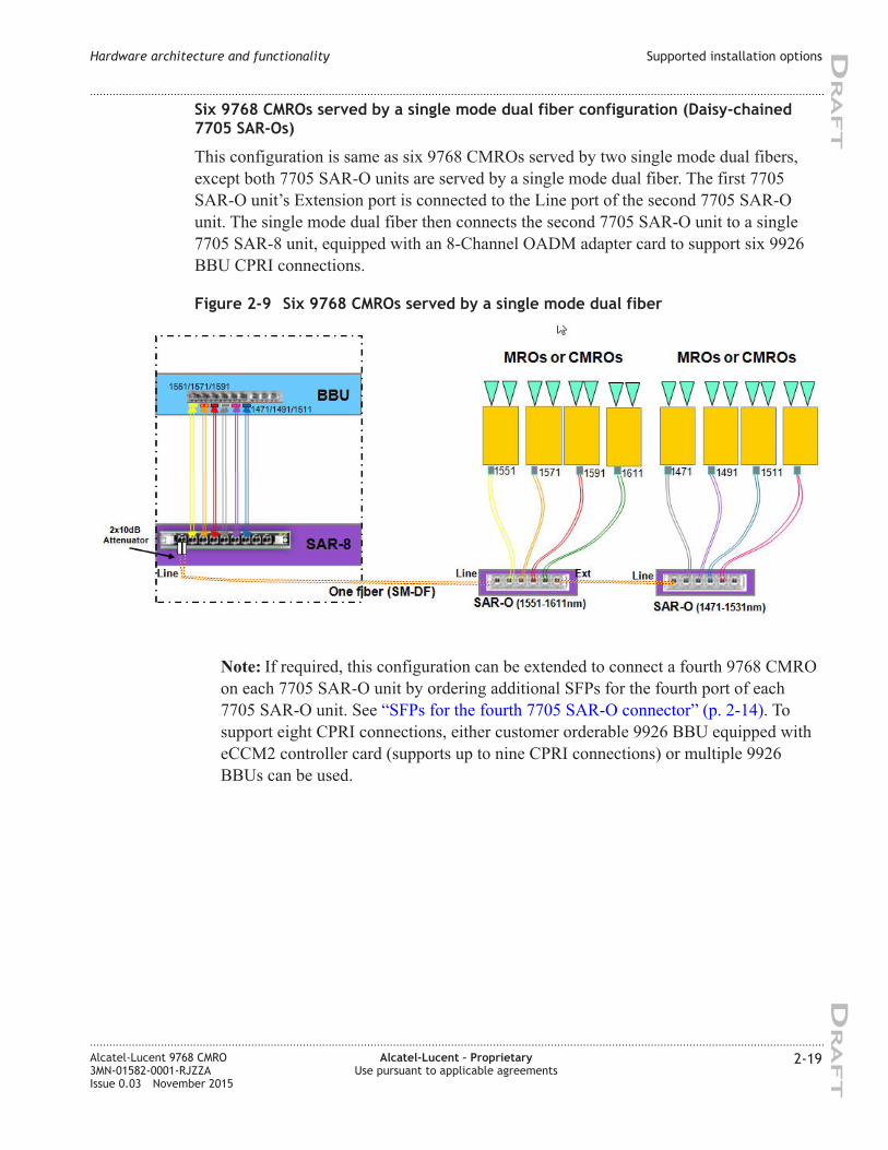
Six 9768 CMROs served by a single mode dual fiber configuration (Daisy-chained
7705 SAR-Os)
This configuration is same as six 9768 CMROs served by two single mode dual fibers,
except both 7705 SAR-O units are served by a single mode dual fiber. The first 7705
SAR-O unit’s Extension port is connected to the Line port of the second 7705 SAR-O
unit. The single mode dual fiber then connects the second 7705 SAR-O unit to a single
7705 SAR-8 unit, equipped with an 8-Channel OADM adapter card to support six 9926
BBU CPRI connections.
Note: If required, this configuration can be extended to connect a fourth 9768 CMRO
on each 7705 SAR-O unit by ordering additional SFPs for the fourth port of each
7705 SAR-O unit. See “SFPs for the fourth 7705 SAR-O connector” (p. 2-14). To
support eight CPRI connections, either customer orderable 9926 BBU equipped with
eCCM2 controller card (supports up to nine CPRI connections) or multiple 9926
BBUs can be used.
Figure 2-9 Six 9768 CMROs served by a single mode dual fiber
Hardware architecture and functionality Supported installation options
....................................................................................................................................................................................................................................
....................................................................................................................................................................................................................................
Alcatel-Lucent 9768 CMRO
3MN-01582-0001-RJZZA
Issue 0.03 November 2015
Alcatel-Lucent – Proprietary
Use pursuant to applicable agreements
2-19
DRA
FT
DRA
FT
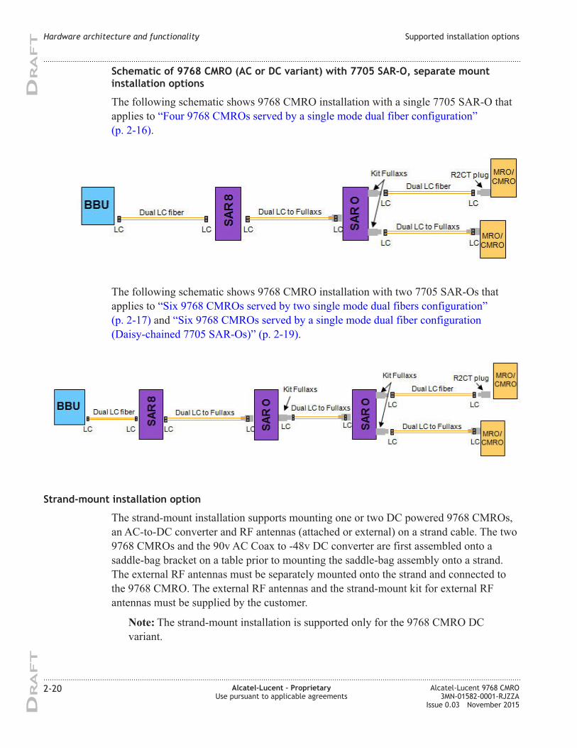
Schematic of 9768 CMRO (AC or DC variant) with 7705 SAR-O, separate mount
installation options
The following schematic shows 9768 CMRO installation with a single 7705 SAR-O that
applies to “Four 9768 CMROs served by a single mode dual fiber configuration”
(p. 2-16).
The following schematic shows 9768 CMRO installation with two 7705 SAR-Os that
applies to “Six 9768 CMROs served by two single mode dual fibers configuration”
(p. 2-17) and “Six 9768 CMROs served by a single mode dual fiber configuration
(Daisy-chained 7705 SAR-Os)” (p. 2-19).
Strand-mount installation option
The strand-mount installation supports mounting one or two DC powered 9768 CMROs,
an AC-to-DC converter and RF antennas (attached or external) on a strand cable. The two
9768 CMROs and the 90v AC Coax to -48v DC converter are first assembled onto a
saddle-bag bracket on a table prior to mounting the saddle-bag assembly onto a strand.
The external RF antennas must be separately mounted onto the strand and connected to
the 9768 CMRO. The external RF antennas and the strand-mount kit for external RF
antennas must be supplied by the customer.
Note: The strand-mount installation is supported only for the 9768 CMRO DC
variant.
Hardware architecture and functionality Supported installation options
....................................................................................................................................................................................................................................
....................................................................................................................................................................................................................................
2-20 Alcatel-Lucent – Proprietary
Use pursuant to applicable agreements
Alcatel-Lucent 9768 CMRO
3MN-01582-0001-RJZZA
Issue 0.03 November 2015
DRA
FT
DRA
FT
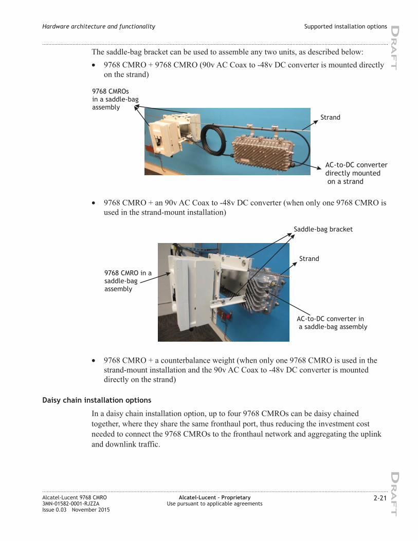
The saddle-bag bracket can be used to assemble any two units, as described below:
• 9768 CMRO + 9768 CMRO (90v AC Coax to -48v DC converter is mounted directly
on the strand)
• 9768 CMRO + an 90v AC Coax to -48v DC converter (when only one 9768 CMRO is
used in the strand-mount installation)
• 9768 CMRO + a counterbalance weight (when only one 9768 CMRO is used in the
strand-mount installation and the 90v AC Coax to -48v DC converter is mounted
directly on the strand)
Daisy chain installation options
In a daisy chain installation option, up to four 9768 CMROs can be daisy chained
together, where they share the same fronthaul port, thus reducing the investment cost
needed to connect the 9768 CMROs to the fronthaul network and aggregating the uplink
and downlink traffic.
9768 CMROs
in a saddle-bag
assembly
AC-to-DC converter
directly mounted
on a strand
Strand
9768 CMRO in a
saddle-bag
assembly
AC-to-DC converter in
a saddle-bag assembly
Saddle-bag bracket
Strand
Hardware architecture and functionality Supported installation options
....................................................................................................................................................................................................................................
....................................................................................................................................................................................................................................
Alcatel-Lucent 9768 CMRO
3MN-01582-0001-RJZZA
Issue 0.03 November 2015
Alcatel-Lucent – Proprietary
Use pursuant to applicable agreements
2-21
DRA
FT
DRA
FT
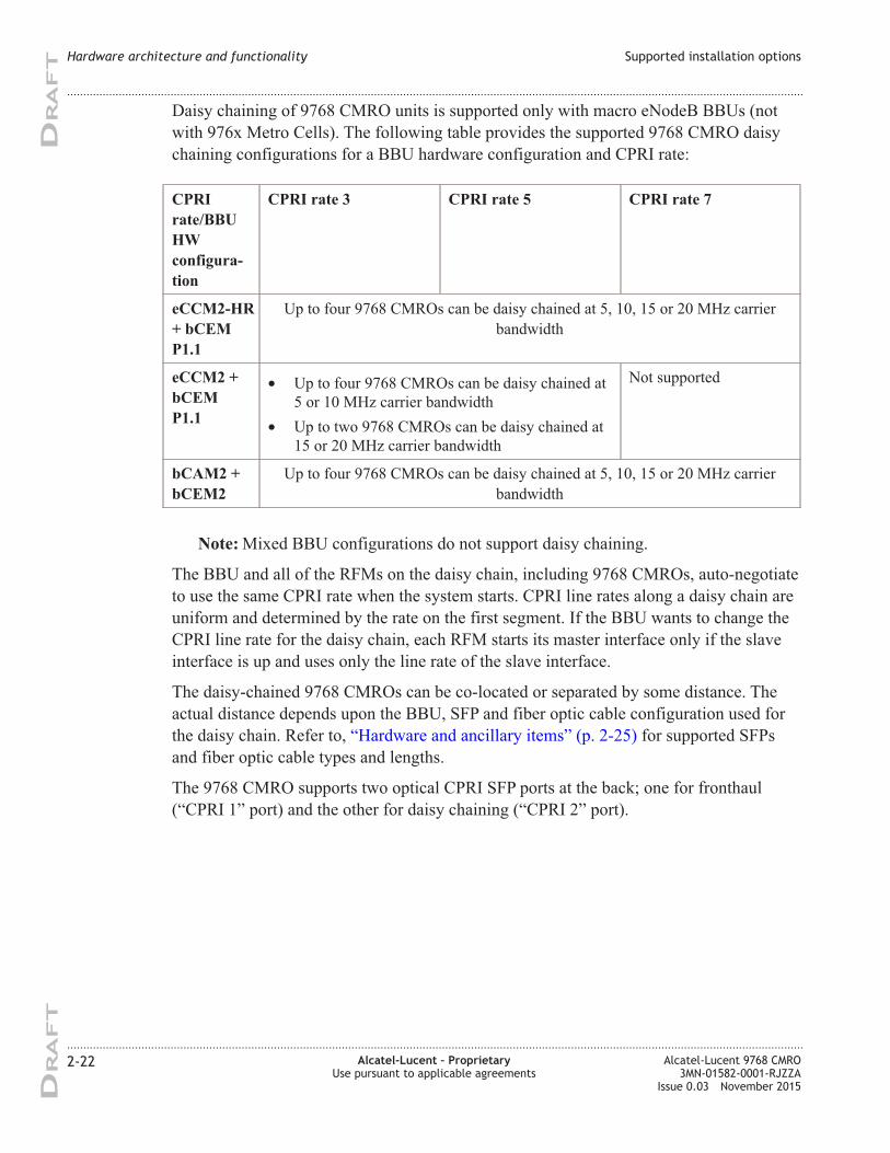
Daisy chaining of 9768 CMRO units is supported only with macro eNodeB BBUs (not
with 976x Metro Cells). The following table provides the supported 9768 CMRO daisy
chaining configurations for a BBU hardware configuration and CPRI rate:
CPRI
rate/BBU
HW
configura-
tion
CPRI rate 3 CPRI rate 5 CPRI rate 7
eCCM2-HR
+ bCEM
P1.1
Up to four 9768 CMROs can be daisy chained at 5, 10, 15 or 20 MHz carrier
bandwidth
eCCM2 +
bCEM
P1.1
• Up to four 9768 CMROs can be daisy chained at
5 or 10 MHz carrier bandwidth
• Up to two 9768 CMROs can be daisy chained at
15 or 20 MHz carrier bandwidth
Not supported
bCAM2 +
bCEM2
Up to four 9768 CMROs can be daisy chained at 5, 10, 15 or 20 MHz carrier
bandwidth
Note: Mixed BBU configurations do not support daisy chaining.
The BBU and all of the RFMs on the daisy chain, including 9768 CMROs, auto-negotiate
to use the same CPRI rate when the system starts. CPRI line rates along a daisy chain are
uniform and determined by the rate on the first segment. If the BBU wants to change the
CPRI line rate for the daisy chain, each RFM starts its master interface only if the slave
interface is up and uses only the line rate of the slave interface.
The daisy-chained 9768 CMROs can be co-located or separated by some distance. The
actual distance depends upon the BBU, SFP and fiber optic cable configuration used for
the daisy chain. Refer to, “Hardware and ancillary items” (p. 2-25) for supported SFPs
and fiber optic cable types and lengths.
The 9768 CMRO supports two optical CPRI SFP ports at the back; one for fronthaul
(“CPRI 1” port) and the other for daisy chaining (“CPRI 2” port).
Hardware architecture and functionality Supported installation options
....................................................................................................................................................................................................................................
....................................................................................................................................................................................................................................
2-22 Alcatel-Lucent – Proprietary
Use pursuant to applicable agreements
Alcatel-Lucent 9768 CMRO
3MN-01582-0001-RJZZA
Issue 0.03 November 2015
DRA
FT
DRA
FT
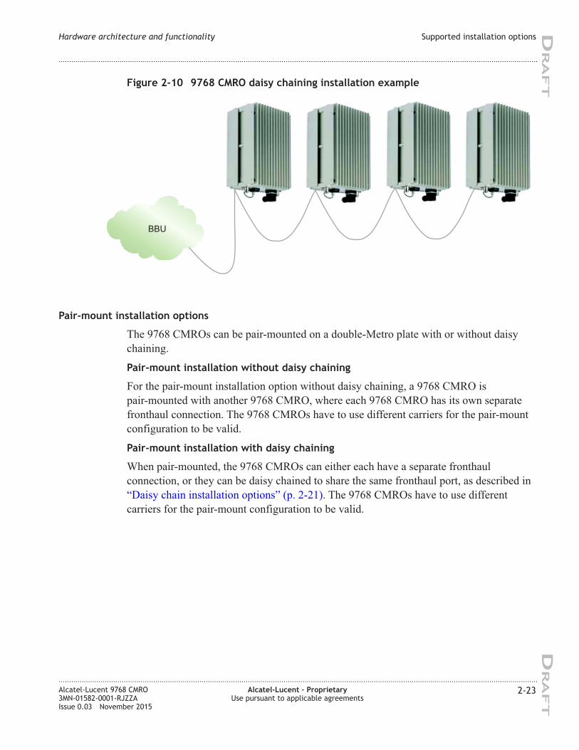
Pair-mount installation options
The 9768 CMROs can be pair-mounted on a double-Metro plate with or without daisy
chaining.
Pair-mount installation without daisy chaining
For the pair-mount installation option without daisy chaining, a 9768 CMRO is
pair-mounted with another 9768 CMRO, where each 9768 CMRO has its own separate
fronthaul connection. The 9768 CMROs have to use different carriers for the pair-mount
configuration to be valid.
Pair-mount installation with daisy chaining
When pair-mounted, the 9768 CMROs can either each have a separate fronthaul
connection, or they can be daisy chained to share the same fronthaul port, as described in
“Daisy chain installation options” (p. 2-21). The 9768 CMROs have to use different
carriers for the pair-mount configuration to be valid.
Figure 2-10 9768 CMRO daisy chaining installation example
BBU
Hardware architecture and functionality Supported installation options
....................................................................................................................................................................................................................................
....................................................................................................................................................................................................................................
Alcatel-Lucent 9768 CMRO
3MN-01582-0001-RJZZA
Issue 0.03 November 2015
Alcatel-Lucent – Proprietary
Use pursuant to applicable agreements
2-23
DRA
FT
DRA
FT
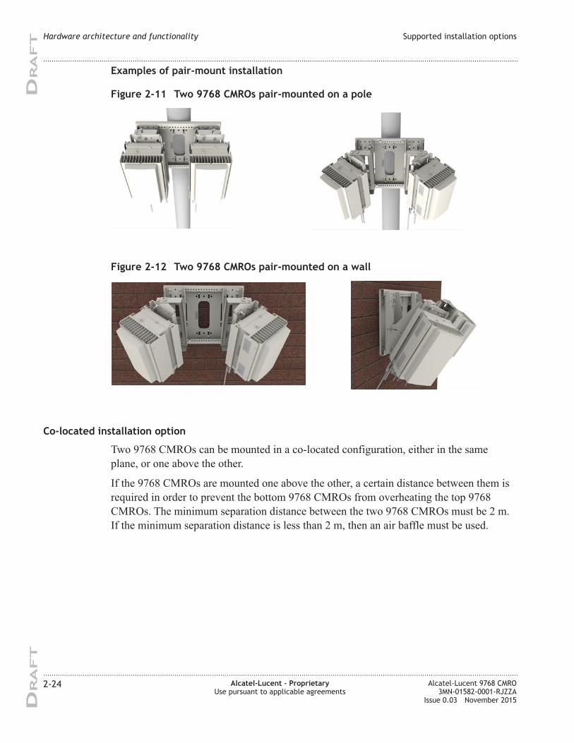
Examples of pair-mount installation
Co-located installation option
Two 9768 CMROs can be mounted in a co-located configuration, either in the same
plane, or one above the other.
If the 9768 CMROs are mounted one above the other, a certain distance between them is
required in order to prevent the bottom 9768 CMROs from overheating the top 9768
CMROs. The minimum separation distance between the two 9768 CMROs must be 2 m.
If the minimum separation distance is less than 2 m, then an air baffle must be used.
Figure 2-11 Two 9768 CMROs pair-mounted on a pole
Figure 2-12 Two 9768 CMROs pair-mounted on a wall
Hardware architecture and functionality Supported installation options
....................................................................................................................................................................................................................................
....................................................................................................................................................................................................................................
2-24 Alcatel-Lucent – Proprietary
Use pursuant to applicable agreements
Alcatel-Lucent 9768 CMRO
3MN-01582-0001-RJZZA
Issue 0.03 November 2015
DRA
FT
DRA
FT
The following table describes the deployment scenarios and whether or not an air baffle is
required:
If... Then...
The minimum separation
distance between the two 9768
CMROs is less than 2 m
An air baffle is required. Mount the air baffle between the two
9768 CMROs.
A minimum separation distance of 50 cm is required between
the two 9768 CMROs to use an air baffle.
Note: The air baffle is customer supplied.
The minimum separation
distance between the 9768
CMROs is 2 m or greater
An air baffle is not required.
Hardware and ancillary items
Overview
The following section lists the Alcatel-Lucent 9768 CMRO base hardware equipment, the
installation kits and ancillary items that can be ordered from Alcatel-Lucent.
9768 CMRO base items
The product packaging contains the following base items:
• 9768 CMRO
• 9768 CMRO mounting frame
• 9768 CMRO basic installation kit
Ancillary items
The following tables list the ancillary items that are available for order from
Alcatel-Lucent in support of the defined equipment installation and configuration options.
Hardware architecture and functionality Supported installation options
....................................................................................................................................................................................................................................
....................................................................................................................................................................................................................................
Alcatel-Lucent 9768 CMRO
3MN-01582-0001-RJZZA
Issue 0.03 November 2015
Alcatel-Lucent – Proprietary
Use pursuant to applicable agreements
2-25
DRA
FT
DRA
FT
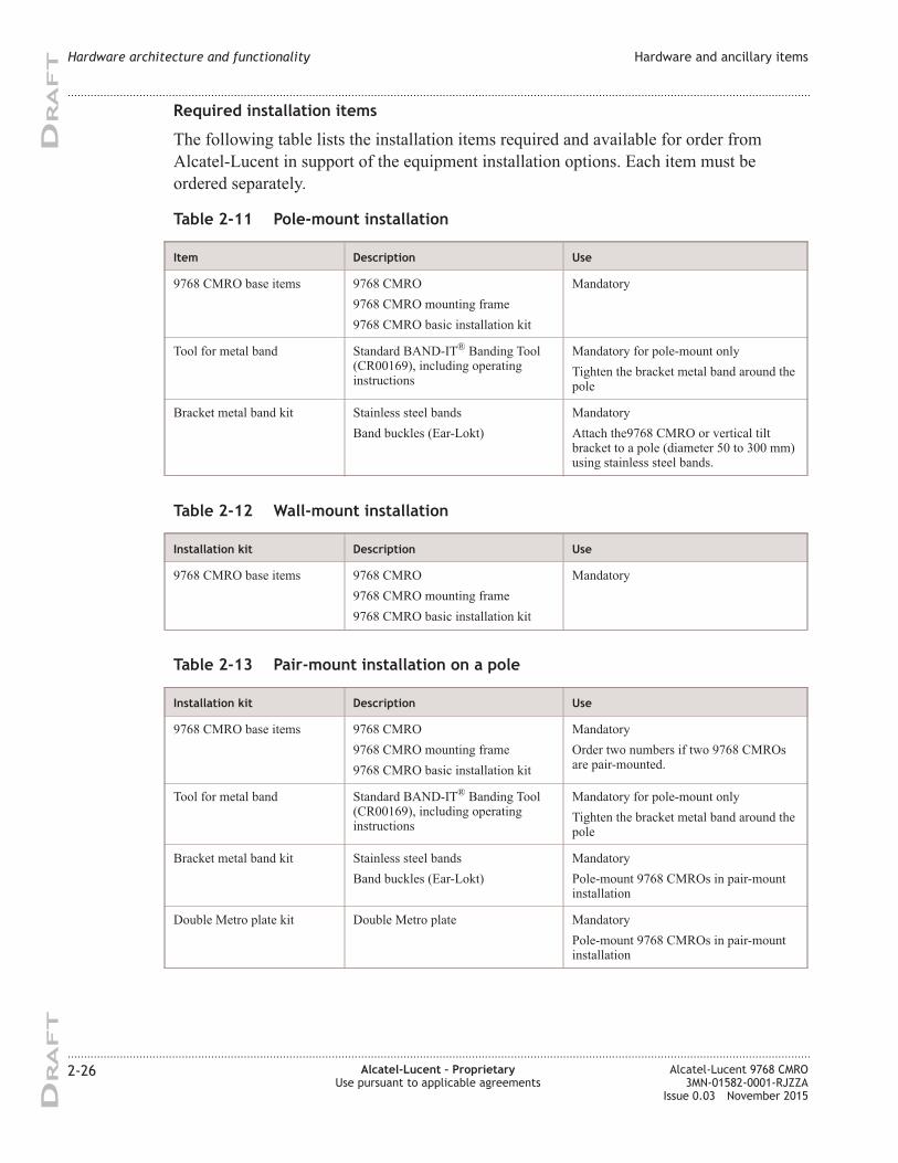
Required installation items
The following table lists the installation items required and available for order from
Alcatel-Lucent in support of the equipment installation options. Each item must be
ordered separately.
Table 2-11 Pole-mount installation
Item Description Use
9768 CMRO base items 9768 CMRO
9768 CMRO mounting frame
9768 CMRO basic installation kit
Mandatory
Tool for metal band Standard BAND-IT®
Banding Tool
(CR00169), including operating
instructions
Mandatory for pole-mount only
Tighten the bracket metal band around the
pole
Bracket metal band kit Stainless steel bands
Band buckles (Ear-Lokt)
Mandatory
Attach the9768 CMRO or vertical tilt
bracket to a pole (diameter 50 to 300 mm)
using stainless steel bands.
Table 2-12 Wall-mount installation
Installation kit Description Use
9768 CMRO base items 9768 CMRO
9768 CMRO mounting frame
9768 CMRO basic installation kit
Mandatory
Table 2-13 Pair-mount installation on a pole
Installation kit Description Use
9768 CMRO base items 9768 CMRO
9768 CMRO mounting frame
9768 CMRO basic installation kit
Mandatory
Order two numbers if two 9768 CMROs
are pair-mounted.
Tool for metal band Standard BAND-IT®
Banding Tool
(CR00169), including operating
instructions
Mandatory for pole-mount only
Tighten the bracket metal band around the
pole
Bracket metal band kit Stainless steel bands
Band buckles (Ear-Lokt)
Mandatory
Pole-mount 9768 CMROs in pair-mount
installation
Double Metro plate kit Double Metro plate Mandatory
Pole-mount 9768 CMROs in pair-mount
installation
Hardware architecture and functionality Hardware and ancillary items
....................................................................................................................................................................................................................................
....................................................................................................................................................................................................................................
2-26 Alcatel-Lucent – Proprietary
Use pursuant to applicable agreements
Alcatel-Lucent 9768 CMRO
3MN-01582-0001-RJZZA
Issue 0.03 November 2015
DRA
FT
DRA
FT
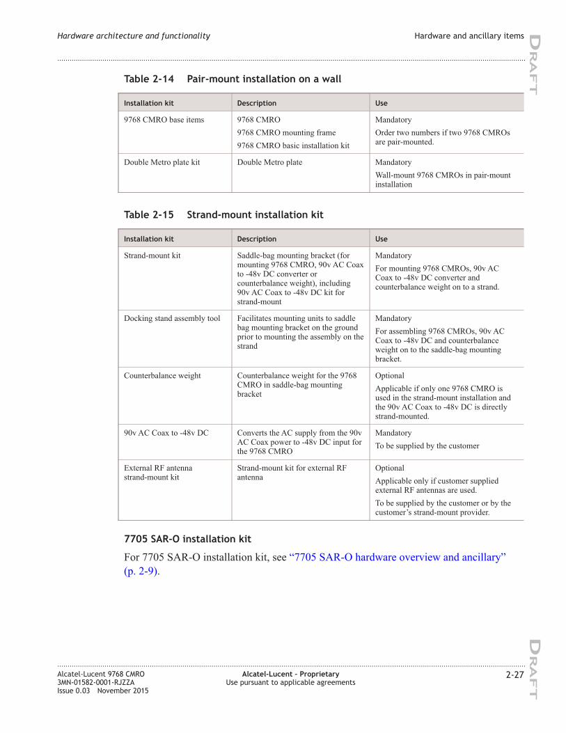
Table 2-14 Pair-mount installation on a wall
Installation kit Description Use
9768 CMRO base items 9768 CMRO
9768 CMRO mounting frame
9768 CMRO basic installation kit
Mandatory
Order two numbers if two 9768 CMROs
are pair-mounted.
Double Metro plate kit Double Metro plate Mandatory
Wall-mount 9768 CMROs in pair-mount
installation
Table 2-15 Strand-mount installation kit
Installation kit Description Use
Strand-mount kit Saddle-bag mounting bracket (for
mounting 9768 CMRO, 90v AC Coax
to -48v DC converter or
counterbalance weight), including
90v AC Coax to -48v DC kit for
strand-mount
Mandatory
For mounting 9768 CMROs, 90v AC
Coax to -48v DC converter and
counterbalance weight on to a strand.
Docking stand assembly tool Facilitates mounting units to saddle
bag mounting bracket on the ground
prior to mounting the assembly on the
strand
Mandatory
For assembling 9768 CMROs, 90v AC
Coax to -48v DC and counterbalance
weight on to the saddle-bag mounting
bracket.
Counterbalance weight Counterbalance weight for the 9768
CMRO in saddle-bag mounting
bracket
Optional
Applicable if only one 9768 CMRO is
used in the strand-mount installation and
the 90v AC Coax to -48v DC is directly
strand-mounted.
90v AC Coax to -48v DC Converts the AC supply from the 90v
AC Coax power to -48v DC input for
the 9768 CMRO
Mandatory
To be supplied by the customer
External RF antenna
strand-mount kit
Strand-mount kit for external RF
antenna
Optional
Applicable only if customer supplied
external RF antennas are used.
To be supplied by the customer or by the
customer’s strand-mount provider.
7705 SAR-O installation kit
For 7705 SAR-O installation kit, see “7705 SAR-O hardware overview and ancillary”
(p. 2-9).
Hardware architecture and functionality Hardware and ancillary items
....................................................................................................................................................................................................................................
....................................................................................................................................................................................................................................
Alcatel-Lucent 9768 CMRO
3MN-01582-0001-RJZZA
Issue 0.03 November 2015
Alcatel-Lucent – Proprietary
Use pursuant to applicable agreements
2-27
DRA
FT
DRA
FT
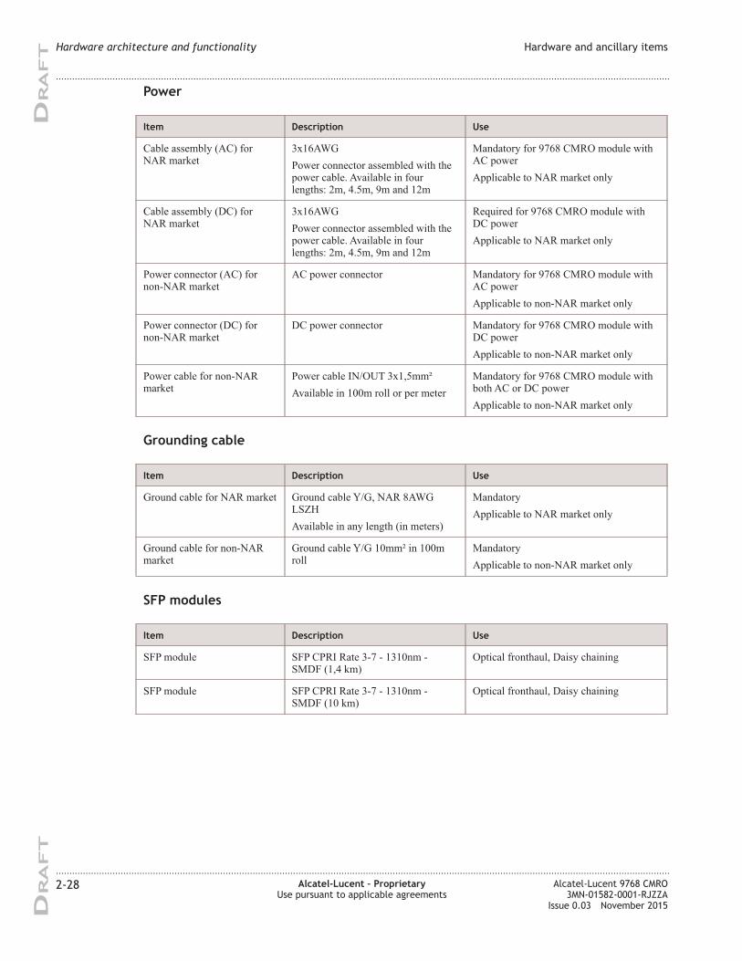
Power
Item Description Use
Cable assembly (AC) for
NAR market
3x16AWG
Power connector assembled with the
power cable. Available in four
lengths: 2m, 4.5m, 9m and 12m
Mandatory for 9768 CMRO module with
AC power
Applicable to NAR market only
Cable assembly (DC) for
NAR market
3x16AWG
Power connector assembled with the
power cable. Available in four
lengths: 2m, 4.5m, 9m and 12m
Required for 9768 CMRO module with
DC power
Applicable to NAR market only
Power connector (AC) for
non-NAR market
AC power connector Mandatory for 9768 CMRO module with
AC power
Applicable to non-NAR market only
Power connector (DC) for
non-NAR market
DC power connector Mandatory for 9768 CMRO module with
DC power
Applicable to non-NAR market only
Power cable for non-NAR
market
Power cable IN/OUT 3x1,5mm²
Available in 100m roll or per meter
Mandatory for 9768 CMRO module with
both AC or DC power
Applicable to non-NAR market only
Grounding cable
Item Description Use
Ground cable for NAR market Ground cable Y/G, NAR 8AWG
LSZH
Available in any length (in meters)
Mandatory
Applicable to NAR market only
Ground cable for non-NAR
market
Ground cable Y/G 10mm² in 100m
roll
Mandatory
Applicable to non-NAR market only
SFP modules
Item Description Use
SFP module SFP CPRI Rate 3-7 - 1310nm -
SMDF (1,4 km)
Optical fronthaul, Daisy chaining
SFP module SFP CPRI Rate 3-7 - 1310nm -
SMDF (10 km)
Optical fronthaul, Daisy chaining
Hardware architecture and functionality Hardware and ancillary items
....................................................................................................................................................................................................................................
....................................................................................................................................................................................................................................
2-28 Alcatel-Lucent – Proprietary
Use pursuant to applicable agreements
Alcatel-Lucent 9768 CMRO
3MN-01582-0001-RJZZA
Issue 0.03 November 2015
DRA
FT
DRA
FT
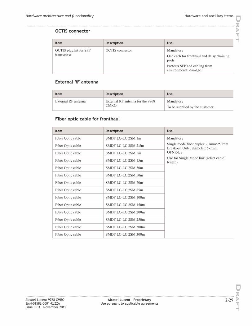
OCTIS connector
Item Description Use
OCTIS plug kit for SFP
transceiver
OCTIS connector Mandatory
One each for fronthaul and daisy chaining
ports
Protects SFP and cabling from
environmental damage.
External RF antenna
Item Description Use
External RF antenna External RF antenna for the 9768
CMRO.
Mandatory
To be supplied by the customer.
Fiber optic cable for fronthaul
Item Description Use
Fiber Optic cable SMDF LC-LC 2SM 1m Mandatory
Single mode fiber duplex. 67mm/250mm
Breakout, Outer diameter: 5-7mm,
OFNR-LS
Use for Single Mode link (select cable
length)
Fiber Optic cable SMDF LC-LC 2SM 2.5m
Fiber Optic cable SMDF LC-LC 2SM 5m
Fiber Optic cable SMDF LC-LC 2SM 15m
Fiber Optic cable SMDF LC-LC 2SM 30m
Fiber Optic cable SMDF LC-LC 2SM 50m
Fiber Optic cable SMDF LC-LC 2SM 70m
Fiber Optic cable SMDF LC-LC 2SM 85m
Fiber Optic cable SMDF LC-LC 2SM 100m
Fiber Optic cable SMDF LC-LC 2SM 150m
Fiber Optic cable SMDF LC-LC 2SM 200m
Fiber Optic cable SMDF LC-LC 2SM 250m
Fiber Optic cable SMDF LC-LC 2SM 300m
Fiber Optic cable SMDF LC-LC 2SM 300m
Hardware architecture and functionality Hardware and ancillary items
....................................................................................................................................................................................................................................
....................................................................................................................................................................................................................................
Alcatel-Lucent 9768 CMRO
3MN-01582-0001-RJZZA
Issue 0.03 November 2015
Alcatel-Lucent – Proprietary
Use pursuant to applicable agreements
2-29
DRA
FT
DRA
FT
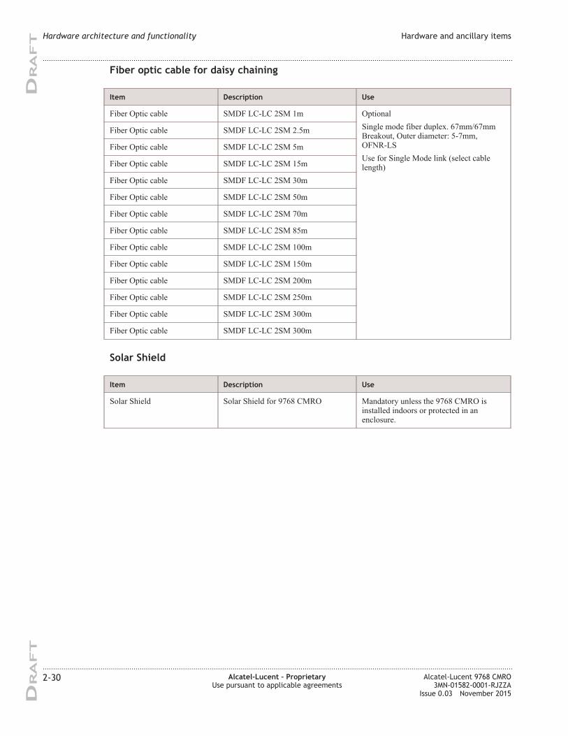
Fiber optic cable for daisy chaining
Item Description Use
Fiber Optic cable SMDF LC-LC 2SM 1m Optional
Single mode fiber duplex. 67mm/67mm
Breakout, Outer diameter: 5-7mm,
OFNR-LS
Use for Single Mode link (select cable
length)
Fiber Optic cable SMDF LC-LC 2SM 2.5m
Fiber Optic cable SMDF LC-LC 2SM 5m
Fiber Optic cable SMDF LC-LC 2SM 15m
Fiber Optic cable SMDF LC-LC 2SM 30m
Fiber Optic cable SMDF LC-LC 2SM 50m
Fiber Optic cable SMDF LC-LC 2SM 70m
Fiber Optic cable SMDF LC-LC 2SM 85m
Fiber Optic cable SMDF LC-LC 2SM 100m
Fiber Optic cable SMDF LC-LC 2SM 150m
Fiber Optic cable SMDF LC-LC 2SM 200m
Fiber Optic cable SMDF LC-LC 2SM 250m
Fiber Optic cable SMDF LC-LC 2SM 300m
Fiber Optic cable SMDF LC-LC 2SM 300m
Solar Shield
Item Description Use
Solar Shield Solar Shield for 9768 CMRO Mandatory unless the 9768 CMRO is
installed indoors or protected in an
enclosure.
Hardware architecture and functionality Hardware and ancillary items
....................................................................................................................................................................................................................................
....................................................................................................................................................................................................................................
2-30 Alcatel-Lucent – Proprietary
Use pursuant to applicable agreements
Alcatel-Lucent 9768 CMRO
3MN-01582-0001-RJZZA
Issue 0.03 November 2015
DRA
FT
DRA
FT
3 3Site selection
Overview
Purpose
This chapter describes basic site preparation requirements for Alcatel-Lucent 9768
Compact Metro Radio Outdoor installation
Contents
Environmental and mechanical specifications 3-2
Spectrum analysis of RF neighborhood 3-3
Site requirements 3-4
Site power requirements (AC) 3-5
Site power requirements (DC) 3-7
9768 CMRO power requirements 3-9
Grounding and lightning protection 3-10
9768 CMRO product grounding 3-11
General antenna cable requirements 3-13
Site requirements for link to baseband processing unit 3-14
Site requirements for a wall mount installation 3-14
Site requirements for a pole mount installation 3-14
Site requirements for strand-mount installation 3-15
...................................................................................................................................................................................................................................
Alcatel-Lucent 9768 CMRO
3MN-01582-0001-RJZZA
Issue 0.03 November 2015
Alcatel-Lucent – Proprietary
Use pursuant to applicable agreements
3-1
DRA
FT
DRA
FT
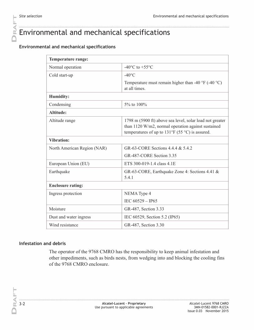
Environmental and mechanical specifications
Environmental and mechanical specifications
Temperature range:
Normal operation -40°C to +55°C
Cold start-up -40°C
Temperature must remain higher than -40 °F (-40 °C)
at all times.
Humidity:
Condensing 5% to 100%
Altitude:
Altitude range 1798 m (5900 ft) above sea level, solar load not greater
than 1120 W/m2, normal operation against sustained
temperatures of up to 131°F (55 °C) is assured.
Vibration:
North American Region (NAR) GR-63-CORE Sections 4.4.4 & 5.4.2
GR-487-CORE Section 3.35
European Union (EU) ETS 300-019-1.4 class 4.1E
Earthquake GR-63-CORE, Earthquake Zone 4: Sections 4.41 &
5.4.1
Enclosure rating:
Ingress protection NEMA Type 4
IEC 60529 – IP65
Moisture GR-487, Section 3.33
Dust and water ingress IEC 60529, Section 5.2 (IP65)
Wind resistance GR-487, Section 3.30
Infestation and debris
The operator of the 9768 CMRO has the responsibility to keep animal infestation and
other impediments, such as birds nests, from wedging into and blocking the cooling fins
of the 9768 CMRO enclosure.
Site selection Environmental and mechanical specifications
....................................................................................................................................................................................................................................
....................................................................................................................................................................................................................................
3-2 Alcatel-Lucent – Proprietary
Use pursuant to applicable agreements
Alcatel-Lucent 9768 CMRO
3MN-01582-0001-RJZZA
Issue 0.03 November 2015
DRA
FT
DRA
FT
Security
The typical deployment of an 9768 CMRO is intended to be up out of human reach.
Nevertheless and especially where this elevation is not achievable, some form of
watchfulness and enforcement to prevent tampering is advised. These considerations may
affect product placement.
Similarly advised is a pre-installation and thereafter occasional spectrum analysis, which
can detect rogue or incidental threats of RF interference that may degrade the 9768
CMRO's communications.
Spectrum analysis of RF neighborhood
Interference
The 9768 CMRO complies with FCC Part 15 Subpart A Class B for immunity to radiated
interference. However, deployments in its unregulated frequency band can be susceptible
to interference from neighboring devices of another carrier or a rogue who is intent on
disrupting the service that 9768 CMROs provide.
Typically, the sector exists within the physical span and secure control of the management
of the venue, but this extent of isolation may not guarantee unimpeded secure
communications. Spectrum analysis during site selection and repeated at intervals during
the deployed service of the 9768 CMRO is recommended.
Another consideration is the extent to which non-radio sources may emit scattered RF
waves that enter the band. Some examples are
• diodes in nearby electronic equipment such as scoreboards, video screens, or flight
tables
• fluorescent lighting.
Site selection Environmental and mechanical specifications
....................................................................................................................................................................................................................................
....................................................................................................................................................................................................................................
Alcatel-Lucent 9768 CMRO
3MN-01582-0001-RJZZA
Issue 0.03 November 2015
Alcatel-Lucent – Proprietary
Use pursuant to applicable agreements
3-3
DRA
FT
DRA
FT
Site requirements
Device placement
Before installing the 9768 CMRO, you should perform a site survey to determine the
optimum use of the equipment and to maximize range, coverage, and network
performance.
The 9768 CMRO is designed to be mounted on poles or walls in a central location within
the public spaces. Clear or open areas (where structures, trees, or hills do not obstruct
radio signals to and from the equipment) will provide better performance than closed or
filled areas.
General requirements
The following general site requirements must be met before the installation of the 9768
CMRO can begin:
• Adequate clearance must be provided for service access
• Power service must be installed
• Back haul facilities must be installed
• Grounding electrode system must be installed
• The environment must comply with stated environment requirements
• Mounting bracket holes must be drilled
• Any necessary cable support structure must be installed
• Where local regulations dictate, cable conduits must be prepared.
Structural requirements
Various building materials and construction methods dictate that equipment must be
fastened to a wall/pole with appropriate mounting hardware. It is the responsibility of the
customer to provide any necessary support material and structures and ensure that the
installation support structure is adequate and compliant with ICC IBC (2012):
International Building Code, and all other national and local codes
Site selection Site requirements
....................................................................................................................................................................................................................................
....................................................................................................................................................................................................................................
3-4 Alcatel-Lucent – Proprietary
Use pursuant to applicable agreements
Alcatel-Lucent 9768 CMRO
3MN-01582-0001-RJZZA
Issue 0.03 November 2015
DRA
FT
DRA
FT
Site power requirements (AC)
Purpose
This section describes the power and grounding requirements that must be considered
when planning site facilities for Alcatel-Lucent installed equipment and products.
General requirements
All power and grounding system wiring, short-circuit (over-current) protection and surge
protection devices must be installed by the appropriately licensed personnel. Installation
must be performed in accordance with national and local electrical codes, for example:
• In the United States:
National Electrical Code, NFPA 70
• In Canada:
Canadian Electrical Code, part I, CSA C22.1
• In other countries:
International Electrotechnical Commission (IEC) 60364, parts 1 through 7
In addition, adherence to all additional requirements mandated by the “country of use” is
the customer's responsibility.
The appropriate power supply ground connections and site equipment ground connections
must be in place before commercial AC power service can be connected to the equipment
installed at the site.
Customer AC power supply
The equipment installed on site must be supported with a customer supplied AC power
service. The AC connection point should be easily accessible by the service team and be
marked as the disconnect device of the equipment.
Note:
• The service board (or load center), circuit breakers and surge protectors devices
are not supplied with the product. They must be ordered and installed as part of
site preparation by the customer.
• All wiring (including grounding) and over-current protection must be installed at
the service panel by suitably trained and licensed personnel and in accordance
with the national and local electrical codes.
• An appropriate earth ground connection is required before commercial power
service can be connected to any equipment at the site.
In the United States and Canada, the branch circuit breaker shall be installed in
accordance with the National Electrical Code, or the Canadian Electrical Code, Part I.
Site selection Site power requirements (AC)
....................................................................................................................................................................................................................................
....................................................................................................................................................................................................................................
Alcatel-Lucent 9768 CMRO
3MN-01582-0001-RJZZA
Issue 0.03 November 2015
Alcatel-Lucent – Proprietary
Use pursuant to applicable agreements
3-5
DRA
FT
DRA
FT
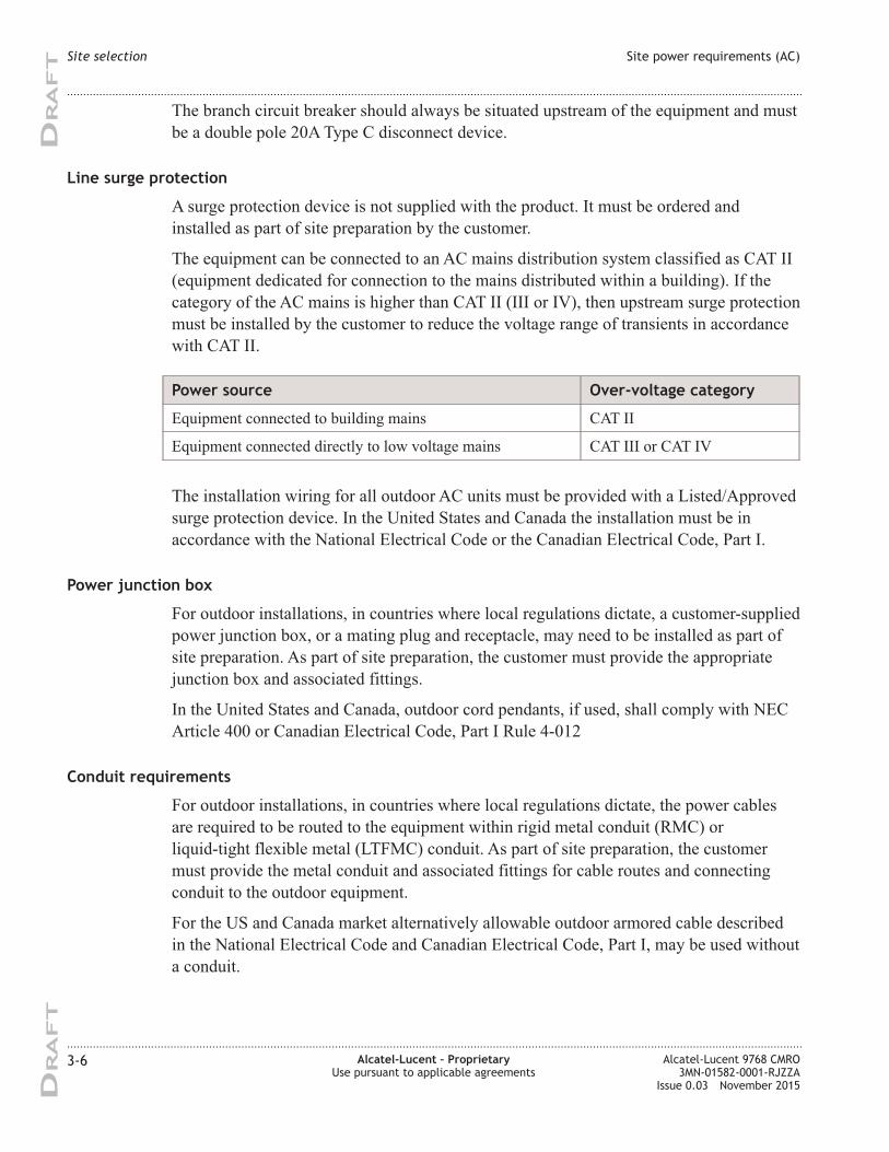
The branch circuit breaker should always be situated upstream of the equipment and must
be a double pole 20A Type C disconnect device.
Line surge protection
A surge protection device is not supplied with the product. It must be ordered and
installed as part of site preparation by the customer.
The equipment can be connected to an AC mains distribution system classified as CAT II
(equipment dedicated for connection to the mains distributed within a building). If the
category of the AC mains is higher than CAT II (III or IV), then upstream surge protection
must be installed by the customer to reduce the voltage range of transients in accordance
with CAT II.
Power source Over-voltage category
Equipment connected to building mains CAT II
Equipment connected directly to low voltage mains CAT III or CAT IV
The installation wiring for all outdoor AC units must be provided with a Listed/Approved
surge protection device. In the United States and Canada the installation must be in
accordance with the National Electrical Code or the Canadian Electrical Code, Part I.
Power junction box
For outdoor installations, in countries where local regulations dictate, a customer-supplied
power junction box, or a mating plug and receptacle, may need to be installed as part of
site preparation. As part of site preparation, the customer must provide the appropriate
junction box and associated fittings.
In the United States and Canada, outdoor cord pendants, if used, shall comply with NEC
Article 400 or Canadian Electrical Code, Part I Rule 4-012
Conduit requirements
For outdoor installations, in countries where local regulations dictate, the power cables
are required to be routed to the equipment within rigid metal conduit (RMC) or
liquid-tight flexible metal (LTFMC) conduit. As part of site preparation, the customer
must provide the metal conduit and associated fittings for cable routes and connecting
conduit to the outdoor equipment.
For the US and Canada market alternatively allowable outdoor armored cable described
in the National Electrical Code and Canadian Electrical Code, Part I, may be used without
a conduit.
Site selection Site power requirements (AC)
....................................................................................................................................................................................................................................
....................................................................................................................................................................................................................................
3-6 Alcatel-Lucent – Proprietary
Use pursuant to applicable agreements
Alcatel-Lucent 9768 CMRO
3MN-01582-0001-RJZZA
Issue 0.03 November 2015
DRA
FT
DRA
FT
Examples:
• Type MC cable, such as Hybriflex cable
• Outdoor tray cable Type TC-ER
Site power requirements (DC)
Purpose
This section describes the power and grounding requirements that must be considered
when planning site facilities for Alcatel-Lucent installed equipment and products.
General requirements
All power and grounding system wiring, short-circuit (over-current) protection and surge
protection devices must be installed by the appropriately licensed personnel. Installation
must be performed in accordance with national and local electrical codes, for example:
• In the United States:
United States National Fire Protection Association (NFPA) 70 and United States
National Electrical Code (NEC)
• In Canada:
Canadian Electrical Code, part I, CSA C22.1
• In other countries:
International Electrotechnical Commission (IEC) 60364, parts 1 through 7
In addition, adherence to all additional requirements mandated by the “country of use” is
the customer's responsibility.
The appropriate power supply ground connections and site equipment ground connections
must be in place before commercial AC power service can be connected to the equipment
installed at the site.
Customer DC power supply
The equipment installed on site must be supported with a customer supplied nominal
-48V DC power service. The DC connection point should be easily accessible by the
service team and be marked as the disconnect device of the equipment.
Site selection Site power requirements (AC)
....................................................................................................................................................................................................................................
....................................................................................................................................................................................................................................
Alcatel-Lucent 9768 CMRO
3MN-01582-0001-RJZZA
Issue 0.03 November 2015
Alcatel-Lucent – Proprietary
Use pursuant to applicable agreements
3-7
DRA
FT
DRA
FT
Note:
• The service board (or load center), circuit breakers and surge protectors devices
are not supplied with the product. They must be ordered and installed as part of
site preparation by the customer.
• All wiring (including grounding) and over-current protection must be installed at
the service panel by suitably trained and licensed personnel and in accordance
with the national and local electrical codes.
• An appropriate earth ground connection is required before commercial power
service can be connected to any equipment at the site.
The branch circuit breaker should always be situated upstream of the equipment and must
be a double pole 20A Type C disconnect device.
Line surge protection
A surge protection device is not supplied with the product. It must be ordered and
installed as part of site preparation by the customer.
Power junction box
For outdoor installations, in countries where local regulations dictate, a customer supplied
power junction box may need to be installed as part of site preparation. As part of site
preparation, the customer must provide the appropriate junction box and associated
fittings.
In the United States and Canada, outdoor cord pendants, if used, shall comply with NEC
Article 400 or Canadian Electrical Code, Part I Rule 4-012.
Conduit requirements
For outdoor installations, in countries where local regulations dictate, the power cables
are required to be routed to the equipment within rigid metal conduit (RMC) or
liquid-tight flexible metal (LTFMC) conduit. As part of site preparation, the customer
must provide the metal conduit and associated fittings for cable routes and connecting
conduit to the outdoor equipment.
For the US and Canada market alternatively allowable outdoor armored cable described
in the National Electrical Code and Canadian Electrical Code, Part I, may be used without
a conduit.
Examples:
• Type MC cable, such as Hybriflex cable
• Outdoor tray cable Type TC-ER
Site selection Site power requirements (DC)
....................................................................................................................................................................................................................................
....................................................................................................................................................................................................................................
3-8 Alcatel-Lucent – Proprietary
Use pursuant to applicable agreements
Alcatel-Lucent 9768 CMRO
3MN-01582-0001-RJZZA
Issue 0.03 November 2015
DRA
FT
DRA
FT
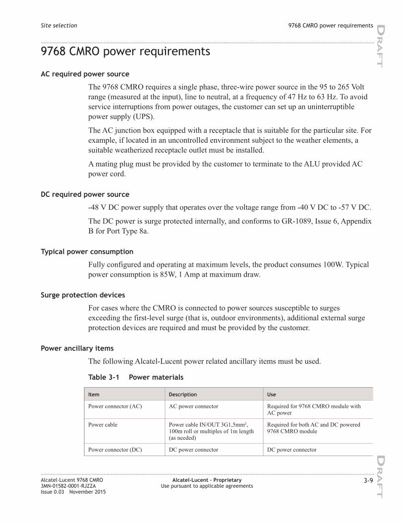
9768 CMRO power requirements
AC required power source
The 9768 CMRO requires a single phase, three-wire power source in the 95 to 265 Volt
range (measured at the input), line to neutral, at a frequency of 47 Hz to 63 Hz. To avoid
service interruptions from power outages, the customer can set up an uninterruptible
power supply (UPS).
The AC junction box equipped with a receptacle that is suitable for the particular site. For
example, if located in an uncontrolled environment subject to the weather elements, a
suitable weatherized receptacle outlet must be installed.
A mating plug must be provided by the customer to terminate to the ALU provided AC
power cord.
DC required power source
-48 V DC power supply that operates over the voltage range from -40 V DC to -57 V DC.
The DC power is surge protected internally, and conforms to GR-1089, Issue 6, Appendix
B for Port Type 8a.
Typical power consumption
Fully configured and operating at maximum levels, the product consumes 100W. Typical
power consumption is 85W, 1 Amp at maximum draw.
Surge protection devices
For cases where the CMRO is connected to power sources susceptible to surges
exceeding the first-level surge (that is, outdoor environments), additional external surge
protection devices are required and must be provided by the customer.
Power ancillary items
The following Alcatel-Lucent power related ancillary items must be used.
Table 3-1 Power materials
Item Description Use
Power connector (AC) AC power connector Required for 9768 CMRO module with
AC power
Power cable Power cable IN/OUT 3G1,5mm²,
100m roll or multiples of 1m length
(as needed)
Required for both AC and DC powered
9768 CMRO module
Power connector (DC) DC power connector DC power connector
Site selection 9768 CMRO power requirements
....................................................................................................................................................................................................................................
....................................................................................................................................................................................................................................
Alcatel-Lucent 9768 CMRO
3MN-01582-0001-RJZZA
Issue 0.03 November 2015
Alcatel-Lucent – Proprietary
Use pursuant to applicable agreements
3-9
DRA
FT
DRA
FT
Grounding and lightning protection
Overview
The primary goal of an earthing system is to assure personnel safety and protection of
installations against damage. Two important phenomena are lightning and power system
faults. These can cause circulation of large currents, which may create hazardous voltages
in the installation.
• For lightning, the task of the earthing system is to provide a path to the soil for
dangerous currents, while maintaining potential differences between any two points of
an installation as low as possible.
• For power system faults, it provides a safe path for fault currents, while also
maintaining potential differences between any two points of an installation as low as
possible.
Codes and standards
Regulatory grounding codes and standards may differ from region to region and country
to country. The grounding/bonding of the installation site and Alcatel-Lucent 9764 Metro
Cell Outdoor must follow national and/or local regulatory codes and standards in
countries and localities where these exist.
Examples of these regulatory codes and standards are:
• National Electric Code (NFPA 70), USA
• Canadian Electrical Code, Part I (CSA C22.1)
• BS 7671 (UK IEE Wiring Regulations, BS 7671
• VDE 0100, Germany
• International Electrotechnical Commission's international standard, 60364
Grounding requirements
The Alcatel-Lucent 9764 Metro Cell Outdoor can be susceptible to lightning surges due to
its association with elevated installation locations. It is therefore imperative that the
equipment and installation site be properly grounded to a reliable and effective grounding
electrode system such that a low impedance path to earth is provided.
For Alcatel-Lucent 9764 Metro Cell Outdoor installations the following grounding system
types are supported:
• TN
In a TN earthing system, one of the points in the generator or transformer is connected
with earth, usually the star point in a three-phase system. The body of the electrical
device is connected with earth via this earth connection at the transformer.
• TT
Site selection Grounding and lightning protection
....................................................................................................................................................................................................................................
....................................................................................................................................................................................................................................
3-10 Alcatel-Lucent – Proprietary
Use pursuant to applicable agreements
Alcatel-Lucent 9768 CMRO
3MN-01582-0001-RJZZA
Issue 0.03 November 2015
DRA
FT
DRA
FT
In a TT earthing system, the protective earth connection of the consumer is provided
by a local connection to earth, independent of any earth connection at the generator.
Important! Where uncertainty exists around the reliability and/or effectiveness of the
main grounding system contact Alcatel-Lucent Technical Support or the appropriate
electrical inspection authority.
In addition the following document can also be used as a general reference for
installation site grounding requirements, Grounding and Lightning Protection
Guidelines for Wireless System Cell Sites, 401-200-115.
Surge protection requirements
Having a good ground alone is not enough to minimize damage due to energy surges.
Commercial power and data facilities are susceptible to lightning surges, switching
transients of power and switching of circuit breakers in the power system under fault
conditions. Therefore power and data facilities must be also be properly protected.
A surge protection device capable of discharging the surge waveforms as defined in IEEE
C62.41 (1991), Recommended Practice on Surge Voltage in Low-Voltage AC Power
Circuits, for Location Category “C3” and “High System Exposure” must be installed in
the power panel board or load center supplying power to the installation site and must be
connected directly to the grounding electrode system. The power panel board or load
center, circuit breakers and surge protector are not supplied with the product. They must
be ordered and installed as part of site preparation by the customer.
It is also strongly recommended that surge protection devices are installed on electrical
data facilities cabling in order to protect against electrical surges that may potentially
cause damage to equipment and the cables if they were not adequately protected.
9768 CMRO product grounding
Overview
This section details the grounding ancillary items and grounding connection points on the
9768 CMRO.
Grounding ancillary items
The following grounding related ancillary items can be ordered from Alcatel-Lucent.
Table 3-2 Grounding materials
Item Description
Grounding cable Green and yellow insulation (100 meter roll)
Site selection Grounding and lightning protection
....................................................................................................................................................................................................................................
....................................................................................................................................................................................................................................
Alcatel-Lucent 9768 CMRO
3MN-01582-0001-RJZZA
Issue 0.03 November 2015
Alcatel-Lucent – Proprietary
Use pursuant to applicable agreements
3-11
DRA
FT
DRA
FT
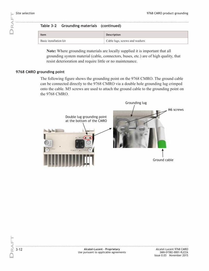
Table 3-2 Grounding materials (continued)
Item Description
Basic installation kit Cable lugs, screws and washers
Note: Where grounding materials are locally supplied it is important that all
grounding system material (cable, connectors, buses, etc.) are of high quality, that
resist deterioration and require little or no maintenance.
9768 CMRO grounding point
The following figure shows the grounding point on the 9768 CMRO. The ground cable
can be connected directly to the 9768 CMRO via a double hole grounding lug crimped
onto the cable. M5 screws are used to attach the ground cable to the grounding point on
the 9768 CMRO.
Double lug grounding point
at the bottom of the CMRO
Grounding lug
M6 screws
Ground cable
Site selection 9768 CMRO product grounding
....................................................................................................................................................................................................................................
....................................................................................................................................................................................................................................
3-12 Alcatel-Lucent – Proprietary
Use pursuant to applicable agreements
Alcatel-Lucent 9768 CMRO
3MN-01582-0001-RJZZA
Issue 0.03 November 2015
DRA
FT
DRA
FT
General antenna cable requirements
General requirements
The appropriate antenna type, cable length and type, and number of antenna jumper
cables should be available at the site for the start of the installation.
The following are general antenna requirements:
• The appropriate Alcatel-Lucent recommended antenna should be used.
• The appropriate Alcatel-Lucent recommended antenna cables should be used.
• All antenna cable runs must be appropriately supported in accordance with the
connector and cable manufacturer's instructions.
• Grounding of the antenna feeder cable outer shield must be performed in accordance
with the ground kit manufacturer's instructions.
• All antenna cable connectors must be at least IP67 rated (IP67 rating requirement, as
defined by IEC 60529, calls for total protection against dust and protection against
submersion in water).
• Antenna and cable sweeps must be performed prior to the start of the installation.
Antenna installation
Antenna installations shall be performed in accordance with all applicable manufacturer's
recommendations, and national laws and regulations.
To ensure correct antenna installation, all necessary calculations and/or field
measurements shall be evaluated for compliance with applicable national laws or
regulations regarding exposure to electromagnetic fields. The antenna manufacturer or
supplier shall deliver all technical data necessary to perform this compliance evaluation
(e.g., antenna gain pattern, antenna dimensions, etc.). Information on the methodology
and results of the compliance evaluation shall be available for inspection by officials of
the governing authorities.
Antenna cable grounding
Grounding of the antenna cable outer shield must be performed in accordance with the
ground kit manufacturer's instructions and as outlined in Grounding and Lightning
Protection Guidelines for Wireless System Cell Sites, 401-200-115.
Site selection General antenna cable requirements
....................................................................................................................................................................................................................................
....................................................................................................................................................................................................................................
Alcatel-Lucent 9768 CMRO
3MN-01582-0001-RJZZA
Issue 0.03 November 2015
Alcatel-Lucent – Proprietary
Use pursuant to applicable agreements
3-13
DRA
FT
DRA
FT
Site requirements for link to baseband processing unit
Distance from 9768 CMRO
The uplink and downlink to the 9768 CMRO are supported for fiber optic cable runs of
not greater than
• 300 m (984 ft) incase of multi-mode
• 15 km (32,810 ft) incase of single-mode
The cable used must support the CPRI Line Bit Rate Option 3.
Site requirements for a wall mount installation
Bracket
The wall-mount bracket that the 9768 CMRO product includes provides sufficient
standoff to dissipate heat and ensure thermal protection of the radio components and the
facility wall or façade.
Weight bearing
The wall or façade and any nonstandard fasteners must be able to sustain at least the 21-lb
(9.53-kg) radio and its 5-lb (2.27-kg) wall-mount hardware, for a total weight of 26 lb
(11.8 kg).
A safety factor of 4 must be observed.
Site requirements for a pole mount installation
Overview
The 9768 CMRO can be easily mounted onto a wooden or metal pole.
The pole-mount bracket to use depends on the diameter of the pole. However, any bracket
used for pole mounting must attach to the pole and to the wall-mount bracket of the 9768
CMRO. The bracket metal band pole-mount kit meets this requirement and is available to
accommodate various diameters (diameter 50 to 300 mm).
The following pole-mount installations are supported:
• The 9768 CMRO banded onto a pole (without the tilt option).
The 9768 CMRO mounting bracket and pole band installation kit is used.
• • The 9768 CMRO attached to the vertical tilt bracket. Vertical tilt bracket is banded
onto a pole.
Site selection Site requirements for link to baseband processing unit
....................................................................................................................................................................................................................................
....................................................................................................................................................................................................................................
3-14 Alcatel-Lucent – Proprietary
Use pursuant to applicable agreements
Alcatel-Lucent 9768 CMRO
3MN-01582-0001-RJZZA
Issue 0.03 November 2015
DRA
FT
DRA
FT
The vertical tilt bracket, 9768 CMRO mounting bracket and pole band installation kit
is used.
Requirements
Attention: The 9768 CMRO must be mounted with the appropriate mounting hardware
suitable for the various supporting structures, building materials and construction
methods. Following a site survey, it is the responsibility of the customer to ensure that:
• The installation support structure is adequate and compliant with ICC IBC (2012):
International Building Code, and all other national and local codes
• The appropriate mounting hardware and any necessary recommended supporting
anchor fixings are used.
Site requirements for strand-mount installation
Overview
The strand-mount installation supports mounting one or two DC powered 9768 CMROs,
an AC-to-DC converter and RF antennas (attached or external) on a strand cable. The two
9768 CMROs and the 90v AC Coax to -48v DC converter are first assembled onto a
saddle-bag bracket on a table prior to mounting the saddle-bag assembly onto a strand.
The external RF antennas must be separately mounted onto the strand and connected to
the 9768 CMRO. The external RF antennas and the strand-mount kit for external RF
antennas must be supplied by the customer.
Note: The strand-mount installation is supported only for the 9768 CMRO DC
variant.
Requirements
To strand-mount the 9768 CMRO DC variant, the following installation items are
required depending on the installation options:
• Strand-mount kit: Saddle-bag mounting bracket (for mounting 9768 CMRO, 90v AC
Coax to -48v DC converter or counterbalance weight), including 90v AC Coax to
-48v DC kit for strand-mount (Mandatory).
• Docking stand and assembly tool: Facilitates mounting units to saddle bag mounting
bracket on the ground prior to mounting the assembly on the strand (Mandatory).
• Counterbalance weight: Counterbalance weight for the 9768 CMRO in saddle-bag
mounting bracket (Optional)
• 90v AC Coax to -48v DC: Converts the AC supply from the 90v AC Coax power to
-48v DC input for the 9768 CMRO (Mandatory).
• External RF antenna strand-mount kit: strand-mount kit for external RF antenna
(Optional).
Site selection Site requirements for a pole mount installation
....................................................................................................................................................................................................................................
....................................................................................................................................................................................................................................
Alcatel-Lucent 9768 CMRO
3MN-01582-0001-RJZZA
Issue 0.03 November 2015
Alcatel-Lucent – Proprietary
Use pursuant to applicable agreements
3-15
DRA
FT
DRA
FT
Prepare site for the strand-mount installation
The following are required to prepare a site for mounting the Alcatel-Lucent 9768
Compact Metro Radio Outdoor onto a strand cable:
• A site survey has been conducted and a location for the device has been selected
• Install backhaul cable runs
• Install power cable runs
• Install RF runs (if antenna connection to remote site)
• Ensure site specific fixing materials are available for strand cable mounting the 9768
CMRO
• Ensure strand cable is adequately grounded
Site selection Site requirements for strand-mount installation
....................................................................................................................................................................................................................................
....................................................................................................................................................................................................................................
3-16 Alcatel-Lucent – Proprietary
Use pursuant to applicable agreements
Alcatel-Lucent 9768 CMRO
3MN-01582-0001-RJZZA
Issue 0.03 November 2015
DRA
FT
DRA
FT
Appendix A: Site survey
checklists
Overview
Purpose
In the following checklists, venue refers to the general area, such as a stadium, enterprise
campus, or airport terminal, at which the equipment will be located, and specific site
refers to the exact position at which the equipment will be installed in that venue.
Contents
SS-1 Venue survey checklist A-1
SS-2 Site survey general checklist A-3
SS-3 Site survey access checklist A-6
SS-4 Site survey conclusion A-7
SS-1 Venue survey checklist
Venue address
Venue
Name
Street address
City, State
...................................................................................................................................................................................................................................
Alcatel-Lucent 9768 CMRO
3MN-01582-0001-RJZZA
Issue 0.03 November 2015
Alcatel-Lucent – Proprietary
Use pursuant to applicable agreements
A-1
DRA
FT
DRA
FT
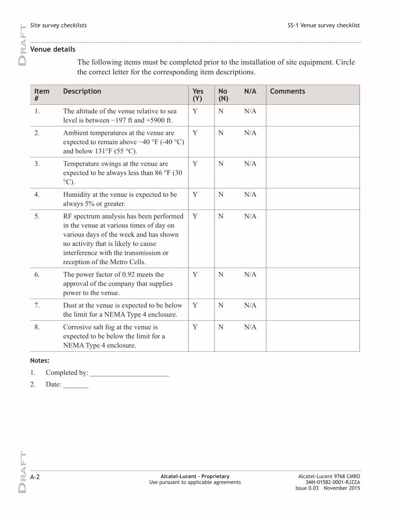
Venue details
The following items must be completed prior to the installation of site equipment. Circle
the correct letter for the corresponding item descriptions.
Item
#
Description Yes
(Y)
No
(N)
N/A Comments
1. The altitude of the venue relative to sea
level is between −197 ft and +5900 ft.
Y N N/A
2. Ambient temperatures at the venue are
expected to remain above −40 °F (-40 °C)
and below 131°F (55 °C).
Y N N/A
3. Temperature swings at the venue are
expected to be always less than 86 °F (30
°C).
Y N N/A
4. Humidity at the venue is expected to be
always 5% or greater.
Y N N/A
5. RF spectrum analysis has been performed
in the venue at various times of day on
various days of the week and has shown
no activity that is likely to cause
interference with the transmission or
reception of the Metro Cells.
Y N N/A
6. The power factor of 0.92 meets the
approval of the company that supplies
power to the venue.
Y N N/A
7. Dust at the venue is expected to be below
the limit for a NEMA Type 4 enclosure.
Y N N/A
8. Corrosive salt fog at the venue is
expected to be below the limit for a
NEMA Type 4 enclosure.
Y N N/A
Notes:
1. Completed by: ______________________
2. Date: _______
Site survey checklists SS-1 Venue survey checklist
....................................................................................................................................................................................................................................
....................................................................................................................................................................................................................................
A-2 Alcatel-Lucent – Proprietary
Use pursuant to applicable agreements
Alcatel-Lucent 9768 CMRO
3MN-01582-0001-RJZZA
Issue 0.03 November 2015
DRA
FT
DRA
FT
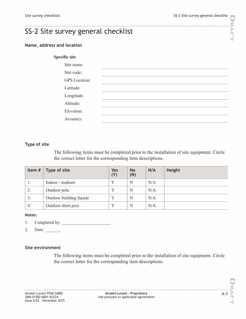
SS-2 Site survey general checklist
Name, address and location
Specific site
Site name:
Site code:
GPS Location:
Latitude:
Longitude:
Altitude:
Elevation:
Accuracy:
Type of site
The following items must be completed prior to the installation of site equipment. Circle
the correct letter for the corresponding item descriptions.
Item # Type of site Yes
(Y)
No
(N)
N/A Height
1. Indoor / stadium Y N N/A
2. Outdoor pole Y N N/A
3. Outdoor building façade Y N N/A
4.` Outdoor short post Y N N/A
Notes:
1. Completed by: ______________________
2. Date: _______
Site environment
The following items must be completed prior to the installation of site equipment. Circle
the correct letter for the corresponding item descriptions.
Site survey checklists SS-2 Site survey general checklist
....................................................................................................................................................................................................................................
....................................................................................................................................................................................................................................
Alcatel-Lucent 9768 CMRO
3MN-01582-0001-RJZZA
Issue 0.03 November 2015
Alcatel-Lucent – Proprietary
Use pursuant to applicable agreements
A-3
DRA
FT
DRA
FT
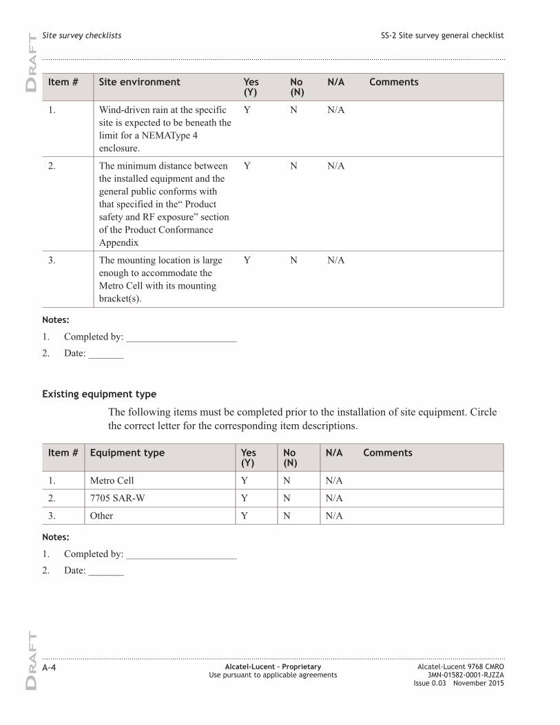
Item # Site environment Yes
(Y)
No
(N)
N/A Comments
1. Wind-driven rain at the specific
site is expected to be beneath the
limit for a NEMAType 4
enclosure.
Y N N/A
2. The minimum distance between
the installed equipment and the
general public conforms with
that specified in the“ Product
safety and RF exposure” section
of the Product Conformance
Appendix
Y N N/A
3. The mounting location is large
enough to accommodate the
Metro Cell with its mounting
bracket(s).
Y N N/A
Notes:
1. Completed by: ______________________
2. Date: _______
Existing equipment type
The following items must be completed prior to the installation of site equipment. Circle
the correct letter for the corresponding item descriptions.
Item # Equipment type Yes
(Y)
No
(N)
N/A Comments
1. Metro Cell Y N N/A
2. 7705 SAR-W Y N N/A
3. Other Y N N/A
Notes:
1. Completed by: ______________________
2. Date: _______
Site survey checklists SS-2 Site survey general checklist
....................................................................................................................................................................................................................................
....................................................................................................................................................................................................................................
A-4 Alcatel-Lucent – Proprietary
Use pursuant to applicable agreements
Alcatel-Lucent 9768 CMRO
3MN-01582-0001-RJZZA
Issue 0.03 November 2015
DRA
FT
DRA
FT
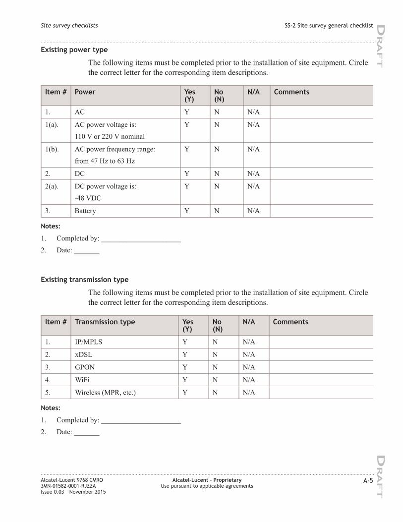
Existing power type
The following items must be completed prior to the installation of site equipment. Circle
the correct letter for the corresponding item descriptions.
Item # Power Yes
(Y)
No
(N)
N/A Comments
1. AC Y N N/A
1(a). AC power voltage is:
110 V or 220 V nominal
Y N N/A
1(b). AC power frequency range:
from 47 Hz to 63 Hz
Y N N/A
2. DC Y N N/A
2(a). DC power voltage is:
-48 VDC
Y N N/A
3. Battery Y N N/A
Notes:
1. Completed by: ______________________
2. Date: _______
Existing transmission type
The following items must be completed prior to the installation of site equipment. Circle
the correct letter for the corresponding item descriptions.
Item # Transmission type Yes
(Y)
No
(N)
N/A Comments
1. IP/MPLS Y N N/A
2. xDSL Y N N/A
3. GPON Y N N/A
4. WiFi Y N N/A
5. Wireless (MPR, etc.) Y N N/A
Notes:
1. Completed by: ______________________
2. Date: _______
Site survey checklists SS-2 Site survey general checklist
....................................................................................................................................................................................................................................
....................................................................................................................................................................................................................................
Alcatel-Lucent 9768 CMRO
3MN-01582-0001-RJZZA
Issue 0.03 November 2015
Alcatel-Lucent – Proprietary
Use pursuant to applicable agreements
A-5
DRA
FT
DRA
FT
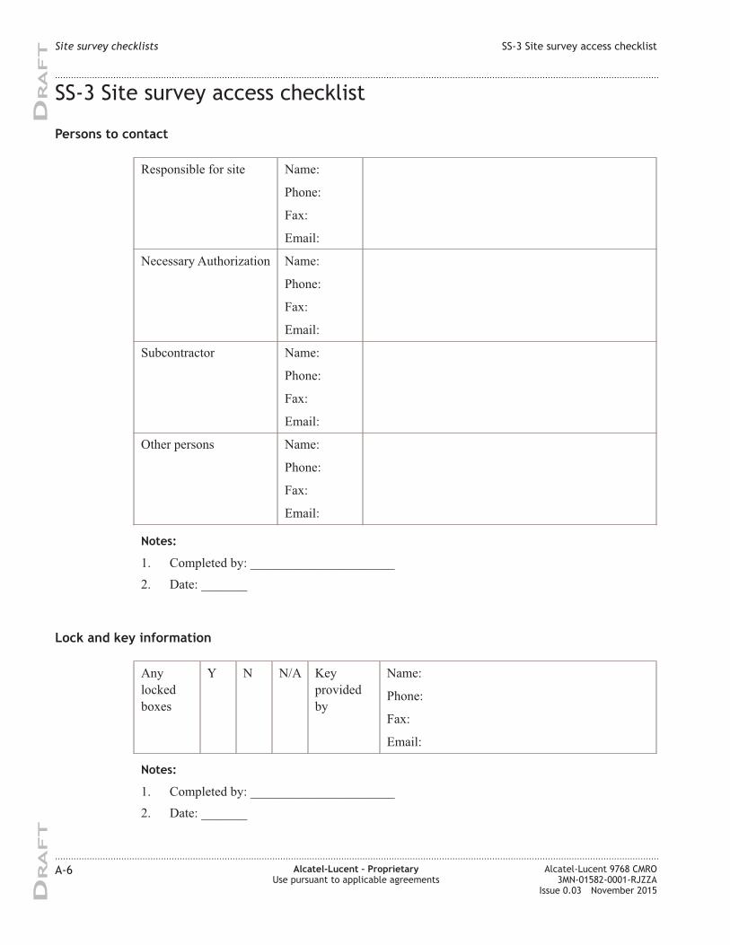
SS-3 Site survey access checklist
Persons to contact
Responsible for site Name:
Phone:
Fax:
Email:
Necessary Authorization Name:
Phone:
Fax:
Email:
Subcontractor Name:
Phone:
Fax:
Email:
Other persons Name:
Phone:
Fax:
Email:
Notes:
1. Completed by: ______________________
2. Date: _______
Lock and key information
Any
locked
boxes
Y N N/A Key
provided
by
Name:
Phone:
Fax:
Email:
Notes:
1. Completed by: ______________________
2. Date: _______
Site survey checklists SS-3 Site survey access checklist
....................................................................................................................................................................................................................................
....................................................................................................................................................................................................................................
A-6 Alcatel-Lucent – Proprietary
Use pursuant to applicable agreements
Alcatel-Lucent 9768 CMRO
3MN-01582-0001-RJZZA
Issue 0.03 November 2015
DRA
FT
DRA
FT
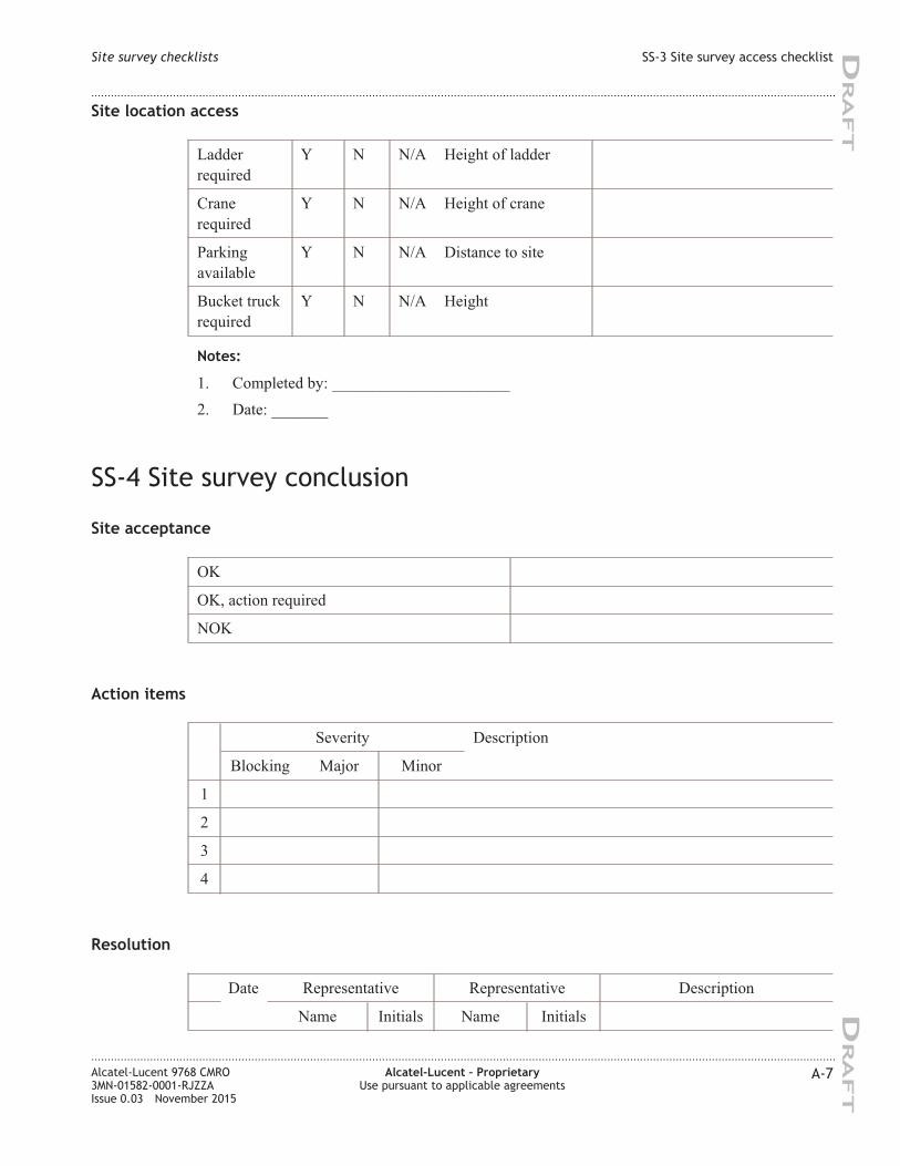
Site location access
Ladder
required
Y N N/A Height of ladder
Crane
required
Y N N/A Height of crane
Parking
available
Y N N/A Distance to site
Bucket truck
required
Y N N/A Height
Notes:
1. Completed by: ______________________
2. Date: _______
SS-4 Site survey conclusion
Site acceptance
OK
OK, action required
NOK
Action items
Severity Description
Blocking Major Minor
1
2
3
4
Resolution
Date Representative Representative Description
Name Initials Name Initials
Site survey checklists SS-3 Site survey access checklist
....................................................................................................................................................................................................................................
....................................................................................................................................................................................................................................
Alcatel-Lucent 9768 CMRO
3MN-01582-0001-RJZZA
Issue 0.03 November 2015
Alcatel-Lucent – Proprietary
Use pursuant to applicable agreements
A-7
DRA
FT
DRA
FT
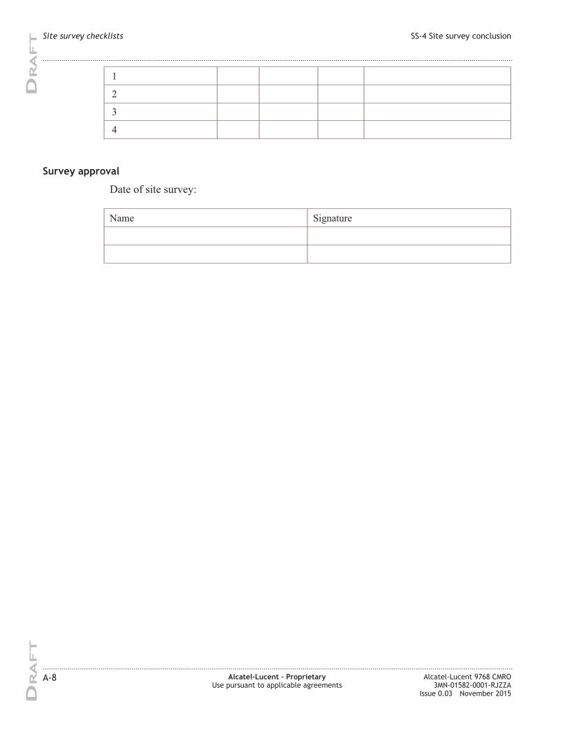
1
2
3
4
Survey approval
Date of site survey:
Name Signature
Site survey checklists SS-4 Site survey conclusion
....................................................................................................................................................................................................................................
....................................................................................................................................................................................................................................
A-8 Alcatel-Lucent – Proprietary
Use pursuant to applicable agreements
Alcatel-Lucent 9768 CMRO
3MN-01582-0001-RJZZA
Issue 0.03 November 2015
DRA
FT
DRA
FT
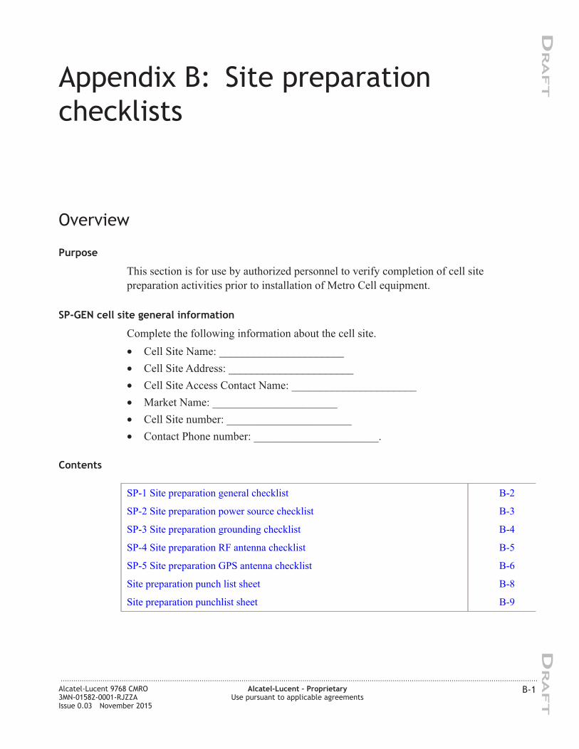
Appendix B: Site preparation
checklists
Overview
Purpose
This section is for use by authorized personnel to verify completion of cell site
preparation activities prior to installation of Metro Cell equipment.
SP-GEN cell site general information
Complete the following information about the cell site.
• Cell Site Name: ______________________
• Cell Site Address: ______________________
• Cell Site Access Contact Name: ______________________
• Market Name: ______________________
• Cell Site number: ______________________
• Contact Phone number: ______________________.
Contents
SP-1 Site preparation general checklist B-2
SP-2 Site preparation power source checklist B-3
SP-3 Site preparation grounding checklist B-4
SP-4 Site preparation RF antenna checklist B-5
SP-5 Site preparation GPS antenna checklist B-6
Site preparation punch list sheet B-8
Site preparation punchlist sheet B-9
...................................................................................................................................................................................................................................
Alcatel-Lucent 9768 CMRO
3MN-01582-0001-RJZZA
Issue 0.03 November 2015
Alcatel-Lucent – Proprietary
Use pursuant to applicable agreements
B-1
DRA
FT
DRA
FT
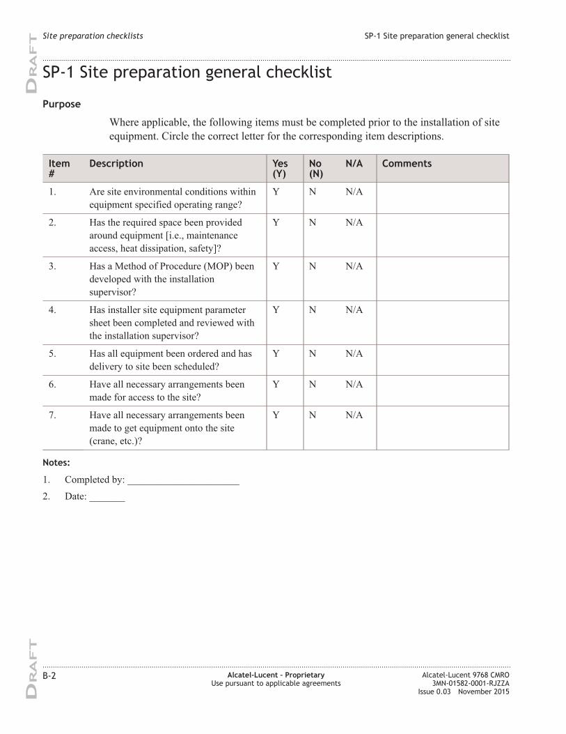
SP-1 Site preparation general checklist
Purpose
Where applicable, the following items must be completed prior to the installation of site
equipment. Circle the correct letter for the corresponding item descriptions.
Item
#
Description Yes
(Y)
No
(N)
N/A Comments
1. Are site environmental conditions within
equipment specified operating range?
Y N N/A
2. Has the required space been provided
around equipment [i.e., maintenance
access, heat dissipation, safety]?
Y N N/A
3. Has a Method of Procedure (MOP) been
developed with the installation
supervisor?
Y N N/A
4. Has installer site equipment parameter
sheet been completed and reviewed with
the installation supervisor?
Y N N/A
5. Has all equipment been ordered and has
delivery to site been scheduled?
Y N N/A
6. Have all necessary arrangements been
made for access to the site?
Y N N/A
7. Have all necessary arrangements been
made to get equipment onto the site
(crane, etc.)?
Y N N/A
Notes:
1. Completed by: ______________________
2. Date: _______
Site preparation checklists SP-1 Site preparation general checklist
....................................................................................................................................................................................................................................
....................................................................................................................................................................................................................................
B-2 Alcatel-Lucent – Proprietary
Use pursuant to applicable agreements
Alcatel-Lucent 9768 CMRO
3MN-01582-0001-RJZZA
Issue 0.03 November 2015
DRA
FT
DRA
FT
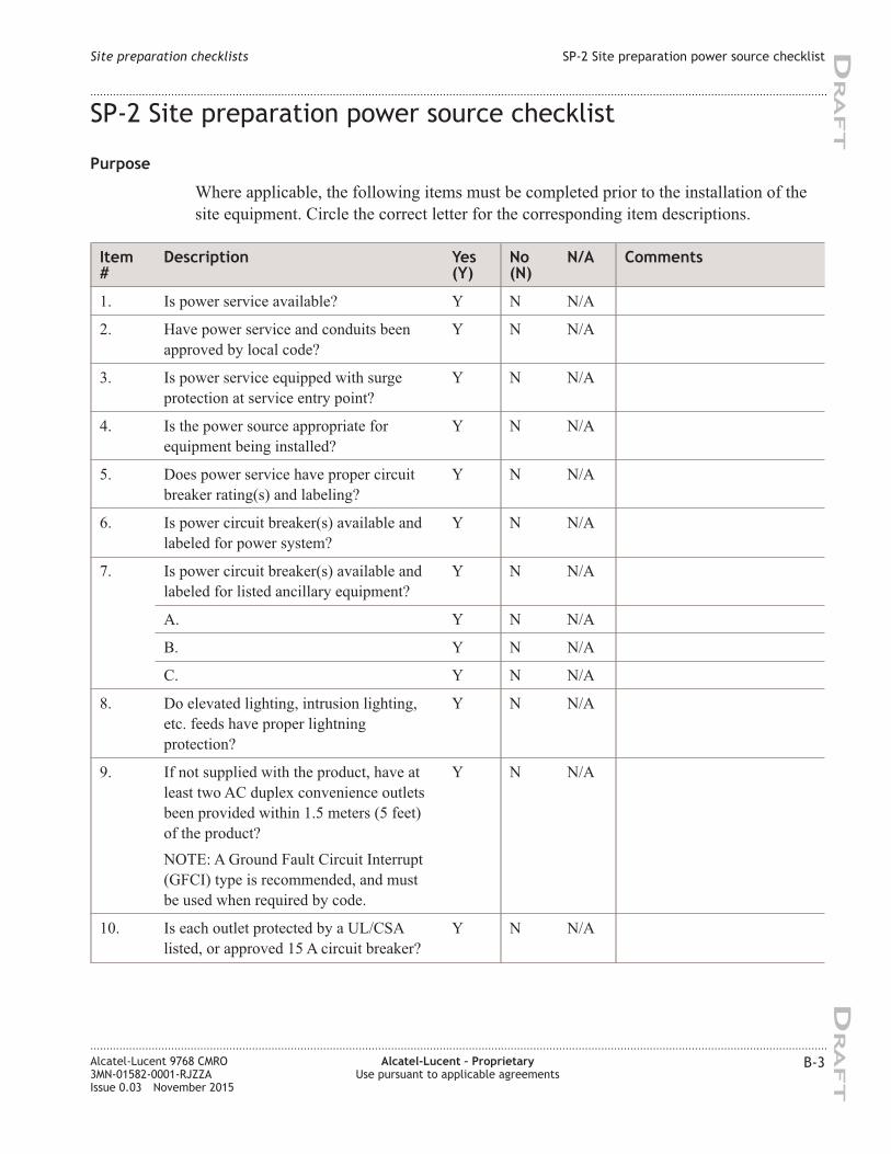
SP-2 Site preparation power source checklist
Purpose
Where applicable, the following items must be completed prior to the installation of the
site equipment. Circle the correct letter for the corresponding item descriptions.
Item
#
Description Yes
(Y)
No
(N)
N/A Comments
1. Is power service available? Y N N/A
2. Have power service and conduits been
approved by local code?
Y N N/A
3. Is power service equipped with surge
protection at service entry point?
Y N N/A
4. Is the power source appropriate for
equipment being installed?
Y N N/A
5. Does power service have proper circuit
breaker rating(s) and labeling?
Y N N/A
6. Is power circuit breaker(s) available and
labeled for power system?
Y N N/A
7. Is power circuit breaker(s) available and
labeled for listed ancillary equipment?
Y N N/A
A. Y N N/A
B. Y N N/A
C. Y N N/A
8. Do elevated lighting, intrusion lighting,
etc. feeds have proper lightning
protection?
Y N N/A
9. If not supplied with the product, have at
least two AC duplex convenience outlets
been provided within 1.5 meters (5 feet)
of the product?
NOTE: A Ground Fault Circuit Interrupt
(GFCI) type is recommended, and must
be used when required by code.
Y N N/A
10. Is each outlet protected by a UL/CSA
listed, or approved 15 A circuit breaker?
Y N N/A
Site preparation checklists SP-2 Site preparation power source checklist
....................................................................................................................................................................................................................................
....................................................................................................................................................................................................................................
Alcatel-Lucent 9768 CMRO
3MN-01582-0001-RJZZA
Issue 0.03 November 2015
Alcatel-Lucent – Proprietary
Use pursuant to applicable agreements
B-3
DRA
FT
DRA
FT
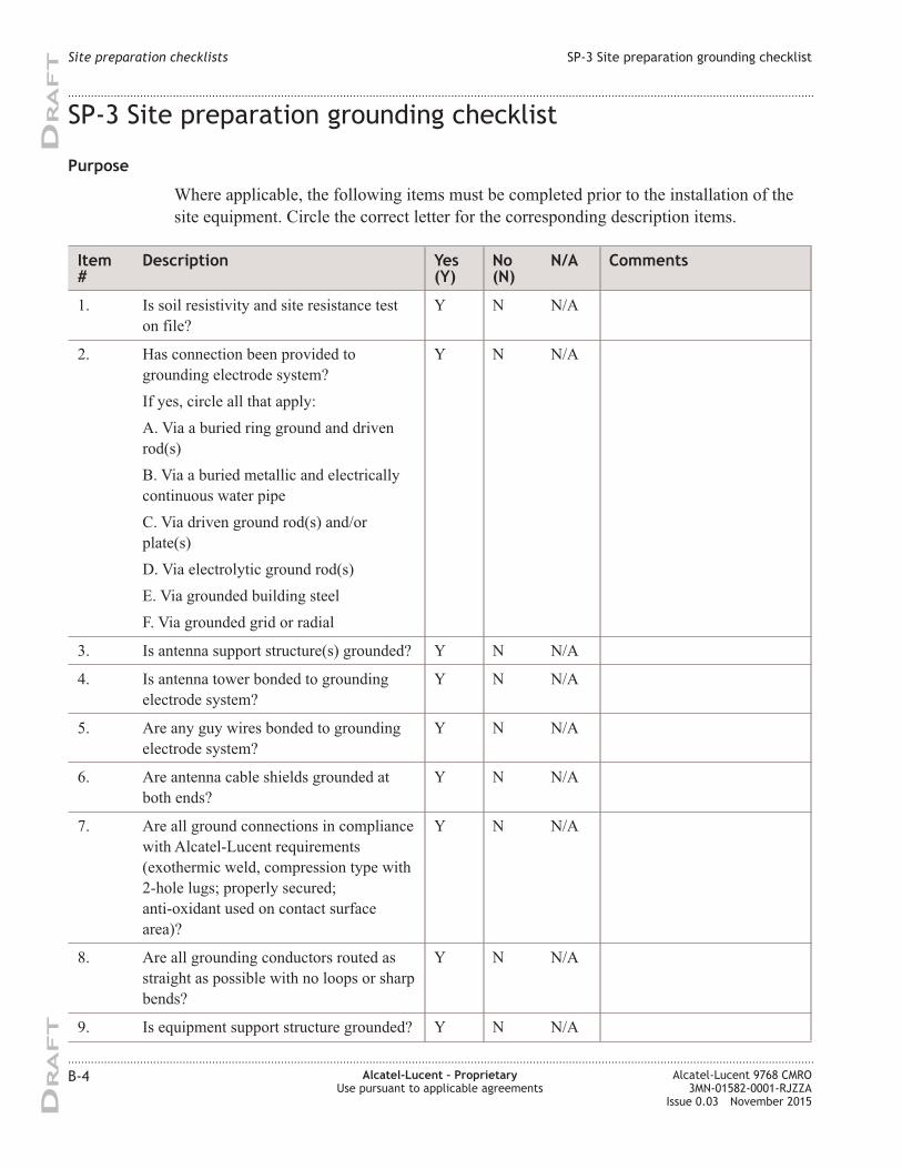
SP-3 Site preparation grounding checklist
Purpose
Where applicable, the following items must be completed prior to the installation of the
site equipment. Circle the correct letter for the corresponding description items.
Item
#
Description Yes
(Y)
No
(N)
N/A Comments
1. Is soil resistivity and site resistance test
on file?
Y N N/A
2. Has connection been provided to
grounding electrode system?
If yes, circle all that apply:
A. Via a buried ring ground and driven
rod(s)
B. Via a buried metallic and electrically
continuous water pipe
C. Via driven ground rod(s) and/or
plate(s)
D. Via electrolytic ground rod(s)
E. Via grounded building steel
F. Via grounded grid or radial
Y N N/A
3. Is antenna support structure(s) grounded? Y N N/A
4. Is antenna tower bonded to grounding
electrode system?
Y N N/A
5. Are any guy wires bonded to grounding
electrode system?
Y N N/A
6. Are antenna cable shields grounded at
both ends?
Y N N/A
7. Are all ground connections in compliance
with Alcatel-Lucent requirements
(exothermic weld, compression type with
2-hole lugs; properly secured;
anti-oxidant used on contact surface
area)?
Y N N/A
8. Are all grounding conductors routed as
straight as possible with no loops or sharp
bends?
Y N N/A
9. Is equipment support structure grounded? Y N N/A
Site preparation checklists SP-3 Site preparation grounding checklist
....................................................................................................................................................................................................................................
....................................................................................................................................................................................................................................
B-4 Alcatel-Lucent – Proprietary
Use pursuant to applicable agreements
Alcatel-Lucent 9768 CMRO
3MN-01582-0001-RJZZA
Issue 0.03 November 2015
DRA
FT
DRA
FT
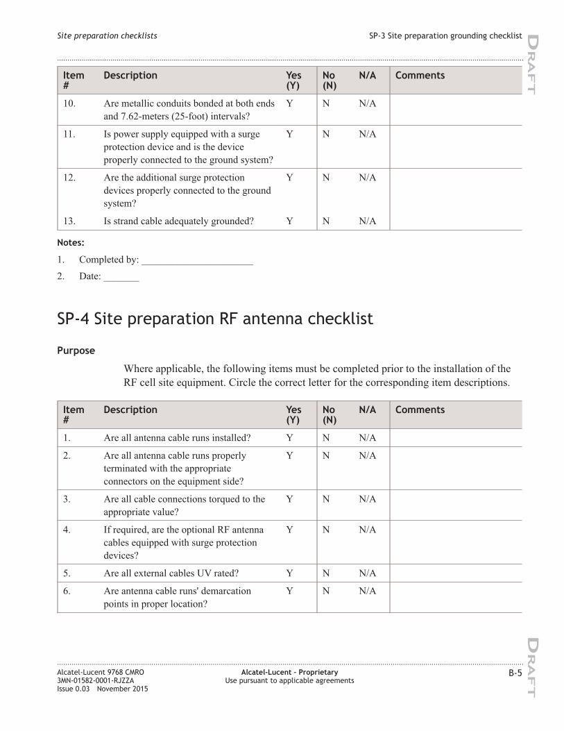
Item
#
Description Yes
(Y)
No
(N)
N/A Comments
10. Are metallic conduits bonded at both ends
and 7.62-meters (25-foot) intervals?
Y N N/A
11. Is power supply equipped with a surge
protection device and is the device
properly connected to the ground system?
Y N N/A
12. Are the additional surge protection
devices properly connected to the ground
system?
Y N N/A
13. Is strand cable adequately grounded? Y N N/A
Notes:
1. Completed by: ______________________
2. Date: _______
SP-4 Site preparation RF antenna checklist
Purpose
Where applicable, the following items must be completed prior to the installation of the
RF cell site equipment. Circle the correct letter for the corresponding item descriptions.
Item
#
Description Yes
(Y)
No
(N)
N/A Comments
1. Are all antenna cable runs installed? Y N N/A
2. Are all antenna cable runs properly
terminated with the appropriate
connectors on the equipment side?
Y N N/A
3. Are all cable connections torqued to the
appropriate value?
Y N N/A
4. If required, are the optional RF antenna
cables equipped with surge protection
devices?
Y N N/A
5. Are all external cables UV rated? Y N N/A
6. Are antenna cable runs' demarcation
points in proper location?
Y N N/A
Site preparation checklists SP-3 Site preparation grounding checklist
....................................................................................................................................................................................................................................
....................................................................................................................................................................................................................................
Alcatel-Lucent 9768 CMRO
3MN-01582-0001-RJZZA
Issue 0.03 November 2015
Alcatel-Lucent – Proprietary
Use pursuant to applicable agreements
B-5
DRA
FT
DRA
FT
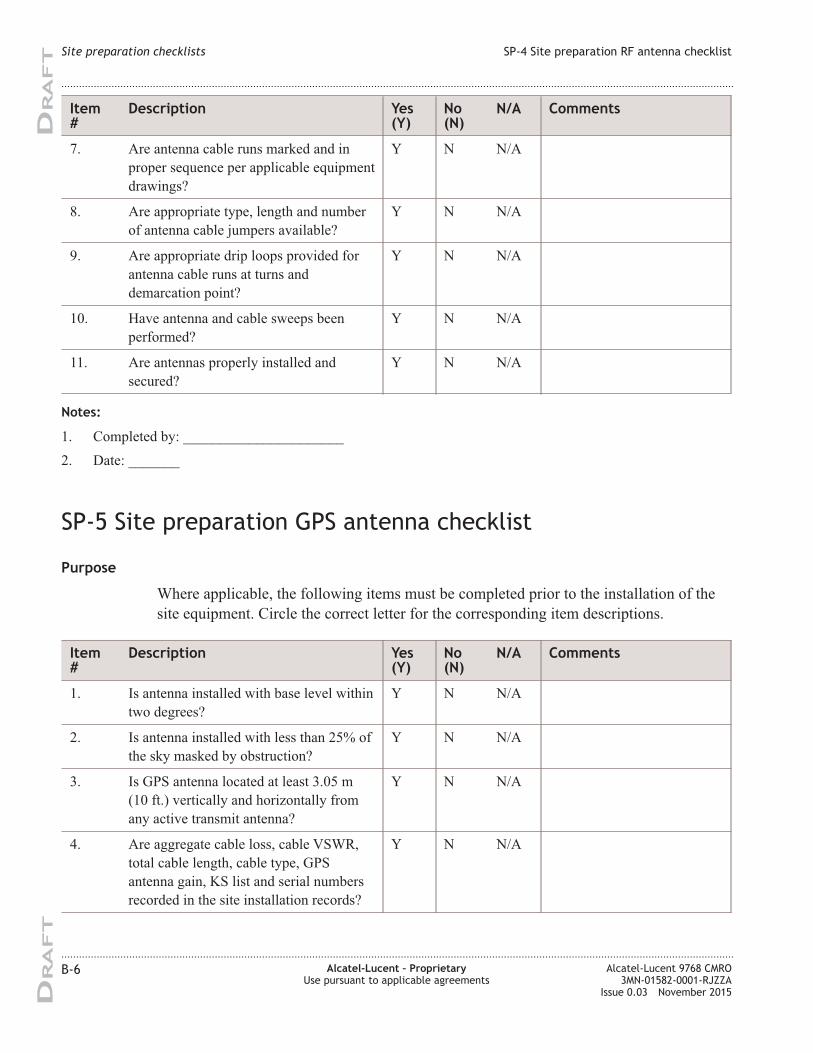
Item
#
Description Yes
(Y)
No
(N)
N/A Comments
7. Are antenna cable runs marked and in
proper sequence per applicable equipment
drawings?
Y N N/A
8. Are appropriate type, length and number
of antenna cable jumpers available?
Y N N/A
9. Are appropriate drip loops provided for
antenna cable runs at turns and
demarcation point?
Y N N/A
10. Have antenna and cable sweeps been
performed?
Y N N/A
11. Are antennas properly installed and
secured?
Y N N/A
Notes:
1. Completed by: ______________________
2. Date: _______
SP-5 Site preparation GPS antenna checklist
Purpose
Where applicable, the following items must be completed prior to the installation of the
site equipment. Circle the correct letter for the corresponding item descriptions.
Item
#
Description Yes
(Y)
No
(N)
N/A Comments
1. Is antenna installed with base level within
two degrees?
Y N N/A
2. Is antenna installed with less than 25% of
the sky masked by obstruction?
Y N N/A
3. Is GPS antenna located at least 3.05 m
(10 ft.) vertically and horizontally from
any active transmit antenna?
Y N N/A
4. Are aggregate cable loss, cable VSWR,
total cable length, cable type, GPS
antenna gain, KS list and serial numbers
recorded in the site installation records?
Y N N/A
Site preparation checklists SP-4 Site preparation RF antenna checklist
....................................................................................................................................................................................................................................
....................................................................................................................................................................................................................................
B-6 Alcatel-Lucent – Proprietary
Use pursuant to applicable agreements
Alcatel-Lucent 9768 CMRO
3MN-01582-0001-RJZZA
Issue 0.03 November 2015
DRA
FT
DRA
FT
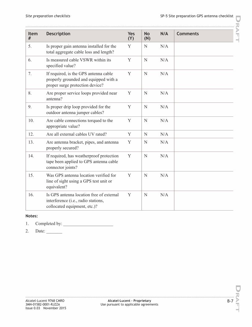
Item
#
Description Yes
(Y)
No
(N)
N/A Comments
5. Is proper gain antenna installed for the
total aggregate cable loss and length?
Y N N/A
6. Is measured cable VSWR within its
specified value?
Y N N/A
7. If required, is the GPS antenna cable
properly grounded and equipped with a
proper surge protection device?
Y N N/A
8. Are proper service loops provided near
antenna?
Y N N/A
9. Is proper drip loop provided for the
outdoor antenna jumper cables?
Y N N/A
10. Are cable connections torqued to the
appropriate value?
Y N N/A
12. Are all external cables UV rated? Y N N/A
13. Are antenna bracket, pipes, and antenna
properly secured?
Y N N/A
14. If required, has weatherproof protection
tape been applied to GPS antenna cable
connector joints?
Y N N/A
15. Was GPS antenna location verified for
line of sight using a GPS test unit or
equivalent?
Y N N/A
16. Is GPS antenna location free of external
interference (i.e., radio stations,
collocated equipment, etc.)?
Y N N/A
Notes:
1. Completed by: ______________________
2. Date: _______
Site preparation checklists SP-5 Site preparation GPS antenna checklist
....................................................................................................................................................................................................................................
....................................................................................................................................................................................................................................
Alcatel-Lucent 9768 CMRO
3MN-01582-0001-RJZZA
Issue 0.03 November 2015
Alcatel-Lucent – Proprietary
Use pursuant to applicable agreements
B-7
DRA
FT
DRA
FT

Site preparation punch list sheet
Purpose
The following punch list is used to track any outstanding site preparation items.
Item # Comment/Description Severity (1/2/3) Corrective Action Required
(Y/N) Completed Date
Notes:
1. Equipment installation cannot occur until outage is rectified and will void warranty or potentially cause
personal injury.
2. Equipment installation can occur but issue must be rectified prior to handoff to customer or service turn-up
so that the warranty is not voided.
3. Equipment installation, handoff to customer, or service turn-up can occur but not per Alcatel-Lucent
recommendations.
4. Inspection Checklist Completion Sign-Off (complete below)
5. Was the punchlist continuation sheet on the next page used? Yes or No
6. Inspector's Name: ______________________
7. Inspector's Signature: _____________________ Date: _________
Site preparation checklists Site preparation punch list sheet
....................................................................................................................................................................................................................................
....................................................................................................................................................................................................................................
B-8 Alcatel-Lucent – Proprietary
Use pursuant to applicable agreements
Alcatel-Lucent 9768 CMRO
3MN-01582-0001-RJZZA
Issue 0.03 November 2015
DRA
FT
DRA
FT
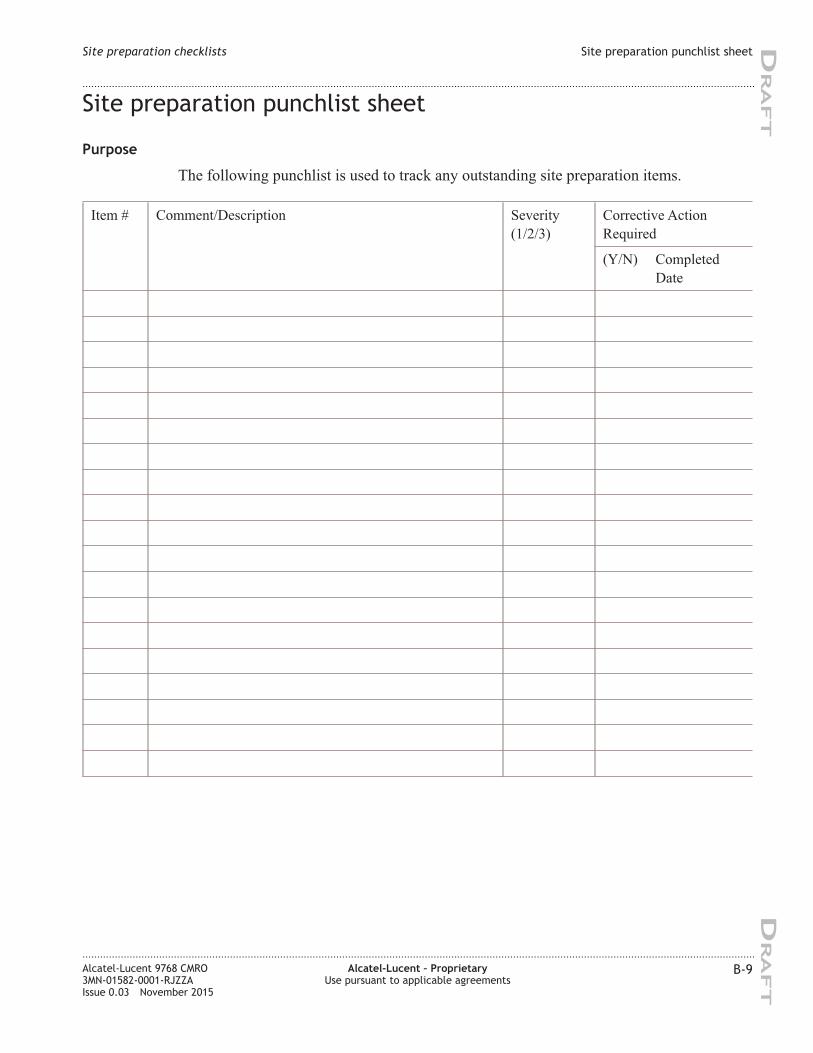
Site preparation punchlist sheet
Purpose
The following punchlist is used to track any outstanding site preparation items.
Item # Comment/Description Severity
(1/2/3)
Corrective Action
Required
(Y/N) Completed
Date
Site preparation checklists Site preparation punchlist sheet
....................................................................................................................................................................................................................................
....................................................................................................................................................................................................................................
Alcatel-Lucent 9768 CMRO
3MN-01582-0001-RJZZA
Issue 0.03 November 2015
Alcatel-Lucent – Proprietary
Use pursuant to applicable agreements
B-9
DRA
FT
DRA
FT
Site preparation checklists Site preparation punchlist sheet
....................................................................................................................................................................................................................................
....................................................................................................................................................................................................................................
B-10 Alcatel-Lucent – Proprietary
Use pursuant to applicable agreements
Alcatel-Lucent 9768 CMRO
3MN-01582-0001-RJZZA
Issue 0.03 November 2015
DRA
FT
DRA
FT
Appendix C: Product
conformance statements
Overview
Purpose
This section presents the product conformance statements that apply to the Alcatel-Lucent
9768 Metro Radio Outdoor product.
The statements that are required are determined primarily by national or multi-national
regulations. However, in some regions, contract terms determine which statements are
required.
The presence of the statement indicates that the product does comply with that statement
wherever it is required to do so.
Contents
United States compliance C-2
Federal Communications Commission C-2
Product safety conformance statements C-4
Antenna exposure statements C-5
FDA/IEC optical transmitter product compliance statements C-5
Eco-environmental statements C-6
Canadian compliance C-8
Industry Canada C-8
Product safety and exposure C-8
Antenna exposure statements C-9
IEC optical transmitter product compliance statements C-10
Eco-environmental statements C-11
...................................................................................................................................................................................................................................
Alcatel-Lucent 9768 CMRO
3MN-01582-0001-RJZZA
Issue 0.03 November 2015
Alcatel-Lucent – Proprietary
Use pursuant to applicable agreements
C-1
DRA
FT
DRA
FT
United States compliance
Introduction
Purpose
The statements that follow are the product conformance statements that apply to the
Alcatel-Lucent 9768 Metro Radio Outdoor Product when deployed in the United States.
Contents
Federal Communications Commission C-2
Product safety conformance statements C-4
Antenna exposure statements C-5
FDA/IEC optical transmitter product compliance statements C-5
Eco-environmental statements C-6
Federal Communications Commission
Federal Communications Commission
Important! Changes or modifications not expressly approved by Alcatel-Lucent, Inc.
could void the user’s authority to operate the equipment.
This device complies with Part 15 of the FCC Rules. Operation is subject to the following
two conditions:
(1) this device may not cause harmful interference, and
(2) this device must accept any interference received, including interference that may
cause undesired operation.
FCC Part 15 Class B
Note: This equipment has been tested and found to comply with the limits for a Class
B digital device, pursuant to Part 15 of the FCC Rules.
These limits are designed to provide reasonable protection against harmful
interference in a residential installation.
Product conformance statements
United States compliance
Introduction
....................................................................................................................................................................................................................................
....................................................................................................................................................................................................................................
C-2 Alcatel-Lucent – Proprietary
Use pursuant to applicable agreements
Alcatel-Lucent 9768 CMRO
3MN-01582-0001-RJZZA
Issue 0.03 November 2015
DRA
FT
DRA
FT
This equipment generates, uses, and can radiate radio frequency energy and, if not
installed and used in accordance with the instructions, may cause harmful interference
to radio communications. However, there is no guarantee that interference will not
occur in a particular installation.
If this equipment does cause harmful interference to radio or television reception,
which can be determined by turning the equipment off and on, the user is encouraged
to try to correct the interference by one or more of the following measures:
• Reorient or relocate the receiving antenna
• Increase the separation between the equipment and receiver
• Connect the equipment into an outlet on a circuit different from that to which the
receiver is connected
• Consult the dealer or an experienced radio/TV technician for help.
FCC Part 68
This equipment complies with Part 68 of the FCC rules and the requirements adopted by
the ACTA. At the upper-right-hand corner inside the cabinet assembly of this equipment
is a label that contains, among other information, a product identifier in the format of
AAAEQ##TXXXX. If requested, this number must be provided to the telephone
company.
FIC 04DU9-1SN.
SOC 6.0N
The T1 network interface on this equipment is hardwired to a punchdown block, which
meets the FCC specifications.
If this equipment causes harm to the telephone network, the telephone company will
notify you in advance that temporary discontinuance of service may be required.
However, if advance notice is not practical, the telephone company will notify the
customer as soon as possible. Also, you will be advised of your right to file a complaint
with the FCC if you believe it is necessary.
The telephone company may make changes in its facilities, equipment, operations, or
procedures that could affect the operation of the equipment. If this happens, the telephone
company will provide advance notice in order for you to make necessary modifications to
maintain uninterrupted service.
FCC regulations prohibit the connection of customer-provided equipment to central office
implemented systems. Connection to party lines is subject to tariffs; users should contact
their state public utility commission, public service commission, or corporation
commission for information.
Product conformance statements
United States compliance
Federal Communications Commission
....................................................................................................................................................................................................................................
....................................................................................................................................................................................................................................
Alcatel-Lucent 9768 CMRO
3MN-01582-0001-RJZZA
Issue 0.03 November 2015
Alcatel-Lucent – Proprietary
Use pursuant to applicable agreements
C-3
DRA
FT
DRA
FT
If the equipment is causing harm to the telephone network, the telephone company may
request that you disconnect the equipment until the problem is resolved.
If trouble is experienced with this equipment repair or warranty information may be
obtained by contacting:
Technical Support Services, within the United States: +1 630 224 4762, prompt 2
Product safety conformance statements
Product safety conformance
The Alcatel-Lucent 9768 Metro Radio Outdoor is Safety Certified ITE by CSA
International.
This Certification is marked on the equipment main nameplate label. Should the local
Authority Having Jurisdiction (AHJ) require prior or additional verification of this
Certification, a Product Certificate of Compliance can be obtained from the specific
Certification Body by the Business/Product Unit Applicant for the product or by
contacting:
Technical Support Services, within the United States: +1 630 224 4762, prompt 2
Any modifications to this equipment are not permitted without review and official written
authorization from the specific Certification Body. Unauthorized changes may violate the
Product Safety Certification. Modifications or changes authorized by official CN/CNN
are assumed to have received prior approval from this Lab.
Indoor applications
This equipment is intended for installation in restricted access locations where access is
controlled or where access can only be gained by service personnel with a key or tool.
Access to this equipment is restricted to qualified service personnel only.
Product conformance statements
United States compliance
Federal Communications Commission
....................................................................................................................................................................................................................................
....................................................................................................................................................................................................................................
C-4 Alcatel-Lucent – Proprietary
Use pursuant to applicable agreements
Alcatel-Lucent 9768 CMRO
3MN-01582-0001-RJZZA
Issue 0.03 November 2015
DRA
FT
DRA
FT
Antenna exposure statements
Antenna exposure
Antenna installations for the Alcatel-Lucent 9768 Metro Radio Outdoor product will be
performed in accordance with all applicable manufacturer's recommendations, and
national laws and regulations. To ensure correct antenna installation, the antenna installer
will perform all necessary calculations and/or field measurements to evaluate compliance
with applicable national laws or regulations regarding exposure to electromagnetic fields.
The supplier of radio equipment, the supplier of antenna equipment and the integrator and
builder of the site must provide sufficient information so that the limits of the exclusion
zones can be determined. Any changes to the antenna or other equipment in the transmit
path may require re-evaluation of the exposures to electromagnetic fields.
Pursuant to 47 CFR Part 1, Subpart I, subject to the provisions of section 1.1307, all
installations must be evaluated for requirements contained in Table 1, “Limits for
maximum permissible exposure,” in section 1.1310.
FDA/IEC optical transmitter product compliance statements
FDA/IEC optical transmitter product compliance
Alcatel-Lucent declares that this equipment complies with the Food and Drug
Administration’s Center for Devices and Radiological Health (FDA/CDRH) regulations
21 CFR 1040.10 and 1040.11. It is a Class I/1 laser optical fiber communication systems
“product” under the FDA.
This Product is designed to ensure that personnel operating the product are not
endangered by laser radiation during normal operation and fault conditions. This product
does not present a risk of eye injury because it is fully enclosed and does not contain
embedded lasers greater than Class I/1 unless otherwise noted.
Product conformance statements
United States compliance
Antenna exposure statements
....................................................................................................................................................................................................................................
....................................................................................................................................................................................................................................
Alcatel-Lucent 9768 CMRO
3MN-01582-0001-RJZZA
Issue 0.03 November 2015
Alcatel-Lucent – Proprietary
Use pursuant to applicable agreements
C-5
DRA
FT
DRA
FT
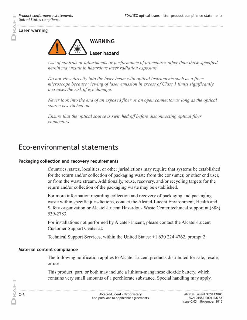
Laser warning
Eco-environmental statements
Packaging collection and recovery requirements
Countries, states, localities, or other jurisdictions may require that systems be established
for the return and/or collection of packaging waste from the consumer, or other end user,
or from the waste stream. Additionally, reuse, recovery, and/or recycling targets for the
return and/or collection of the packaging waste may be established.
For more information regarding collection and recovery of packaging and packaging
waste within specific jurisdictions, contact the Alcatel-Lucent Environment, Health and
Safety organization or Alcatel-Lucent Hazardous Waste Center technical support at (888)
539-2783.
For installations not performed by Alcatel-Lucent, please contact the Alcatel-Lucent
Customer Support Center at:
Technical Support Services, within the United States: +1 630 224 4762, prompt 2
Material content compliance
The following notification applies to Alcatel-Lucent products distributed for sale, resale,
or use.
This product, part, or both may include a lithium-manganese dioxide battery, which
contains very small amounts of a perchlorate substance. Special handling may apply.
WARNING
Use of controls or adjustments or performance of procedures other than those specifiedherein may result in hazardous laser radiation exposure.
Do not view directly into the laser beam with optical instruments such as a fibermicroscope because viewing of laser emission in excess of Class 1 limits significantlyincreases the risk of eye damage.
Never look into the end of an exposed fiber or an open connector as long as the opticalsource is switched on.
Ensure that the optical source is switched off before disconnecting optical fiberconnectors.
Laser hazard
Product conformance statements
United States compliance
FDA/IEC optical transmitter product compliance statements
....................................................................................................................................................................................................................................
....................................................................................................................................................................................................................................
C-6 Alcatel-Lucent – Proprietary
Use pursuant to applicable agreements
Alcatel-Lucent 9768 CMRO
3MN-01582-0001-RJZZA
Issue 0.03 November 2015
DRA
FT
DRA
FT
For California:
Perchlorate Material - special handling may apply.
See http://www.dtsc.ca.gov/hazardouswaste/perchlorate/.
Product conformance statements
United States compliance
Eco-environmental statements
....................................................................................................................................................................................................................................
....................................................................................................................................................................................................................................
Alcatel-Lucent 9768 CMRO
3MN-01582-0001-RJZZA
Issue 0.03 November 2015
Alcatel-Lucent – Proprietary
Use pursuant to applicable agreements
C-7
DRA
FT
DRA
FT
Canadian compliance
Introduction
Purpose
The statements that follow are the product conformance statement that apply to the
Alcatel-Lucent 9768 Compact Metro Radio Outdoor when deployed in Canada.
Contents
Industry Canada C-8
Product safety and exposure C-8
Antenna exposure statements C-9
IEC optical transmitter product compliance statements C-10
Eco-environmental statements C-11
Industry Canada
EMC approval
ICES-003: Interference-Causing Equipment Standard Digital Apparatus
The Alcatel-Lucent Metro Radio product complies with Canadian ICES-003.
Cet appareil numérique de la classe A est conforme à la norme NMB-003 du Canada.
Product safety and exposure
Product safety conformance
This equipment is safety certified to C22.2 No. 60950-1 for Canada by a laboratory
accredited by the Standards Council of Canada (SCC), such as CSA, UL, or others. The
product bears this certification mark of this certification laboratory on its main nameplate
label. Should the local authority having jurisdiction (AHJ) require prior or additional
verification of this certification, a product certificate of compliance can be obtained from
the specific certification laboratory by the business/product unit Applicant for the product.
Any modifications to this equipment are not permitted without review and written official
Product conformance statements
Canadian compliance
Overview
....................................................................................................................................................................................................................................
....................................................................................................................................................................................................................................
C-8 Alcatel-Lucent – Proprietary
Use pursuant to applicable agreements
Alcatel-Lucent 9768 CMRO
3MN-01582-0001-RJZZA
Issue 0.03 November 2015
DRA
FT
DRA
FT
authorization from the specific certification laboratory. Unauthorized changes may violate
the product safety certification. Modifications or changes authorized by official CN/CNN
are assumed to have received prior approval from this Lab.
Human exposure
Pursuant to Health Canada Safety Code 6, Limits of Human Exposure to Radio frequency
Electromagnetic Fields in the Frequency Range from 3 kHz to 300 GHz, all installations
must be evaluated against the Maximum Exposure Limits as described in Health Canada
99-EHD-237.
Antenna exposure statements
Antenna exposure
Antenna installations for this equipment shall be performed in accordance with all
applicable manufacturer's recommendations, and national laws and regulations. To ensure
correct antenna installation, the antenna installer shall perform all necessary calculations
and/or field measurements to evaluate compliance with applicable national laws or
regulations regarding exposure to electromagnetic fields.
The supplier of radio equipment, the supplier of antenna equipment and the integrator and
builder of the site must provide sufficient information so that the limits of the exclusion
zones can be determined. Any changes to the antenna or other equipment in the transmit
path may require re-evaluation of the exposures to electromagnetic fields.
The antenna(s) used for this transmitter must be installed to provide a separation distance
of at least 1.8 m from all persons.
Les antennes utilisées pour cet émetteur doivent être installées de façon à respecter une
distance de sécurité d'au moins 1.8 m.
Product conformance statements
Canadian compliance
Product safety and exposure
....................................................................................................................................................................................................................................
....................................................................................................................................................................................................................................
Alcatel-Lucent 9768 CMRO
3MN-01582-0001-RJZZA
Issue 0.03 November 2015
Alcatel-Lucent – Proprietary
Use pursuant to applicable agreements
C-9
DRA
FT
DRA
FT
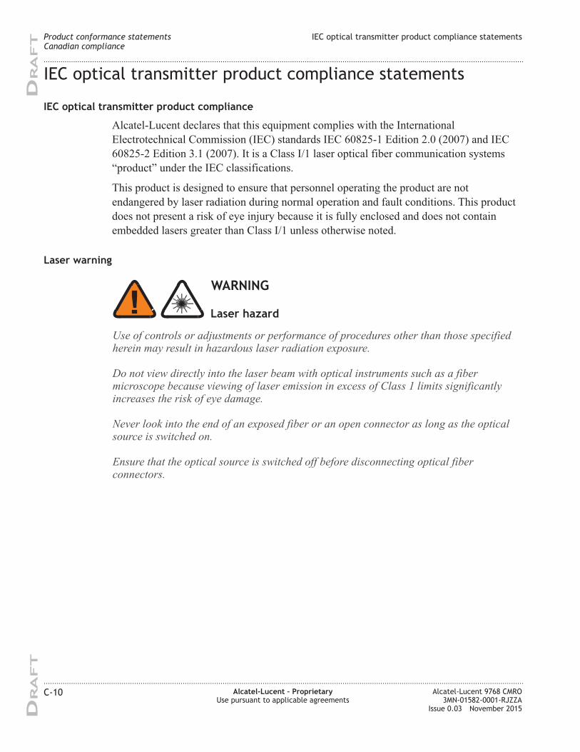
IEC optical transmitter product compliance statements
IEC optical transmitter product compliance
Alcatel-Lucent declares that this equipment complies with the International
Electrotechnical Commission (IEC) standards IEC 60825-1 Edition 2.0 (2007) and IEC
60825-2 Edition 3.1 (2007). It is a Class I/1 laser optical fiber communication systems
“product” under the IEC classifications.
This product is designed to ensure that personnel operating the product are not
endangered by laser radiation during normal operation and fault conditions. This product
does not present a risk of eye injury because it is fully enclosed and does not contain
embedded lasers greater than Class I/1 unless otherwise noted.
Laser warning
WARNING
Use of controls or adjustments or performance of procedures other than those specifiedherein may result in hazardous laser radiation exposure.
Do not view directly into the laser beam with optical instruments such as a fibermicroscope because viewing of laser emission in excess of Class 1 limits significantlyincreases the risk of eye damage.
Never look into the end of an exposed fiber or an open connector as long as the opticalsource is switched on.
Ensure that the optical source is switched off before disconnecting optical fiberconnectors.
Laser hazard
Product conformance statements
Canadian compliance
IEC optical transmitter product compliance statements
....................................................................................................................................................................................................................................
....................................................................................................................................................................................................................................
C-10 Alcatel-Lucent – Proprietary
Use pursuant to applicable agreements
Alcatel-Lucent 9768 CMRO
3MN-01582-0001-RJZZA
Issue 0.03 November 2015
DRA
FT
DRA
FT
Eco-environmental statements
Packaging collection and recovery requirements
Countries, states, localities, or other jurisdictions may require that systems be established
for the return and/or collection of packaging waste from the consumer, or other end user,
or from the waste stream. Additionally, reuse, recovery, and/or recycling targets for the
return and/or collection of the packaging waste may be established.
For more information regarding collection and recovery of packaging and packaging
waste within specific jurisdictions, contact the Alcatel-Lucent Environment, Health and
Safety organization or Alcatel-Lucent Hazardous Waste Center technical support at (888)
539-2783.
For installations not performed by Alcatel-Lucent, please contact the Alcatel-Lucent
Customer Support Center at:
Technical Support Services, within Canada: +1 630 224 4672, prompt 2
Product conformance statements
Canadian compliance
Eco-environmental statements
....................................................................................................................................................................................................................................
....................................................................................................................................................................................................................................
Alcatel-Lucent 9768 CMRO
3MN-01582-0001-RJZZA
Issue 0.03 November 2015
Alcatel-Lucent – Proprietary
Use pursuant to applicable agreements
C-11
DRA
FT
DRA
FT
Product conformance statements Eco-environmental statements
....................................................................................................................................................................................................................................
....................................................................................................................................................................................................................................
C-12 Alcatel-Lucent – Proprietary
Use pursuant to applicable agreements
Alcatel-Lucent 9768 CMRO
3MN-01582-0001-RJZZA
Issue 0.03 November 2015
DRA
FT
DRA
FT
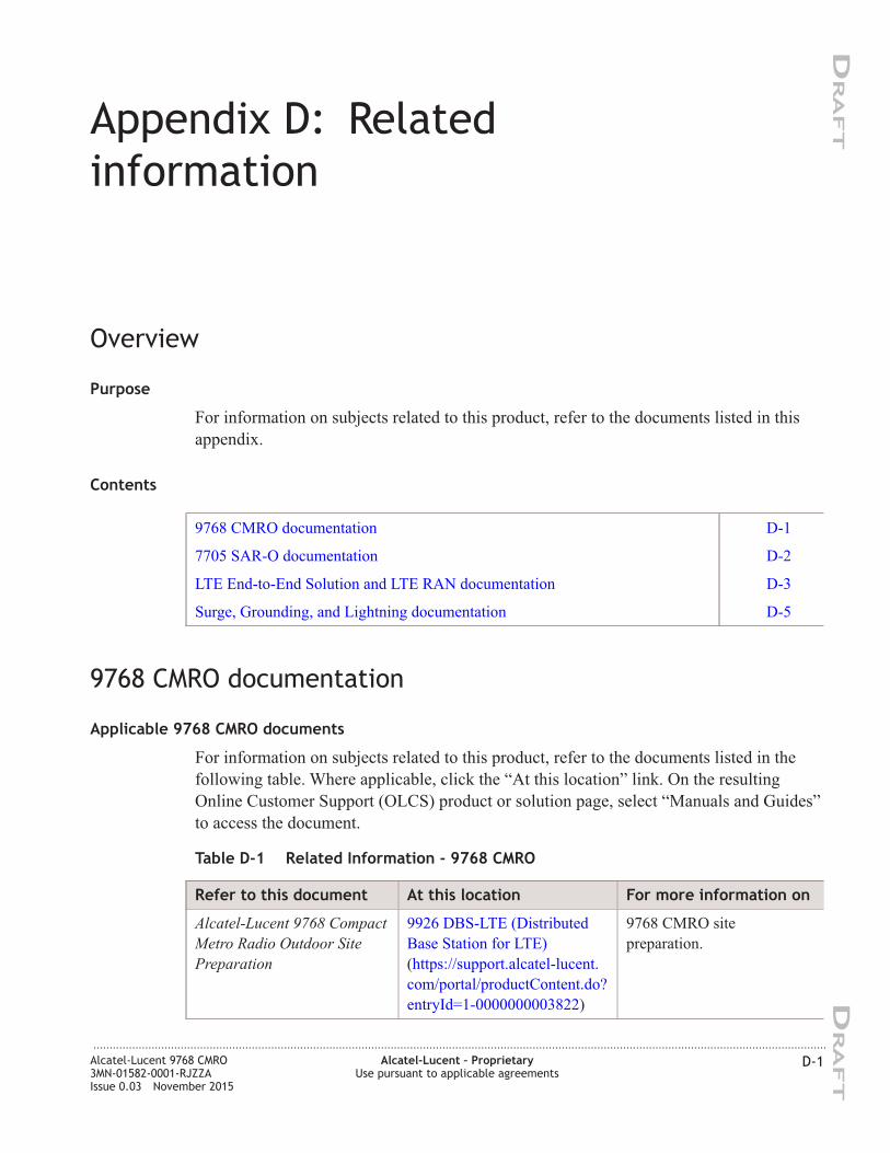
Appendix D: Related
information
Overview
Purpose
For information on subjects related to this product, refer to the documents listed in this
appendix.
Contents
9768 CMRO documentation D-1
7705 SAR-O documentation D-2
LTE End-to-End Solution and LTE RAN documentation D-3
Surge, Grounding, and Lightning documentation D-5
9768 CMRO documentation
Applicable 9768 CMRO documents
For information on subjects related to this product, refer to the documents listed in the
following table. Where applicable, click the “At this location” link. On the resulting
Online Customer Support (OLCS) product or solution page, select “Manuals and Guides”
to access the document.
Table D-1 Related Information - 9768 CMRO
Refer to this document At this location For more information on
Alcatel-Lucent 9768 Compact
Metro Radio Outdoor Site
Preparation
9926 DBS-LTE (Distributed
Base Station for LTE)
(https://support.alcatel-lucent.
com/portal/productContent.do?
entryId=1-0000000003822)
9768 CMRO site
preparation.
...................................................................................................................................................................................................................................
Alcatel-Lucent 9768 CMRO
3MN-01582-0001-RJZZA
Issue 0.03 November 2015
Alcatel-Lucent – Proprietary
Use pursuant to applicable agreements
D-1
DRA
FT
DRA
FT
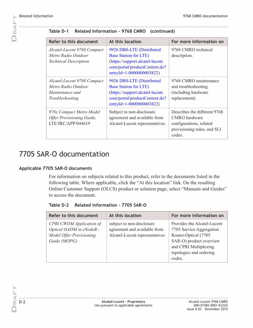
Table D-1 Related Information - 9768 CMRO (continued)
Refer to this document At this location For more information on
Alcatel-Lucent 9768 Compact
Metro Radio Outdoor
Technical Description
9926 DBS-LTE (Distributed
Base Station for LTE)
(https://support.alcatel-lucent.
com/portal/productContent.do?
entryId=1-0000000003822)
9768 CMRO technical
description.
Alcatel-Lucent 9768 Compact
Metro Radio Outdoor
Maintenance and
Troubleshooting
9926 DBS-LTE (Distributed
Base Station for LTE)
(https://support.alcatel-lucent.
com/portal/productContent.do?
entryId=1-0000000003822)
9768 CMRO maintenance
and troubleshooting
(including hardware
replacement).
976x Compact Metro Model
Offer Provisioning Guide,
LTE/IRC/APP/044619
Subject to non-disclosure
agreement and available from
Alcatel-Lucent representatives.
Describes the different 9768
CMRO hardware
configurations, related
provisioning rules, and SLI
codes.
7705 SAR-O documentation
Applicable 7705 SAR-O documents
For information on subjects related to this product, refer to the documents listed in the
following table. Where applicable, click the “At this location” link. On the resulting
Online Customer Support (OLCS) product or solution page, select “Manuals and Guides”
to access the document.
Table D-2 Related information - 7705 SAR-O
Refer to this document At this location For more information on
CPRI CWDM Application of
Optical OADM in eNodeB -
Model Offer Provisioning
Guide (MOPG)
subject to non-disclosure
agreement and available from
Alcatel-Lucent representatives
Provides the Alcatel-Lucent
7705 Service Aggregation
Router-Optical (7705
SAR-O) product overview
and CPRI Multiplexing
topologies and ordering
codes.
Related information 9768 CMRO documentation
....................................................................................................................................................................................................................................
....................................................................................................................................................................................................................................
D-2 Alcatel-Lucent – Proprietary
Use pursuant to applicable agreements
Alcatel-Lucent 9768 CMRO
3MN-01582-0001-RJZZA
Issue 0.03 November 2015
DRA
FT
DRA
FT
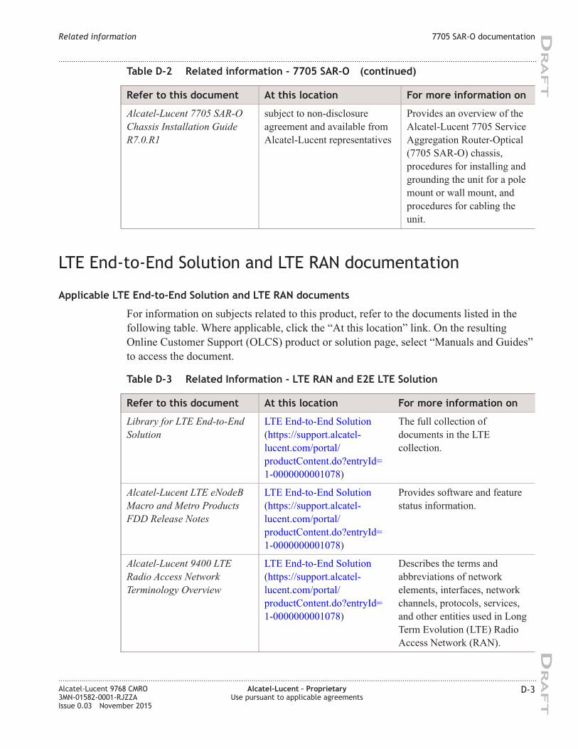
Table D-2 Related information - 7705 SAR-O (continued)
Refer to this document At this location For more information on
Alcatel-Lucent 7705 SAR-O
Chassis Installation Guide
R7.0.R1
subject to non-disclosure
agreement and available from
Alcatel-Lucent representatives
Provides an overview of the
Alcatel-Lucent 7705 Service
Aggregation Router-Optical
(7705 SAR-O) chassis,
procedures for installing and
grounding the unit for a pole
mount or wall mount, and
procedures for cabling the
unit.
LTE End-to-End Solution and LTE RAN documentation
Applicable LTE End-to-End Solution and LTE RAN documents
For information on subjects related to this product, refer to the documents listed in the
following table. Where applicable, click the “At this location” link. On the resulting
Online Customer Support (OLCS) product or solution page, select “Manuals and Guides”
to access the document.
Table D-3 Related Information - LTE RAN and E2E LTE Solution
Refer to this document At this location For more information on
Library for LTE End-to-End
Solution
LTE End-to-End Solution
(https://support.alcatel-
lucent.com/portal/
productContent.do?entryId=
1-0000000001078)
The full collection of
documents in the LTE
collection.
Alcatel-Lucent LTE eNodeB
Macro and Metro Products
FDD Release Notes
LTE End-to-End Solution
(https://support.alcatel-
lucent.com/portal/
productContent.do?entryId=
1-0000000001078)
Provides software and feature
status information.
Alcatel-Lucent 9400 LTE
Radio Access Network
Terminology Overview
LTE End-to-End Solution
(https://support.alcatel-
lucent.com/portal/
productContent.do?entryId=
1-0000000001078)
Describes the terms and
abbreviations of network
elements, interfaces, network
channels, protocols, services,
and other entities used in Long
Term Evolution (LTE) Radio
Access Network (RAN).
Related information 7705 SAR-O documentation
....................................................................................................................................................................................................................................
....................................................................................................................................................................................................................................
Alcatel-Lucent 9768 CMRO
3MN-01582-0001-RJZZA
Issue 0.03 November 2015
Alcatel-Lucent – Proprietary
Use pursuant to applicable agreements
D-3
DRA
FT
DRA
FT
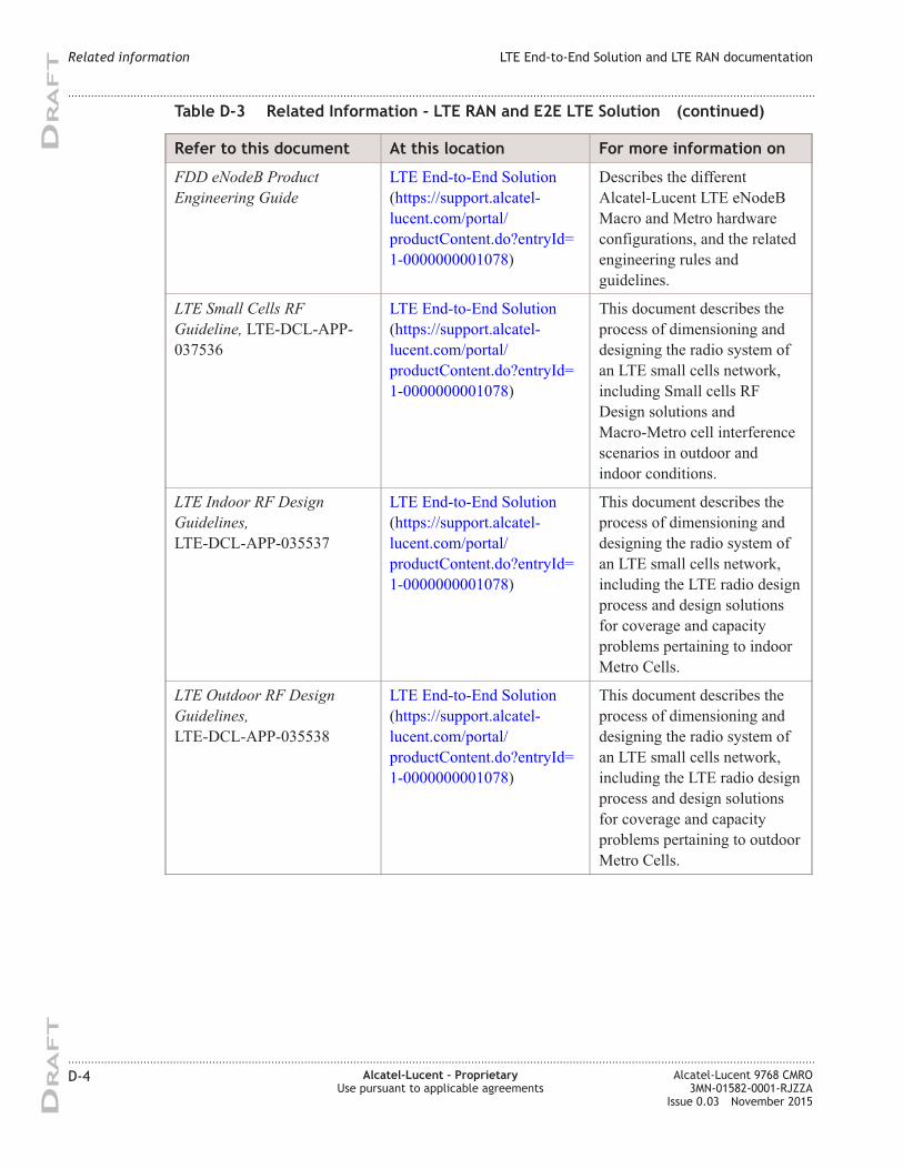
Table D-3 Related Information - LTE RAN and E2E LTE Solution (continued)
Refer to this document At this location For more information on
FDD eNodeB Product
Engineering Guide
LTE End-to-End Solution
(https://support.alcatel-
lucent.com/portal/
productContent.do?entryId=
1-0000000001078)
Describes the different
Alcatel-Lucent LTE eNodeB
Macro and Metro hardware
configurations, and the related
engineering rules and
guidelines.
LTE Small Cells RF
Guideline, LTE-DCL-APP-
037536
LTE End-to-End Solution
(https://support.alcatel-
lucent.com/portal/
productContent.do?entryId=
1-0000000001078)
This document describes the
process of dimensioning and
designing the radio system of
an LTE small cells network,
including Small cells RF
Design solutions and
Macro-Metro cell interference
scenarios in outdoor and
indoor conditions.
LTE Indoor RF Design
Guidelines,
LTE-DCL-APP-035537
LTE End-to-End Solution
(https://support.alcatel-
lucent.com/portal/
productContent.do?entryId=
1-0000000001078)
This document describes the
process of dimensioning and
designing the radio system of
an LTE small cells network,
including the LTE radio design
process and design solutions
for coverage and capacity
problems pertaining to indoor
Metro Cells.
LTE Outdoor RF Design
Guidelines,
LTE-DCL-APP-035538
LTE End-to-End Solution
(https://support.alcatel-
lucent.com/portal/
productContent.do?entryId=
1-0000000001078)
This document describes the
process of dimensioning and
designing the radio system of
an LTE small cells network,
including the LTE radio design
process and design solutions
for coverage and capacity
problems pertaining to outdoor
Metro Cells.
Related information LTE End-to-End Solution and LTE RAN documentation
....................................................................................................................................................................................................................................
....................................................................................................................................................................................................................................
D-4 Alcatel-Lucent – Proprietary
Use pursuant to applicable agreements
Alcatel-Lucent 9768 CMRO
3MN-01582-0001-RJZZA
Issue 0.03 November 2015
DRA
FT
DRA
FT
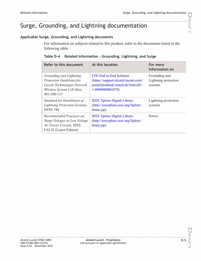
Surge, Grounding, and Lightning documentation
Applicable Surge, Grounding, and Lightning documents
For information on subjects related to this product, refer to the documents listed in the
following table.
Table D-4 Related Information - Grounding, Lightning, and Surge
Refer to this document At this location For more
information on
Grounding and Lightning
Protection Guidelines for
Lucent Technologies Network
Wireless System Cell Sites,
401-200-115
LTE End-to-End Solution
(https://support.alcatel-lucent.com/
portal/productContent.do?entryId=
1-0000000001078)
Grounding and
Lightning protection
systems
Standard for Installation of
Lightning Protection Systems,
NFPA 780
IEEE Xplore Digital Library
(http://ieeexplore.ieee.org/Xplore/
home.jsp)
Lightning protection
systems
Recommended Practices on
Surge Voltages in Low Voltage
AC Power Circuits, IEEE
C62.41 (Latest Edition)
IEEE Xplore Digital Library
(http://ieeexplore.ieee.org/Xplore/
home.jsp)
Power
Related information Surge, Grounding, and Lightning documentation
....................................................................................................................................................................................................................................
....................................................................................................................................................................................................................................
Alcatel-Lucent 9768 CMRO
3MN-01582-0001-RJZZA
Issue 0.03 November 2015
Alcatel-Lucent – Proprietary
Use pursuant to applicable agreements
D-5
DRA
FT
DRA
FT
Related information Surge, Grounding, and Lightning documentation
....................................................................................................................................................................................................................................
....................................................................................................................................................................................................................................
D-6 Alcatel-Lucent – Proprietary
Use pursuant to applicable agreements
Alcatel-Lucent 9768 CMRO
3MN-01582-0001-RJZZA
Issue 0.03 November 2015
DRA
FT
DRA
FT
Glossary
This glossary provides a quick reference to the terms, acronyms, and abbreviations commonly
used in the Alcatel-Lucent Metro product documentation.
...................................................................................................................................................................................................................................
Numerics
3G
Third Generation
3GPP
3rd Generation Partnership Project
A collaboration between groups of telecommunications associations for the promotion and
standardization of high-speed cellular services.
5620 SAM
5620 Service Aware Manager
9952 WPS
9952 Wireless Provisioning System
...................................................................................................................................................................................................................................
A A (Ampere)
Base SI unit of electrical current.
SI is the International System of Units (abbreviated SI from French: Le Système international
d'units).
A-GPS
Assisted Global Positioning System
AAA
Authentication, Authorization, and Accounting
AC
Access Class
AC (Alternating Current)
Continuously variable current, rising to a maximum in one direction, falling to zero, then
reversing direction and repeating the cycle in the other direction.
....................................................................................................................................................................................................................................
Alcatel-Lucent 9768 CMRO
3MN-01582-0001-RJZZA
Issue 0.03 November 2015
Alcatel-Lucent – Proprietary
Use pursuant to applicable agreements
GL-1
DRA
FT
DRA
FT
AC convenience outlet
Sites must be equipped with at least two duplex outlets for installation and maintenance
procedures. The outlets are required to power test equipment and installation tools.
ACF (AC Fail)
The AC Fail (ACF) alarm indicates that AC input to one or more rectifiers in the power plant is
absent or outside of the operating range of the equipment
ACLR
Adjacent Channel Leakage power Ratio
AHJ
The agency or authority having jurisdiction. Article 100 of the National Electrical Code (NEC) for
the United States defines AHJ with greater specificity, stating that it may be a federal, state, local
government, or individual such as a fire chief, fire marshal, chief of a fire prevention bureau,
labor department or health department, building official or electrical inspector, or others having
statutory authority. In some circumstances, the property owner or his/her agent assumes the roles,
and at government installations, the commanding officer or departmental official may be the AHJ.
Ambient temperature
The temperature of air or other media in a designated area, particularly the area
ANR
Automatic Neighbor Relation
ANSI (American National Standards Institute)
An organization chartered to accredit standards developed by a wide variety of industry groups,
without influence from any one company or organization. Does not develop standards, but
reviews and implements standards developed by other organizations. ANSI is a member of the
International Standards Organization (ISO).
Antenna
An elevated device for radiating or receiving radio waves. It changes electrical currents into
electromagnetic waves, and conversely, electromagnetic waves into electrical currents.
AP
Access Point
AP (Application Processor)
Network element located at the MSC which provides the radio control logic for managing calls.
The AP is a general-purpose computer that can host a number of RCS virtual machines.
AWG (American Wire Gauge)
American standard for classifying wire diameter.
...................................................................................................................................................................................................................................
B backhaul
The portion of the network connecting the base band unit (BBU) to the mobile core network.
Glossary
....................................................................................................................................................................................................................................
....................................................................................................................................................................................................................................
GL-2 Alcatel-Lucent – Proprietary
Use pursuant to applicable agreements
Alcatel-Lucent 9768 CMRO
3MN-01582-0001-RJZZA
Issue 0.03 November 2015
DRA
FT
DRA
FT
Backup
Facility used to replace an element which has failed.
Base station
The equipment that provides the air interface that allows mobile terminals to communicate with
the telecommunications network.
BBU
BaseBand Unit
BD (Battery on Discharge, first stage)
The Batteries on Discharge (BD) alarm indicates the power system output voltage has decreased
below the “batteries on discharge” threshold set point. The “batteries on discharge” threshold is
set for 50.0 volts (for -48-VDC systems) or 25.0 volts (for +24-VDC systems).
BD-2 (Battery on Discharge-2)
The Batteries on Discharge (BD-2) alarm indicates the power system output voltage has decreased
below the “batteries on a second discharge” threshold set point. The “batteries on a second
discharge” threshold is set for 44.0 volts (for -48-VDC systems) or 22.0 volts (for +24-VDC
systems).
BOCA
Building Officials and Code Administrators
Bonding
Permanent connection of metallic parts to form an electrically conductive path that assures
electrical continuity and has the capability to safely conduct any current likely to be imposed.
Branch circuit
The circuit conductors between the final overcurrent device protecting the circuit and the outlet.
Breaker, circuit
A cut-out device which breaks a circuit when preset limits of current are exceeded.
Buried cable
A communication cable manufactured or produced for the purpose of burial in direct contact with
the earth.
Buried ring ground
A buried, bare, tinned, solid copper cable encircling the site building and/or tower foundation.
Bus bar
One or more conductors that serves as a common connection for a group of related devices.
Busy hour
The uninterrupted period of 60 minutes for which the average intensity of traffic is at maximum.
Glossary
....................................................................................................................................................................................................................................
....................................................................................................................................................................................................................................
Alcatel-Lucent 9768 CMRO
3MN-01582-0001-RJZZA
Issue 0.03 November 2015
Alcatel-Lucent – Proprietary
Use pursuant to applicable agreements
GL-3
DRA
FT
DRA
FT
BW
Bandwidth
...................................................................................................................................................................................................................................
C Cable run
Referring to cable routing.
Cable sweep
(See Sweep)
CAN/CSA
Canadian Standards Association. See http://www.csa.ca (http://www.csa.ca).
CDRH
Center for Devices and Radiological Health
CE
Conformité Européene
A CE Marking on a product is a manufacturer's declaration that the product complies with the
essential requirements of the relevant European health, safety and environmental protection
legislation.
Cell site
An installation located within a cell that houses the equipment needed to set up and complete calls
on a cellular telephone.
CFR
Code of Federal Regulations.
Among these regulations, Title 47, “Telecommunication,” conveys the rules of the FCC
companies operating networks in the USA. See also FCC.
CIC (Customer Information Center)
Source for locating and obtaining delivery of Alcatel-Lucent customer documents.
Circuit
1. The complete path between two terminals over which one-way or two-way communications
may be provided. 2. An electronic path between two or more points, capable of providing a
number of channels. 3. A number of conductors connected together for the purpose of carrying an
electrical current. 4. An electronic closed-loop path among two or more points used for signal
transfer. 5. A number of electrical components, such as resistors, inductances, capacitors,
transistors, and power sources connected together in one or more closed loops.
CISPR
The [special] international committee on radio interference. Its publication CISPR 22, Information
Technology Equipment—Radio Disturbance Characteristics—Limits and Methods of
Measurement addresses any device that emits RF outside the scope of its intended purpose.
Glossary
....................................................................................................................................................................................................................................
....................................................................................................................................................................................................................................
GL-4 Alcatel-Lucent – Proprietary
Use pursuant to applicable agreements
Alcatel-Lucent 9768 CMRO
3MN-01582-0001-RJZZA
Issue 0.03 November 2015
DRA
FT
DRA
FT
CLI
Command Line Interface
CMAS
Commercial Mobile Alert System
CMS
Certificate Management System
CN/CNN
Arcane term for changes notices that affect Alcatel-Lucent products.
Coaxial cable
A cable with one or more coaxial pairs under one outer sheath. The cable consists of a center
conductor surrounded by an insulating material and a concentric outer conductor.
Configuration
An arrangement of functional units according to their nature, number, and chief characteristics.
Controlled environment
An indoor location in which temperature, humidity, and ventilation are maintained at specific
levels.
Core
A subset of generic requirements published by Telcordia Technologies. See also GR. The Core
requirements that affect the Metro product (Radio/Cell) concern spurious emissions, surges from
lightning, and resistance to wind, wind-driven rain, salt fog, and extreme ambient temperature.
CPC
Circular Plastic Connector
CPRI
Common Public Radio Interface
CS
Circuit Switched
CSA
Convergent Security Asset
CSA (Canadian Standards Association)
An independent, non-government, not-for-profit association for the development, by consensus,
of Canadian standards and product certifications.
CSC (Cell Site Configuration)
Sheets provided in this document for documenting cell site configuration, conditions, and other
pertinent information for reference during product deployment, and future additions.
Glossary
....................................................................................................................................................................................................................................
....................................................................................................................................................................................................................................
Alcatel-Lucent 9768 CMRO
3MN-01582-0001-RJZZA
Issue 0.03 November 2015
Alcatel-Lucent – Proprietary
Use pursuant to applicable agreements
GL-5
DRA
FT
DRA
FT
...................................................................................................................................................................................................................................
D d2U
digital 2U-height box.
The BBU system supporting two controller and two modems. See also BBU.
dB (decibel)
A unit which expresses the ratio of two voltages, currents, or powers. Decibel (dB) is used to
specify transmission loss, gain, or relative level. Decibel (dB) equal to 20 times the common
logarithm of the ratio of two voltages or two currents, or 10 times the common logarithm of the
ratio of two powers.
dBi (decibels (dB) relative to isotropic)
Decibels relative to an isotropic antenna gain at radio frequencies.
Antenna gain is usually defined as the ratio of the power produced by the antenna from a far-field
source on the antenna's beam axis to the power produced by a hypothetical lossless isotropic
antenna, which is equally sensitive to signals from all directions. Usually this ratio is expressed in
decibels, and these units are referred to as "decibels-isotropic" (dBi).
DC (Direct Current)
Current flow in one direction.
DFS
Dynamic Frequency Selection
DHCP
Dynamic Host Configuration Protocol
Diversity
A method of radio transmission and/or reception, which counteracts the effects of fading by
combining several signals all bearing the same information.
DL
Downlink
DNS
Domain Name System
DoS
Denial of Service
Down conductor
A vertical conductor of low impedance that connects the cell site grounding electrode system to
the grounding electrode system.
Driven ground rod
A copper-clad steel or stainless steel rod, a minimum of 2.4 meters (8 feet) long and 5/8 inch in
diameter.
Glossary
....................................................................................................................................................................................................................................
....................................................................................................................................................................................................................................
GL-6 Alcatel-Lucent – Proprietary
Use pursuant to applicable agreements
Alcatel-Lucent 9768 CMRO
3MN-01582-0001-RJZZA
Issue 0.03 November 2015
DRA
FT
DRA
FT
DRX
Discontinuous Reception
DSCP
Differentiated Services Code Point
...................................................................................................................................................................................................................................
E E1
A four-wire voice and data trunking facility that carries 30 duplex channels in 64-kbps time slices.
E1 facilities are commonly used in countries outside of North America.
Earthquake zone
Seismic ratings ranging from zone 1 (relatively low central office operational shock and vibration
levels) to the most severe zone 4 levels. Equipment must be able to withstand earthquake zone
requirements under both operational and non-operational conditions.
ECID
Enhanced Cell ID
EEC directive
A law enacted by the European Union for enforcement by its Common Market. The terms of such
a law have been used as a point of reference against which to compare the intentional RF
emissions of the MRO.
EIRP
Effective Isotropic Radiated Power
Electrolytic ground electrode (rods)
A low resistance grounding rod (pipe) using low resistivity materials.
EMS
Element Management System
ESD
Electrostatic discharge.
A hazard that electronic equipment such as the Metro Cell or Metro Radio can suffer by way of
exposure to static electricity or proximity to something that has no connection to ground.
ETSI
European Telecommunications Standards Institute
EU
European Union
Exothermic weld
A method of making electrical connections of copper to copper or copper to steel using high
temperature fusion. The molten copper flows over conductors in a mold, melting, and welding
them together.
Glossary
....................................................................................................................................................................................................................................
....................................................................................................................................................................................................................................
Alcatel-Lucent 9768 CMRO
3MN-01582-0001-RJZZA
Issue 0.03 November 2015
Alcatel-Lucent – Proprietary
Use pursuant to applicable agreements
GL-7
DRA
FT
DRA
FT
...................................................................................................................................................................................................................................
F FA (Fuse Alarm)
The fuse alarm (FA) indicates that the power system battery and load protection fuse opens.
Facility
Any element of physical telephone equipment needed to provide service, such as cables,
switching systems, and microwave radio transmission systems.
FCC (Federal Communications Commission)
A group founded in 1934 to regulate all types of communications in the United States.
FDA
Food and Drug Administration
FDD
Frequency Division Duplex
Float
To operate a power load on a main-driven rectifier in parallel with a low impedance storage
battery, which is kept fully charged by the rectifier and is itself only called upon to provide power
during temporary and short-duration peaks for which the rectifier output is insufficient.
FM
Fault Management
FQDN
Fully Qualified Domain Name
Frequency
For a periodic wave, such as alternating current, the number of complete cycles per unit of time.
The unit of frequency is cycles per second, or hertz.
fronthaul
The common public radio interface (CPRI) connection between a standalone remote radio head
(for example: 9768 MRO, 9768 CMRO) and the base band unit (BBU).
FRU
Field Replaceable Unit
Full AXS
Cable connector used for CPRI connection to the Metro product (Radio/Cell).
Fuse
An overcurrent protective device that has as its critical component a metal wire or strip that will
melt when heated by a prescribed (design) amperage, creating an open in the circuit of which it is
a part, thereby protecting the circuit from an overcurrent condition.
Glossary
....................................................................................................................................................................................................................................
....................................................................................................................................................................................................................................
GL-8 Alcatel-Lucent – Proprietary
Use pursuant to applicable agreements
Alcatel-Lucent 9768 CMRO
3MN-01582-0001-RJZZA
Issue 0.03 November 2015
DRA
FT
DRA
FT
...................................................................................................................................................................................................................................
G GA
General Availability
Gain
The ratio of output current, voltage, or power to input current, voltage, or power, respectively.
Gain is usually expressed in dB. If the ratio is less than unity, the gain, expressed in dB, will be
negative, in which case there is a loss between input and output.
Garmin 45XLS
A handheld GPS receiver that can be used to verify GPS reception at a cell site. It has a removable
antenna and provides +5 VDC on the center pin of the RF connection to power external active
antennas. If poor GPS reception is suspected, the Garmin 45XLS can be used to verify that the
GPS antenna and cable system is working acceptably. It will also verify that the GPS antenna
location is acceptable.
GE (Gig-E, GBE)
Gigabit Ethernet
GFCI (Ground Fault Circuit Interrupter)
A device intended for protection of personnel that functions to de-energize a circuit or portion
thereof within an established period of time when a current to ground exceeds some
predetermined value that is less than that required to operate the overcurrent protective device of
the supply circuit.
GHz
GigaHertz
GLONASS
GLONASS is an acronym, which stands for Globalnaya Navigazionnaya Sputnikovaya Sistema,
or Global Navigation Satellite System. GLONASS is a satellite navigation system operated by the
Russia.
GNSS
Global Navigation Satellite System
GPON
Gigabit Passive Optical Network
GPRS
General Packet Radio Services
GPS (Global Positioning System)
A system of 24 satellites that provides, among other things, extremely accurate timing information
to the cell sites.
GR
Generic requirements published by Telcordia Technologies. See also Core.
Glossary
....................................................................................................................................................................................................................................
....................................................................................................................................................................................................................................
Alcatel-Lucent 9768 CMRO
3MN-01582-0001-RJZZA
Issue 0.03 November 2015
Alcatel-Lucent – Proprietary
Use pursuant to applicable agreements
GL-9
DRA
FT
DRA
FT
Ground
A conducting connection between equipment or an electrical circuit and earth, or conductive body
that is used in place of earth
Grounding conductor
A conductor used to connect equipment or a grounded electrical circuit to the grounding electrode
system.
Grounding electrode system
The conductive objects that are intentionally bonded to furnish connection to earth (that is, buried
ring ground with ground rods, electrically continuous buried metallic water pipe, electrolytic
ground electrode, and so on).
GTP
GPRS Tunneling Protocol
GUI
Graphical User Interface
Guy
Steel wire or rope used to hold a pole upright.
...................................................................................................................................................................................................................................
H Handoff
A automatic transfer of a cellular telephone call from one cell to another, maintaining call quality
as the mobile user moves through the coverage area.
HDM
Home Device Manager
Heat dissipation
The heat generated by cabinets during operation.
HPBW
Half Power Beamwidth
HSDPA
High-Speed Downlink Packet Access
HSPA
High-Speed Packet Access
HSUPA
High-Speed Uplink Packet Access
HTTP
Hypertext Transfer Protocol
Glossary
....................................................................................................................................................................................................................................
....................................................................................................................................................................................................................................
GL-10 Alcatel-Lucent – Proprietary
Use pursuant to applicable agreements
Alcatel-Lucent 9768 CMRO
3MN-01582-0001-RJZZA
Issue 0.03 November 2015
DRA
FT
DRA
FT
HV
High Voltage
HVAC (Heating, Ventilation, Air Conditioning)
Hz (hertz)
A unit of frequency of a periodic process equal to one cycle per second.
...................................................................................................................................................................................................................................
I I2C
Inter-integrated Circuit
ICNIRP
International Commission for Non-Ionizing Radiation Protection
IEC
International Electrotechnical Commission. The Metro products comply with numerous standards
that this independent body has propagated.
IEEE
Institute of Electrical and Electronics Engineers
Indoor site
Installation site in a controlled environment, allowing the use of indoor cabinets.
INTR (Intrusion Alarm)
The Intrusion (INTR) alarm indicates a door or access panel to the power system is open.
IP
Internet Protocol
IPsec
Internet Protocol Security
IPx5
The subset of the standard IEC 60529 to which the Metro product (Radio/Cell) conforms in its
resistance to intrusion by water. Conformance to this subset means that the Metro product
(Radio/Cell) withstands a 3 minutes test of 12.5 liters/minute at 30 kN/m2 from 3 meters away.
IRC
Interference Rejection Combining
ISM
Industrial, Scientific, and Medical
IT
In an IT earthing system, the electrical distribution system has no connection to earth at all, or it
has only a high impedance connection. In such systems, an insulation monitoring device is used to
Glossary
....................................................................................................................................................................................................................................
....................................................................................................................................................................................................................................
Alcatel-Lucent 9768 CMRO
3MN-01582-0001-RJZZA
Issue 0.03 November 2015
Alcatel-Lucent – Proprietary
Use pursuant to applicable agreements
GL-11
DRA
FT
DRA
FT
monitor the impedance.
...................................................................................................................................................................................................................................
L LAN
Local Area Network
LC
A small connector that terminates a fiber optic cable and snaps into its mate.
LED
light emitting diode
LMT
Local Maintenance Terminal
Load
The power consumed by a device or circuit in performing its function.
Loss
The diminution, usually expressed in dB, of signal level in a communications medium. The
power, usually expressed in watts, consumed by a circuit or component. The energy dissipated
without accomplishing useful work or purpose.
lR / LR (lightRadio™
)
The Alcatel-Lucent lightRadio™
family of wireless products.
LTE
Long Term Evolution
LV
Low Voltage
...................................................................................................................................................................................................................................
M MAC (address)
Media Access Control Address
A MAC address is a hardware identification number that uniquely identifies each device on a
network.
MAC (protocol)
Medium Access Control Protocol
The media access control (MAC) data communication protocol is a sublayer of the data link layer.
MAC protocol provides addressing and channel access control mechanisms that make it possible
for multiple terminals or network nodes to communicate within a multiple access network that
incorporates a shared medium, for example, Ethernet.
MCI
Metro Cell Indoor
Glossary
....................................................................................................................................................................................................................................
....................................................................................................................................................................................................................................
GL-12 Alcatel-Lucent – Proprietary
Use pursuant to applicable agreements
Alcatel-Lucent 9768 CMRO
3MN-01582-0001-RJZZA
Issue 0.03 November 2015
DRA
FT
DRA
FT
MCO
Metro Cell Outdoor
MFBI
Multiple Frequency Band Indicators
MGB (Main Ground Bus)
A copper bus bar used to provide the electrical interfaces for connection of the isolated ground
plane to the integrated ground system.
MHz (Megahertz)
Reference of radio frequency spectrum of one-million cycles.
MIMO
multiple input, multiple output
An antenna technology for wireless communications in which multiple antennas are used at both
the source (transmitter) and the destination (receiver).
MME
Mobility Management Entity
MOP (Method of Procedure)
Cell site walk-through where site preparation activities are verified prior to installing the 9412
eNodeB Compact equipment.
MRO
Metro Radio Outdoor
MSC (Mobile Switching Center)
In an automatic cellular mobile system, the interface between the radio system and the public
switched telephone network. The MSC performs all signaling functions that are necessary to
establish calls to and from mobile stations.
MSP
Mobile Service Provider
MSP
mobile service provider
MTBF
Mean Time Between Failure
mW
milliWatt
Glossary
....................................................................................................................................................................................................................................
....................................................................................................................................................................................................................................
Alcatel-Lucent 9768 CMRO
3MN-01582-0001-RJZZA
Issue 0.03 November 2015
Alcatel-Lucent – Proprietary
Use pursuant to applicable agreements
GL-13
DRA
FT
DRA
FT
...................................................................................................................................................................................................................................
N NAR
North American Region
NEC (National Electric Code)
Standard that governs the use of electric wire, cable, and fixtures, and electrical and optical
communication cable installed in buildings.
NEM
Network Element Manager
NEMA
National Electrical Manufacturers Association. The Metro product (Radio/Cell) qualifies as a
NEMA 250-2008 standard Type 4 enclosure with respect to intrusion of dust and wind-driven
rain.
Network
A set of terminals, the communications link that joins them, and the protocols that allow them to
function together and communicate with each other.
NFPA (National Fire Protection Association)
Standards and code writing organization made up of volunteer industrial and institutional
subject-matter-expert committees.
NG-SEC
Next Generation Security
NIU (Network Interface Unit)
A device that performs interface functions, such as code conversion, protocol conversion, and
buffering, required for communications to and from a network. The device is used primarily
within a local area network to allow a number of independent devices, with varying protocols, to
communicate with each other. An NIU converts each device protocol into a common transmission
protocol. The transmission protocol may be chosen to accommodate directly a number of the
devices used within the network without the need for protocol conversion for those devices by the
NIU.
Nominal
Specified value or intended value independent to any uncertainty in its realization. In a device that
realizes a physical quantity, it is the value of such a quantity specified by the manufacturer.
Non-Alcatel-Lucent power
3rd- party power systems, or power systems other than Alcatel-Lucent.
NSP
Network Services Platform
Glossary
....................................................................................................................................................................................................................................
....................................................................................................................................................................................................................................
GL-14 Alcatel-Lucent – Proprietary
Use pursuant to applicable agreements
Alcatel-Lucent 9768 CMRO
3MN-01582-0001-RJZZA
Issue 0.03 November 2015
DRA
FT
DRA
FT
...................................................................................................................................................................................................................................
O OAM (OA&M)
Operations, Administration, and Maintenance
OFDM
Orthogonal frequency-division multiplexing, the multi-carrier modulation scheme that overcomes
many commonly experienced wireless communications problems, such as multipath and signal
attenuation.
OLCS
Online Customer Support
OOT
Out Of Time alignment
OPS
On-Path Support
OSP
Outside Plant
OSS
Operation Support System
OTDOA
Observed Time Difference Of Arrival
...................................................................................................................................................................................................................................
P P-GW
Packet Data Network Gateway
Pair cable
Cable made up of one or more separately insulated wire pairs, none of which is arranged with
another quads.
PCI
Physical Cell ID
PD
Powered Device
PDCP
Packet Data Convergence Protocol, which provides security to both the air interface and the fiber
optic interface of the MRO by compressing and decompressing the IP headers, as specified in the
UMTS protocol stack.
Glossary
....................................................................................................................................................................................................................................
....................................................................................................................................................................................................................................
Alcatel-Lucent 9768 CMRO
3MN-01582-0001-RJZZA
Issue 0.03 November 2015
Alcatel-Lucent – Proprietary
Use pursuant to applicable agreements
GL-15
DRA
FT
DRA
FT
PDU
Power Distribution Unit
Phase
The number of separate voltage waves in commercial alternating current, designated as "single
phase", "three-phase", and so on.
Pigtail
A short length of electrical conductor permanently affixed to a component, used to connect the
component to another.
PM
Performance Management
PMJ
Conditions that affect service of the power system and/or require immediate attention are
classified as major alarms and designated as Power Major (PMJ) alarms.
PMN
Conditions requiring service, but having no immediate affect on the power system output are
classified as minor alarms and designated as Power Minor (PMN) alarms.
PnP
Plug and Play
PoE
Power over Ethernet
PVC (Polyvinyl Chloride)
A thermoplastic made of polymers, which is tough, nonflammable, and water resistant and is used
as an insulation.
...................................................................................................................................................................................................................................
Q QAM
Quadrature Amplitude Modulation
QoE
Quality Of Experience
QoS
quality of service
...................................................................................................................................................................................................................................
R Radiall
The proprietary name of an enterprise that produces components for device interconnections.
These components include the R2CT weatherized connector kit by which the Metro Radio
installer retrofits the LC fiber optic connector on the fronthaul cable to the SFP port module of the
Glossary
....................................................................................................................................................................................................................................
....................................................................................................................................................................................................................................
GL-16 Alcatel-Lucent – Proprietary
Use pursuant to applicable agreements
Alcatel-Lucent 9768 CMRO
3MN-01582-0001-RJZZA
Issue 0.03 November 2015
DRA
FT
DRA
FT
Metro Radio. The proper name of this company is Radiall USA, Inc. See also SFP.
RAN
Radio Access Network
RDC
Residual Current Device
Receive-only
Pertaining to a device or a mode of operation capable of receiving messages, but not transmitting
messages.
RF
Radio Frequency
RFOA
Ready for First Office Application
RMS (Root Mean Square)
Effective value of an alternative wave. For AC, this is numerically equal to DC value of the
current with the same heating affect.
RoHS
Restriction of Hazardous Substances regulation
RoW
Rest of World
RRH
Remote RF head consisting of a radio, a receive filter, a transmit amplifier, and a CPRI link to a
BBU. The MRO is an RRH. See also BBU and CPRI.
Rx / RX
Receive
...................................................................................................................................................................................................................................
S S-GW
Serving Gateway
SAR (Specific Absorption Rate)
A measure of the rate at which energy is absorbed by the body when exposed to radio frequency
energy.
SCMS
Small Cell Management System
Sector
The coverage area within the degree of directionality of the antennas.
Glossary
....................................................................................................................................................................................................................................
....................................................................................................................................................................................................................................
Alcatel-Lucent 9768 CMRO
3MN-01582-0001-RJZZA
Issue 0.03 November 2015
Alcatel-Lucent – Proprietary
Use pursuant to applicable agreements
GL-17
DRA
FT
DRA
FT
SeGW
Security Gateway
Service provider
Customer who purchases switching and Site equipment from system vendors, which, in turn, is
provided to end-user subscribers through resellers and distribution channels.
SFP (Small Form-Factor Pluggable)
A compact, hot-pluggable transceiver that interfaces a network device motherboard to a
fiber-optic or copper networking cable to support telecommunication and data communications.
SGMII
Serial Gigabit Media Independent Interface
Shield
A housing, screen, sheath, or cover that substantially reduces the coupling of electric, magnetic, or
electromagnetic fields into or out of circuits or transmission lines.
Short-term
No more than 96 consecutive hours or 15 days per year.
SIMO
Single input, multiple output. Its transmitter function uses a one antenna, and its receiver function
uses two. This scheme reduces the instance of multipath and fading, in particular. Antonyms are
MISO (multiple input, single output) and MIMO (multiple input, multiple output).
Single-phase
A circuit in which there is only one sinusoidal voltage variation.
Site
An installation that houses the equipment needed to set up and complete calls on a cellular
telephone.
Site preparation
To perform the requirements necessary at the site before installation can begin.
SLA
Service Level Agreement
SMG
System Management Solution
SON
Self-Organizing Network
Specific site
The very spot at which the Metro product will be installed in the venue. See also Venue.
Glossary
....................................................................................................................................................................................................................................
....................................................................................................................................................................................................................................
GL-18 Alcatel-Lucent – Proprietary
Use pursuant to applicable agreements
Alcatel-Lucent 9768 CMRO
3MN-01582-0001-RJZZA
Issue 0.03 November 2015
DRA
FT
DRA
FT
SSID
Service Set Identifier
Stranded
Wires twisted together to form a strong flexible cable.
Surge protector
Protective device used to limit surge voltages by discharging or bypassing any unwanted surge
current that may enter a building or equipment.
SW
Software
Sweep
To vary the frequency of a signal over a whole band as a means of checking the response of
equipment under test.
...................................................................................................................................................................................................................................
T T1
A four-wire voice and data trunking facility that carries 24 duplex channels over 56-kbps time
slots.
TCO
Total Cost of Ownership
THHN (Thermoplastic high-heat resistant nylon-coated)
Three-phase
An alternating current supply with three sinusoidal voltages differing in phase by 120°.
THWN (Thermoplastic heat and water resistant nylon-coated)
TN
In a TN earthing system, one of the points in the generator or transformer is connected with earth,
usually the star point in a three-phase system. The body of the electrical device is connected with
earth by means of this earth connection at the transformer.
TPC
Transmit Power Control
TRDU (Transmit Receive Duplex Unit)
TT
In a TT earthing system, the protective earth connection of the consumer is provided by a local
connection to earth, independent of any earth connection at the generator.
Glossary
....................................................................................................................................................................................................................................
....................................................................................................................................................................................................................................
Alcatel-Lucent 9768 CMRO
3MN-01582-0001-RJZZA
Issue 0.03 November 2015
Alcatel-Lucent – Proprietary
Use pursuant to applicable agreements
GL-19
DRA
FT
DRA
FT
Twisted pair cable
Cable made up of one or more separately insulated twisted-wire pairs, none of which is arranged
with another to form quads.
Tx / TX
Transmit
TYP (Typical)
...................................................................................................................................................................................................................................
U U-NII
Unlicensed National Information Infrastructure
UBC
Uniform Building Code
UE
User Equipment
UL
Uplink
UL® (Underwriters Laboratories)
Laboratories that test and approve materials and equipment against predetermined performance
standards.
UMTS
Universal Mobile Telecommunications System
UV (Ultraviolet)
The portion of the electromagnetic spectrum in which the longest wavelength is just below the
visible spectrum, extending from approximately 4 nm to approximately 400 nm. Some authorities
place the lower limit of uv at values between 1 and 40 nm, 1 nm being the upper wavelength limit
of x-rays. The 400-nm limit is the lowest visible wavelength, that is, the highest visible frequency,
violet.
...................................................................................................................................................................................................................................
V V (Volt)
The derived SI unit of electrical potential difference. It is the difference in potential between two
points of a conducting wire carrying a constant current of 1 ampere when the power dissipated
between these two points is equal to 1 watt.
Vac (Volts Alternating Current)
VCC
An electronics designation that refers to voltage from a power supply connected to the "collector"
terminal of a bipolar transistor. Double letters “cc” refer to power supply voltages.
Glossary
....................................................................................................................................................................................................................................
....................................................................................................................................................................................................................................
GL-20 Alcatel-Lucent – Proprietary
Use pursuant to applicable agreements
Alcatel-Lucent 9768 CMRO
3MN-01582-0001-RJZZA
Issue 0.03 November 2015
DRA
FT
DRA
FT
VDC (Volts Direct Current)
Venue
The general area, such as a stadium, enterprise campus, or airport terminal.
VLAN
Virtual Local Area Networks
VoLTE
Voice over LTE
VPN
Virtual Private Network
Vrms (Volts Root Mean Square)
VSWR (Voltage Standing Wave Ratio)
In a transmission line, the ratio of maximum to minimum voltage in a standing wave pattern. The
VSWR is a measure of impedance mismatch between the transmission line and its load. The
higher the VSWR, the greater the mismatch. The minimum VSWR, that is, that which
corresponds to a perfect impedance match, is unity.
...................................................................................................................................................................................................................................
W W (watts)
The derived SI unit of power. It is equivalent to 1 joule per second, or 1 volt-ampere.
W-CDMA / WCDMA
Wideband Code Division Multiple Access
Walk-through
A critical examination of a design or product undertaken to ensure that it is of adequate quality.
Waveform
The characteristic shape of a periodic wave, determined by the frequencies present and their
amplitudes and relative phases.
WEEE
Waste Electrical and Electronic Equipment regulation
Wi-Fi
Wireless local area network (WLAN) products that are based on the Institute of Electrical and
Electronics Engineers' (IEEE) 802.11 standards. Wi-Fi is a registered trademark of the Wi-Fi
Alliance.
WICL
Wireless Internet Command Language
Glossary
....................................................................................................................................................................................................................................
....................................................................................................................................................................................................................................
Alcatel-Lucent 9768 CMRO
3MN-01582-0001-RJZZA
Issue 0.03 November 2015
Alcatel-Lucent – Proprietary
Use pursuant to applicable agreements
GL-21
DRA
FT
DRA
FT
WLAN
Wireless local area network (WLAN) products that are based on the Institute of Electrical and
Electronics Engineers' (IEEE) 802.11 standards. Wi-Fi is a registered trademark of the Wi-Fi
Alliance.
WMM (9471 WMM)
The Alcatel-Lucent 9471 Wireless Mobility Manager (WMM) is the Serving GPRS Support Node
and Mobility Management Entity (SGSN/MME) in the converged wireless packet core network. It
performs mobility and session management signaling and packet data switching for GSM,
WCDMA, and LTE access networks.
WMM®
Wi-Fi Multimedia™ (WMM®) is a Wi-Fi Alliance® interoperability certification, based on the
IEEE 802.11e standard, providing basic QoS features to 802.11 networks.
WMM, is a registered trademark of the Wi-Fi Alliance.
WMS
Wireless Management System
WPS
Wireless Provisioning System
...................................................................................................................................................................................................................................
X x-pol
Cross polarization
Glossary
....................................................................................................................................................................................................................................
....................................................................................................................................................................................................................................
GL-22 Alcatel-Lucent – Proprietary
Use pursuant to applicable agreements
Alcatel-Lucent 9768 CMRO
3MN-01582-0001-RJZZA
Issue 0.03 November 2015
DRA
FT
DRA
FT
Index
Numerics
7705 SAR-O
Ancillary, 2-9
Hardware overview, 2-9
................................................................................................
A AC Power
requirements, 3-9
Animal infestation, 3-2
Antenna
RF antenna, 2-8
Antenna requirements
antenna installation, 3-13
cable grounding, 3-13
cables, 3-13
Authority having jurisdiction (AHJ)
definition of, GL-2
................................................................................................
B Bracket
pole-mount, 3-14
wall-mount, 3-14
................................................................................................
C Cable
requirements on antennas, 3-13
Cell site general information, B-1
Checklist
general, B-2
GPS antenna, B-6
grounding, B-4
power source, B-3
punch list, B-8, B-9
RF antenna, B-5
checklist
site survey, A-3, A-8
venue, A-2
venue survey, A-1
Checklists, xii
Compact Metro Radio Outdoor
connectors, 2-6
Fronthaul, 2-7
physical description, 2-3
power supply, 2-7
product labeling, 2-9
RF antenna, 2-8
status indicators, 2-8
weights and dimensions, 2-3
Connectors, 2-6
Cooling fins, 3-2
....................................................................................................................................................................................................................................
Alcatel-Lucent 9768 CMRO
3MN-01582-0001-RJZZA
Issue 0.03 November 2015
Alcatel-Lucent – Proprietary
Use pursuant to applicable agreements
IN-1
DRA
FT
DRA
FT
................................................................................................
D DC Power
requirements, 3-9
Debris, 3-2
Diodes, 3-3
Distance
CMRO from 9926 BBU, 3-14
document support, xiv
................................................................................................
F FCC Part 15, 3-3
Fins, 3-2
Flight tables as source of interference, 3-3
Florescent lighting as source of interference, 3-3
Fronthaul, 2-7
................................................................................................
G Glossary
Terms, acronyms, and abbreviations, GL-1
Grounding
antenna cable requirements, 3-13
Grounding - product
9768 CMRO module grounding point, 3-12
ancillary items, 3-11
Grounding and lightning protection
codes and standards, 3-10
grounding requirements, 3-10
surge protection requirements, 3-11
................................................................................................
H Hardware and ancillary items
9768 CMRO ancillary items, 2-25
9768 CMRO base items, 2-25
Fiber optic cable for daisy chaining, 2-30
Fiber optic cable for fronthaul, 2-29
Grounding, 2-28
Installation kits, 2-26
Power, 2-28
RF antenna, 2-29
SFP modules, 2-28
Solar Shield, 2-30
................................................................................................
I Infestation, 3-2
Installation option
Co-located installation, 2-24
Intended audience, xi
Interference, 3-3, 3-3
................................................................................................
L Lighting as source of interference, 3-3
................................................................................................
P Pair-mount
requirements, 2-23
with daisy chaining, 2-23
without daisy chaining, 2-23
phone numbers
for document support, xiv
Physical description, 2-3
Pole-mount bracket
requirements, 3-14
Power - product
ancillary items, 3-9
Power requirements (AC)
AC power supply, 3-5
Conduit, 3-6
General, 3-5
Line surge protection, 3-6
Power junction box, 3-6
Power requirements (DC)
Conduit, 3-8
Index
....................................................................................................................................................................................................................................
....................................................................................................................................................................................................................................
IN-2 Alcatel-Lucent – Proprietary
Use pursuant to applicable agreements
Alcatel-Lucent 9768 CMRO
3MN-01582-0001-RJZZA
Issue 0.03 November 2015
DRA
FT
DRA
FT
DC power supply, 3-7
General, 3-7
Line surge protection, 3-8
Power Junction box, 3-8
Power supply, 2-7
product conformance statements, C-1
Product features and attributes, 2-2
product labeling, 2-9
................................................................................................
R Radiated interference, 3-3
Requirements
AC power, 3-9
DC power, 3-9
fiber optic cable run, 3-14
pole mount, 3-14
wall mount, 3-14
................................................................................................
S Scattered RF waves, 3-3
Scoreboards as source of interference, 3-3
Security
against rogue RF intrusion, 3-3
against tampering, 3-3
Single mode optical fibers OI codes, 2-13
Site requirements
device placement, 3-4
general requirements, 3-4
Spectrum analysis, 3-3, 3-3
status indicators, 2-8
Supported installation options
9768 CMRO with 7705 SAR-O, 2-16
Daisy chain, 2-21
Standard, 2-15
................................................................................................
T typographical conventions
describing, xii
................................................................................................
V Video screens as source of interference, 3-3
................................................................................................
W Wall-mount bracket
standoff distance, 3-14
Weights and dimensions, 2-3
Index
....................................................................................................................................................................................................................................
....................................................................................................................................................................................................................................
Alcatel-Lucent 9768 CMRO
3MN-01582-0001-RJZZA
Issue 0.03 November 2015
Alcatel-Lucent – Proprietary
Use pursuant to applicable agreements
IN-3
DRA
FT
DRA
FT
Index
....................................................................................................................................................................................................................................
....................................................................................................................................................................................................................................
IN-4 Alcatel-Lucent – Proprietary
Use pursuant to applicable agreements
Alcatel-Lucent 9768 CMRO
3MN-01582-0001-RJZZA
Issue 0.03 November 2015
DRA
FT
DRA
FT