Embed Size (px)
Citation preview
ALABAMA DEPARTMENT OF TRANSPORTATION
ALDOT BrM User Manual
9/1/2014

i ALDOT BrM User Manual
ii ALDOT BrM User Manual
Contents Foreword ...................................................................................................................................................... iv
Chapter 1 : Logging in and Changing Your Password ................................................................................. 1-1
Logging in to ALDOT BrM ....................................................................................................................... 1-1
Changing Your Password ........................................................................................................................ 1-2
Chapter 2 : Site Layout ............................................................................................................................... 2-1
Site Map ................................................................................................................................................. 2-2
Chapter 3 : Bridges Tab .............................................................................................................................. 3-1
3.1: View List Task – Sorting and Selecting a Structure ......................................................................... 3-1
Layouts ............................................................................................................................................... 3-3
Filters .................................................................................................................................................. 3-4
Column Sorting................................................................................................................................... 3-5
Quick Filters ....................................................................................................................................... 3-5
Jump to Bridge ................................................................................................................................... 3-8
Exporting ............................................................................................................................................ 3-9
3.2: Creating a New Inspection ............................................................................................................ 3-10
3.3: Validate Task ................................................................................................................................. 3-13
3.4: Mapping Task ................................................................................................................................ 3-15
Chapter 4 : Inspection Tab ......................................................................................................................... 4-1
4.1: Inspection Tab Overview ................................................................................................................ 4-1
4.2: Condition Task................................................................................................................................. 4-4
Entering Inspection Information ........................................................................................................ 4-5
4.3: Appraisal Task ............................................................................................................................... 4-19
4.4: Inventory-Admin Subtask ............................................................................................................. 4-20
4.5: Inventory-Design Subtask ............................................................................................................. 4-21
4.6: Inventory-Roads Subtask .............................................................................................................. 4-22
4.7: Inventory-Identification Subtask .................................................................................................. 4-25
4.8: Inventory-State Items Subtask ...................................................................................................... 4-27
4.9: Schedule Task ................................................................................................................................ 4-28
4.10: Work-Work Candidates Subtask ................................................................................................. 4-29
4.11: Work-Project Information Subtask ............................................................................................. 4-32
4.12: Work-Accomplishments Subtask ................................................................................................ 4-33
iii ALDOT BrM User Manual
4.13: Multimedia Task.......................................................................................................................... 4-34
4.14: Element Condition Ratings Task ................................................................................................. 4-36
4.15: Bridge Notes Task ....................................................................................................................... 4-37
4.16: Replacement Program Task ........................................................................................................ 4-39
4.17: Structure Detail Observation Task .............................................................................................. 4-40
4.18: Original Streambed Elevations Task ........................................................................................... 4-49
4.19: Streambed Cross Sections Task .................................................................................................. 4-55
Chapter 5 : Reports Tab ............................................................................................................................. 5-1
5.1: Reports Overview............................................................................................................................ 5-1
5.2: Inspection Forms ............................................................................................................................. 5-2
BI-4 Streambed Cross Sections .......................................................................................................... 5-3
BI-5 Inspection ................................................................................................................................... 5-4
BI-6 Structure Inventory and Appraisal.............................................................................................. 5-5
BI-9 Bridge Maintenance Needs ........................................................................................................ 5-6
BI-13 Bridge Notes ............................................................................................................................. 5-7
BI-All ................................................................................................................................................... 5-8
5.3: Structure Reports ............................................................................................................................ 5-9
A.1.6.2 Structure Sounding Report .................................................................................................. 5-10
A.1.6.4 Deficiency Ranking Report ................................................................................................... 5-12
A.1.6.5 Structure Inspection Planning Report ................................................................................. 5-14
A.1.6.7 Federally Required List ........................................................................................................ 5-16
A.1.6.8 Bridge ID Cross Reference List ............................................................................................. 5-18
A.1.6.9 Bridge Posting Reports ........................................................................................................ 5-20
A.1.6.10 Sufficiency Ranking Report ................................................................................................ 5-22
A.1.6.11 Inspection Summary .......................................................................................................... 5-24
A.1.6.15 Bridge Rating Inventory Report ......................................................................................... 5-26
Chapter 6 : Analysis Tab ............................................................................................................................. 6-1
iv ALDOT BrM User Manual
Foreword
General
The purpose of this manual is to introduce users to Alabama’s new bridge management system,
AASHTOWare Bridge Management (BrM). This manual is designed to be a hands-on training tool. All
instructions and operating procedures are explained by examples. It guides you through accessing the
web-based application, entry and maintenance of inspection data, and printing of inspection forms and
reports. For information on the specific guidelines for coding structures, refer to the ALDOT Bridge
Inspection Manual.
ALDOT Users
ALDOT users can access BrM through the ALDOT Intranet at http://bridge/brm or by using the ALDOT
BrM link under the Maintenance Bureau’s Bridge Inspection area. From the ALDOT Intranet Home Page,
click Bureaus, and then select Maintenance from the drop-down menu. Click on the Bridge Inspection &
Scour Information link from the Maintenance Links area. From the Bridge Inspection page, click the link
for ALDOT BrM.
County and Municipal Users
County and municipal users can access BrM through the Internet at
https://bridge.dot.state.al.us/bridge, or by using the ALDOT BrM link from ALDOT’s home page under
the Maintenance Bureau’s Bridge Inspection area. To do this, go to the website www.dot.state.al.us.
Select Maintenance from the Bureau/Division/Office drop-down menu. Click on the Bridge Inspection
link from the Quick Links area. From the Bridge Inspection page, click the link for ALDOT BrM.
Consultants
Consultants involved with bridge inspections in the State of Alabama shall be granted independent
access to BrM through the Internet provided there is written consent from an owning bridge agency
clarifying representation of said clients. These consultants can access BrM through the Internet at
https://bridge.dot.state.al.us/bridge, or by using the ALDOT BrM link from ALDOT’s home page under
the Maintenance Bureau’s Bridge Inspection area. To do this, go to the website www.dot.state.al.us.
Select Maintenance from the Bureau/Division/Office drop-down menu. Click on the Bridge Inspection
link from the Quick Links area. From the Bridge Inspection page, click the link for ALDOT BrM.
Trouble Reporting
If you encounter any problems, call the trouble reporting phone number at 334-242-6509 or the
Management and Training section of the Maintenance Bureau at 334-242-6284 or 334-242-6014. Users
may also send an email to [email protected] to report problems or complaints.

v ALDOT BrM User Manual
Logging in and Changing Your Password
1-1
ALDOT BrM User Manual
Chapter 1 : Logging in and Changing Your Password
Logging in to ALDOT BrM
From your browser, access the appropriate website as outlined in the Foreword of this manual.
Enter your User ID and Password in the available fields and click Login.
Figure 1-BrM login screen
Logging in and Changing Your Password
1-2
ALDOT BrM User Manual
Changing Your Password
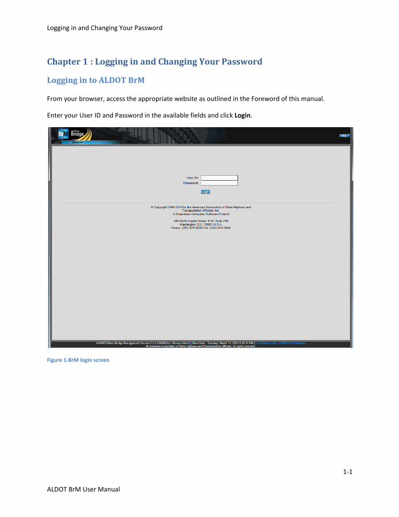
Once logged in, you will see the screen below. The first time you log in you will need to change your
password.
Figure 2 – BrM desktop
The header at the very top of the screen includes three buttons:
Help? – Click here to view the BrM help screen for the current screen.
Account – Click here to view your account information and to change your password.
Logout – Click here to quit BrM.
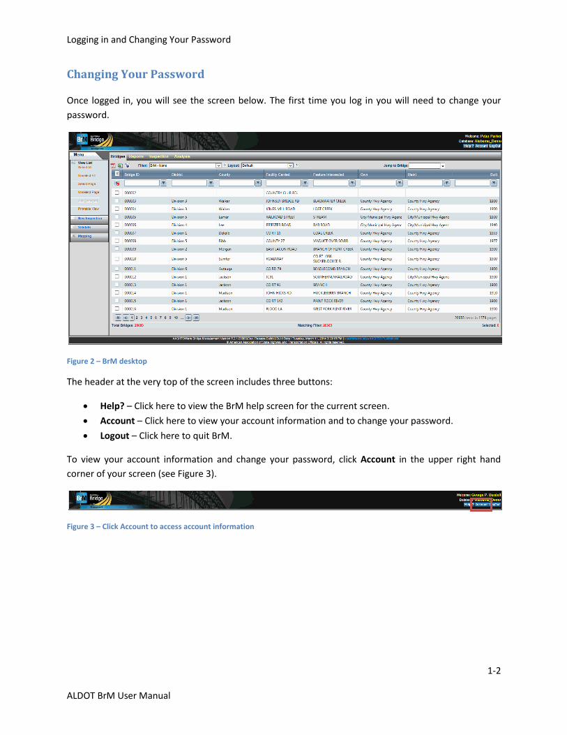
To view your account information and change your password, click Account in the upper right hand
corner of your screen (see Figure 3).
Figure 3 – Click Account to access account information
Logging in and Changing Your Password
1-3
ALDOT BrM User Manual
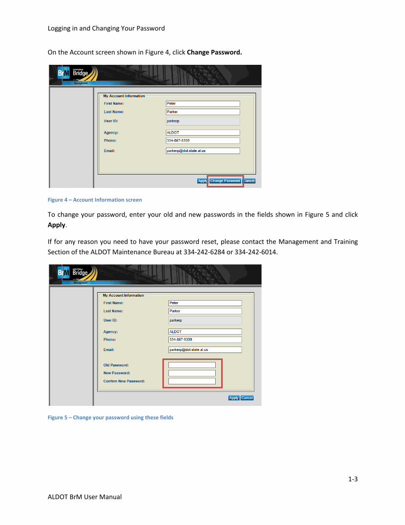
On the Account screen shown in Figure 4, click Change Password.
Figure 4 – Account Information screen
To change your password, enter your old and new passwords in the fields shown in Figure 5 and click
Apply.
If for any reason you need to have your password reset, please contact the Management and Training
Section of the ALDOT Maintenance Bureau at 334-242-6284 or 334-242-6014.
Figure 5 – Change your password using these fields

Logging in and Changing Your Password
1-4
ALDOT BrM User Manual
Site Layout
2-1
ALDOT BrM User Manual
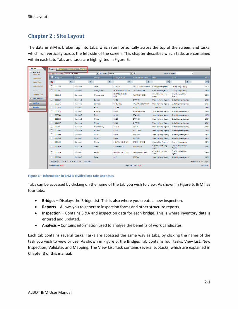
Chapter 2 : Site Layout
The data in BrM is broken up into tabs, which run horizontally across the top of the screen, and tasks,
which run vertically across the left side of the screen. This chapter describes which tasks are contained
within each tab. Tabs and tasks are highlighted in Figure 6.
Figure 6 – Information in BrM is divided into tabs and tasks
Tabs can be accessed by clicking on the name of the tab you wish to view. As shown in Figure 6, BrM has
four tabs:
Bridges – Displays the Bridge List. This is also where you create a new inspection.
Reports – Allows you to generate inspection forms and other structure reports.
Inspection – Contains SI&A and inspection data for each bridge. This is where inventory data is
entered and updated.
Analysis – Contains information used to analyze the benefits of work candidates.
Each tab contains several tasks. Tasks are accessed the same way as tabs, by clicking the name of the
task you wish to view or use. As shown in Figure 6, the Bridges Tab contains four tasks: View List, New
Inspection, Validate, and Mapping. The View List Task contains several subtasks, which are explained in
Chapter 3 of this manual.
Site Layout
2-2
ALDOT BrM User Manual
Site Map
The following is a list of tasks contained in each of the tabs. More information about each task can be
found in the following chapters of this manual:
Bridges
˗ View List
˗ New Inspection
˗ Validate
˗ Mapping
Reports
˗ Generate
Inspection
˗ Condition
˗ Appraisal
˗ Inventory
˗ Schedule
˗ Work
˗ Multimedia
˗ Element Condition Ratings
˗ Bridge Notes
˗ Replacement Program
˗ Structure Detail Observation
˗ Original Streambed Elevations
˗ Streambed Cross Sections
Analysis
˗ Work Candidates
˗ Utility Value
Bridges Tab-View List Task
3-1
ALDOT BrM User Manual
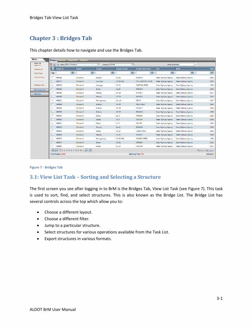
Chapter 3 : Bridges Tab
This chapter details how to navigate and use the Bridges Tab.
Figure 7 - Bridges Tab
3.1: View List Task – Sorting and Selecting a Structure
The first screen you see after logging in to BrM is the Bridges Tab, View List Task (see Figure 7). This task
is used to sort, find, and select structures. This is also known as the Bridge List. The Bridge List has
several controls across the top which allow you to:
Choose a different layout.
Choose a different filter.
Jump to a particular structure.
Select structures for various operations available from the Task List.
Export structures in various formats.
Bridges Tab-View List Task
3-2
ALDOT BrM User Manual
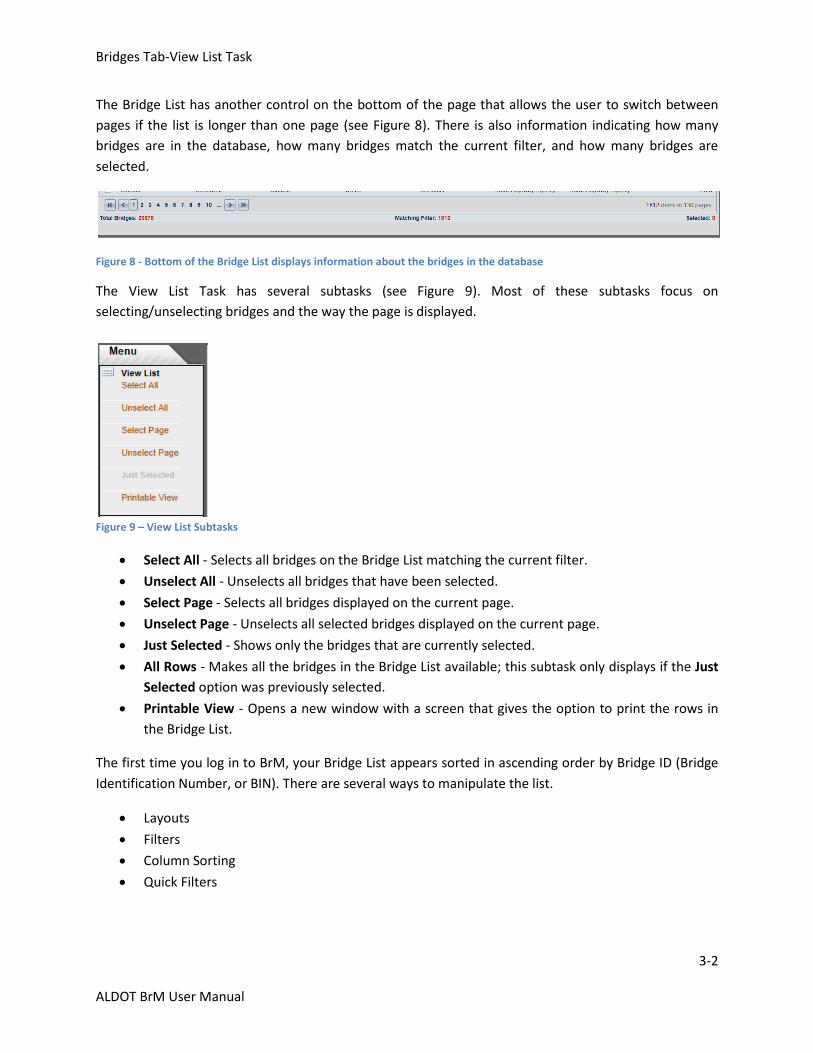
The Bridge List has another control on the bottom of the page that allows the user to switch between
pages if the list is longer than one page (see Figure 8). There is also information indicating how many
bridges are in the database, how many bridges match the current filter, and how many bridges are
selected.
Figure 8 - Bottom of the Bridge List displays information about the bridges in the database
The View List Task has several subtasks (see Figure 9). Most of these subtasks focus on
selecting/unselecting bridges and the way the page is displayed.
Figure 9 – View List Subtasks
Select All - Selects all bridges on the Bridge List matching the current filter.
Unselect All - Unselects all bridges that have been selected.
Select Page - Selects all bridges displayed on the current page.
Unselect Page - Unselects all selected bridges displayed on the current page.
Just Selected - Shows only the bridges that are currently selected.
All Rows - Makes all the bridges in the Bridge List available; this subtask only displays if the Just
Selected option was previously selected.
Printable View - Opens a new window with a screen that gives the option to print the rows in
the Bridge List.
The first time you log in to BrM, your Bridge List appears sorted in ascending order by Bridge ID (Bridge
Identification Number, or BIN). There are several ways to manipulate the list.
Layouts
Filters
Column Sorting
Quick Filters
Bridges Tab-View List Task
3-3
ALDOT BrM User Manual
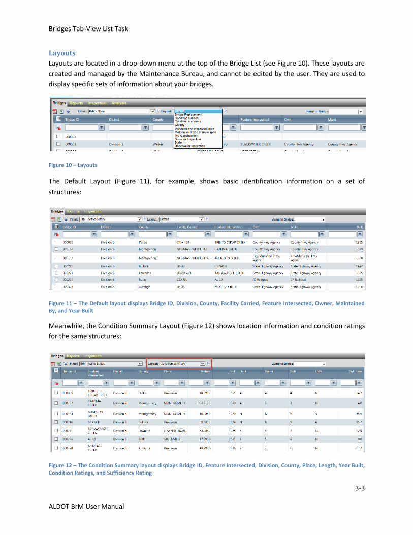
Layouts
Layouts are located in a drop-down menu at the top of the Bridge List (see Figure 10). These layouts are
created and managed by the Maintenance Bureau, and cannot be edited by the user. They are used to
display specific sets of information about your bridges.
Figure 10 – Layouts
The Default Layout (Figure 11), for example, shows basic identification information on a set of
structures:
Figure 11 – The Default layout displays Bridge ID, Division, County, Facility Carried, Feature Intersected, Owner, Maintained By, and Year Built
Meanwhile, the Condition Summary Layout (Figure 12) shows location information and condition ratings
for the same structures:
Figure 12 – The Condition Summary layout displays Bridge ID, Feature Intersected, Division, County, Place, Length, Year Built, Condition Ratings, and Sufficiency Rating
Bridges Tab-View List Task
3-4
ALDOT BrM User Manual
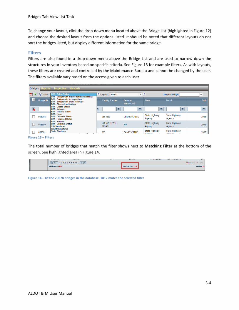
To change your layout, click the drop-down menu located above the Bridge List (highlighted in Figure 12)
and choose the desired layout from the options listed. It should be noted that different layouts do not
sort the bridges listed, but display different information for the same bridge.
Filters
Filters are also found in a drop-down menu above the Bridge List and are used to narrow down the
structures in your inventory based on specific criteria. See Figure 13 for example filters. As with layouts,
these filters are created and controlled by the Maintenance Bureau and cannot be changed by the user.
The filters available vary based on the access given to each user.
Figure 13 – Filters
The total number of bridges that match the filter shows next to Matching Filter at the bottom of the
screen. See highlighted area in Figure 14.
Figure 14 – Of the 20678 bridges in the database, 1812 match the selected filter

Bridges Tab-View List Task
3-5
ALDOT BrM User Manual
Column Sorting
You can also change the view of your Bridge List by sorting by any column displayed. Clicking a column
name sorts all bridges in the current filter by that field in ascending order. Clicking the column name
again sorts the bridges in descending order. Click the column name a third time to remove the sort. To
add a secondary sort, click on another column header. You can sort by as many columns as needed, and
the list sorts in the order you select the columns. The Bridge List in Figure 15 has been sorted by County
and Facility Carried, as shown in the red box:
Figure 15 – Bridge List sorted by County name, then Facility Carried
Quick Filters
As mentioned previously, the filters available in the drop-down menu are created by the Maintenance
Bureau. If you need to filter your bridges in a different way, there are dynamic quick filters available to
you. As shown in the highlighted area of Figure 16, quick filters are found in the row below the column
names:
Figure 16 – Quick filters can help you sort your bridge list dynamically
To use the quick filter, type in the filter criteria in the applicable field, click the filter icon next to the text
box, and choose the type of filter that applies to your search.
Listed below are a few examples of common filter types:
Filter Action
NoFilter Removes filter from column
EqualTo Returns only bridges where that column matches the search criteria exactly
NotEqualTo Returns all bridges where that column does not match exactly
Contains Returns all bridges where that column matches or contains the search criteria
Bridges Tab-View List Task
3-6
ALDOT BrM User Manual
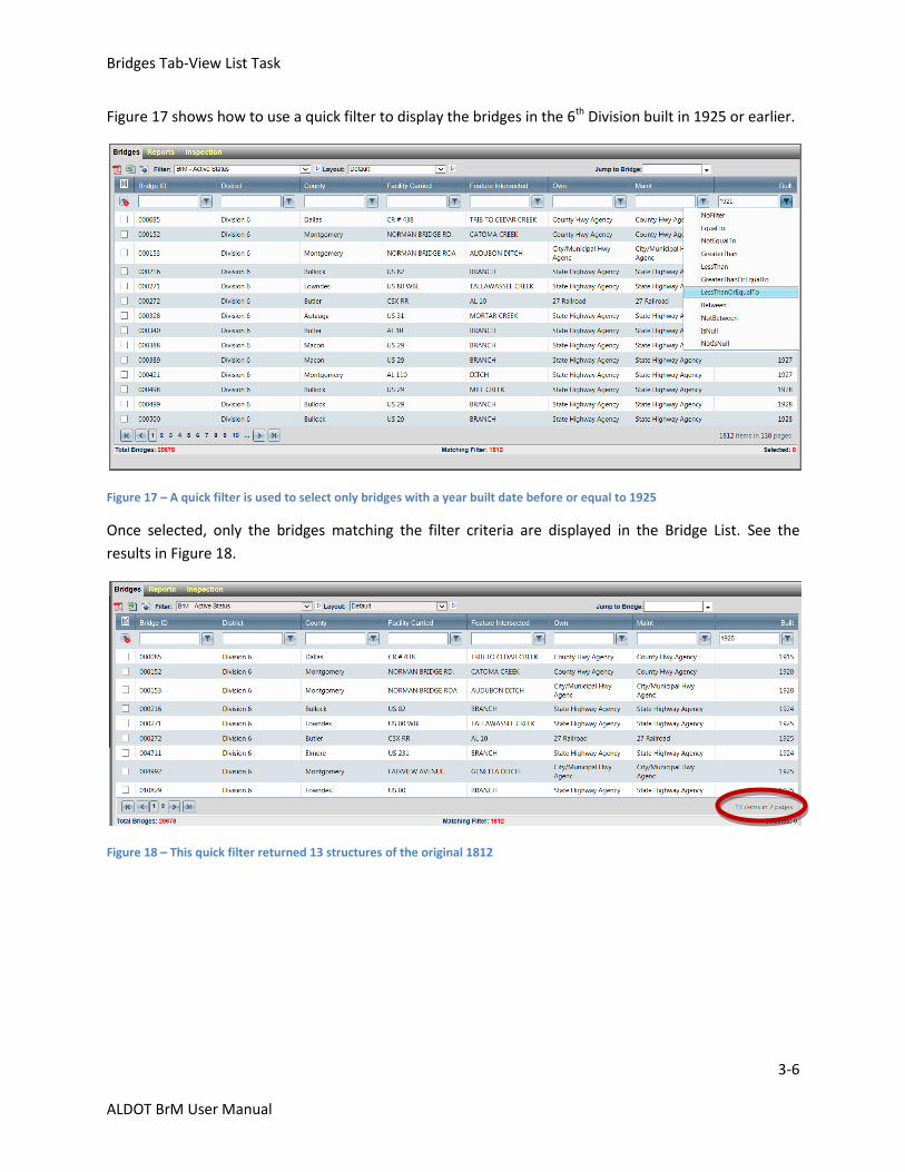
Figure 17 shows how to use a quick filter to display the bridges in the 6th Division built in 1925 or earlier.
Figure 17 – A quick filter is used to select only bridges with a year built date before or equal to 1925
Once selected, only the bridges matching the filter criteria are displayed in the Bridge List. See the
results in Figure 18.
Figure 18 – This quick filter returned 13 structures of the original 1812
Bridges Tab-View List Task
3-7
ALDOT BrM User Manual
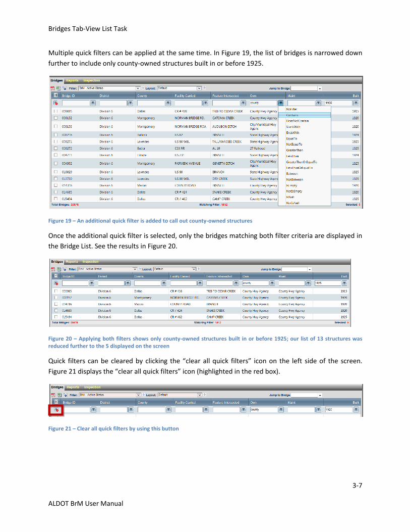
Multiple quick filters can be applied at the same time. In Figure 19, the list of bridges is narrowed down
further to include only county-owned structures built in or before 1925.
Figure 19 – An additional quick filter is added to call out county-owned structures
Once the additional quick filter is selected, only the bridges matching both filter criteria are displayed in
the Bridge List. See the results in Figure 20.
Figure 20 – Applying both filters shows only county-owned structures built in or before 1925; our list of 13 structures was reduced further to the 5 displayed on the screen
Quick filters can be cleared by clicking the “clear all quick filters” icon on the left side of the screen.
Figure 21 displays the “clear all quick filters” icon (highlighted in the red box).
Figure 21 – Clear all quick filters by using this button
Bridges Tab-View List Task
3-8
ALDOT BrM User Manual
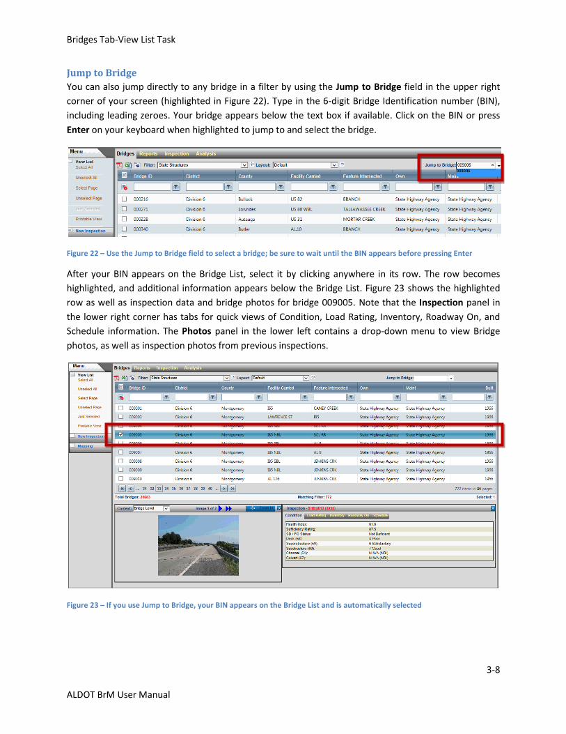
Jump to Bridge
You can also jump directly to any bridge in a filter by using the Jump to Bridge field in the upper right
corner of your screen (highlighted in Figure 22). Type in the 6-digit Bridge Identification number (BIN),
including leading zeroes. Your bridge appears below the text box if available. Click on the BIN or press
Enter on your keyboard when highlighted to jump to and select the bridge.
Figure 22 – Use the Jump to Bridge field to select a bridge; be sure to wait until the BIN appears before pressing Enter
After your BIN appears on the Bridge List, select it by clicking anywhere in its row. The row becomes
highlighted, and additional information appears below the Bridge List. Figure 23 shows the highlighted
row as well as inspection data and bridge photos for bridge 009005. Note that the Inspection panel in
the lower right corner has tabs for quick views of Condition, Load Rating, Inventory, Roadway On, and
Schedule information. The Photos panel in the lower left contains a drop-down menu to view Bridge
photos, as well as inspection photos from previous inspections.
Figure 23 – If you use Jump to Bridge, your BIN appears on the Bridge List and is automatically selected
Bridges Tab-View List Task
3-9
ALDOT BrM User Manual
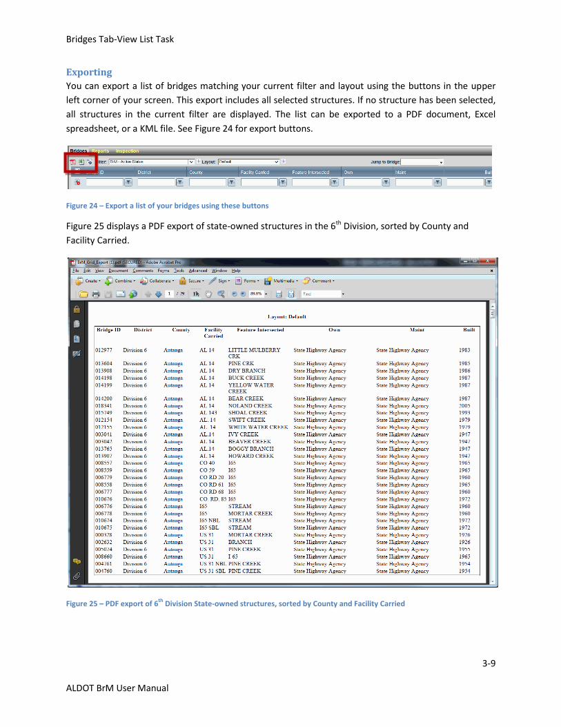
Exporting
You can export a list of bridges matching your current filter and layout using the buttons in the upper
left corner of your screen. This export includes all selected structures. If no structure has been selected,
all structures in the current filter are displayed. The list can be exported to a PDF document, Excel
spreadsheet, or a KML file. See Figure 24 for export buttons.
Figure 24 – Export a list of your bridges using these buttons
Figure 25 displays a PDF export of state-owned structures in the 6th Division, sorted by County and
Facility Carried.
Figure 25 – PDF export of 6th
Division State-owned structures, sorted by County and Facility Carried
Bridges Tab-Creating a New Inspection
3-10
ALDOT BrM User Manual
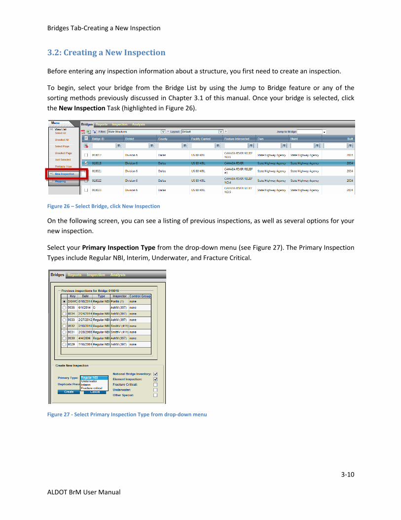
3.2: Creating a New Inspection
Before entering any inspection information about a structure, you first need to create an inspection.
To begin, select your bridge from the Bridge List by using the Jump to Bridge feature or any of the
sorting methods previously discussed in Chapter 3.1 of this manual. Once your bridge is selected, click
the New Inspection Task (highlighted in Figure 26).
Figure 26 – Select Bridge, click New Inspection
On the following screen, you can see a listing of previous inspections, as well as several options for your
new inspection.
Select your Primary Inspection Type from the drop-down menu (see Figure 27). The Primary Inspection
Types include Regular NBI, Interim, Underwater, and Fracture Critical.
Figure 27 - Select Primary Inspection Type from drop-down menu
Bridges Tab-Creating a New Inspection
3-11
ALDOT BrM User Manual
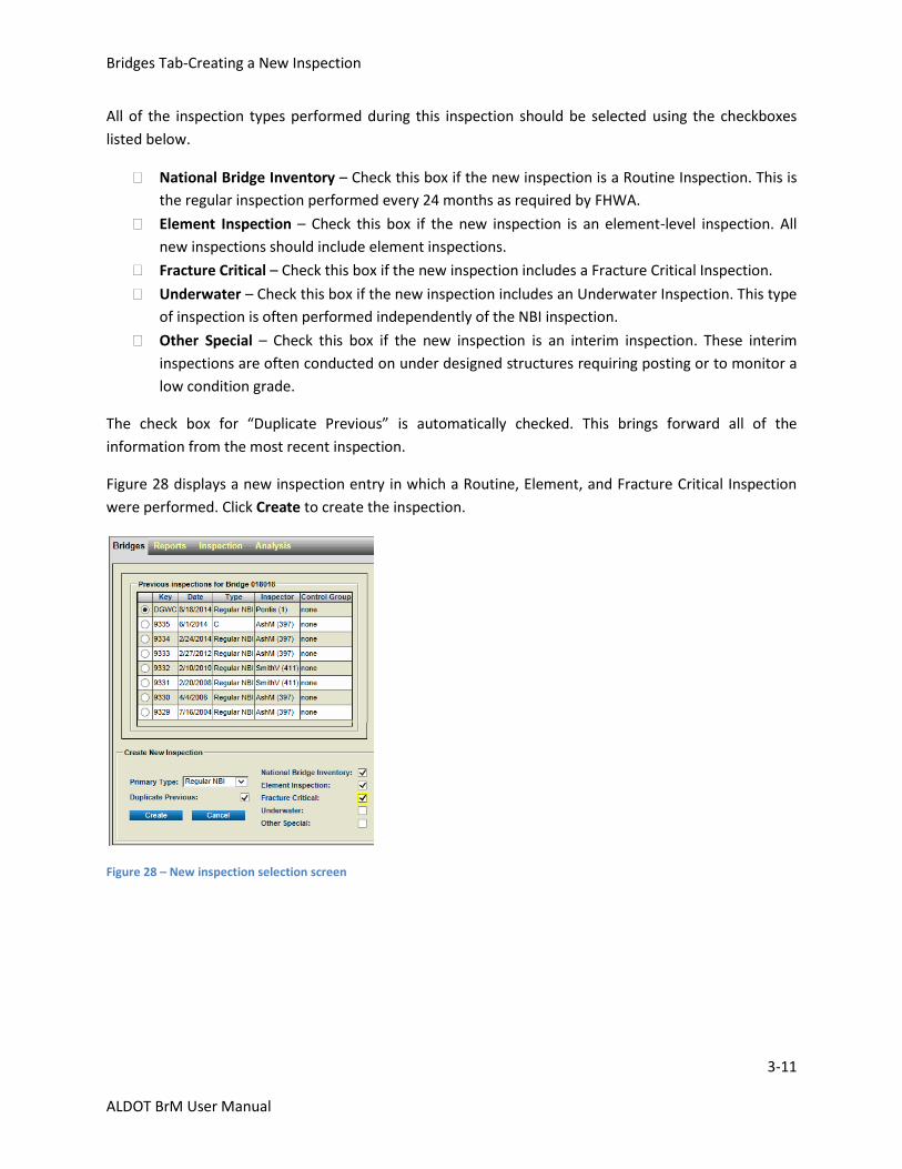
All of the inspection types performed during this inspection should be selected using the checkboxes
listed below.
National Bridge Inventory – Check this box if the new inspection is a Routine Inspection. This is
the regular inspection performed every 24 months as required by FHWA.
Element Inspection – Check this box if the new inspection is an element-level inspection. All
new inspections should include element inspections.
Fracture Critical – Check this box if the new inspection includes a Fracture Critical Inspection.
Underwater – Check this box if the new inspection includes an Underwater Inspection. This type
of inspection is often performed independently of the NBI inspection.
Other Special – Check this box if the new inspection is an interim inspection. These interim
inspections are often conducted on under designed structures requiring posting or to monitor a
low condition grade.
The check box for “Duplicate Previous” is automatically checked. This brings forward all of the
information from the most recent inspection.
Figure 28 displays a new inspection entry in which a Routine, Element, and Fracture Critical Inspection
were performed. Click Create to create the inspection.
Figure 28 – New inspection selection screen
Bridges Tab-Creating a New Inspection
3-12
ALDOT BrM User Manual
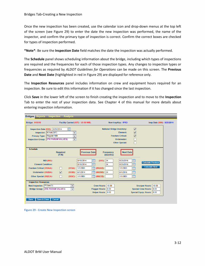
Once the new inspection has been created, use the calendar icon and drop-down menus at the top left
of the screen (see Figure 29) to enter the date the new inspection was performed, the name of the
inspector, and confirm the primary type of inspection is correct. Confirm the correct boxes are checked
for types of inspection performed.
*Note*: Be sure the Inspection Date field matches the date the inspection was actually performed.
The Schedule panel shows scheduling information about the bridge, including which types of inspections
are required and the frequencies for each of those inspection types. Any changes to inspection types or
frequencies as required by ALDOT Guidelines for Operations can be made on this screen. The Previous
Date and Next Date (highlighted in red in Figure 29) are displayed for reference only.
The Inspection Resources panel includes information on crew and equipment hours required for an
inspection. Be sure to edit this information if it has changed since the last inspection.
Click Save in the lower left of the screen to finish creating the inspection and to move to the Inspection
Tab to enter the rest of your inspection data. See Chapter 4 of this manual for more details about
entering inspection information.
Figure 29 - Create New Inspection screen
Bridges Tab-Validate Task
3-13
ALDOT BrM User Manual
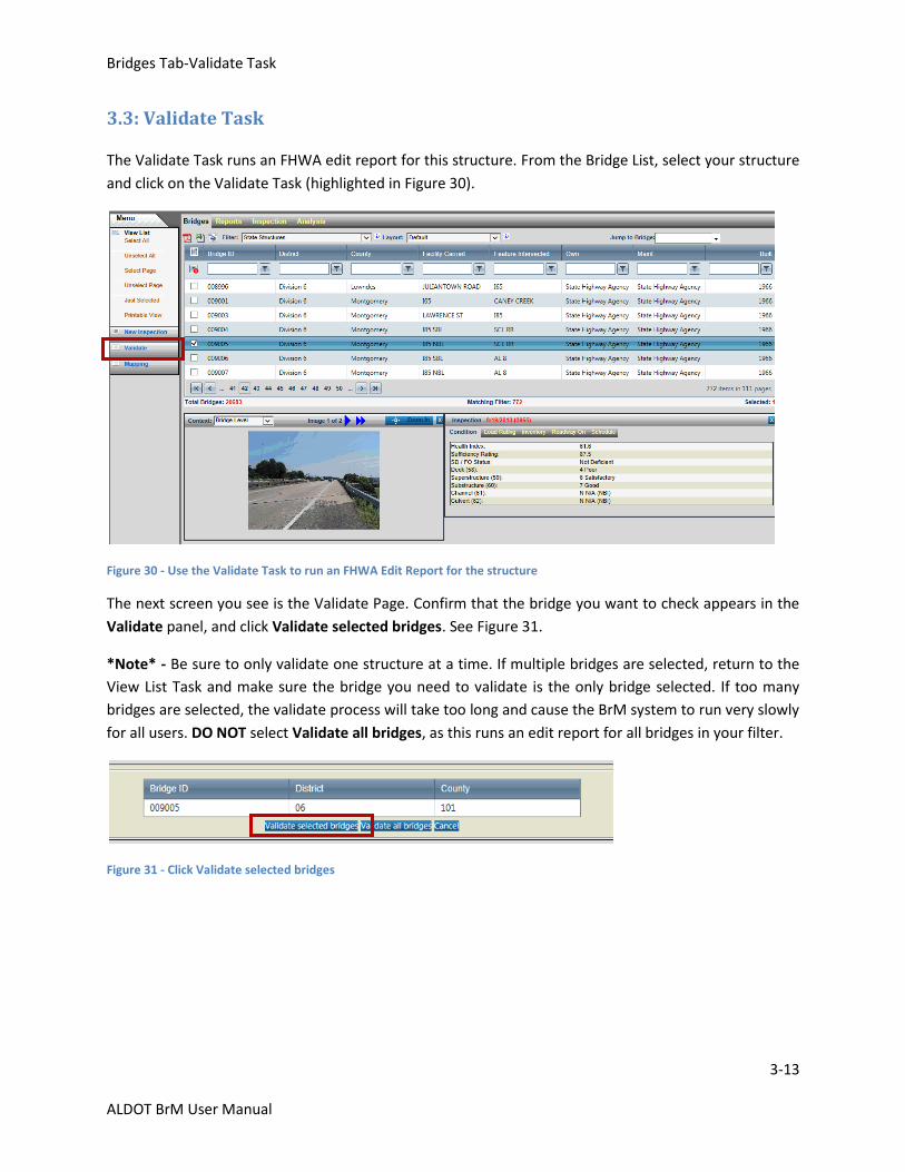
3.3: Validate Task
The Validate Task runs an FHWA edit report for this structure. From the Bridge List, select your structure
and click on the Validate Task (highlighted in Figure 30).
Figure 30 - Use the Validate Task to run an FHWA Edit Report for the structure
The next screen you see is the Validate Page. Confirm that the bridge you want to check appears in the
Validate panel, and click Validate selected bridges. See Figure 31.
*Note* - Be sure to only validate one structure at a time. If multiple bridges are selected, return to the
View List Task and make sure the bridge you need to validate is the only bridge selected. If too many
bridges are selected, the validate process will take too long and cause the BrM system to run very slowly
for all users. DO NOT select Validate all bridges, as this runs an edit report for all bridges in your filter.
Figure 31 - Click Validate selected bridges
Bridges Tab-Validate Task
3-14
ALDOT BrM User Manual
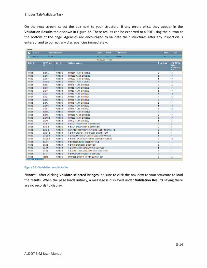
On the next screen, select the box next to your structure. If any errors exist, they appear in the
Validation Results table shown in Figure 32. These results can be exported to a PDF using the button at
the bottom of the page. Agencies are encouraged to validate their structures after any inspection is
entered, and to correct any discrepancies immediately.
Figure 32 - Validation results table
*Note* - after clicking Validate selected bridges, be sure to click the box next to your structure to load
the results. When the page loads initially, a message is displayed under Validation Results saying there
are no records to display.
Bridges Tab-Mapping Task
3-15
ALDOT BrM User Manual
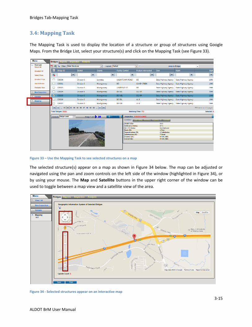
3.4: Mapping Task
The Mapping Task is used to display the location of a structure or group of structures using Google
Maps. From the Bridge List, select your structure(s) and click on the Mapping Task (see Figure 33).
Figure 33 – Use the Mapping Task to see selected structures on a map
The selected structure(s) appear on a map as shown in Figure 34 below. The map can be adjusted or
navigated using the pan and zoom controls on the left side of the window (highlighted in Figure 34), or
by using your mouse. The Map and Satellite buttons in the upper right corner of the window can be
used to toggle between a map view and a satellite view of the area.
Figure 34 - Selected structures appear on an interactive map
Bridges Tab-Mapping Task
3-16
ALDOT BrM User Manual
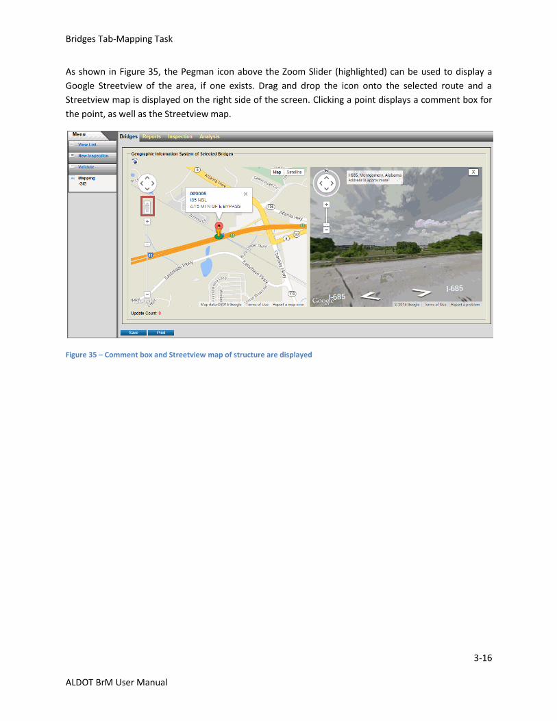
As shown in Figure 35, the Pegman icon above the Zoom Slider (highlighted) can be used to display a
Google Streetview of the area, if one exists. Drag and drop the icon onto the selected route and a
Streetview map is displayed on the right side of the screen. Clicking a point displays a comment box for
the point, as well as the Streetview map.
Figure 35 – Comment box and Streetview map of structure are displayed
Inspection Tab
4-1
ALDOT BrM User Manual
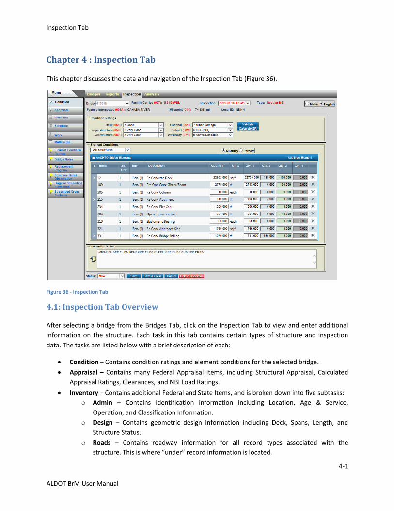
Chapter 4 : Inspection Tab
This chapter discusses the data and navigation of the Inspection Tab (Figure 36).
Figure 36 - Inspection Tab
4.1: Inspection Tab Overview
After selecting a bridge from the Bridges Tab, click on the Inspection Tab to view and enter additional
information on the structure. Each task in this tab contains certain types of structure and inspection
data. The tasks are listed below with a brief description of each:
Condition – Contains condition ratings and element conditions for the selected bridge.
Appraisal – Contains many Federal Appraisal Items, including Structural Appraisal, Calculated
Appraisal Ratings, Clearances, and NBI Load Ratings.
Inventory – Contains additional Federal and State Items, and is broken down into five subtasks:
o Admin – Contains identification information including Location, Age & Service,
Operation, and Classification Information.
o Design – Contains geometric design information including Deck, Spans, Length, and
Structure Status.
o Roads – Contains roadway information for all record types associated with the
structure. This is where “under” record information is located.

Inspection Tab
4-2
ALDOT BrM User Manual
o Identification – Contains many State Items including Agency Identification, Inspection
details, and Agency Load Rating information.
o State Items – Contains additional State Items including Culvert, Paint, and Type.
Schedule – Contains NBI scheduling information, including types, dates, and frequencies of
inspection.
Work – Contains information related to work candidates and accomplishments, and is broken
down into several subtasks:
o Work Candidates – Contains information on any work candidates.
o Project Information – Contains bridge project planning information.
o Accomplishments – Displays completed work events.
Multimedia – Contains multimedia information, including photographs and documents.
Element Condition Ratings – Displays Element and Condition Ratings for all past inspections.
Bridge Notes – Contains General, Scour, Rating, Program, and EBIT notes about the bridge.
Replacement Program – Displays information related to prioritizing bridges for replacement.
Structure Detail Observation – Contains structure details to be displayed on scour plots.
Original Streambed Elevations – Contains original streambed elevations to be displayed on
scour plots.
Streambed Cross Sections – Contains streambed cross section data to be displayed on scour
plots.
Each task in the Inspection Tab displays a header (see Figure 37) which includes read-only identification
information: Facility Carried, Feature Intersected, Mile point, and Local ID.
Figure 37 - Typical header for a task in the Inspection Tab
The Bridge field works just like Jump to Bridge on the View List Task. Type in the 6-digit BIN of a
structure to jump directly to the task currently displayed for that bridge.
Some of the information on the task screen pertains to particular inspections, while other information
pertains to the bridge itself. The Inspection: drop-down list in the header allows you to view data from
previous inspections. The Type: field shows the primary type of the inspection selected. When the task
is opened, the most recent inspection is shown by default. When entering data, you need to confirm the
correct date is displayed in this drop-down. The header also includes radio buttons to select English or
Metric units.
Many tasks also feature a footer (Figure 38):
Figure 38 - Typical footer for a task in the Inspection Tab
Inspection Tab
4-3
ALDOT BrM User Manual
The footer contains the following buttons:
Status - This field contains items in the drop-down menu but will not be used at this time.
Save – Saves all changes.
Save & Close – Saves all changes and returns you to the Bridges List.
Cancel – Cancels all changes and resets the screen to its previously saved state.
Delete Inspection – Is only visible on some screens and deletes the selected inspection and all
its related content from the database.
After changing any field in a task, the field displays a yellow background until changes are saved.
Inspection Tab-Condition Task
4-4
ALDOT BrM User Manual
4.2: Condition Task
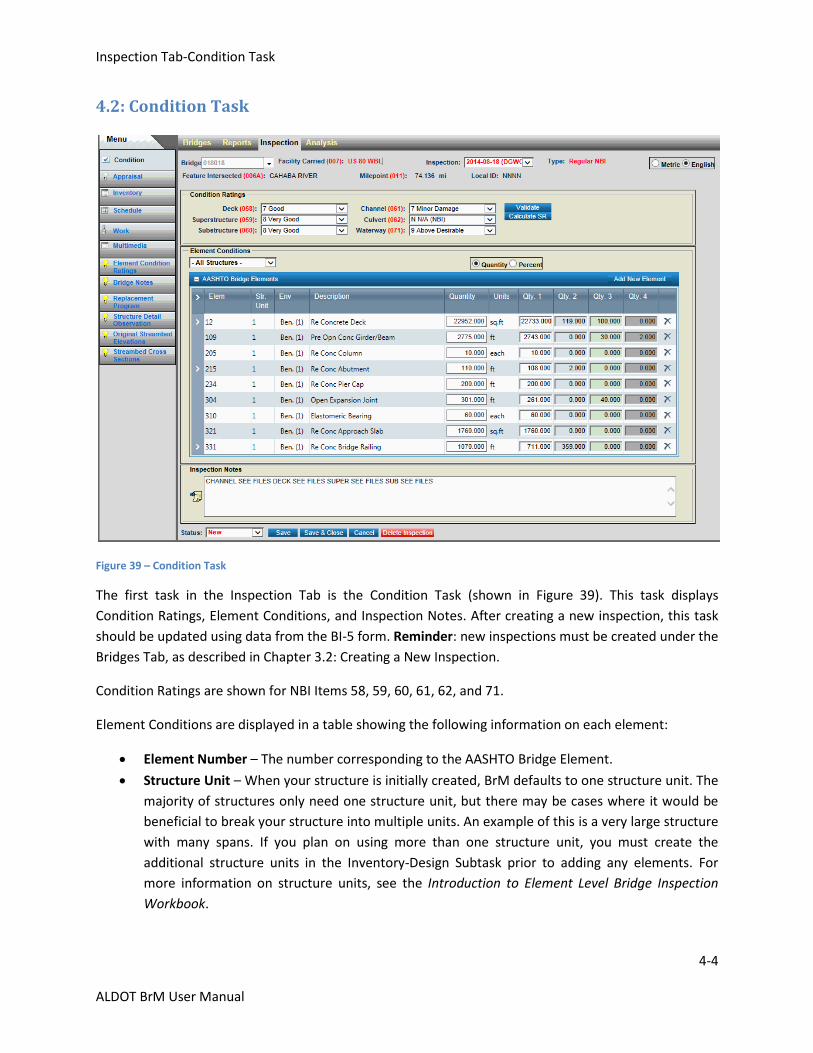
Figure 39 – Condition Task
The first task in the Inspection Tab is the Condition Task (shown in Figure 39). This task displays
Condition Ratings, Element Conditions, and Inspection Notes. After creating a new inspection, this task
should be updated using data from the BI-5 form. Reminder: new inspections must be created under the
Bridges Tab, as described in Chapter 3.2: Creating a New Inspection.
Condition Ratings are shown for NBI Items 58, 59, 60, 61, 62, and 71.
Element Conditions are displayed in a table showing the following information on each element:
Element Number – The number corresponding to the AASHTO Bridge Element.
Structure Unit – When your structure is initially created, BrM defaults to one structure unit. The
majority of structures only need one structure unit, but there may be cases where it would be
beneficial to break your structure into multiple units. An example of this is a very large structure
with many spans. If you plan on using more than one structure unit, you must create the
additional structure units in the Inventory-Design Subtask prior to adding any elements. For
more information on structure units, see the Introduction to Element Level Bridge Inspection
Workbook.
Inspection Tab-Condition Task
4-5
ALDOT BrM User Manual
Environment – The majority of structures in the state of Alabama fall into Environment 1-
Benign. Those subjected to salt spray or road salt may need to use another environment. For
more information about Environments, see the Introduction to Element Level Bridge Inspection
Workbook.
Description – A descriptive name given to the AASHTO Bridge Element.
Quantity – The total quantity or count of the element.
Units – The type of units associated with the element.
Qty. 1-4 – These refer to the Condition States for each element. When an element is added, the
entire quantity is automatically placed in Qty. 1.
This table also includes defects and protective systems, which are nested under their associated
elements. To view these, click the arrow next to the element number, or you can click the arrow at the
top left corner of the table to expand all items in the table. An element without an entered defect or
protective system does not have an arrow next to the element number.
Element Conditions can be displayed by quantity or by percent using the radio buttons above the table.
If previous inspections exist, you can click the Inspection: drop-down at the top of the screen and select
another inspection to see previous condition ratings. To see a complete history of condition ratings for a
bridge, see the Element Conditions Ratings Task.
General notes relating to this inspection are displayed in the Inspection Notes panel. Notes associated
with specific elements are displayed within the Element Condition panel when an element is selected.
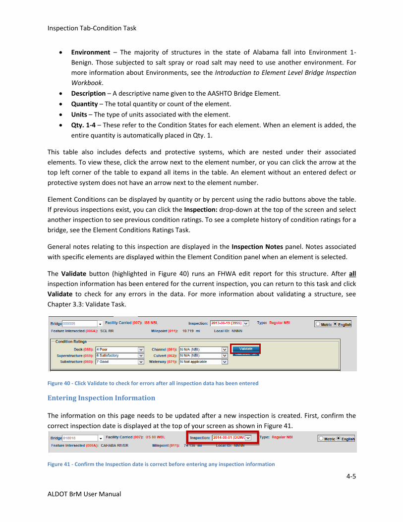
The Validate button (highlighted in Figure 40) runs an FHWA edit report for this structure. After all
inspection information has been entered for the current inspection, you can return to this task and click
Validate to check for any errors in the data. For more information about validating a structure, see
Chapter 3.3: Validate Task.
Figure 40 - Click Validate to check for errors after all inspection data has been entered
Entering Inspection Information
The information on this page needs to be updated after a new inspection is created. First, confirm the
correct inspection date is displayed at the top of your screen as shown in Figure 41.
Figure 41 - Confirm the Inspection date is correct before entering any inspection information
Inspection Tab-Condition Task
4-6
ALDOT BrM User Manual
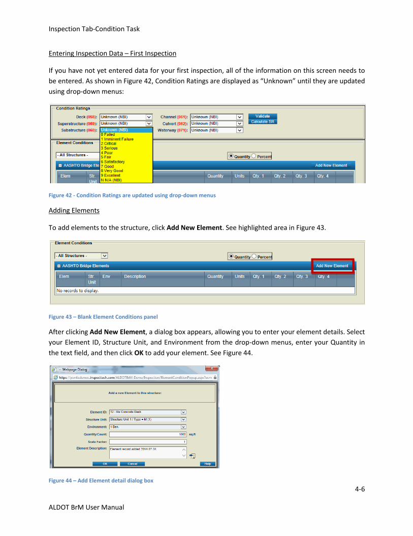
Entering Inspection Data – First Inspection
If you have not yet entered data for your first inspection, all of the information on this screen needs to
be entered. As shown in Figure 42, Condition Ratings are displayed as “Unknown” until they are updated
using drop-down menus:
Figure 42 - Condition Ratings are updated using drop-down menus
Adding Elements
To add elements to the structure, click Add New Element. See highlighted area in Figure 43.
Figure 43 – Blank Element Conditions panel
After clicking Add New Element, a dialog box appears, allowing you to enter your element details. Select
your Element ID, Structure Unit, and Environment from the drop-down menus, enter your Quantity in
the text field, and then click OK to add your element. See Figure 44.
Figure 44 – Add Element detail dialog box

Inspection Tab-Condition Task
4-7
ALDOT BrM User Manual
The new element then appears in the Element Conditions panel and the entire quantity is displayed in
Qty. 1 as shown in Figure 45.
Figure 45 – A new element has been added to the table
It is possible to assign portions of the total quantity to different condition states (Qty. 1 represents the
quantity in condition state 1, Qty. 2 represents the amount in condition state 2, etc.). In order to move
the quantity out of condition state 1, click in Qty. 2. Delete the “0”, and then enter the appropriate
amount. Next, either tab out of the field or use the mouse to click out of the box. Qty. 1 is updated
automatically as the other quantities are changed. Figure 46 shows 1000 square feet of reinforced
concrete deck, with 200 square feet in condition state 2 and the rest in condition state 1.
Figure 46 – When part of the element is moved to another condition state, the first condition state updates automatically
Inspection Tab-Condition Task
4-8
ALDOT BrM User Manual
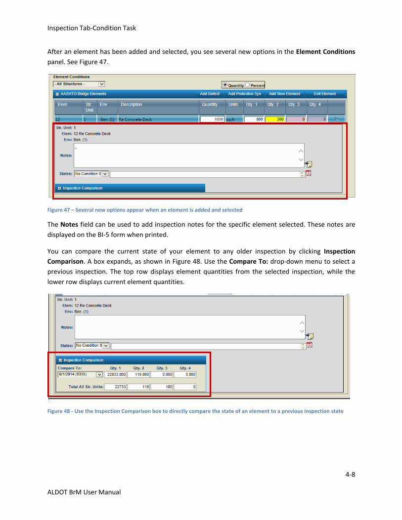
After an element has been added and selected, you see several new options in the Element Conditions
panel. See Figure 47.
Figure 47 – Several new options appear when an element is added and selected
The Notes field can be used to add inspection notes for the specific element selected. These notes are
displayed on the BI-5 form when printed.
You can compare the current state of your element to any older inspection by clicking Inspection
Comparison. A box expands, as shown in Figure 48. Use the Compare To: drop-down menu to select a
previous inspection. The top row displays element quantities from the selected inspection, while the
lower row displays current element quantities.
Figure 48 - Use the Inspection Comparison box to directly compare the state of an element to a previous inspection state
Inspection Tab-Condition Task
4-9
ALDOT BrM User Manual
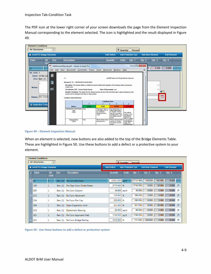
The PDF icon at the lower right corner of your screen downloads the page from the Element Inspection
Manual corresponding to the element selected. The icon is highlighted and the result displayed in Figure
49.
Figure 49 – Element Inspection Manual
When an element is selected, new buttons are also added to the top of the Bridge Elements Table.
These are highlighted in Figure 50. Use these buttons to add a defect or a protective system to your
element.
Figure 50 - Use these buttons to add a defect or protective system
Inspection Tab-Condition Task
4-10
ALDOT BrM User Manual
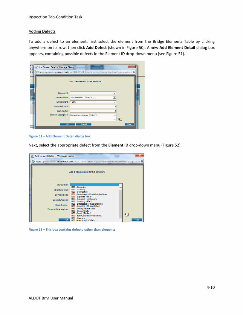
Adding Defects
To add a defect to an element, first select the element from the Bridge Elements Table by clicking
anywhere on its row, then click Add Defect (shown in Figure 50). A new Add Element Detail dialog box
appears, containing possible defects in the Element ID drop-down menu (see Figure 51).
Figure 51 – Add Element Detail dialog box
Next, select the appropriate defect from the Element ID drop-down menu (Figure 52).
Figure 52 – This box contains defects rather than elements
Inspection Tab-Condition Task
4-11
ALDOT BrM User Manual
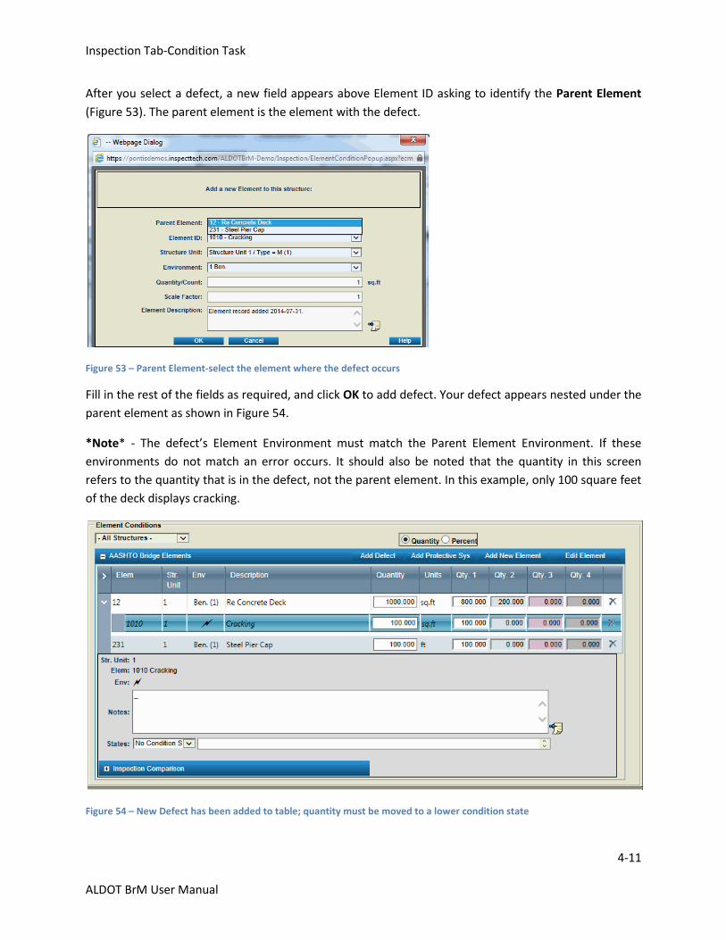
After you select a defect, a new field appears above Element ID asking to identify the Parent Element
(Figure 53). The parent element is the element with the defect.
Figure 53 – Parent Element-select the element where the defect occurs
Fill in the rest of the fields as required, and click OK to add defect. Your defect appears nested under the
parent element as shown in Figure 54.
*Note* - The defect’s Element Environment must match the Parent Element Environment. If these
environments do not match an error occurs. It should also be noted that the quantity in this screen
refers to the quantity that is in the defect, not the parent element. In this example, only 100 square feet
of the deck displays cracking.
Figure 54 – New Defect has been added to table; quantity must be moved to a lower condition state
Inspection Tab-Condition Task
4-12
ALDOT BrM User Manual
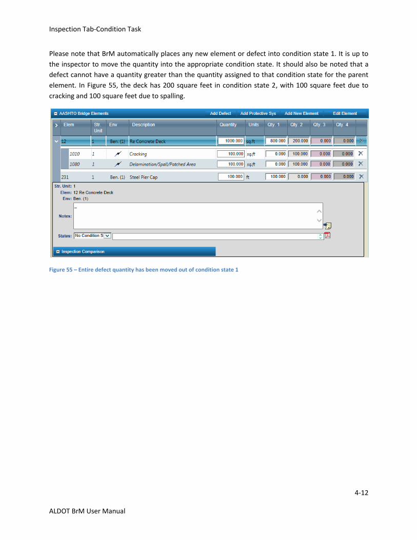
Please note that BrM automatically places any new element or defect into condition state 1. It is up to
the inspector to move the quantity into the appropriate condition state. It should also be noted that a
defect cannot have a quantity greater than the quantity assigned to that condition state for the parent
element. In Figure 55, the deck has 200 square feet in condition state 2, with 100 square feet due to
cracking and 100 square feet due to spalling.
Figure 55 – Entire defect quantity has been moved out of condition state 1
Inspection Tab-Condition Task
4-13
ALDOT BrM User Manual
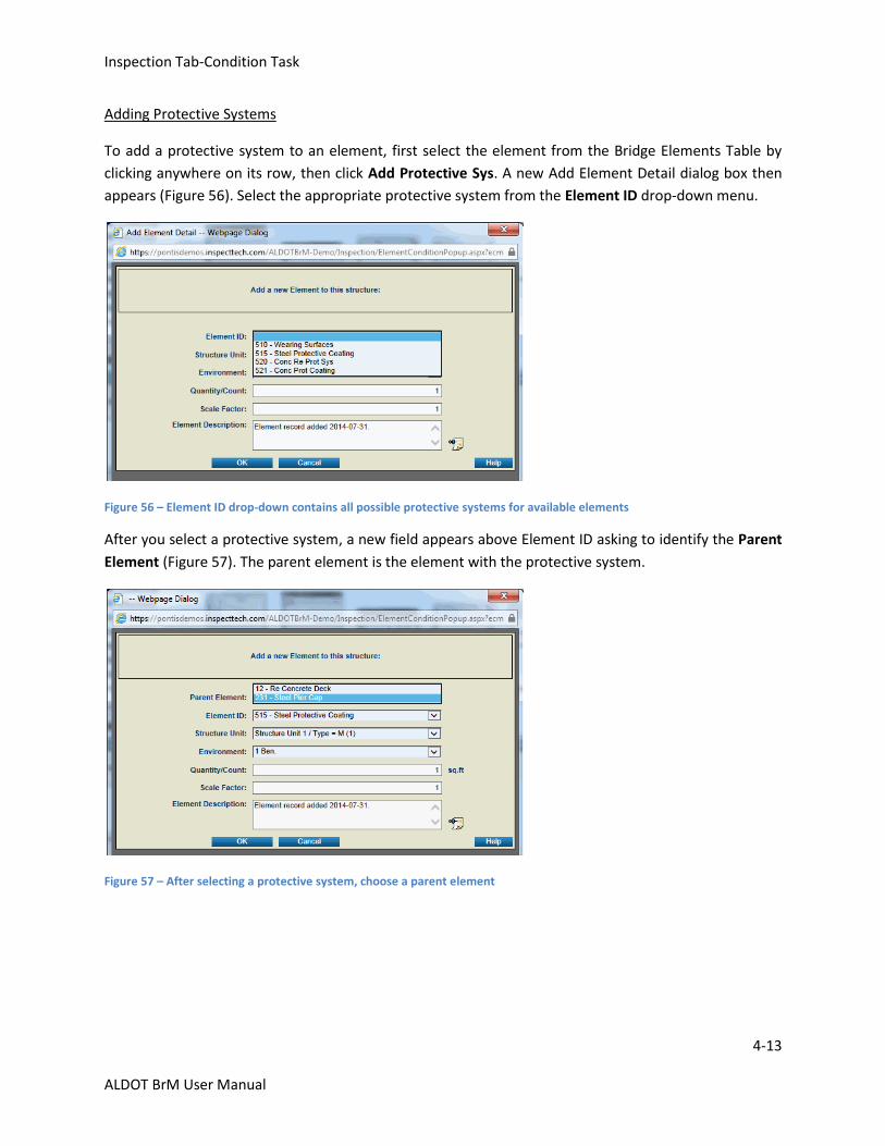
Adding Protective Systems
To add a protective system to an element, first select the element from the Bridge Elements Table by
clicking anywhere on its row, then click Add Protective Sys. A new Add Element Detail dialog box then
appears (Figure 56). Select the appropriate protective system from the Element ID drop-down menu.
Figure 56 – Element ID drop-down contains all possible protective systems for available elements
After you select a protective system, a new field appears above Element ID asking to identify the Parent
Element (Figure 57). The parent element is the element with the protective system.
Figure 57 – After selecting a protective system, choose a parent element
Inspection Tab-Condition Task
4-14
ALDOT BrM User Manual
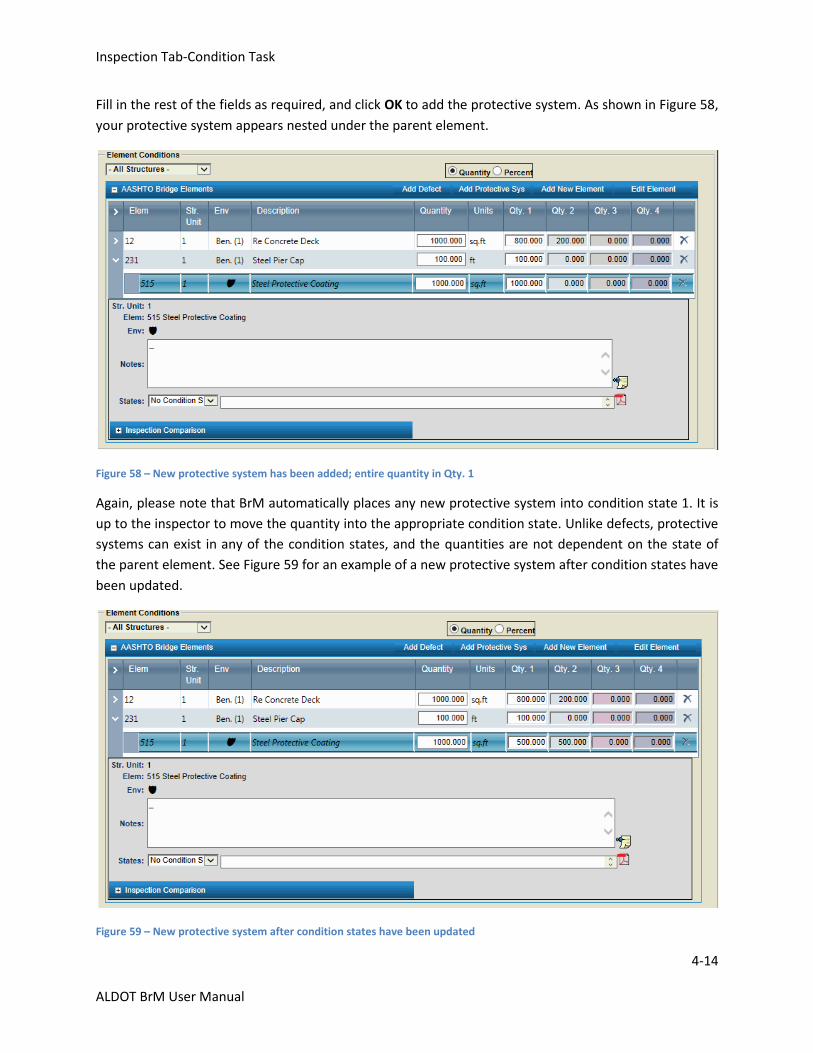
Fill in the rest of the fields as required, and click OK to add the protective system. As shown in Figure 58,
your protective system appears nested under the parent element.
Figure 58 – New protective system has been added; entire quantity in Qty. 1
Again, please note that BrM automatically places any new protective system into condition state 1. It is
up to the inspector to move the quantity into the appropriate condition state. Unlike defects, protective
systems can exist in any of the condition states, and the quantities are not dependent on the state of
the parent element. See Figure 59 for an example of a new protective system after condition states have
been updated.
Figure 59 – New protective system after condition states have been updated
Inspection Tab-Condition Task
4-15
ALDOT BrM User Manual
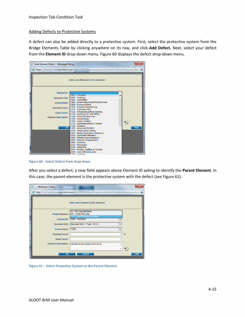
Adding Defects to Protective Systems
A defect can also be added directly to a protective system. First, select the protective system from the
Bridge Elements Table by clicking anywhere on its row, and click Add Defect. Next, select your defect
from the Element ID drop-down menu. Figure 60 displays the defect drop-down menu.
Figure 60 - Select Defect from drop-down
After you select a defect, a new field appears above Element ID asking to identify the Parent Element. In
this case, the parent element is the protective system with the defect (see Figure 61).
Figure 61 – Select Protective System as the Parent Element
Inspection Tab-Condition Task
4-16
ALDOT BrM User Manual
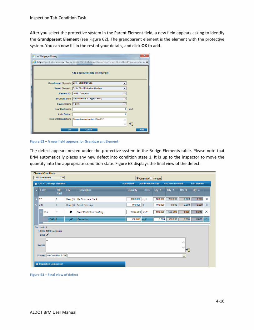
After you select the protective system in the Parent Element field, a new field appears asking to identify
the Grandparent Element (see Figure 62). The grandparent element is the element with the protective
system. You can now fill in the rest of your details, and click OK to add.
Figure 62 – A new field appears for Grandparent Element
The defect appears nested under the protective system in the Bridge Elements table. Please note that
BrM automatically places any new defect into condition state 1. It is up to the inspector to move the
quantity into the appropriate condition state. Figure 63 displays the final view of the defect.
Figure 63 – Final view of defect
Inspection Tab-Condition Task
4-17
ALDOT BrM User Manual
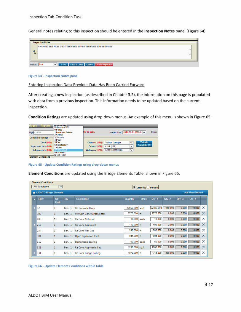
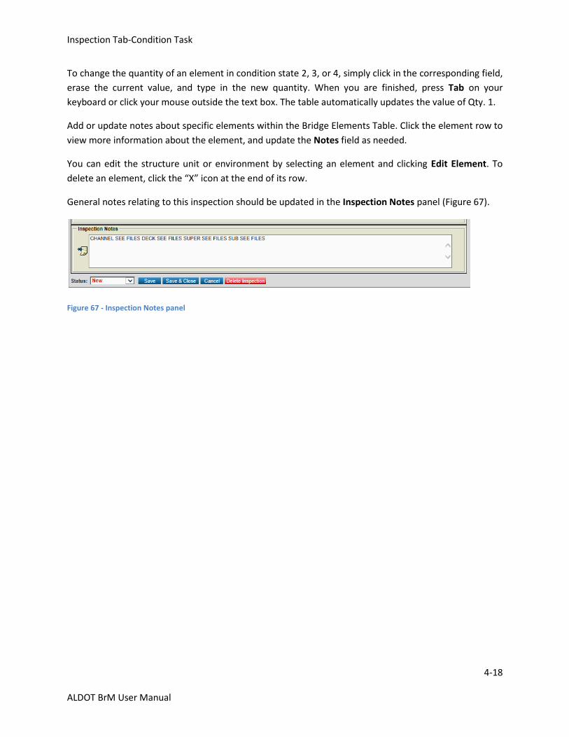
General notes relating to this inspection should be entered in the Inspection Notes panel (Figure 64).
Figure 64 - Inspection Notes panel
Entering Inspection Data-Previous Data Has Been Carried Forward
After creating a new inspection (as described in Chapter 3.2), the information on this page is populated
with data from a previous inspection. This information needs to be updated based on the current
inspection.
Condition Ratings are updated using drop-down menus. An example of this menu is shown in Figure 65.
Figure 65 - Update Condition Ratings using drop-down menus
Element Conditions are updated using the Bridge Elements Table, shown in Figure 66.
Figure 66 - Update Element Conditions within table
Inspection Tab-Condition Task
4-18
ALDOT BrM User Manual
To change the quantity of an element in condition state 2, 3, or 4, simply click in the corresponding field,
erase the current value, and type in the new quantity. When you are finished, press Tab on your
keyboard or click your mouse outside the text box. The table automatically updates the value of Qty. 1.
Add or update notes about specific elements within the Bridge Elements Table. Click the element row to
view more information about the element, and update the Notes field as needed.
You can edit the structure unit or environment by selecting an element and clicking Edit Element. To
delete an element, click the “X” icon at the end of its row.
General notes relating to this inspection should be updated in the Inspection Notes panel (Figure 67).
Figure 67 - Inspection Notes panel
Inspection Tab-Appraisal Task
4-19
ALDOT BrM User Manual
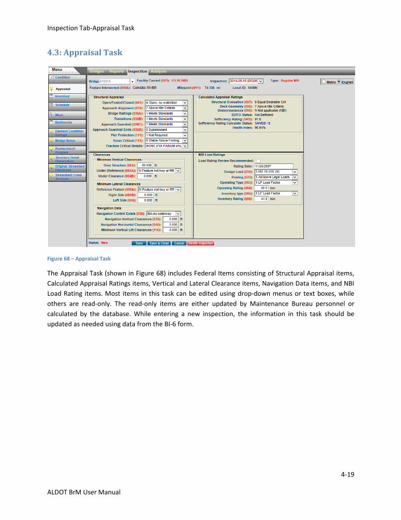
4.3: Appraisal Task
Figure 68 – Appraisal Task
The Appraisal Task (shown in Figure 68) includes Federal Items consisting of Structural Appraisal items,
Calculated Appraisal Ratings items, Vertical and Lateral Clearance items, Navigation Data items, and NBI
Load Rating items. Most items in this task can be edited using drop-down menus or text boxes, while
others are read-only. The read-only items are either updated by Maintenance Bureau personnel or
calculated by the database. While entering a new inspection, the information in this task should be
updated as needed using data from the BI-6 form.
Inspection Tab-Inventory-Admin Subtask
4-20
ALDOT BrM User Manual
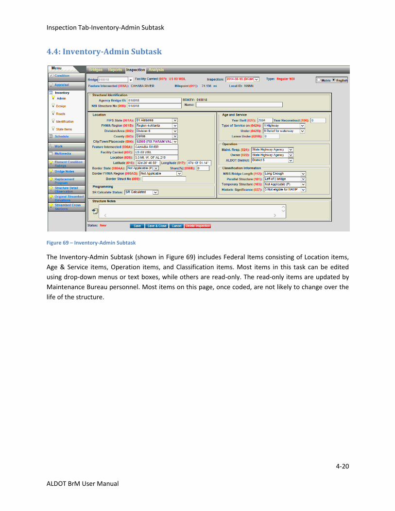
4.4: Inventory-Admin Subtask
Figure 69 – Inventory-Admin Subtask
The Inventory-Admin Subtask (shown in Figure 69) includes Federal Items consisting of Location items,
Age & Service items, Operation items, and Classification items. Most items in this task can be edited
using drop-down menus or text boxes, while others are read-only. The read-only items are updated by
Maintenance Bureau personnel. Most items on this page, once coded, are not likely to change over the
life of the structure.
Inspection Tab-Inventory-Design Subtask
4-21
ALDOT BrM User Manual
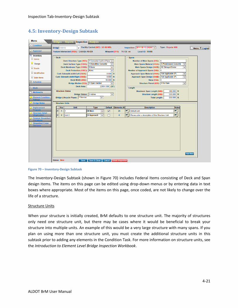
4.5: Inventory-Design Subtask
Figure 70 – Inventory-Design Subtask
The Inventory-Design Subtask (shown in Figure 70) includes Federal Items consisting of Deck and Span
design items. The items on this page can be edited using drop-down menus or by entering data in text
boxes where appropriate. Most of the items on this page, once coded, are not likely to change over the
life of a structure.
Structure Units
When your structure is initially created, BrM defaults to one structure unit. The majority of structures
only need one structure unit, but there may be cases where it would be beneficial to break your
structure into multiple units. An example of this would be a very large structure with many spans. If you
plan on using more than one structure unit, you must create the additional structure units in this
subtask prior to adding any elements in the Condition Task. For more information on structure units, see
the Introduction to Element Level Bridge Inspection Workbook.
Inspection Tab-Inventory-Roads Subtask
4-22
ALDOT BrM User Manual
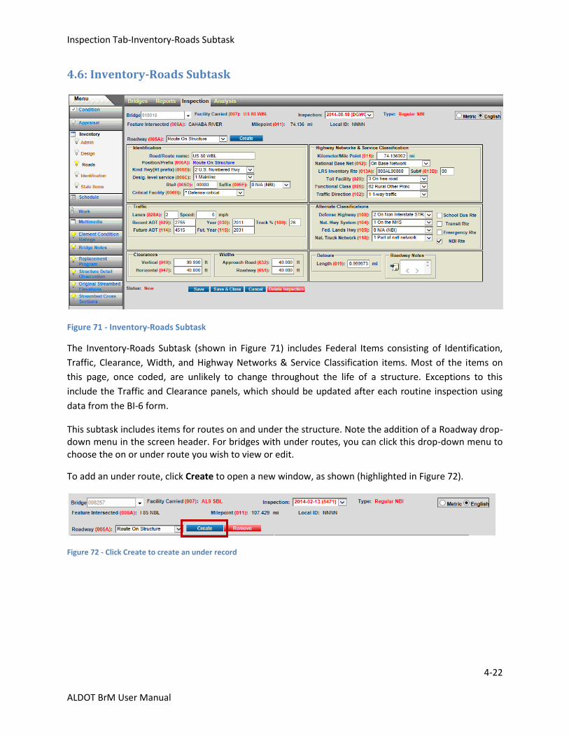
4.6: Inventory-Roads Subtask
Figure 71 - Inventory-Roads Subtask
The Inventory-Roads Subtask (shown in Figure 71) includes Federal Items consisting of Identification,
Traffic, Clearance, Width, and Highway Networks & Service Classification items. Most of the items on
this page, once coded, are unlikely to change throughout the life of a structure. Exceptions to this
include the Traffic and Clearance panels, which should be updated after each routine inspection using
data from the BI-6 form.
This subtask includes items for routes on and under the structure. Note the addition of a Roadway drop-down menu in the screen header. For bridges with under routes, you can click this drop-down menu to choose the on or under route you wish to view or edit.
To add an under route, click Create to open a new window, as shown (highlighted in Figure 72).
Figure 72 - Click Create to create an under record
Inspection Tab-Inventory-Roads Subtask
4-23
ALDOT BrM User Manual
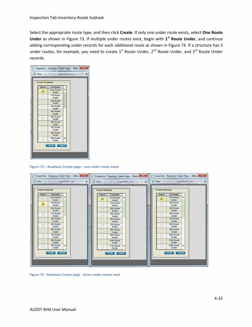
Select the appropriate route type, and then click Create. If only one under route exists, select One Route
Under as shown in Figure 73. If multiple under routes exist, begin with 1st Route Under, and continue
adding corresponding under records for each additional route as shown in Figure 74. If a structure has 3
under routes, for example, you need to create 1st Route Under, 2nd Route Under, and 3rd Route Under
records.
Figure 73 – Roadway Create page – one under route exists
Figure 74 - Roadway Create page - three under routes exist
Inspection Tab-Inventory-Roads Subtask
4-24
ALDOT BrM User Manual
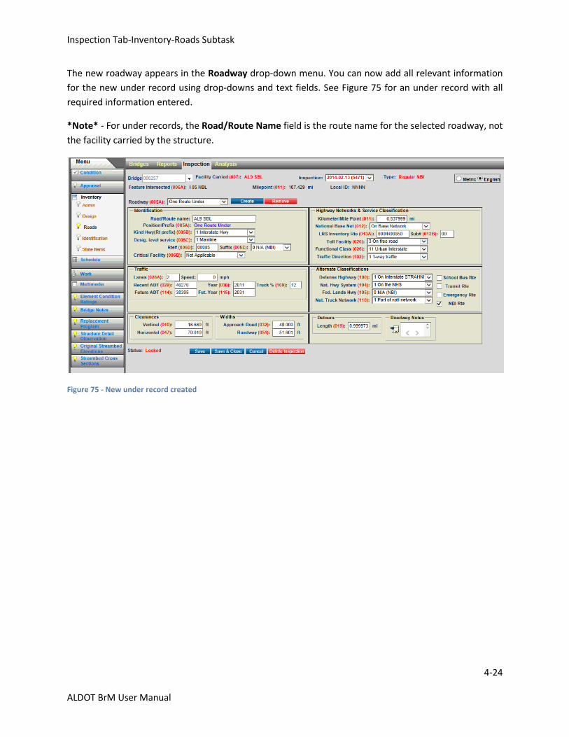
The new roadway appears in the Roadway drop-down menu. You can now add all relevant information
for the new under record using drop-downs and text fields. See Figure 75 for an under record with all
required information entered.
*Note* - For under records, the Road/Route Name field is the route name for the selected roadway, not
the facility carried by the structure.
Figure 75 - New under record created
Inspection Tab-Inventory-Identification Subtask
4-25
ALDOT BrM User Manual
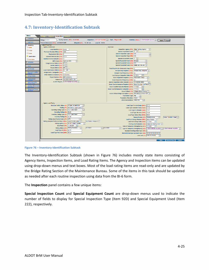
4.7: Inventory-Identification Subtask
Figure 76 – Inventory-Identification Subtask
The Inventory-Identification Subtask (shown in Figure 76) includes mostly state items consisting of
Agency Items, Inspection Items, and Load Rating Items. The Agency and Inspection items can be updated
using drop-down menus and text boxes. Most of the load rating items are read-only and are updated by
the Bridge Rating Section of the Maintenance Bureau. Some of the items in this task should be updated
as needed after each routine inspection using data from the BI-6 form.
The Inspection panel contains a few unique items:
Special Inspection Count and Special Equipment Count are drop-down menus used to indicate the
number of fields to display for Special Inspection Type (Item 92D) and Special Equipment Used (Item
222), respectively.
Inspection Tab-Inventory-Identification Subtask
4-26
ALDOT BrM User Manual
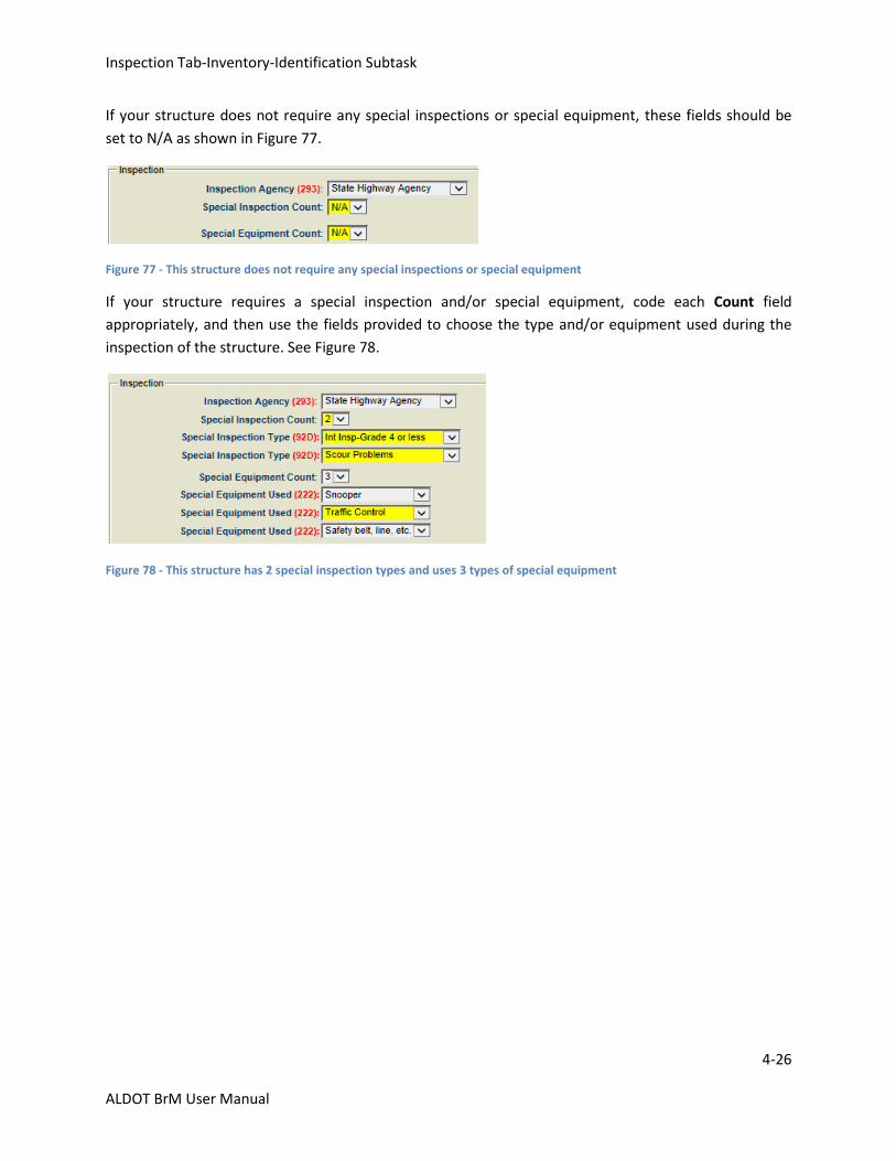
If your structure does not require any special inspections or special equipment, these fields should be
set to N/A as shown in Figure 77.
Figure 77 - This structure does not require any special inspections or special equipment
If your structure requires a special inspection and/or special equipment, code each Count field
appropriately, and then use the fields provided to choose the type and/or equipment used during the
inspection of the structure. See Figure 78.
Figure 78 - This structure has 2 special inspection types and uses 3 types of special equipment
Inspection Tab-Inventory-State Items Subtask
4-27
ALDOT BrM User Manual
4.8: Inventory-State Items Subtask
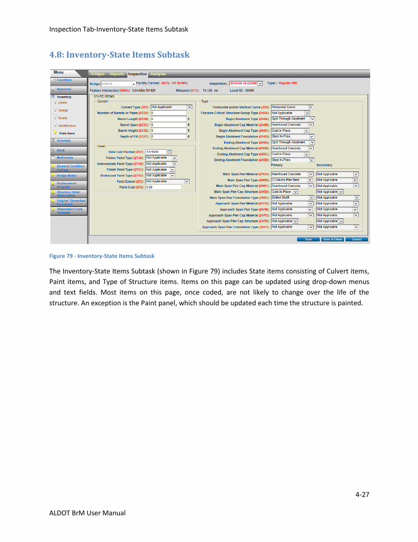
Figure 79 - Inventory-State Items Subtask
The Inventory-State Items Subtask (shown in Figure 79) includes State items consisting of Culvert items,
Paint items, and Type of Structure items. Items on this page can be updated using drop-down menus
and text fields. Most items on this page, once coded, are not likely to change over the life of the
structure. An exception is the Paint panel, which should be updated each time the structure is painted.
Inspection Tab-Schedule Task
4-28
ALDOT BrM User Manual
4.9: Schedule Task
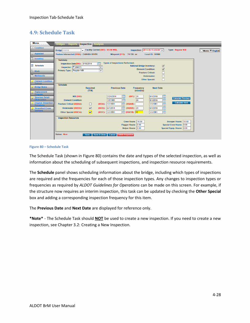
Figure 80 – Schedule Task
The Schedule Task (shown in Figure 80) contains the date and types of the selected inspection, as well as
information about the scheduling of subsequent inspections, and inspection resource requirements.
The Schedule panel shows scheduling information about the bridge, including which types of inspections
are required and the frequencies for each of those inspection types. Any changes to inspection types or
frequencies as required by ALDOT Guidelines for Operations can be made on this screen. For example, if
the structure now requires an interim inspection, this task can be updated by checking the Other Special
box and adding a corresponding inspection frequency for this item.
The Previous Date and Next Date are displayed for reference only.
*Note* - The Schedule Task should NOT be used to create a new inspection. If you need to create a new
inspection, see Chapter 3.2: Creating a New Inspection.
Inspection Tab-Work-Work Candidates Subtask
4-29
ALDOT BrM User Manual
4.10: Work-Work Candidates Subtask
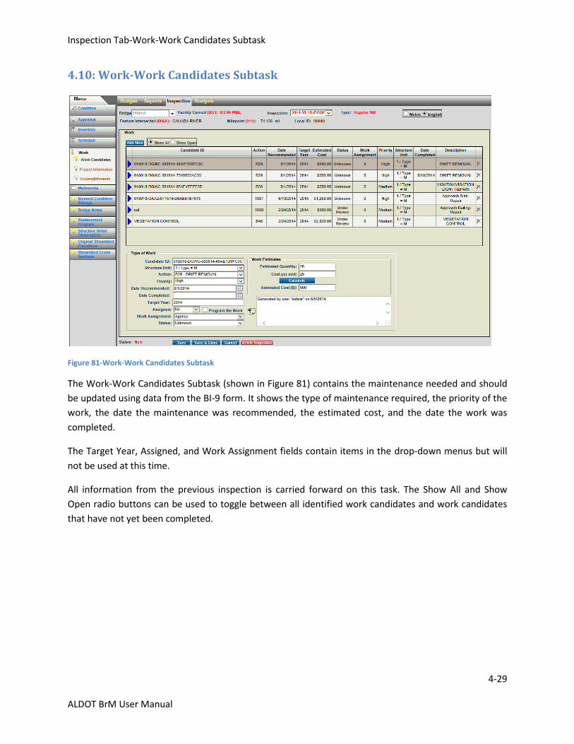
Figure 81-Work-Work Candidates Subtask
The Work-Work Candidates Subtask (shown in Figure 81) contains the maintenance needed and should
be updated using data from the BI-9 form. It shows the type of maintenance required, the priority of the
work, the date the maintenance was recommended, the estimated cost, and the date the work was
completed.
The Target Year, Assigned, and Work Assignment fields contain items in the drop-down menus but will
not be used at this time.
All information from the previous inspection is carried forward on this task. The Show All and Show
Open radio buttons can be used to toggle between all identified work candidates and work candidates
that have not yet been completed.
Inspection Tab-Work-Work Candidates Subtask
4-30
ALDOT BrM User Manual
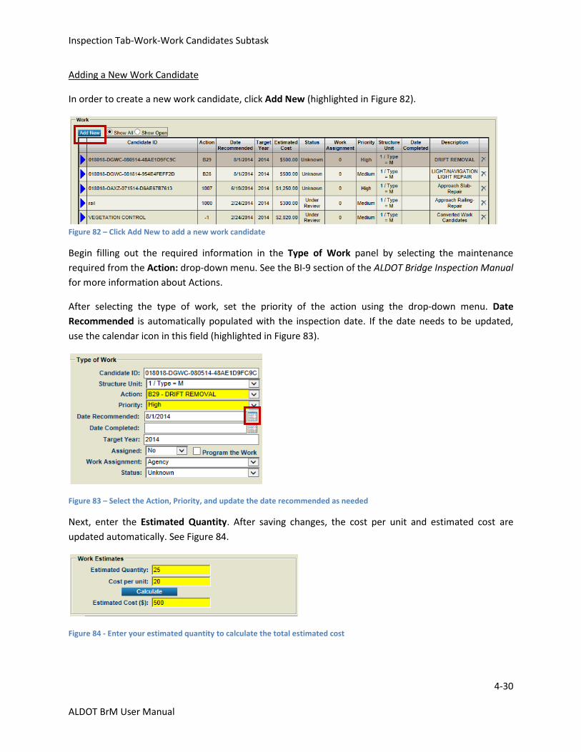
Adding a New Work Candidate
In order to create a new work candidate, click Add New (highlighted in Figure 82).
Figure 82 – Click Add New to add a new work candidate
Begin filling out the required information in the Type of Work panel by selecting the maintenance
required from the Action: drop-down menu. See the BI-9 section of the ALDOT Bridge Inspection Manual
for more information about Actions.
After selecting the type of work, set the priority of the action using the drop-down menu. Date
Recommended is automatically populated with the inspection date. If the date needs to be updated,
use the calendar icon in this field (highlighted in Figure 83).
Figure 83 – Select the Action, Priority, and update the date recommended as needed
Next, enter the Estimated Quantity. After saving changes, the cost per unit and estimated cost are
updated automatically. See Figure 84.
Figure 84 - Enter your estimated quantity to calculate the total estimated cost
Inspection Tab-Work-Work Candidates Subtask
4-31
ALDOT BrM User Manual
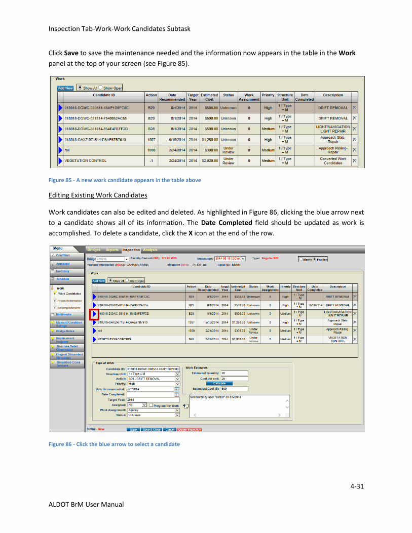
Click Save to save the maintenance needed and the information now appears in the table in the Work
panel at the top of your screen (see Figure 85).
Figure 85 - A new work candidate appears in the table above
Editing Existing Work Candidates
Work candidates can also be edited and deleted. As highlighted in Figure 86, clicking the blue arrow next
to a candidate shows all of its information. The Date Completed field should be updated as work is
accomplished. To delete a candidate, click the X icon at the end of the row.
Figure 86 - Click the blue arrow to select a candidate
Inspection Tab-Work-Project Information Subtask
4-32
ALDOT BrM User Manual
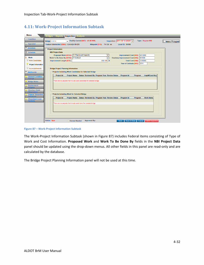
4.11: Work-Project Information Subtask
Figure 87 – Work-Project Information Subtask
The Work-Project Information Subtask (shown in Figure 87) includes Federal items consisting of Type of
Work and Cost Information. Proposed Work and Work To Be Done By fields in the NBI Project Data
panel should be updated using the drop-down menus. All other fields in this panel are read-only and are
calculated by the database.
The Bridge Project Planning Information panel will not be used at this time.
Inspection Tab-Work-Accomplishments Subtask
4-33
ALDOT BrM User Manual
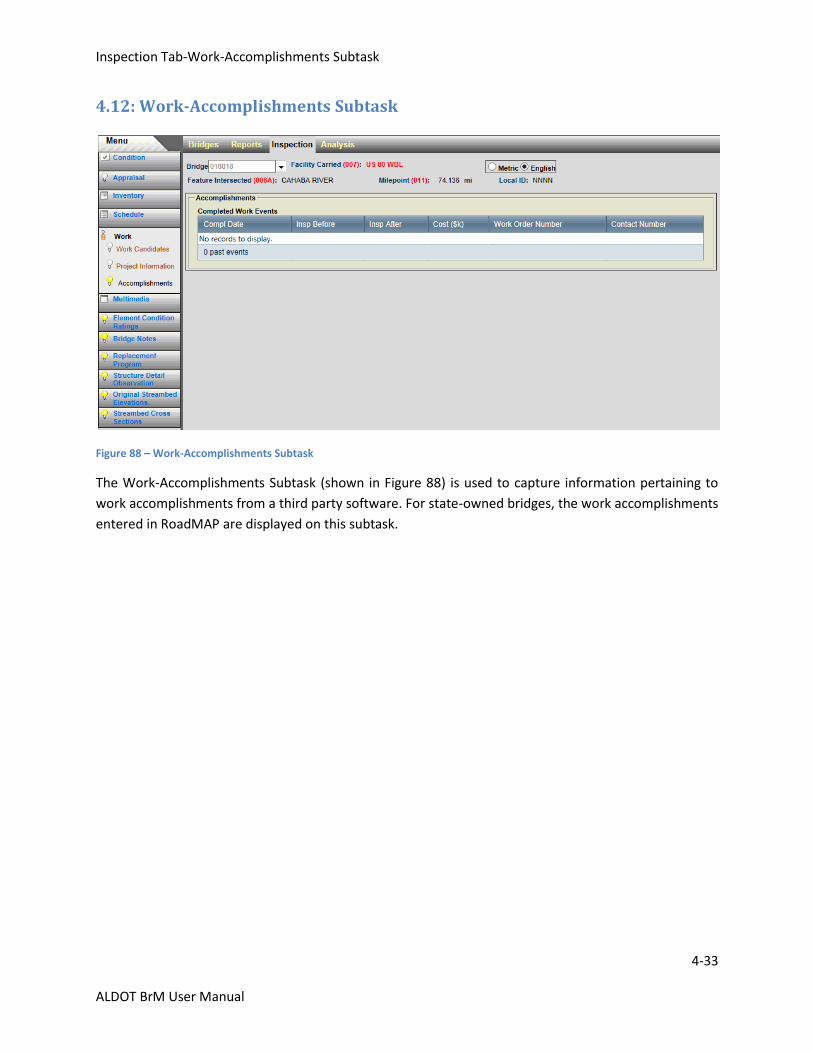
4.12: Work-Accomplishments Subtask
Figure 88 – Work-Accomplishments Subtask
The Work-Accomplishments Subtask (shown in Figure 88) is used to capture information pertaining to
work accomplishments from a third party software. For state-owned bridges, the work accomplishments
entered in RoadMAP are displayed on this subtask.
Inspection Tab-Multimedia Task
4-34
ALDOT BrM User Manual
4.13: Multimedia Task
Figure 89 – Multimedia Task
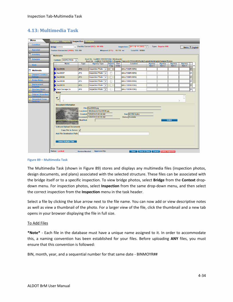
The Multimedia Task (shown in Figure 89) stores and displays any multimedia files (inspection photos,
design documents, and plans) associated with the selected structure. These files can be associated with
the bridge itself or to a specific inspection. To view bridge photos, select Bridge from the Context drop-
down menu. For inspection photos, select Inspection from the same drop-down menu, and then select
the correct inspection from the Inspection menu in the task header.
Select a file by clicking the blue arrow next to the file name. You can now add or view descriptive notes
as well as view a thumbnail of the photo. For a larger view of the file, click the thumbnail and a new tab
opens in your browser displaying the file in full size.
To Add Files
*Note* - Each file in the database must have a unique name assigned to it. In order to accommodate
this, a naming convention has been established for your files. Before uploading ANY files, you must
ensure that this convention is followed:
BIN, month, year, and a sequential number for that same date - BINMOYR##
Inspection Tab-Multimedia Task
4-35
ALDOT BrM User Manual
For example, BIN 9005 was inspected on May 15, 2013.
The first picture would be named 900505131, and the second would be named 900505132, etc.
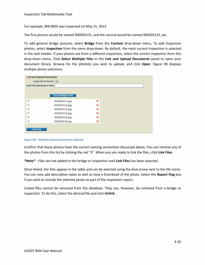
To add general bridge pictures, select Bridge from the Context drop-down menu. To add inspection
photos, select Inspection from the same drop-down. By default, the most current inspection is selected
in the task header. If your photos are from a different inspection, select the correct inspection from this
drop-down menu. Click Select Multiple Files in the Link and Upload Documents panel to open your
document library. Browse for the photo(s) you wish to upload, and click Open. Figure 90 displays
multiple photo selections.
Figure 90 – Multiple photos have been selected
Confirm that these photos have the correct naming convention discussed above. You can remove any of
the photos from this list by clicking the red “X”. When you are ready to link the files, click Link Files.
*Note* - Files are not added to the bridge or inspection until Link Files has been selected.
Once linked, the files appear in the table and can be selected using the blue arrow next to the file name.
You can now add descriptive notes as well as view a thumbnail of the photo. Select the Report Flag box
if you wish to include the selected photo as part of the inspection report.
Linked files cannot be removed from the database. They can, however, be unlinked from a bridge or
inspection. To do this, select the desired file and click Unlink.
Inspection Tab-Element Condition Ratings Task
4-36
ALDOT BrM User Manual
4.14: Element Condition Ratings Task
Figure 91 – Element Condition Ratings Task
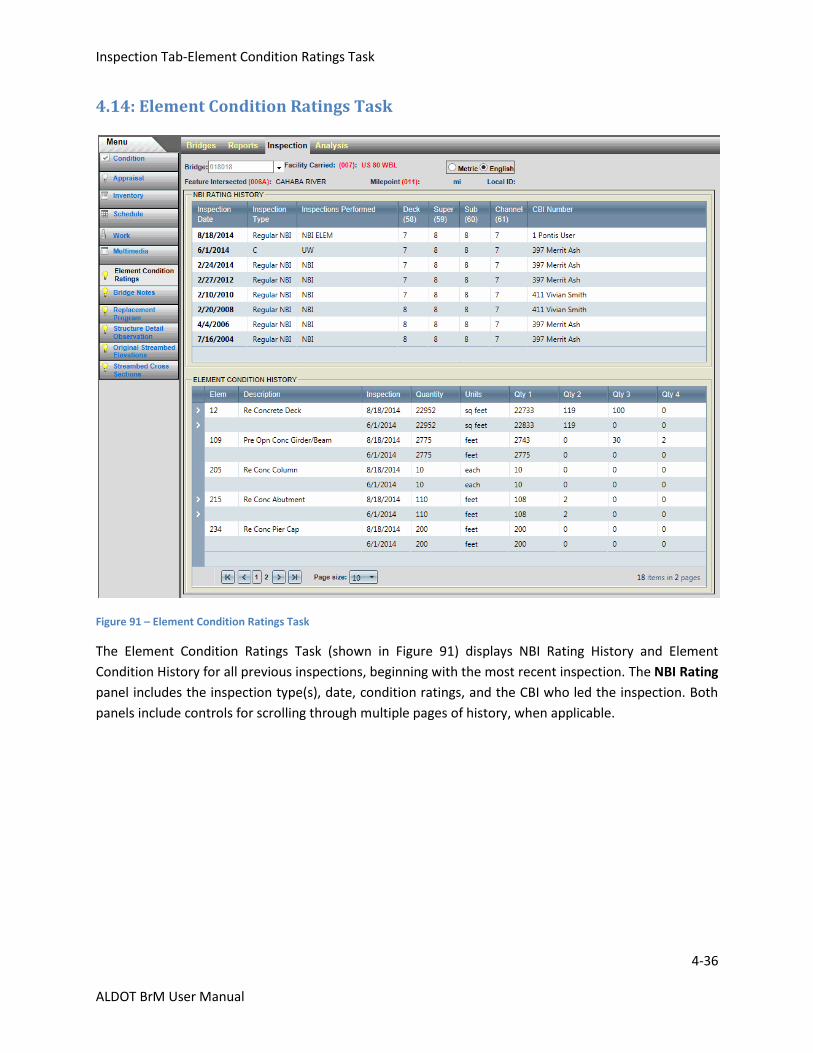
The Element Condition Ratings Task (shown in Figure 91) displays NBI Rating History and Element
Condition History for all previous inspections, beginning with the most recent inspection. The NBI Rating
panel includes the inspection type(s), date, condition ratings, and the CBI who led the inspection. Both
panels include controls for scrolling through multiple pages of history, when applicable.
Inspection Tab-Bridge Notes Task
4-37
ALDOT BrM User Manual
4.15: Bridge Notes Task
Figure 92 – Bridge Notes Task
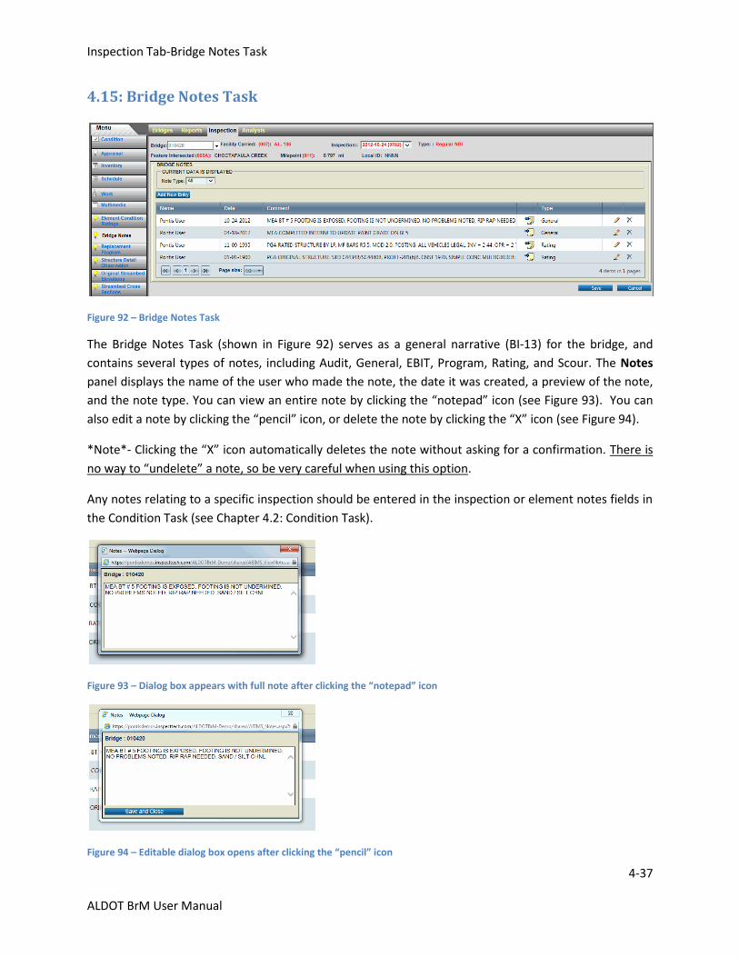
The Bridge Notes Task (shown in Figure 92) serves as a general narrative (BI-13) for the bridge, and
contains several types of notes, including Audit, General, EBIT, Program, Rating, and Scour. The Notes
panel displays the name of the user who made the note, the date it was created, a preview of the note,
and the note type. You can view an entire note by clicking the “notepad” icon (see Figure 93). You can
also edit a note by clicking the “pencil” icon, or delete the note by clicking the “X” icon (see Figure 94).
*Note*- Clicking the “X” icon automatically deletes the note without asking for a confirmation. There is
no way to “undelete” a note, so be very careful when using this option.
Any notes relating to a specific inspection should be entered in the inspection or element notes fields in
the Condition Task (see Chapter 4.2: Condition Task).
Figure 93 – Dialog box appears with full note after clicking the “notepad” icon
Figure 94 – Editable dialog box opens after clicking the “pencil” icon

Inspection Tab-Bridge Notes Task
4-38
ALDOT BrM User Manual
To Add a New Note
Figure 95 - Click Add Entry to add a new bridge note
Click Add New Entry (highlighted in Figure 95) to add a new bridge note. A new panel appears (see
Figure 96). Select your Note Type, and enter your note into the space provided. This field limited to
1000 characters. Click Save New Entry, and your note will appear in the notes list below (see Figure 97).
Figure 96 – Add New Entry panel; select a note type, enter comment in the space provided, and click Save New Entry
Figure 97 – New note displays in the notes table
Inspection Tab-Replacement Program Task
4-39
ALDOT BrM User Manual
4.16: Replacement Program Task
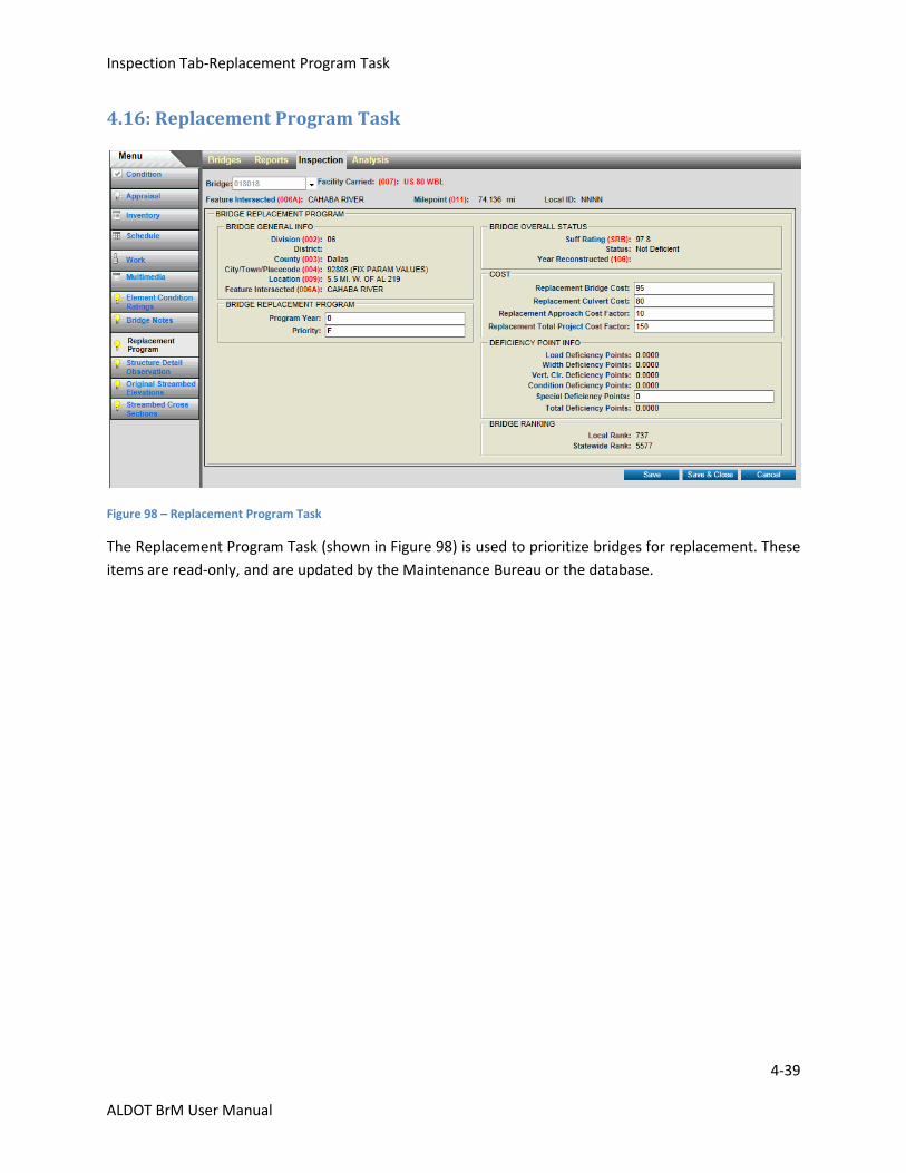
Figure 98 – Replacement Program Task
The Replacement Program Task (shown in Figure 98) is used to prioritize bridges for replacement. These
items are read-only, and are updated by the Maintenance Bureau or the database.
Inspection Tab-Structure Detail Observation Task
4-40
ALDOT BrM User Manual
4.17: Structure Detail Observation Task
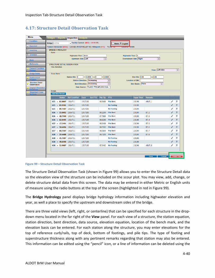
Figure 99 – Structure Detail Observation Task
The Structure Detail Observation Task (shown in Figure 99) allows you to enter the Structure Detail data
so the elevation view of the structure can be included on the scour plot. You may view, add, change, or
delete structure detail data from this screen. The data may be entered in either Metric or English units
of measure using the radio buttons at the top of the screen (highlighted in red in Figure 99).
The Bridge Hydrology panel displays bridge hydrology information including highwater elevation and
year, as well a place to specify the upstream and downstream sides of the bridge.
There are three valid views (left, right, or centerline) that can be specified for each structure in the drop-
down menu located in the far right of the View panel. For each view of a structure, the station equation,
station direction, bent direction, data source, elevation equation, location of the bench mark, and the
elevation basis can be entered. For each station along the structure, you may enter elevations for the
top of reference curb/rails, top of deck, bottom of footings, and pile tips. The type of footing and
superstructure thickness along with any pertinent remarks regarding that station may also be entered.
This information can be edited using the “pencil” icon, or a line of information can be deleted using the
Inspection Tab-Structure Detail Observation Task
4-41
ALDOT BrM User Manual
“X” icon on that row. You can delete entire views by clicking Delete View (highlighted in green in Figure
99) in the bottom right corner of the screen.
*Note*- Clicking Delete View automatically deletes the entire view without asking for a confirmation.
There is no way to “undelete” a view, so be very careful when using this option.
The following is a list of all fields on this screen and what should be entered in each one. A brief
explanation of each is included.
Bridge Hydrology
Highwater Elevation:
This field shows the highest water elevation during the maximum known flood event at the bridge site.
Highwater Year:
This 4-digit field shows the year of the maximum known flood event at the bridge site.
Upstream Side:
This field specifies the upstream side of the structure. It is referenced in the inventory route direction.
The field contains the parameters listed below:
Unknown – the upstream side is not known
Left – the upstream side is the left side of the bridge
Right - the upstream side is the right side of the bridge
Downstream Side:
This field specifies the downstream side of the structure. It is referenced in the inventory route
direction. The field contains the parameters listed below:
Unknown – the downstream side is not known
Left – the downstream side is the left side of the bridge
Right - the downstream side is the right side of the bridge
View Selection
View:
This field (located in the far right of the panel) is used to identify the view of the structure detail
information. The view of the bridge would be determined when traveling in the direction of the
inventory route (increasing mile markers). The field contains the parameters below:
Left view - data is for the left side of the bridge
Right view - data is for the right side of the bridge
Centerline view - data is for the centerline of the bridge
Most structure details will be entered using a centerline view unless the structure is superelevated or
skewed.
Inspection Tab-Structure Detail Observation Task
4-42
ALDOT BrM User Manual
Scour Items
Station EQ:
This field is used to capture a station equation which may be required to reference all horizontal
information from a common reference point. If the beginning of the bridge was assumed to be at station
1 + 00.00 and plans were later discovered showing the beginning of the bridge at station 5 + 42.68, then
a station equation could be used to correct the assumed station. This allows for the historical reference
material (i.e. plans and pile driving records) to be referenced appropriately to the bridge plot. It is
important to be aware that the station equation may be required for each section of data such as
structure details, original streambed elevations, and streambed cross sections, so that they are all
correlated by a common reference point. The station equations should be completed as required for the
bridge to plot correctly.
Station Direction:
This field is used to capture the station direction determined when traveling in the direction of the
inventory route (increasing mile markers). The field contains the parameters below:
Increasing
Decreasing
Bent Direction:
This field is used to capture the bent direction determined when traveling in the direction of the
inventory route (increasing mile markers). The field contains the parameters below:
Increasing
Decreasing
The bent direction should always be increasing.
Data Source:
This field captures the source of the structure detail information. The structure elevations may come
from "design" plans, "as-built" plans, or a field survey.

Inspection Tab-Structure Detail Observation Task
4-43
ALDOT BrM User Manual
Elev EQ:
This field captures the elevation equation which may be used to reference all vertical information from a
common reference plane for plotting. If the bridge details are initially plotted based on an assumed
reference elevation and later plans are located which show the actual elevations, the initial assumed
reference elevation can be equated to the actual elevation based on the information from the plans.
For example, a crew goes to the field to gather bridge detail information and they set a reference point
with assumed elevations, such as 150.00 feet. Later, a different crew goes to gather streambed sounding
information and they use the same reference point but assume an elevation of 100.00 feet. These plots
can and must be put on a common reference line by keying an elevation equation. In this case, the
elevation equation on the streambed soundings form would be 100.00 feet equals 150.00 feet because
the streambed soundings should be linked to the same elevation.
Be aware that an elevation equation may be required for each section of data such as structure details,
original streambed elevations, and streambed cross sections, so that they are all correlated by a
common reference point. The elevation equations should be completed as required for the bridge
information to plot correctly.
Location of Benchmark (BM):
This field captures the location of the bench mark used for referencing the cross sections (ex. top of rail,
from curb, from deck).
Elevation Basis:
This field captures the type of platform the elevations for the structure details are based on. The field
contains the parameters below:
Code: Description:
Assumption Elevations are based on assumption. From some semi-permanent, fixed
point, on or near the bridge, an elevation is assumed. All subsequent
elevations for the structure are based on this "assumed" elevation.
US Geodetic Survey Elevations are based on a U.S. Geodetic Survey bench mark or an
Alabama Department of Transportation bench mark. This would be
basically the same as elevations from the bridge plans except that plans
might not be available on the structure, but a geodetic marker is
conveniently close.
Plans Elevations are taken from the bridge plans. In this case, the elevations
are usually based on a permanent U.S. Geodetic Survey bench mark or
an Alabama Department of Transportation bench mark, as referenced in
the bridge plans.
Inspection Tab-Structure Detail Observation Task
4-44
ALDOT BrM User Manual
Details
Station:
This field captures the stations along the structure. Each station should be located at some changed
condition (i.e. deck elevation change, substructure support location, the edge of water, the edge of a
stream bank). The maximum value which can be entered into this field is 9999 + 99.999. Negative
stations can be entered if needed.
Ref Curb/Rail: This field captures the elevation for the top of the reference point whether it is the curb, rail, or some other feature. A negative sign may be entered, if necessary. Note that the reference point is not plotted, but used to subtract sounding depths to obtain actual channel cross section elevations.
Deck:
This field captures the elevation for the top of deck of the structure. A negative sign may be entered, if
necessary.
Bot FTG:
This field captures the elevation for the bottom of a spread, rock, or pile footing, if present. If there are
two footings in a bent, such as for a two column bent, the shallowest footing elevation should be
entered. This field is seven digits long including three decimal places. A negative sign may be entered, if
necessary. If the elevation of the bottom is unknown, leave it blank.
Pile Tip:
This field captures the pile tip elevation of the shallowest pile in a bent or under a pile footing, when
present, and is seven digits long including three decimal places. A negative sign may be entered, if
necessary. If the elevation is unknown, leave it blank.
FTG:
This field captures the type of footing. The data is used to graphically represent that particular type of
footing on the scour plot. The field contains the parameters below:
Code: Description:
No Footing No footing at this station, however, some other change occurs
such as a change in the deck elevation or the superstructure
thickness. No elevation should be entered for the bottom of
footing or pile tip categories.
Pile Footing Spread footing on piles. If this code is entered but a bottom of
footing elevation or pile tip elevation is not, it is assumed that
these elevations are unknown and the plot of the structure
reflects this. If elevations are known, they should be entered in
the Bot FTG and Pile Tip fields.
Inspection Tab-Structure Detail Observation Task
4-45
ALDOT BrM User Manual
Spread Footing Spread footing with no piles. If this code is entered but a
bottom of footing elevation is not, it is assumed that the
elevation is unknown and the structure plot reflects this. If this
elevation is known, it should be entered in the Bot FTG field.
Pile Bent Pile bents not related to a spread footing. If this is coded but a
pile tip elevation is not, it is assumed that the elevation is
unknown and the structure plot reflects this. If this elevation is
known, it should be entered in the Pile Tip field.
Spread footing on Rock Spread footing on rock. If this code is entered but a footing
elevation is not, it is assumed that the elevation is unknown and
the structure plot reflects this. If this elevation is known, it
should be entered in the Bot FTG field.
Tower Bent Tower bent. If this code is entered but a pile tip elevation is not,
it is assumed that the elevation is unknown and the structure
plot reflects this. If this elevation is known, it should be entered
in the Pile Tip field.
Drilled Shaft Drilled shaft. If this is coded but a pile tip elevation is not, it is
assumed that the elevation is unknown and the structure plot
reflects this. If this elevation is known, it should be entered in
the Pile Tip field.
Super Thick:
This field captures the thickness of the superstructure to provide information for plotting the bottom of
the girders.
Remarks:
This narrative field captures any pertinent remarks about the structure at the particular station.
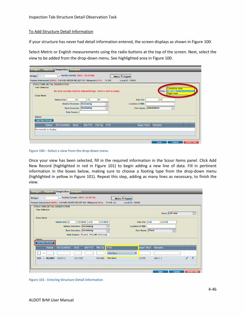
Inspection Tab-Structure Detail Observation Task
4-46
ALDOT BrM User Manual
To Add Structure Detail Information
If your structure has never had detail information entered, the screen displays as shown in Figure 100.
Select Metric or English measurements using the radio buttons at the top of the screen. Next, select the
view to be added from the drop-down menu. See highlighted area in Figure 100.
Figure 100 – Select a view from the drop-down menu
Once your view has been selected, fill in the required information in the Scour Items panel. Click Add New Record (highlighted in red in Figure 101) to begin adding a new line of data. Fill in pertinent information in the boxes below, making sure to choose a footing type from the drop-down menu (highlighted in yellow in Figure 101). Repeat this step, adding as many lines as necessary, to finish the view.
Figure 101 - Entering Structure Detail information
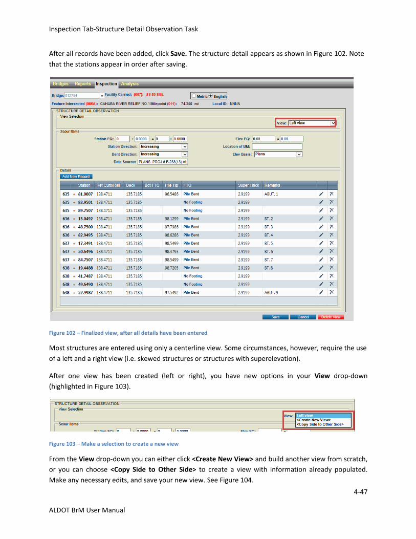
Inspection Tab-Structure Detail Observation Task
4-47
ALDOT BrM User Manual
After all records have been added, click Save. The structure detail appears as shown in Figure 102. Note
that the stations appear in order after saving.
Figure 102 – Finalized view, after all details have been entered
Most structures are entered using only a centerline view. Some circumstances, however, require the use
of a left and a right view (i.e. skewed structures or structures with superelevation).
After one view has been created (left or right), you have new options in your View drop-down
(highlighted in Figure 103).
Figure 103 – Make a selection to create a new view
From the View drop-down you can either click <Create New View> and build another view from scratch,
or you can choose <Copy Side to Other Side> to create a view with information already populated.
Make any necessary edits, and save your new view. See Figure 104.
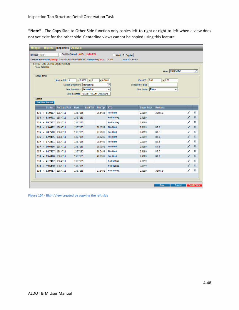
Inspection Tab-Structure Detail Observation Task
4-48
ALDOT BrM User Manual
*Note* - The Copy Side to Other Side function only copies left-to-right or right-to-left when a view does
not yet exist for the other side. Centerline views cannot be copied using this feature.
Figure 104 - Right View created by copying the left side
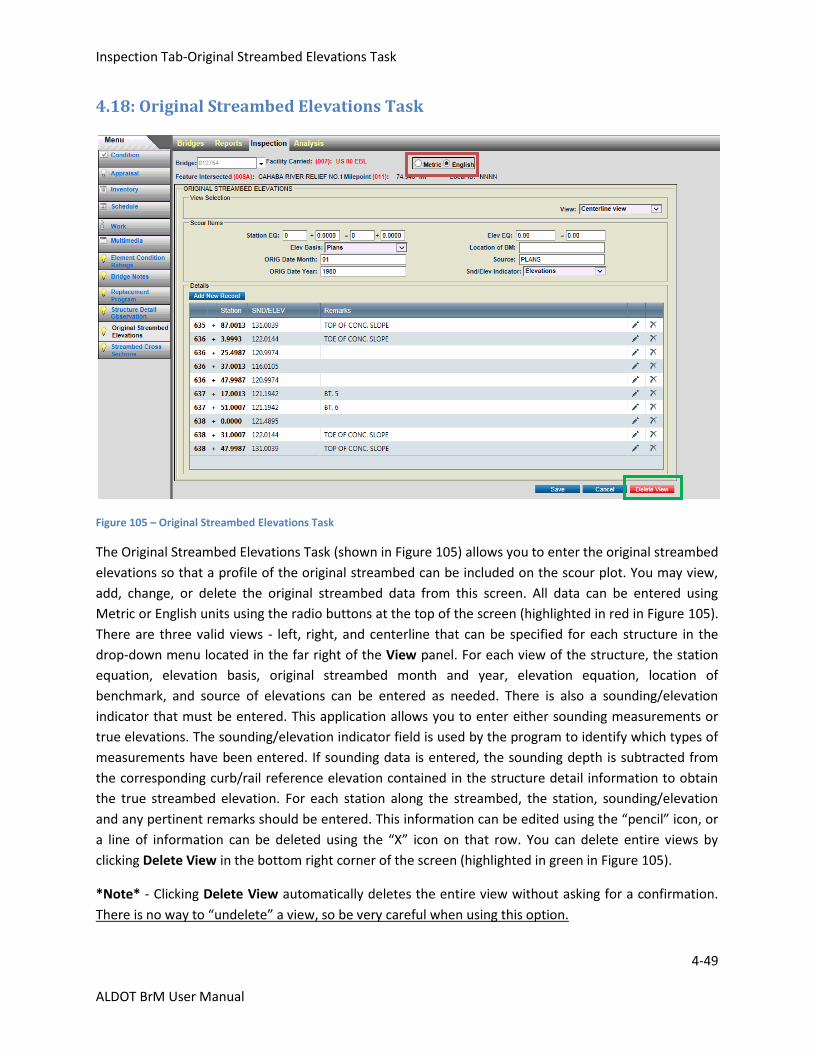
Inspection Tab-Original Streambed Elevations Task
4-49
ALDOT BrM User Manual
4.18: Original Streambed Elevations Task
Figure 105 – Original Streambed Elevations Task
The Original Streambed Elevations Task (shown in Figure 105) allows you to enter the original streambed
elevations so that a profile of the original streambed can be included on the scour plot. You may view,
add, change, or delete the original streambed data from this screen. All data can be entered using
Metric or English units using the radio buttons at the top of the screen (highlighted in red in Figure 105).
There are three valid views - left, right, and centerline that can be specified for each structure in the
drop-down menu located in the far right of the View panel. For each view of the structure, the station
equation, elevation basis, original streambed month and year, elevation equation, location of
benchmark, and source of elevations can be entered as needed. There is also a sounding/elevation
indicator that must be entered. This application allows you to enter either sounding measurements or
true elevations. The sounding/elevation indicator field is used by the program to identify which types of
measurements have been entered. If sounding data is entered, the sounding depth is subtracted from
the corresponding curb/rail reference elevation contained in the structure detail information to obtain
the true streambed elevation. For each station along the streambed, the station, sounding/elevation
and any pertinent remarks should be entered. This information can be edited using the “pencil” icon, or
a line of information can be deleted using the “X” icon on that row. You can delete entire views by
clicking Delete View in the bottom right corner of the screen (highlighted in green in Figure 105).
*Note* - Clicking Delete View automatically deletes the entire view without asking for a confirmation.
There is no way to “undelete” a view, so be very careful when using this option.
Inspection Tab-Original Streambed Elevations Task
4-50
ALDOT BrM User Manual
The following is a list of the valid fields on the screen. A brief explanation of each is included.
View Selection
View:
This field is used to identify the view of the original streambed elevations. The view of the bridge would
be determined when traveling in the direction of the inventory route (increasing mile markers). The field
contains the parameters below:
Left view - data is for the left side of the bridge
Right view - data is for the right side of the bridge
Centerline view - data is for the centerline of the bridge
Scour Items
Station EQ:
This field is used to capture a station equation which may be required to reference all horizontal
information from a common reference point. If the beginning of the bridge was assumed to be at station
1 + 00.00 and plans were later discovered showing 5 + 42.68, then a station equation could be used to
correct the assumed station so historical reference material (i.e. plans and pile driving records) could be
referenced appropriately to the bridge plot. Be aware that the station equation may be required for
each section of data such as structure details, original streambed elevations, and streambed cross
sections, so that they are all correlated by a common reference point. The station equations should be
completed as required for the bridge to plot correctly.
Elevation Basis:
This field captures the type of platform the elevations for the original streambed are based on. The field
contains the parameters below:
Code: Description:
Assumption Elevations are based on assumption. From some semi-permanent, fixed
point, on or near the bridge, an elevation is assumed. All subsequent
elevations for the structure are based on this "assumed" elevation.
US Geodetic Survey Elevations are based on a U.S. Geodetic Survey bench mark or an
Alabama Department of Transportation bench mark. This would be
basically the same as elevations from the bridge plans except that plans
might not be available on the structure, but a geodetic marker is
conveniently close.
Plans Elevations are taken from the bridge plans. In this case, the elevations
are usually based on a permanent U.S. Geodetic Survey bench mark or
an Alabama Department of Transportation bench mark, as referenced in
the bridge plans.
Inspection Tab-Original Streambed Elevations Task
4-51
ALDOT BrM User Manual
Orig Date Month:
This field captures the month of the original streambed elevation.
Orig Date Year:
This field captures the year of the original streambed elevation.
Elev EQ:
This field captures the elevation equation which may be used to reference all vertical information from a
common reference plane for plotting. If the bridge details are initially plotted based on an assumed
reference elevation and later plans are located which show the actual elevations, the initial assumed
reference elevation can be equated to the actual elevation based on the information from the plans.
For example, a crew goes to the field to gather bridge detail information and they set a reference point
with assumed elevations, such as 150.00 feet. Later, a different crew goes to gather streambed sounding
information and they use the same reference point but assume an elevation of 100.00 feet. These plots
can and must be put on a common reference line by keying an elevation equation. In this case, the
elevation equation on the streambed soundings form would be 100.00 feet equals 150.00 feet because
the streambed soundings should be linked to the same elevation.
Be aware that an elevation equation may be required for each section of data such as structure details,
original streambed elevations, and streambed cross sections, so that they are all correlated by a
common reference point. The elevation equations should be completed as required for the bridge
information to plot correctly.
Location of Benchmark (BM):
This field captures the location of the bench mark used for referencing the cross sections (ex. top of rail,
from curb, from deck).
Source:
This field captures the source of the original streambed elevations. This information may come from
plans or the first streambed soundings taken at a structure.
Sounding/Elevation Indicator (SND/ELEV Indicator):
This field is used to indicate whether the recordings are actual elevations or soundings. This indicator is
used by the program to determine the type of data that is being entered. The field contains the
parameters below:
Code: Description:
Elevations Elevation data give actual elevations of the points. This requires the
inspector to calculate the elevation based on measurements. For
example, if the measurements are taken with a rod and level, then the
elevation of each reading would be calculated by subtracting the rod
reading from the elevation of the level (height of the instrument).
Inspection Tab-Original Streambed Elevations Task
4-52
ALDOT BrM User Manual
Soundings Soundings data should be used if the data recorded are measurements
taken from the bridge deck railing or some other reference feature
using a weighted tape with no calculations made. This measurement is
automatically subtracted from the curb/rail reference elevations
recorded in the bridge detail information of the scour module. For more
information on the bridge detail portion of the scour module, refer to
the Structure Scour/Hydrology Module Users Guide.
Details
Station:
This field captures the particular station at which a streambed elevation change occurs. The maximum
value which can be entered into this field is 9999 + 99.999. Negative stations can be entered if needed.
Sounding/Elevation:
This field captures the sounding measurement or elevation for each station. Negative soundings may be
entered, if needed. A value is required for this field if a station has been entered.
Remarks:
This narrative field captures any pertinent remarks that are related to that station.
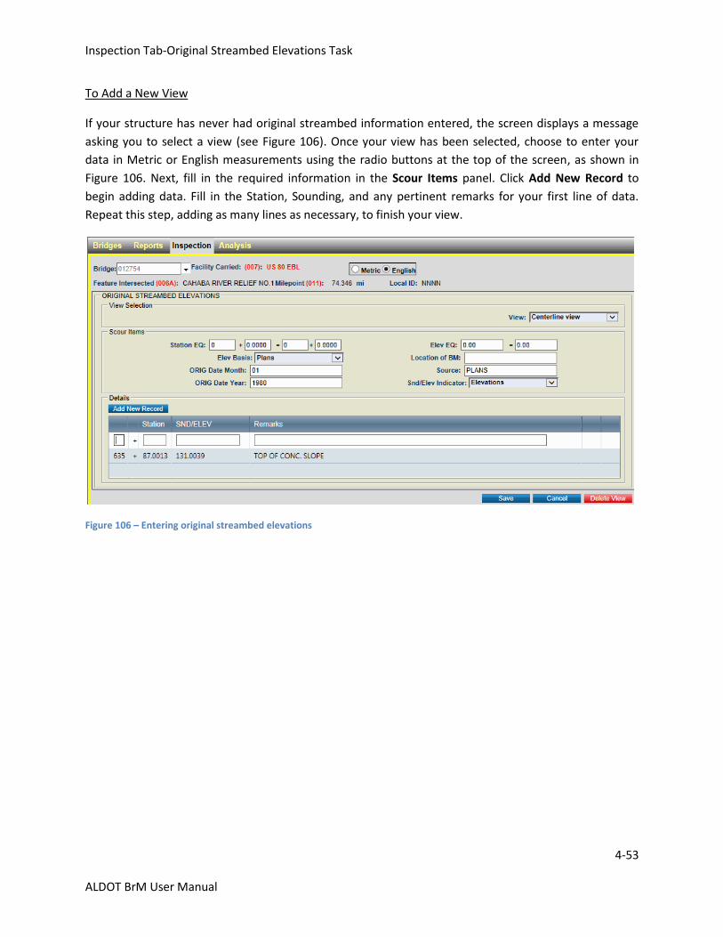
Inspection Tab-Original Streambed Elevations Task
4-53
ALDOT BrM User Manual
To Add a New View
If your structure has never had original streambed information entered, the screen displays a message
asking you to select a view (see Figure 106). Once your view has been selected, choose to enter your
data in Metric or English measurements using the radio buttons at the top of the screen, as shown in
Figure 106. Next, fill in the required information in the Scour Items panel. Click Add New Record to
begin adding data. Fill in the Station, Sounding, and any pertinent remarks for your first line of data.
Repeat this step, adding as many lines as necessary, to finish your view.
Figure 106 – Entering original streambed elevations
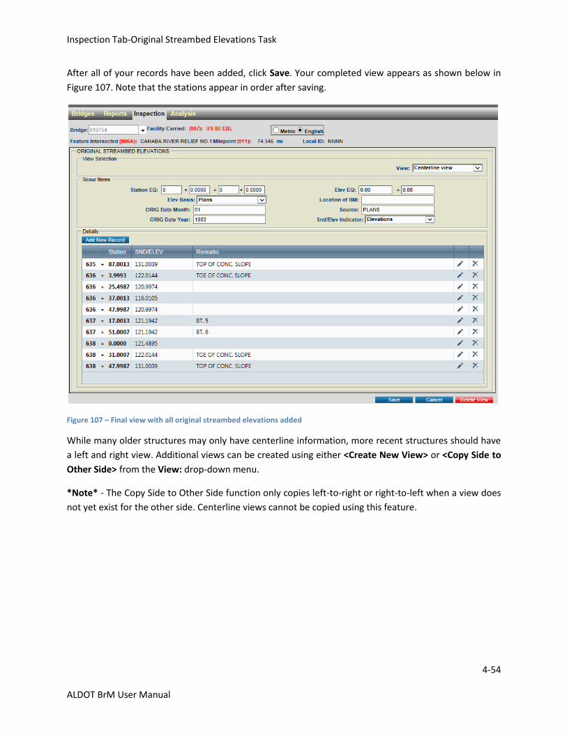
Inspection Tab-Original Streambed Elevations Task
4-54
ALDOT BrM User Manual
After all of your records have been added, click Save. Your completed view appears as shown below in
Figure 107. Note that the stations appear in order after saving.
Figure 107 – Final view with all original streambed elevations added
While many older structures may only have centerline information, more recent structures should have
a left and right view. Additional views can be created using either <Create New View> or <Copy Side to
Other Side> from the View: drop-down menu.
*Note* - The Copy Side to Other Side function only copies left-to-right or right-to-left when a view does
not yet exist for the other side. Centerline views cannot be copied using this feature.
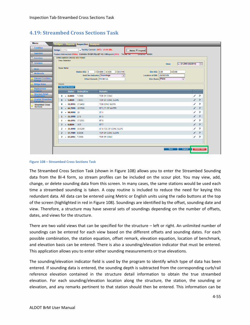
Inspection Tab-Streambed Cross Sections Task
4-55
ALDOT BrM User Manual
4.19: Streambed Cross Sections Task
Figure 108 – Streambed Cross Sections Task
The Streambed Cross Section Task (shown in Figure 108) allows you to enter the Streambed Sounding
data from the BI-4 form, so stream profiles can be included on the scour plot. You may view, add,
change, or delete sounding data from this screen. In many cases, the same stations would be used each
time a streambed sounding is taken. A copy routine is included to reduce the need for keying this
redundant data. All data can be entered using Metric or English units using the radio buttons at the top
of the screen (highlighted in red in Figure 108). Soundings are identified by the offset, sounding date and
view. Therefore, a structure may have several sets of soundings depending on the number of offsets,
dates, and views for the structure.
There are two valid views that can be specified for the structure – left or right. An unlimited number of
soundings can be entered for each view based on the different offsets and sounding dates. For each
possible combination, the station equation, offset remark, elevation equation, location of benchmark,
and elevation basis can be entered. There is also a sounding/elevation indicator that must be entered.
This application allows you to enter either sounding measurements or true elevations.
The sounding/elevation indicator field is used by the program to identify which type of data has been
entered. If sounding data is entered, the sounding depth is subtracted from the corresponding curb/rail
reference elevation contained in the structure detail information to obtain the true streambed
elevation. For each sounding/elevation location along the structure, the station, the sounding or
elevation, and any remarks pertinent to that station should then be entered. This information can be
Inspection Tab-Streambed Cross Sections Task
4-56
ALDOT BrM User Manual
edited using the “pencil” icon, or a line of information can be deleted using the “X” icon on that row.
You can delete entire views by clicking Delete View in the bottom right corner of the screen (highlighted
in green in Figure 108).
*Note* - Clicking Delete View automatically deletes the entire view without asking for a confirmation.
There is no way to “undelete” a view, so be very careful when using this option.
The following is a list of the valid fields on this screen. A brief explanation of each is included.
View Selection
View:
This field is used to identify the view in which the cross sections were taken. The view of the bridge
would be determined when traveling in the direction of the inventory route (increasing mile markers).
The field contains the parameters below:
Left view - data is for the left side of the bridge
Right view - data is for the right side of the bridge
Offset:
This field is used to indicate the distance of the offset from where the streambed soundings were taken.
The field is four characters long to record the offset distance to the nearest tenth of a meter or foot. For
example, if the readings are taken from the left edge of the bridge deck, then this item should be
recorded as one-half of the bridge deck width if the offset is from the centerline of the bridge.
Sounding Month:
This field captures the month the streambed soundings were taken.
Sounding Year:
This 4-digit field captures the year the streambed soundings were taken.
Scour Items
Station EQ:
This field is used to capture a station equation which may be required to reference all horizontal
information from a common reference point. If the beginning of the bridge was assumed to be at station
1 + 00.00 and plans were later discovered showing the beginning of the bridge at station 5 + 42.68, then
a station equation could be used to correct the assumed station. This allows historical reference
material (i.e. plans and pile driving records) to be referenced appropriately to the bridge plot. It is
important to note that the station equation may be required for each section of data such as structure
details, original streambed elevations, and streambed cross sections, so that they are all correlated by a
common reference point. The station equations should be completed as required for the bridge to plot
correctly.
Inspection Tab-Streambed Cross Sections Task
4-57
ALDOT BrM User Manual
Sounding/Elevation Indicator (SND/ELEV Indicator):
This field is used to indicate whether the recordings are actual elevations or soundings. This indicator is
used by the program to determine the type of data that is being entered. The field contains the
parameters below:
Code: Description:
Elevations Elevation data gives actual elevations of the points. This requires the
inspector to calculate the elevation based on measurements. For
example, if the measurements are taken with a rod and level, then the
elevation of each reading would be calculated by subtracting the rod
reading from the elevation of the level (height of the instrument).
Soundings Soundings data should be used if the data recorded are measurements
taken from the bridge deck railing or some other reference feature
using a weighted tape with no calculations made. This measurement is
automatically subtracted from the curb/rail reference elevations
recorded in the bridge detail information of the scour module. For more
information on the bridge detail portion of the scour module, refer to
the Structure Scour/Hydrology Module Users Guide.
Offset Remark:
This is a narrative field used to describe the offset location. This field is twenty characters in length. For
example, a typical offset remark would relate an offset distance from the centerline of the bridge.
Elev EQ:
This field captures the elevation equation which may be used to reference all vertical information from a
common reference plane for plotting. If the bridge details are initially plotted based on an assumed
reference elevation and later plans are located showing the actual elevations for the bridge, the initial
assumed reference elevation can be equated to what the actual elevation is at that point based on the
information from the plans.
If a crew goes to the field to gather bridge detail information and they set a reference point with
assumed elevations, such as 150.00 feet, then a different crew gathers streambed sounding information
and they use the same reference point but assume an elevation of 100.00 feet, these plots can and must
be put on a common reference line by keying an elevation equation. In this case, the elevation equation
on the streambed soundings form would be 100.00 feet equals 150.00 feet because the streambed
soundings should be linked to the same elevation.
Be aware that an elevation equation may be required for each section of data such as structure details,
original streambed elevations, and streambed cross sections, so that they are all correlated by a
common reference point. The elevation equations should be completed as required for the bridge
information to plot correctly.
Inspection Tab-Streambed Cross Sections Task
4-58
ALDOT BrM User Manual
Location of Benchmark (BM)
This field captures the location of the bench mark used for referencing the cross sections (ex. top of rail,
from curb, from deck).
Elevation Basis
This field captures the type of platform the elevations for the soundings are based on. The field contains
the parameters below:
Code: Description:
Assumption Elevations are based on assumption. From some semi-permanent, fixed
point, on or near the bridge, an elevation is assumed. All subsequent
elevations for the structure are based on this "assumed" elevation.
US Geodetic Survey Elevations are based on a U.S. Geodetic Survey bench mark or an
Alabama Department of Transportation bench mark. This would be
basically the same as elevations from the bridge plans except that plans
might not be available on the structure, but a geodetic marker is
conveniently close.
Plans Elevations are taken from the bridge plans. In this case, the elevations
are usually based on a permanent U.S. Geodetic Survey bench mark or
an Alabama Department of Transportation bench mark, as referenced in
the bridge plans.
Details
Station:
This field captures the particular station at which the sounding or elevation was taken. The maximum
value which can be entered into this field is 9999 + 99.999. Negative stations can be entered if needed.
Sounding/Elevation:
This field captures the sounding measurement or elevation for each station. Negative soundings may be
entered, if needed. A value is required for this field if a station has been entered.
Remarks:
This narrative field captures any pertinent remarks that are related to that station.
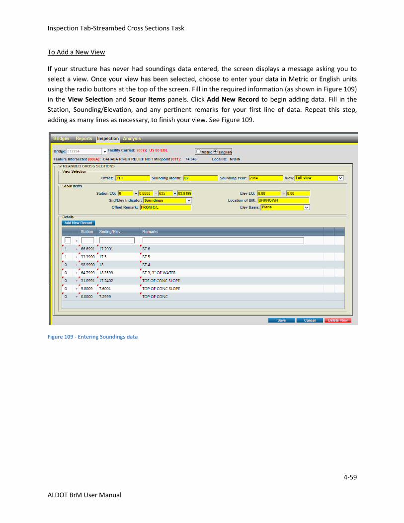
Inspection Tab-Streambed Cross Sections Task
4-59
ALDOT BrM User Manual
To Add a New View
If your structure has never had soundings data entered, the screen displays a message asking you to
select a view. Once your view has been selected, choose to enter your data in Metric or English units
using the radio buttons at the top of the screen. Fill in the required information (as shown in Figure 109)
in the View Selection and Scour Items panels. Click Add New Record to begin adding data. Fill in the
Station, Sounding/Elevation, and any pertinent remarks for your first line of data. Repeat this step,
adding as many lines as necessary, to finish your view. See Figure 109.
Figure 109 - Entering Soundings data
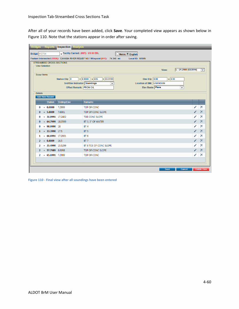
Inspection Tab-Streambed Cross Sections Task
4-60
ALDOT BrM User Manual
After all of your records have been added, click Save. Your completed view appears as shown below in
Figure 110. Note that the stations appear in order after saving.
Figure 110 - Final view after all soundings have been entered
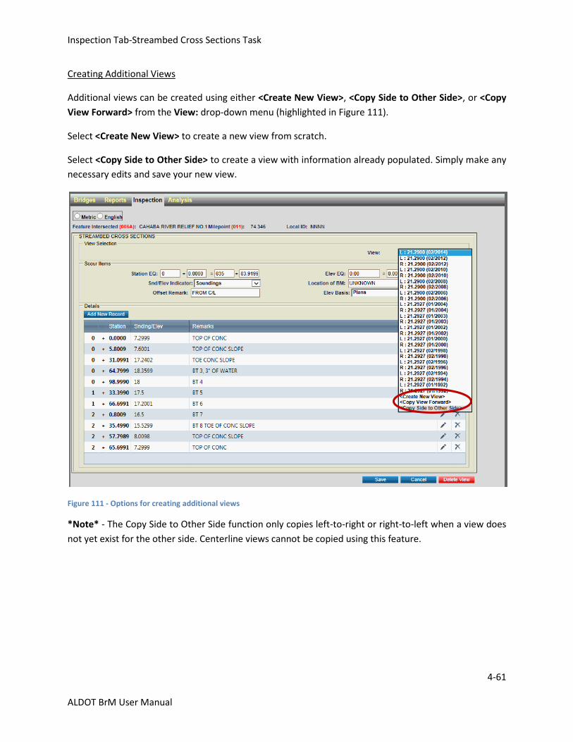
Inspection Tab-Streambed Cross Sections Task
4-61
ALDOT BrM User Manual
Creating Additional Views
Additional views can be created using either <Create New View>, <Copy Side to Other Side>, or <Copy
View Forward> from the View: drop-down menu (highlighted in Figure 111).
Select <Create New View> to create a new view from scratch.
Select <Copy Side to Other Side> to create a view with information already populated. Simply make any
necessary edits and save your new view.
Figure 111 - Options for creating additional views
*Note* - The Copy Side to Other Side function only copies left-to-right or right-to-left when a view does
not yet exist for the other side. Centerline views cannot be copied using this feature.
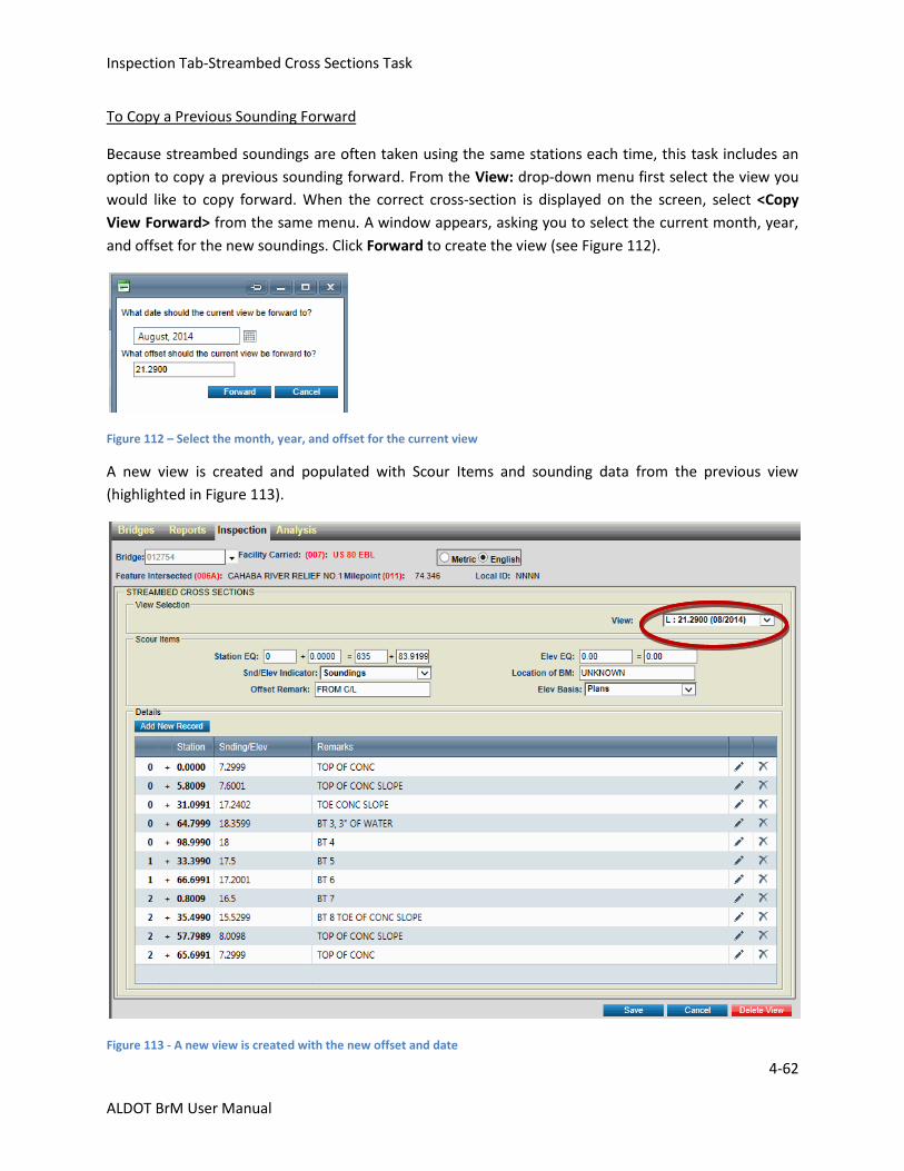
Inspection Tab-Streambed Cross Sections Task
4-62
ALDOT BrM User Manual
To Copy a Previous Sounding Forward
Because streambed soundings are often taken using the same stations each time, this task includes an
option to copy a previous sounding forward. From the View: drop-down menu first select the view you
would like to copy forward. When the correct cross-section is displayed on the screen, select <Copy
View Forward> from the same menu. A window appears, asking you to select the current month, year,
and offset for the new soundings. Click Forward to create the view (see Figure 112).
Figure 112 – Select the month, year, and offset for the current view
A new view is created and populated with Scour Items and sounding data from the previous view
(highlighted in Figure 113).
Figure 113 - A new view is created with the new offset and date
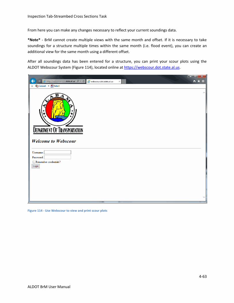
Inspection Tab-Streambed Cross Sections Task
4-63
ALDOT BrM User Manual
From here you can make any changes necessary to reflect your current soundings data.
*Note* - BrM cannot create multiple views with the same month and offset. If it is necessary to take
soundings for a structure multiple times within the same month (i.e. flood event), you can create an
additional view for the same month using a different offset.
After all soundings data has been entered for a structure, you can print your scour plots using the
ALDOT Webscour System (Figure 114), located online at https://webscour.dot.state.al.us.
Figure 114 - Use Webscour to view and print scour plots

Inspection Tab-Streambed Cross Sections Task
4-64
ALDOT BrM User Manual
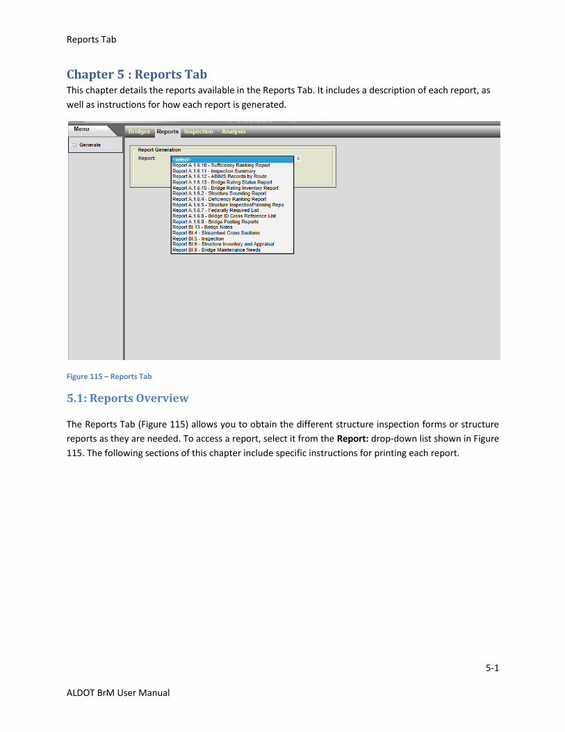
Reports Tab
5-1
ALDOT BrM User Manual
Chapter 5 : Reports Tab This chapter details the reports available in the Reports Tab. It includes a description of each report, as
well as instructions for how each report is generated.
Figure 115 – Reports Tab
5.1: Reports Overview
The Reports Tab (Figure 115) allows you to obtain the different structure inspection forms or structure
reports as they are needed. To access a report, select it from the Report: drop-down list shown in Figure
115. The following sections of this chapter include specific instructions for printing each report.
Reports Tab-Inspection Forms
5-2
ALDOT BrM User Manual
5.2: Inspection Forms
This screen allows you to obtain different structure inspection forms. The available forms are the:
Streambed Cross Sections (BI-4) form
Inspection (BI-5) form
Structure Inventory and Appraisal (BI-6) form
Bridge Maintenance Needs (BI-9) form
Bridge Notes (BI-13) form
For more information about each form, see the ALDOT Bridge Inspection Manual.
Forms can be generated and printed for a particular structure or groups of structures. If you plan on
printing forms for multiple structures at once, first select those structures from the Bridges Tab. See
Chapter 3.1: View List Task for more about selecting a structure.
To access the standard inspection forms, click the Reports Tab and select the desired report from the
drop-down menu. The Report Generation screen opens. Select a format as well as the structure(s) the
form should print for.

Reports Tab-Inspection Forms
5-3
ALDOT BrM User Manual
BI-4 Streambed Cross Sections
The BI-4 Streambed Cross Sections form (Figure 116) was created for the collection of data in order to
produce streambed cross sections to be included on the scour plots. This form must be completed
during routine inspections for all scour potential bridges.
Figure 116 - BI-4 Streambed Cross Section Report Generation screen
Use the radio buttons at the top of your screen to select a format. Reports can be printed in various
formats (PDF, Text, Excel, RTF, Word, and HTML).
Next, select which structures the form should print for in the Batch Key field. You can choose to print
forms for all structures in the inventory, all selected structures, the most recent structure selected, or
another bridge. If you choose all selected structures, the report includes all structures selected in the
Bridges Tab prior to entering the Reports Tab. If you choose to print for another bridge, type the 6-digit
BIN into the space provided.
After selecting a format and a set of criteria, click Generate Report. The report downloads, allowing
saving or printing as needed. To return to the previous page, click Return to Report Generation.
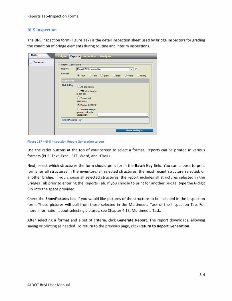
Reports Tab-Inspection Forms
5-4
ALDOT BrM User Manual
BI-5 Inspection
The BI-5 Inspection form (Figure 117) is the detail inspection sheet used by bridge inspectors for grading
the condition of bridge elements during routine and interim inspections.
Figure 117 – BI-5 Inspection Report Generation screen
Use the radio buttons at the top of your screen to select a format. Reports can be printed in various
formats (PDF, Text, Excel, RTF, Word, and HTML).
Next, select which structures the form should print for in the Batch Key field. You can choose to print
forms for all structures in the inventory, all selected structures, the most recent structure selected, or
another bridge. If you choose all selected structures, the report includes all structures selected in the
Bridges Tab prior to entering the Reports Tab. If you choose to print for another bridge, type the 6-digit
BIN into the space provided.
Check the ShowPictures box if you would like pictures of the structure to be included in the inspection
form. These pictures will pull from those selected in the Multimedia Task of the Inspection Tab. For
more information about selecting pictures, see Chapter 4.13: Multimedia Task.
After selecting a format and a set of criteria, click Generate Report. The report downloads, allowing
saving or printing as needed. To return to the previous page, click Return to Report Generation.

Reports Tab-Inspection Forms
5-5
ALDOT BrM User Manual
BI-6 Structure Inventory and Appraisal
The BI-6 Structure Inventory and Appraisal form (Figure 118) contains structure inventory and appraisal
data collected during bridge inspections. Most of the information in this form, once coded, is not likely
to change over the life of the structure but should be updated as needed during each routine inspection.
Figure 118 - BI-6 Structure Inventory and Appraisal Report Generation screen
Use the radio buttons at the top of your screen to select a format. Reports can be printed in various
formats (PDF, Text, Excel, RTF, Word, and HTML).
Next, select which structures the form should print for in the Batch Key field. You can choose to print
forms for all structures in the inventory, all selected structures, the most recent structure selected, or
another bridge. If you choose all selected structures, the report includes all structures selected in the
Bridges Tab prior to entering the Reports Tab. If you choose to print for another bridge, type the 6-digit
BIN into the space provided.
By default, the BI-6 only prints for the “On” roadway type associated with the structure. If the structure
includes “Under” roadways, check the Display All Roadway box to include all roadway types in the form.
After selecting a format and a set of criteria, click Generate Report. The report downloads, allowing
saving or printing as needed. To return to the previous page, click Return to Report Generation.
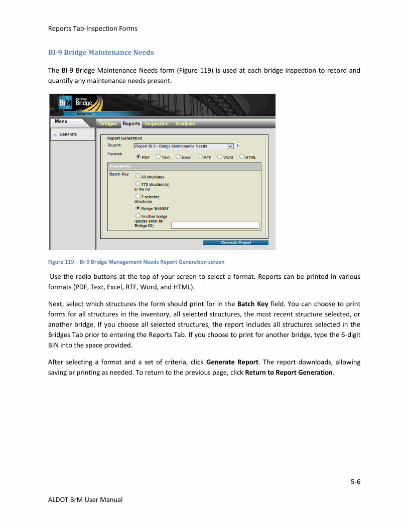
Reports Tab-Inspection Forms
5-6
ALDOT BrM User Manual
BI-9 Bridge Maintenance Needs
The BI-9 Bridge Maintenance Needs form (Figure 119) is used at each bridge inspection to record and
quantify any maintenance needs present.
Figure 119 – BI-9 Bridge Management Needs Report Generation screen
Use the radio buttons at the top of your screen to select a format. Reports can be printed in various
formats (PDF, Text, Excel, RTF, Word, and HTML).
Next, select which structures the form should print for in the Batch Key field. You can choose to print
forms for all structures in the inventory, all selected structures, the most recent structure selected, or
another bridge. If you choose all selected structures, the report includes all structures selected in the
Bridges Tab prior to entering the Reports Tab. If you choose to print for another bridge, type the 6-digit
BIN into the space provided.
After selecting a format and a set of criteria, click Generate Report. The report downloads, allowing
saving or printing as needed. To return to the previous page, click Return to Report Generation.
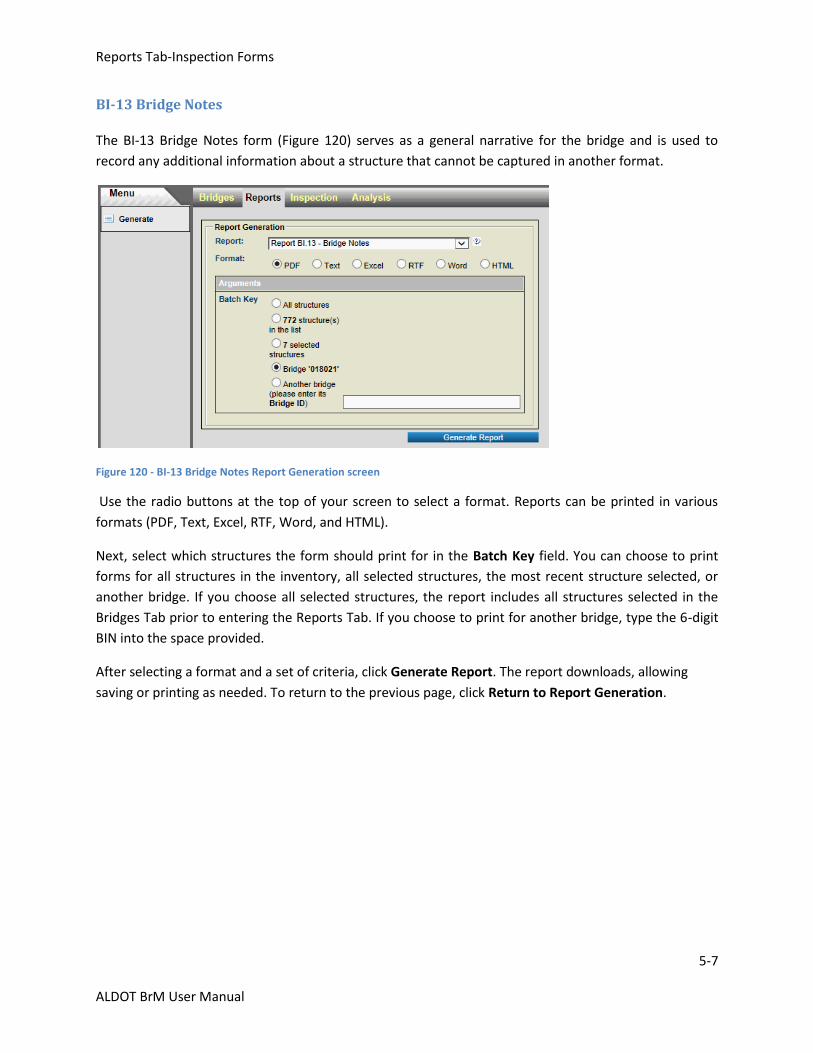
Reports Tab-Inspection Forms
5-7
ALDOT BrM User Manual
BI-13 Bridge Notes
The BI-13 Bridge Notes form (Figure 120) serves as a general narrative for the bridge and is used to
record any additional information about a structure that cannot be captured in another format.
Figure 120 - BI-13 Bridge Notes Report Generation screen
Use the radio buttons at the top of your screen to select a format. Reports can be printed in various
formats (PDF, Text, Excel, RTF, Word, and HTML).
Next, select which structures the form should print for in the Batch Key field. You can choose to print
forms for all structures in the inventory, all selected structures, the most recent structure selected, or
another bridge. If you choose all selected structures, the report includes all structures selected in the
Bridges Tab prior to entering the Reports Tab. If you choose to print for another bridge, type the 6-digit
BIN into the space provided.
After selecting a format and a set of criteria, click Generate Report. The report downloads, allowing
saving or printing as needed. To return to the previous page, click Return to Report Generation.
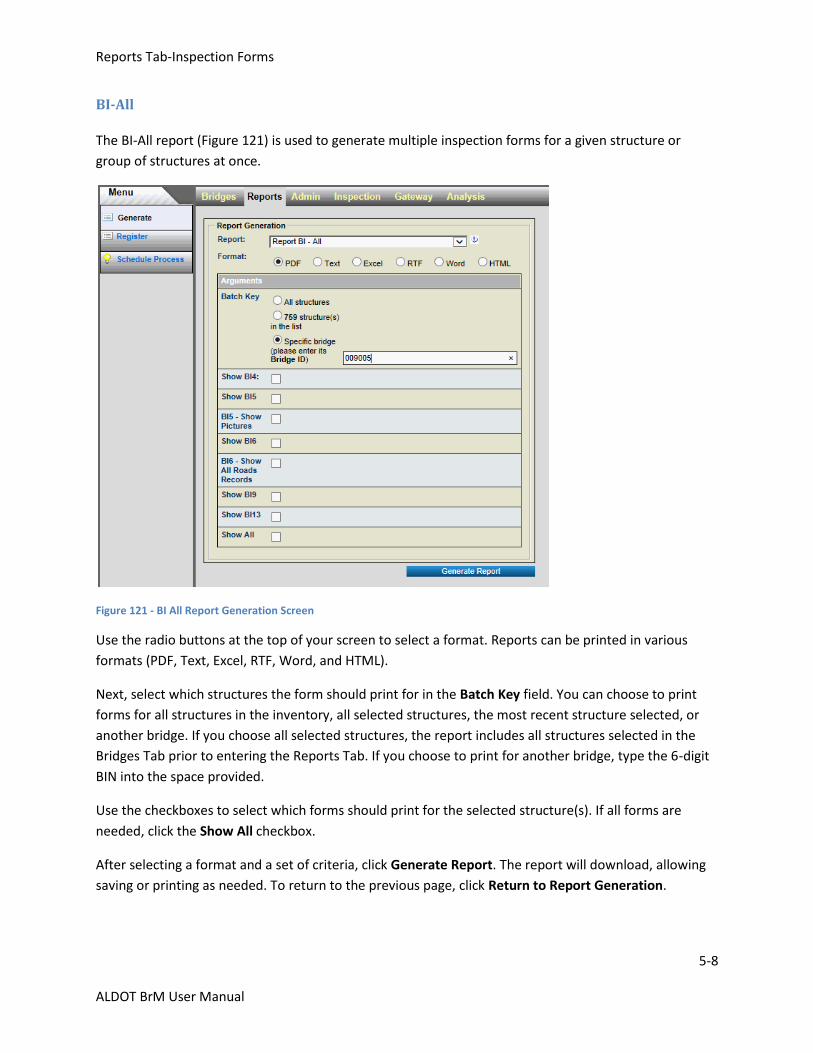
Reports Tab-Inspection Forms
5-8
ALDOT BrM User Manual
BI-All
The BI-All report (Figure 121) is used to generate multiple inspection forms for a given structure or
group of structures at once.
Figure 121 - BI All Report Generation Screen
Use the radio buttons at the top of your screen to select a format. Reports can be printed in various
formats (PDF, Text, Excel, RTF, Word, and HTML).
Next, select which structures the form should print for in the Batch Key field. You can choose to print
forms for all structures in the inventory, all selected structures, the most recent structure selected, or
another bridge. If you choose all selected structures, the report includes all structures selected in the
Bridges Tab prior to entering the Reports Tab. If you choose to print for another bridge, type the 6-digit
BIN into the space provided.
Use the checkboxes to select which forms should print for the selected structure(s). If all forms are
needed, click the Show All checkbox.
After selecting a format and a set of criteria, click Generate Report. The report will download, allowing
saving or printing as needed. To return to the previous page, click Return to Report Generation.
Reports Tab-Structure Reports
5-9
ALDOT BrM User Manual
5.3: Structure Reports
To access the standard structure reports, click the Reports Tab and select the desired report from the
drop-down menu. The Report Generation Screen opens, allowing you to select the report criteria, which
vary by report. Individual report criteria are discussed later in this chapter.
The following reports should be generated prior to a Bridge Inspection Compliance Review:
A.1.6.2 – Structure Sounding Report
A.1.6.5 – Structure Inspection Planning Report
A.1.6.7 – Federally Required Lists
A.1.6.8 – Bridge ID Cross Reference List
A.1.6.9 – Bridge Posting Report
A.1.6.15 – Rating Inventory Report
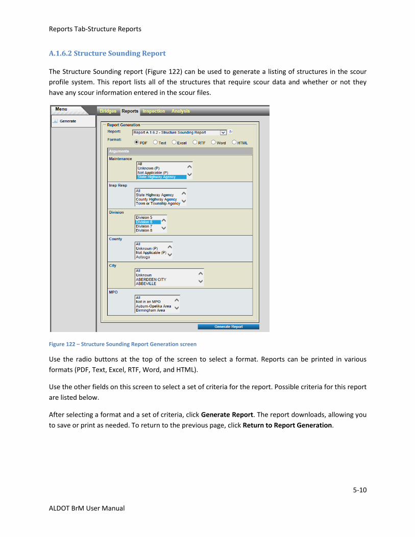
Reports Tab-Structure Reports
5-10
ALDOT BrM User Manual
A.1.6.2 Structure Sounding Report
The Structure Sounding report (Figure 122) can be used to generate a listing of structures in the scour
profile system. This report lists all of the structures that require scour data and whether or not they
have any scour information entered in the scour files.
Figure 122 – Structure Sounding Report Generation screen
Use the radio buttons at the top of the screen to select a format. Reports can be printed in various
formats (PDF, Text, Excel, RTF, Word, and HTML).
Use the other fields on this screen to select a set of criteria for the report. Possible criteria for this report
are listed below.
After selecting a format and a set of criteria, click Generate Report. The report downloads, allowing you
to save or print as needed. To return to the previous page, click Return to Report Generation.

Reports Tab-Structure Reports
5-11
ALDOT BrM User Manual
Possible criteria for the Structure Sounding report are:
Maintenance: This field specifies the maintenance responsibility (Item 21) of the structures for which the report is to be printed.
Insp Resp: This field specifies the inspection responsibility (Item 293) of the structures for which the report is to be printed.
Division:
This field specifies the ALDOT Division/Area location (Item 2) of the structures for which the report is to be printed. If this field is entered, then only the structures in the selected division print.
County: This field specifies the county location (Item 3) of the structures for which the report is to be printed. This field lists all counties in the state in alphabetical order. If this field is entered, then only the structures in the selected county print.
City: This field specifies the city location (Item 4) of the structures for which the report is to be printed. This field lists all cities in the state in alphabetical order and if entered, only the structures in the selected city will print.
MPO:
This field shows the MPO location (Item 203) of the structures for which the report is to be printed.
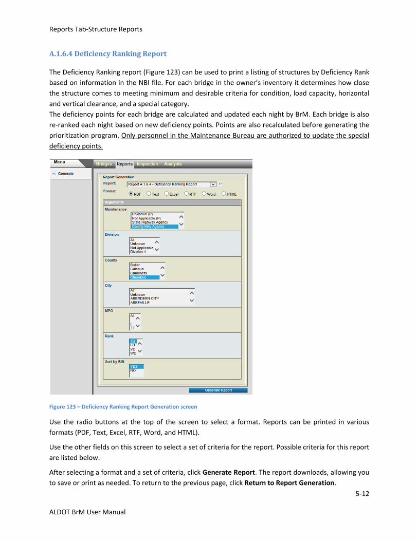
Reports Tab-Structure Reports
5-12
ALDOT BrM User Manual
A.1.6.4 Deficiency Ranking Report
The Deficiency Ranking report (Figure 123) can be used to print a listing of structures by Deficiency Rank
based on information in the NBI file. For each bridge in the owner’s inventory it determines how close
the structure comes to meeting minimum and desirable criteria for condition, load capacity, horizontal
and vertical clearance, and a special category.
The deficiency points for each bridge are calculated and updated each night by BrM. Each bridge is also
re-ranked each night based on new deficiency points. Points are also recalculated before generating the
prioritization program. Only personnel in the Maintenance Bureau are authorized to update the special
deficiency points.
Figure 123 – Deficiency Ranking Report Generation screen
Use the radio buttons at the top of the screen to select a format. Reports can be printed in various
formats (PDF, Text, Excel, RTF, Word, and HTML).
Use the other fields on this screen to select a set of criteria for the report. Possible criteria for this report
are listed below.
After selecting a format and a set of criteria, click Generate Report. The report downloads, allowing you
to save or print as needed. To return to the previous page, click Return to Report Generation.
Reports Tab-Structure Reports
5-13
ALDOT BrM User Manual
Possible criteria for the Deficiency Ranking report are:
Maintenance: This field specifies the maintenance responsibility (Item 21) of the structures for which the report is to be printed.
Division: This field specifies the ALDOT Division/Area location (Item 2) of the structures for which the report is to be printed. If this field is entered, then only the structures in the selected division print.
County: This field specifies the county location (Item 3) of the structures for which the report is to be printed. This field lists all counties in the state in alphabetical order. If this field is entered, then only the structures in the selected county print.
City: This field specifies the city location (Item 4) of the structures for which the report is to be printed. This field lists all cities in the state in alphabetical order. If this field is entered, then only the structures in the selected city print.
MPO: This field specifies the MPO location (Item 203) of the structures for which the report is to be printed.
Rank: This field specifies one weighting factor for each deficiency category of total deficiency (TD), load deficiency (LD), vertical clearance deficiency (VD), width deficiency (WD), condition deficiency (CD), and statewide deficiency (SD).
Sort by BIN: This field specifies the order in which structures should be listed on the report. Select YES to sort by BIN, or select NO to sort by Rank.
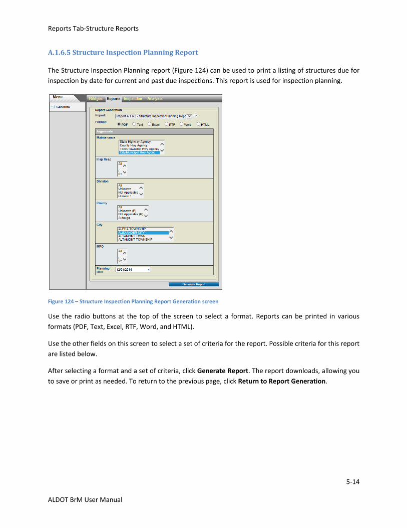
Reports Tab-Structure Reports
5-14
ALDOT BrM User Manual
A.1.6.5 Structure Inspection Planning Report
The Structure Inspection Planning report (Figure 124) can be used to print a listing of structures due for
inspection by date for current and past due inspections. This report is used for inspection planning.
Figure 124 – Structure Inspection Planning Report Generation screen
Use the radio buttons at the top of the screen to select a format. Reports can be printed in various
formats (PDF, Text, Excel, RTF, Word, and HTML).
Use the other fields on this screen to select a set of criteria for the report. Possible criteria for this report
are listed below.
After selecting a format and a set of criteria, click Generate Report. The report downloads, allowing you
to save or print as needed. To return to the previous page, click Return to Report Generation.
Reports Tab-Structure Reports
5-15
ALDOT BrM User Manual
Possible criteria for the Structure Inspection Planning Report are:
Maintenance: This field specifies the maintenance responsibility (Item 21) of the structures for which the report is to be printed.
Insp Resp: This field specifies the inspection responsibility (Item 293) of the structures for which the report is to be printed.
Division: This field specifies the ALDOT Division/Area location (Item 2) of the structures for which the report is to be printed. If this field is entered, then only the structures in the selected division print.
County: This field specifies the county location (Item 3) of the structures for which the report is to be printed. This field lists all counties in the state in alphabetical order. If this field is entered, then only the structures in the selected county print.
City: This field specifies the city location (Item 4) of the structures for which the report is to be printed. This field lists all cities in the state in alphabetical order. If this field is entered, then only the structures in the selected city print.
MPO: This field specifies the MPO location (Item 203) of the structures for which the report is to be printed.
Planning Date:
This field specifies the date of inspection. The report runs through the end of the selected month, but
the date must be in MM/DD/YYYY format. For example, to see all structures due for an inspection
through December 2014, the date 12/01/2014 should be entered. This field is always required.
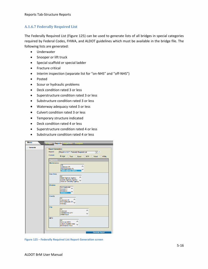
Reports Tab-Structure Reports
5-16
ALDOT BrM User Manual
A.1.6.7 Federally Required List
The Federally Required List (Figure 125) can be used to generate lists of all bridges in special categories
required by Federal Codes, FHWA, and ALDOT guidelines which must be available in the bridge file. The
following lists are generated:
Underwater
Snooper or lift truck
Special scaffold or special ladder
Fracture critical
Interim inspection (separate list for “on-NHS” and “off-NHS”)
Posted
Scour or hydraulic problems
Deck condition rated 3 or less
Superstructure condition rated 3 or less
Substructure condition rated 3 or less
Waterway adequacy rated 3 or less
Culvert condition rated 3 or less
Temporary structure indicated
Deck condition rated 4 or less
Superstructure condition rated 4 or less
Substructure condition rated 4 or less
Figure 125 – Federally Required List Report Generation screen
Reports Tab-Structure Reports
5-17
ALDOT BrM User Manual
Use the radio buttons at the top of the screen to select a format. Reports can be printed in various
formats (PDF, Text, Excel, RTF, Word, and HTML).
Use the other fields on this screen to select a set of criteria for the report. Possible criteria for this report
are listed below.
After selecting a format and a set of criteria, click Generate Report. The report downloads, allowing you
to save or print as needed. To return to the previous page, click Return to Report Generation.
Possible criteria for the Federally Required List are:
Maintenance:
This field specifies the maintenance responsibility (Item 21) of the structures for which the report is to be printed.
Insp Resp:
This field specifies the inspection responsibility (Item 293) of the structures for which the report is to be printed.
Division:
This field specifies the ALDOT Division/Area location (Item 2) of the structures for which the report is to be printed. If this field is entered, then only the structures in the selected division print.
County:
This field specifies the county location (Item 3) of the structures for which the report is to be printed.
This field lists all counties in the state in alphabetical order. If this field is entered, then only the
structures in the selected county print.
City:
This field specifies the city location (Item 4) of the structures for which the report is to be printed. This field lists all cities in the state in alphabetical order. If this field is entered, then only the structures in the selected city print.
MPO:
This field specifies the MPO location (Item 203) of the structures for which the report is to be printed.
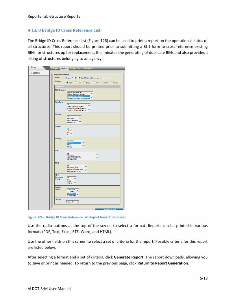
Reports Tab-Structure Reports
5-18
ALDOT BrM User Manual
A.1.6.8 Bridge ID Cross Reference List
The Bridge ID Cross Reference List (Figure 126) can be used to print a report on the operational status of
all structures. This report should be printed prior to submitting a BI-1 form to cross-reference existing
BINs for structures up for replacement. It eliminates the generating of duplicate BINs and also provides a
listing of structures belonging to an agency.
Figure 126 – Bridge ID Cross Reference List Report Generation screen
Use the radio buttons at the top of the screen to select a format. Reports can be printed in various
formats (PDF, Text, Excel, RTF, Word, and HTML).
Use the other fields on this screen to select a set of criteria for the report. Possible criteria for this report
are listed below.
After selecting a format and a set of criteria, click Generate Report. The report downloads, allowing you
to save or print as needed. To return to the previous page, click Return to Report Generation.

Reports Tab-Structure Reports
5-19
ALDOT BrM User Manual
Possible criteria for the Bridge ID Cross Reference List include:
Maintenance: This field specifies the maintenance responsibility (Item 21) of the structures for which the report is to be printed.
Insp Resp: This field specifies the inspection responsibility (Item 293) of the structures for which the report is to be printed.
Division: This field specifies the ALDOT Division/Area location (Item 2) of the structures for which the report is to be printed. If this field is entered, then only the structures in the selected division print.
District:
This field specifies the ALDOT District location of the structures for which the report is to be printed. If
this field is entered, then only the structures in the selected district print.
County: This field specifies the county location (Item 3) of the structures for which the report is to be printed. This field lists all counties in the state in alphabetical order. If this field is entered, then only the structures in the selected county print.
City: This field specifies the city location (Item 4) of the structures for which the report is to be printed. This field lists all cities in the state in alphabetical order. If this field is entered, then only the structures in the selected city print.
MPO:
This field specifies the MPO location (Item 202) of the structures for which the report is to be printed.
LRS Inventory Route:
This field specifies the LRS inventory route number (Item 13) of the bridges for which a report should be
printed.
Bridge Status:
This field specifies the operational status of a structure. This field is always required. Options are:
0 All Include all operational statuses
1 Inactive Structure not in-service (either removed or closed permanently)
3 Active Structure is currently in-service and open to traffic
4 Proposed Structure is planned, under design/construction, or otherwise not in-service
Sort By:
This field specifies which order you want the structure information in the report printed. By choosing an
option in this drop-down menu, the report prints structures in order of Structure ID, Bridge ID (BIN), or
Local ID number. This field is always required.

Reports Tab-Structure Reports
5-20
ALDOT BrM User Manual
A.1.6.9 Bridge Posting Reports
The Bridge Posting report (Figure 127) allows the user to review the posting status of all structures in
their inventory.
Figure 127 – Bridge Posting Reports Generation screen
Use the radio buttons at the top of the screen to select a format. Reports can be printed in various
formats (PDF, Text, Excel, RTF, Word, and HTML).
Use the other fields on this screen to select a set of criteria for the report. Possible criteria for this report
are listed below.
After selecting a format and a set of criteria, click Generate Report. The report downloads, allowing you
to save or print as needed. To return to the previous page, click Return to Report Generation.
Reports Tab-Structure Reports
5-21
ALDOT BrM User Manual
Possible criteria for the Bridge Posting Report are:
Maintenance: This field specifies the maintenance responsibility (Item 21) of the structures for which the report is to be printed.
Division: This field specifies the ALDOT Division/Area location (Item 2) of the structures for which the report is to be printed. If this field is entered, then only the structures in the selected division print.
District:
This field specifies the ALDOT District location of the structures for which the report is to be printed. If
this field is entered, then only the structures in the selected district print.
County: This field specifies the county location (Item 3) of the structures for which the report is to be printed. This field lists all counties in the state in alphabetical order. If this field is entered, then only the structures in the selected county print.
City: This field specifies the city location (Item 4) of the structures for which the report is to be printed. This field lists all cities in the state in alphabetical order. If this field is entered, then only the structures in the selected city print.
LRS Inventory Route:
This field specifies the LRS inventory route number (Item 13) of the bridges for which a report should be
printed.
Sort By:
This field specifies which order you want the structure information in the report printed. By choosing an
option in this drop down menu, the report prints structures in order of Structure ID, Bridge ID (BIN), or
Local ID number. This field is always required.
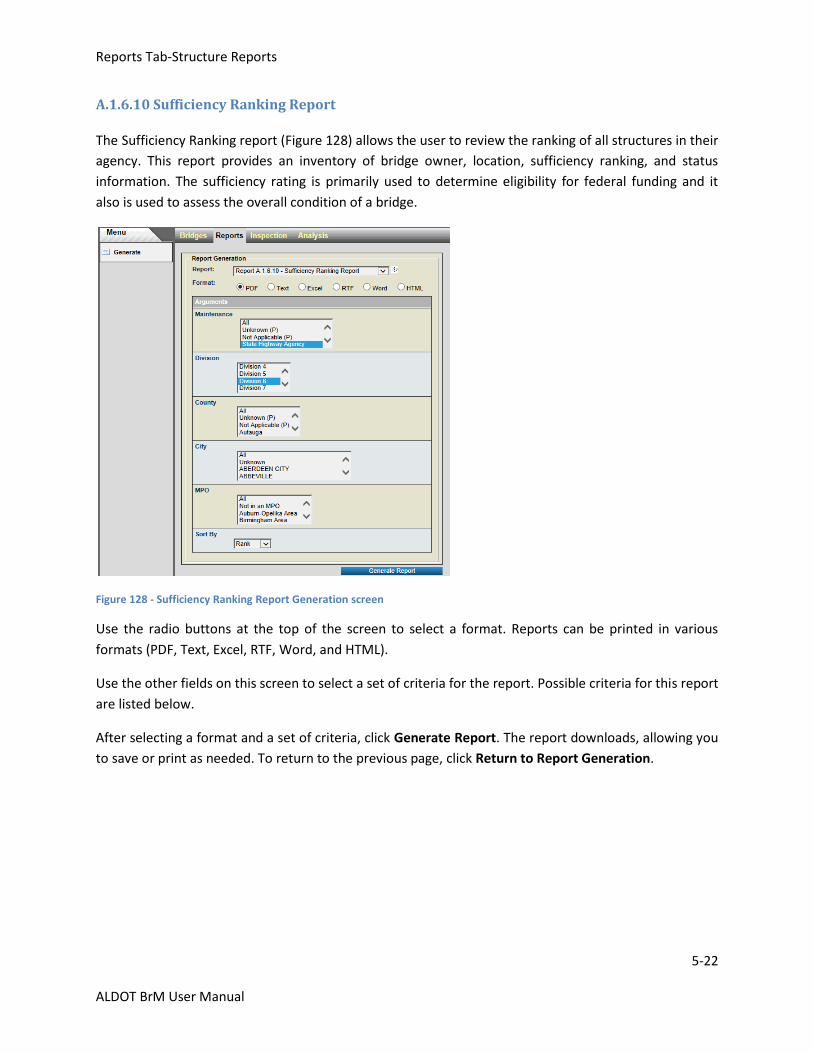
Reports Tab-Structure Reports
5-22
ALDOT BrM User Manual
A.1.6.10 Sufficiency Ranking Report
The Sufficiency Ranking report (Figure 128) allows the user to review the ranking of all structures in their
agency. This report provides an inventory of bridge owner, location, sufficiency ranking, and status
information. The sufficiency rating is primarily used to determine eligibility for federal funding and it
also is used to assess the overall condition of a bridge.
Figure 128 - Sufficiency Ranking Report Generation screen
Use the radio buttons at the top of the screen to select a format. Reports can be printed in various
formats (PDF, Text, Excel, RTF, Word, and HTML).
Use the other fields on this screen to select a set of criteria for the report. Possible criteria for this report
are listed below.
After selecting a format and a set of criteria, click Generate Report. The report downloads, allowing you
to save or print as needed. To return to the previous page, click Return to Report Generation.
Reports Tab-Structure Reports
5-23
ALDOT BrM User Manual
Possible criteria for the Sufficiency Status Report are:
Maintenance: This field specifies the maintenance responsibility (Item 21) of the structures for which the report is to be printed.
Division: This field specifies the ALDOT Division/Area location (Item 2) of the structures for which the report is to be printed. If this field is entered, then only the structures in the selected division print.
County: This field specifies the county location (Item 3) of the structures for which the report is to be printed. This field lists all counties in the state in alphabetical order. If this field is entered, then only the structures in the selected county print.
City: This field specifies the city location (Item 4) of the structures for which the report is to be printed. This field lists all cities in the state in alphabetical order. If this field is entered, then only the structures in the selected city print.
MPO:
This field specifies the MPO location (Item 203) of the structures for which the report is to be printed.
Sort By:
This field specifies which order you want the structure information in the report printed. By choosing an
option in this drop down menu, the report prints structures in order of Structure ID, Bridge ID (BIN), or
Local ID number. This field is always required.
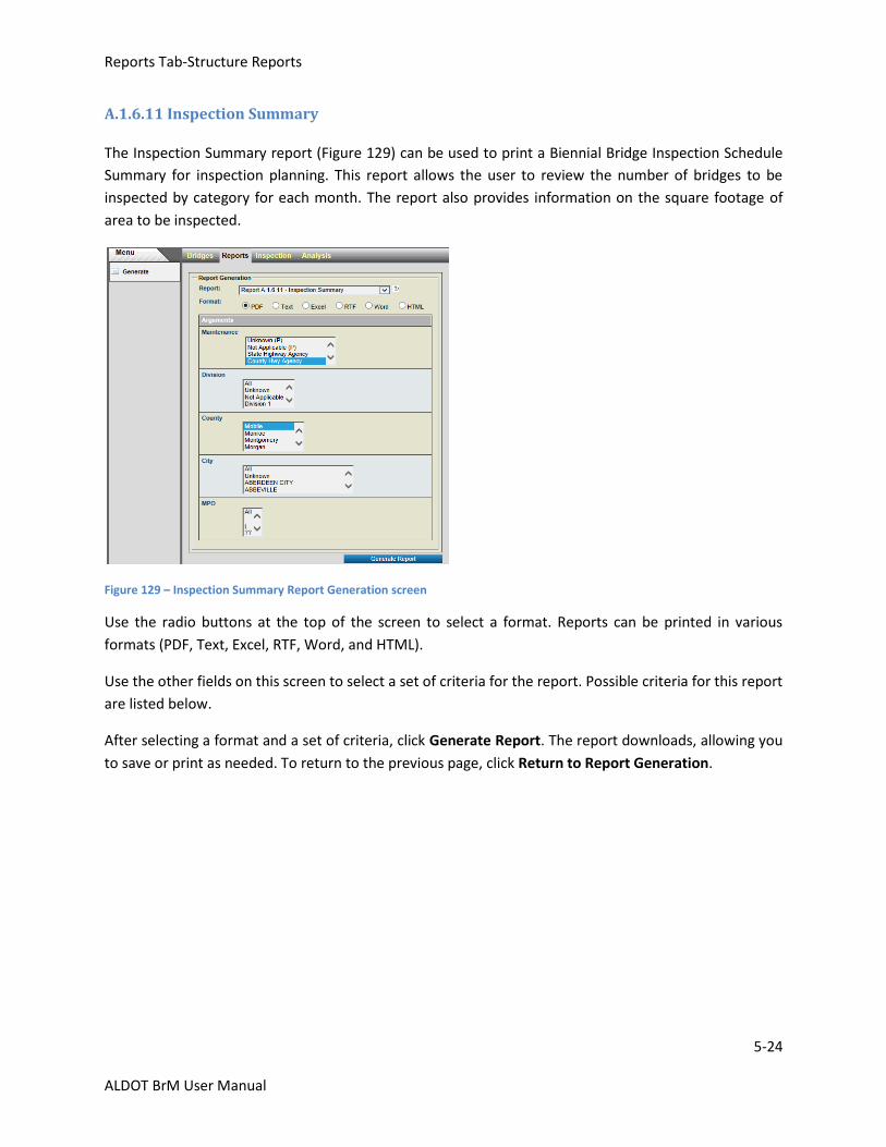
Reports Tab-Structure Reports
5-24
ALDOT BrM User Manual
A.1.6.11 Inspection Summary
The Inspection Summary report (Figure 129) can be used to print a Biennial Bridge Inspection Schedule
Summary for inspection planning. This report allows the user to review the number of bridges to be
inspected by category for each month. The report also provides information on the square footage of
area to be inspected.
Figure 129 – Inspection Summary Report Generation screen
Use the radio buttons at the top of the screen to select a format. Reports can be printed in various
formats (PDF, Text, Excel, RTF, Word, and HTML).
Use the other fields on this screen to select a set of criteria for the report. Possible criteria for this report
are listed below.
After selecting a format and a set of criteria, click Generate Report. The report downloads, allowing you
to save or print as needed. To return to the previous page, click Return to Report Generation.
Reports Tab-Structure Reports
5-25
ALDOT BrM User Manual
Possible criteria for the Inspection Summary Report are:
Maintenance: This field specifies the maintenance responsibility (Item 21) of the structures for which the report is to be printed.
Division: This field specifies the ALDOT Division/Area location (Item 2) of the structures for which the report is to be printed. If this field is entered, then only the structures in the selected division print.
County: This field specifies the county location (Item 3) of the structures for which the report is to be printed. This field lists all counties in the state in alphabetical order. If this field is entered, then only the structures in the selected county print.
City: This field specifies the city location (Item 4) of the structures for which the report is to be printed. This field lists all cities in the state in alphabetical order. If this field is entered, then only the structures in the selected city print.
MPO:
This field specifies the MPO location (Item 203) of the structures for which the report is to be printed.
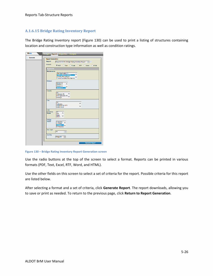
Reports Tab-Structure Reports
5-26
ALDOT BrM User Manual
A.1.6.15 Bridge Rating Inventory Report
The Bridge Rating Inventory report (Figure 130) can be used to print a listing of structures containing
location and construction type information as well as condition ratings.
Figure 130 – Bridge Rating Inventory Report Generation screen
Use the radio buttons at the top of the screen to select a format. Reports can be printed in various
formats (PDF, Text, Excel, RTF, Word, and HTML).
Use the other fields on this screen to select a set of criteria for the report. Possible criteria for this report
are listed below.
After selecting a format and a set of criteria, click Generate Report. The report downloads, allowing you
to save or print as needed. To return to the previous page, click Return to Report Generation.
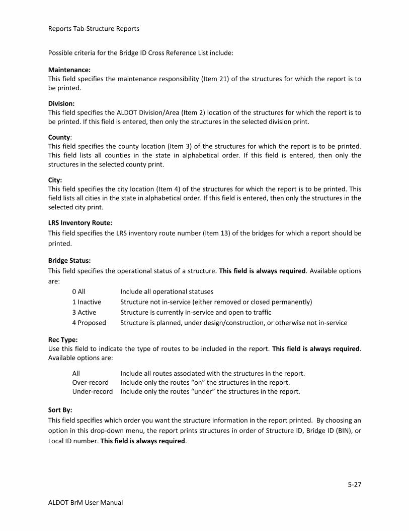
Reports Tab-Structure Reports
5-27
ALDOT BrM User Manual
Possible criteria for the Bridge ID Cross Reference List include:
Maintenance: This field specifies the maintenance responsibility (Item 21) of the structures for which the report is to be printed.
Division: This field specifies the ALDOT Division/Area (Item 2) location of the structures for which the report is to be printed. If this field is entered, then only the structures in the selected division print.
County: This field specifies the county location (Item 3) of the structures for which the report is to be printed. This field lists all counties in the state in alphabetical order. If this field is entered, then only the structures in the selected county print.
City: This field specifies the city location (Item 4) of the structures for which the report is to be printed. This field lists all cities in the state in alphabetical order. If this field is entered, then only the structures in the selected city print.
LRS Inventory Route:
This field specifies the LRS inventory route number (Item 13) of the bridges for which a report should be
printed.
Bridge Status:
This field specifies the operational status of a structure. This field is always required. Available options
are:
0 All Include all operational statuses
1 Inactive Structure not in-service (either removed or closed permanently)
3 Active Structure is currently in-service and open to traffic
4 Proposed Structure is planned, under design/construction, or otherwise not in-service
Rec Type: Use this field to indicate the type of routes to be included in the report. This field is always required. Available options are:
All Include all routes associated with the structures in the report. Over-record Include only the routes “on” the structures in the report.
Under-record Include only the routes “under” the structures in the report.
Sort By:
This field specifies which order you want the structure information in the report printed. By choosing an
option in this drop-down menu, the report prints structures in order of Structure ID, Bridge ID (BIN), or
Local ID number. This field is always required.
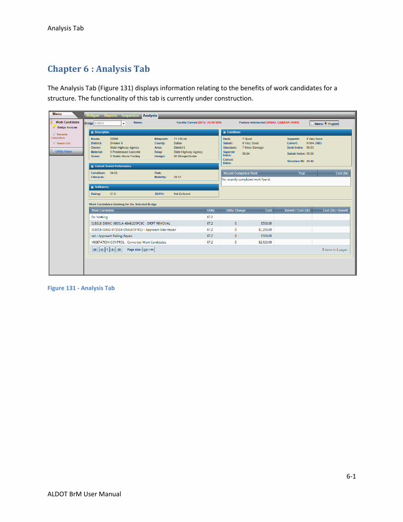
Analysis Tab
6-1
ALDOT BrM User Manual
Chapter 6 : Analysis Tab
The Analysis Tab (Figure 131) displays information relating to the benefits of work candidates for a
structure. The functionality of this tab is currently under construction.
Figure 131 - Analysis Tab