Embed Size (px)
Citation preview
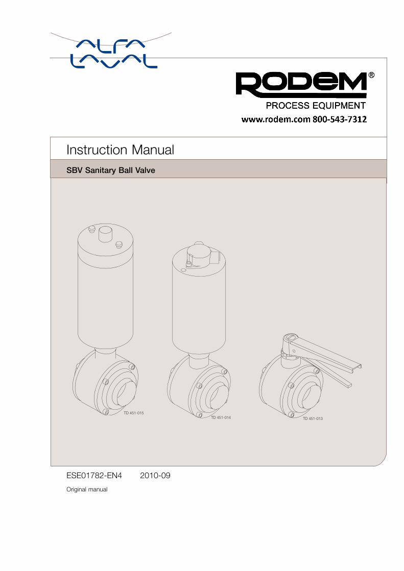
Instruction ManualSBV Sanitary Ball Valve
TD 451-013
ESE01782-EN4 2010-09
Original manual

Table of contents
The information herein is correct at the time of issue but may be subject to change without prior notice
1. Declaration of Conformity .. . . . . . . . . . . . . . . . . . . . . . . . . . . . . . . . . . . . . . . . . . . . . . . . . . . . . . . . . . . . . . . . . . . . . . . . . . 4
2. Safety .. . . . . . . . . . . . . . . . . . . . . . . . . . . . . . . . . . . . . . . . . . . . . . . . . . . . . . . . . . . . . . . . . . . . . . . . . . . . . . . . . . . . . . . . . . . . . . . . . . . 52.1. Important information ... . . . . . . . . . . . . . . . . . . . . . . . . . . . . . . . . . . . . . . . . . . . . . . . . . . . . . . . . . . . . . . . . . . . . . . . . . . 52.2. Warning signs ... . . . . . . . . . . . . . . . . . . . . . . . . . . . . . . . . . . . . . . . . . . . . . . . . . . . . . . . . . . . . . . . . . . . . . . . . . . . . . . . . . . 52.3. Safety precautions ... . . . . . . . . . . . . . . . . . . . . . . . . . . . . . . . . . . . . . . . . . . . . . . . . . . . . . . . . . . . . . . . . . . . . . . . . . . . . . 6
3. Installation .. . . . . . . . . . . . . . . . . . . . . . . . . . . . . . . . . . . . . . . . . . . . . . . . . . . . . . . . . . . . . . . . . . . . . . . . . . . . . . . . . . . . . . . . . . . . . 73.1. Unpacking/Delivery /General installation ... . . . . . . . . . . . . . . . . . . . . . . . . . . . . . . . . . . . . . . . . . . . . . . . . . . . . 73.2. General installation ... . . . . . . . . . . . . . . . . . . . . . . . . . . . . . . . . . . . . . . . . . . . . . . . . . . . . . . . . . . . . . . . . . . . . . . . . . . . . . 83.3. Welding .. . . . . . . . . . . . . . . . . . . . . . . . . . . . . . . . . . . . . . . . . . . . . . . . . . . . . . . . . . . . . . . . . . . . . . . . . . . . . . . . . . . . . . . . . . . 93.4. Indication and control equipment (optional extras) . . . . . . . . . . . . . . . . . . . . . . . . . . . . . . . . . . . . . . . . . . . . 10
4. Operation .. . . . . . . . . . . . . . . . . . . . . . . . . . . . . . . . . . . . . . . . . . . . . . . . . . . . . . . . . . . . . . . . . . . . . . . . . . . . . . . . . . . . . . . . . . . . . . 124.1. Operation .. . . . . . . . . . . . . . . . . . . . . . . . . . . . . . . . . . . . . . . . . . . . . . . . . . . . . . . . . . . . . . . . . . . . . . . . . . . . . . . . . . . . . . . . . 124.2. Fault finding .. . . . . . . . . . . . . . . . . . . . . . . . . . . . . . . . . . . . . . . . . . . . . . . . . . . . . . . . . . . . . . . . . . . . . . . . . . . . . . . . . . . . . 134.3. Recommended cleaning .. . . . . . . . . . . . . . . . . . . . . . . . . . . . . . . . . . . . . . . . . . . . . . . . . . . . . . . . . . . . . . . . . . . . . . . . 14
5. Maintenance ... . . . . . . . . . . . . . . . . . . . . . . . . . . . . . . . . . . . . . . . . . . . . . . . . . . . . . . . . . . . . . . . . . . . . . . . . . . . . . . . . . . . . . . . . 165.1. General maintenance ... . . . . . . . . . . . . . . . . . . . . . . . . . . . . . . . . . . . . . . . . . . . . . . . . . . . . . . . . . . . . . . . . . . . . . . . . . . 165.2. Replacement of product wetted seals ... . . . . . . . . . . . . . . . . . . . . . . . . . . . . . . . . . . . . . . . . . . . . . . . . . . . . . . . 185.3. Replacement of all seals .. . . . . . . . . . . . . . . . . . . . . . . . . . . . . . . . . . . . . . . . . . . . . . . . . . . . . . . . . . . . . . . . . . . . . . . . 19
6. Technical data .. . . . . . . . . . . . . . . . . . . . . . . . . . . . . . . . . . . . . . . . . . . . . . . . . . . . . . . . . . . . . . . . . . . . . . . . . . . . . . . . . . . . . . . . 236.1. Technical data ... . . . . . . . . . . . . . . . . . . . . . . . . . . . . . . . . . . . . . . . . . . . . . . . . . . . . . . . . . . . . . . . . . . . . . . . . . . . . . . . . . . 237.1. SBV Satary Ball Valve .. . . . . . . . . . . . . . . . . . . . . . . . . . . . . . . . . . . . . . . . . . . . . . . . . . . . . . . . . . . . . . . . . . . . . . . . . . . 24
8. SBV Sanitary Ball Valve for Inch Tube ... . . . . . . . . . . . . . . . . . . . . . . . . . . . . . . . . . . . . . . . . . . . . . . . . . . . . . . . . . . 25
9. SBV Sanitary Ball Valve for DIN Tube .... . . . . . . . . . . . . . . . . . . . . . . . . . . . . . . . . . . . . . . . . . . . . . . . . . . . . . . . . . . 28
3
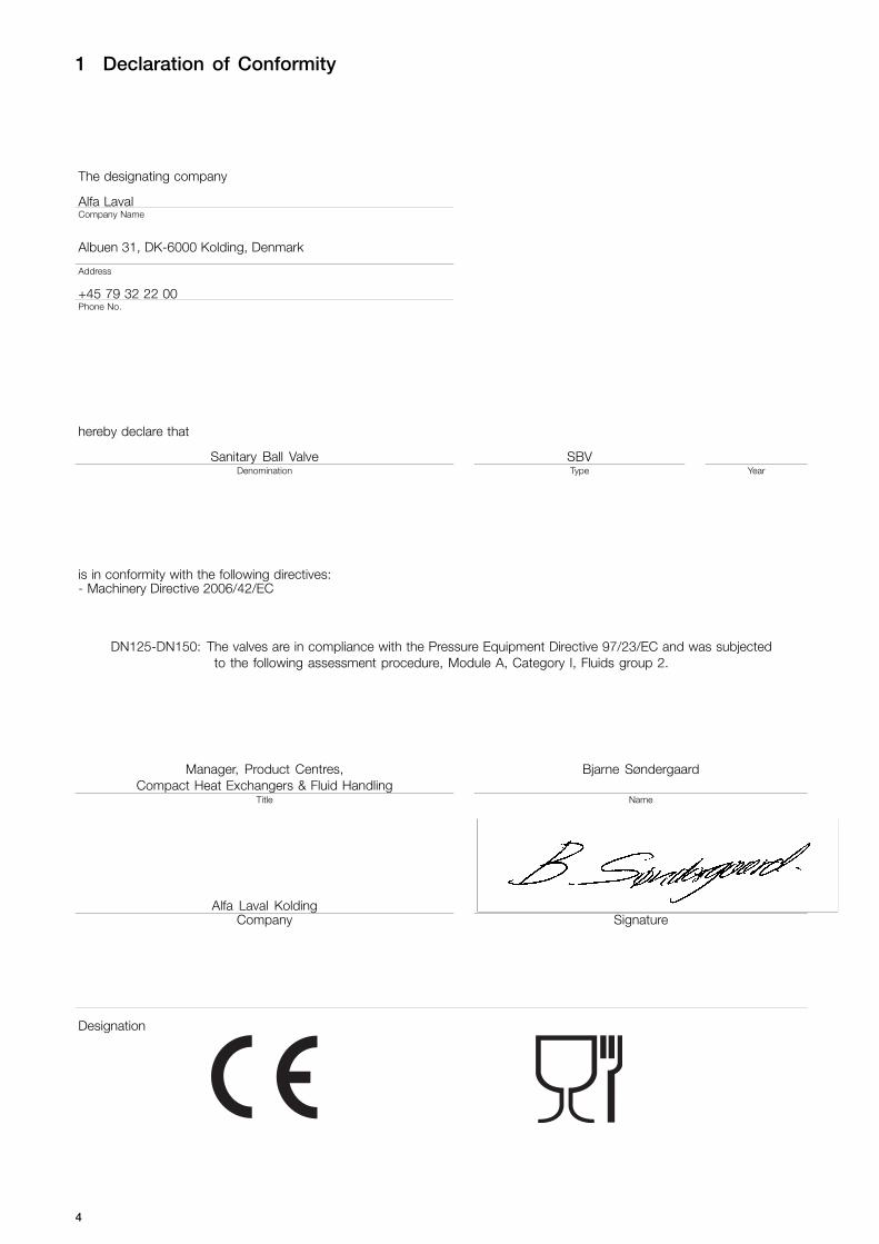
1 Declaration of Conformity
The designating company
Alfa LavalCompany Name
Albuen 31, DK-6000 Kolding, Denmark
Address
+45 79 32 22 00Phone No.
hereby declare that
Sanitary Ball Valve SBVDenomination Type Year
is in conformity with the following directives:- Machinery Directive 2006/42/EC
DN125-DN150: The valves are in compliance with the Pressure Equipment Directive 97/23/EC and was subjectedto the following assessment procedure, Module A, Category I, Fluids group 2.
Manager, Product Centres,Compact Heat Exchangers & Fluid Handling
Bjarne Søndergaard
Title Name
Alfa Laval KoldingCompany Signature
Designation
4
2 Safety
Unsafe practices and other important information are emphasized in this manual.Warnings are emphasized by means of special signs.
2.1 Important information
Always read the manual before using the valve!
WARNINGIndicates that special procedures must be followed to avoid severe personal injury.
CAUTIONIndicates that special procedures must be followed to avoid damage to the valve.
NOTEIndicates important information to simplify or clarify procedures.
2.2 Warning signs
General warning:
Caustic agents:
5
2 Safety
All warnings in the manual are summarized on this page.Pay special attention to the instructions below so that severe personal injury and/or damage to the valve are avoided.
2.3 Safety precautions
Installation:
Always observe the technical data (See chapter 6 Technical data)Always release compressed air after use.
Operation:
Always observe the technical data (See chapter 6 Technical data)Never touch the valve or the pipelines when processing hot liquids or when sterilizing
Always handle lye and acid with great care
Maintenance:
- Always observe the technical data (See chapter 6 Technical data)- Always release compressed air after use- The valve must Never be hot when servicing it- The valve/actuator and the pipelines must never be pressurised when servicing the valve/ actuator- Never stick your fingers through the valve ports if the valve is supplied with compressed air.
Transportation:
Always secure that compressed air is releasedAlways secure that all connections is disconnected before attemt to remove the valve from the installationAlways drain liquid out of valves before transportationAlways used predesigned lifting points if definedAlways secure sufficient fixing of the valve during transportation - if special designed packaging material is available itmust be used
6
3 Installation
The instruction manual is part of the delivery.Study the instructions carefully.The items refer to parts list and service kits section.
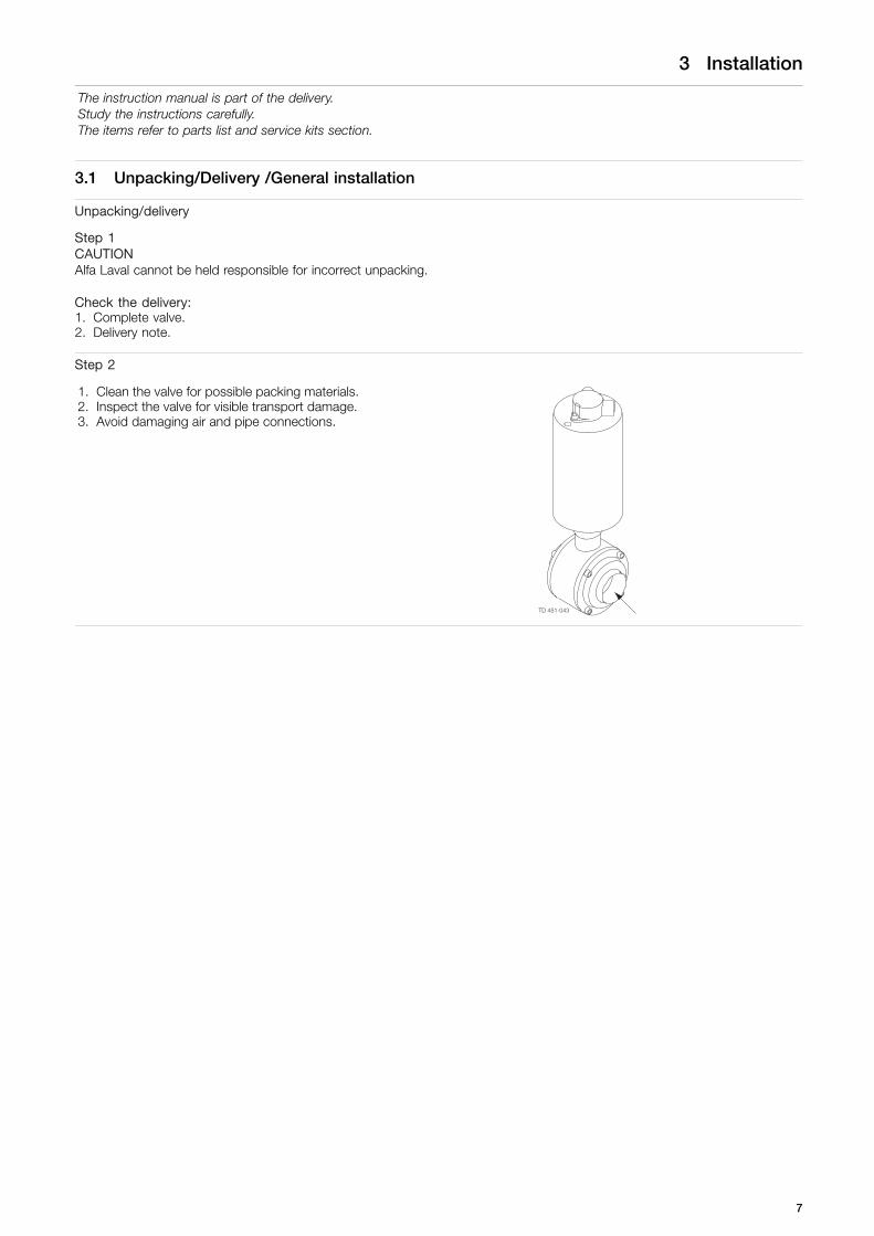
3.1 Unpacking/Delivery /General installation
Unpacking/delivery
Step 1CAUTIONAlfa Laval cannot be held responsible for incorrect unpacking.
Check the delivery:1. Complete valve.2. Delivery note.
Step 2
1. Clean the valve for possible packing materials.2. Inspect the valve for visible transport damage.3. Avoid damaging air and pipe connections.
7
3 Installation
The instruction manual is part of the delivery.Study the instructions carefully.The items refer to parts list and service kits section.
3.2 General installation
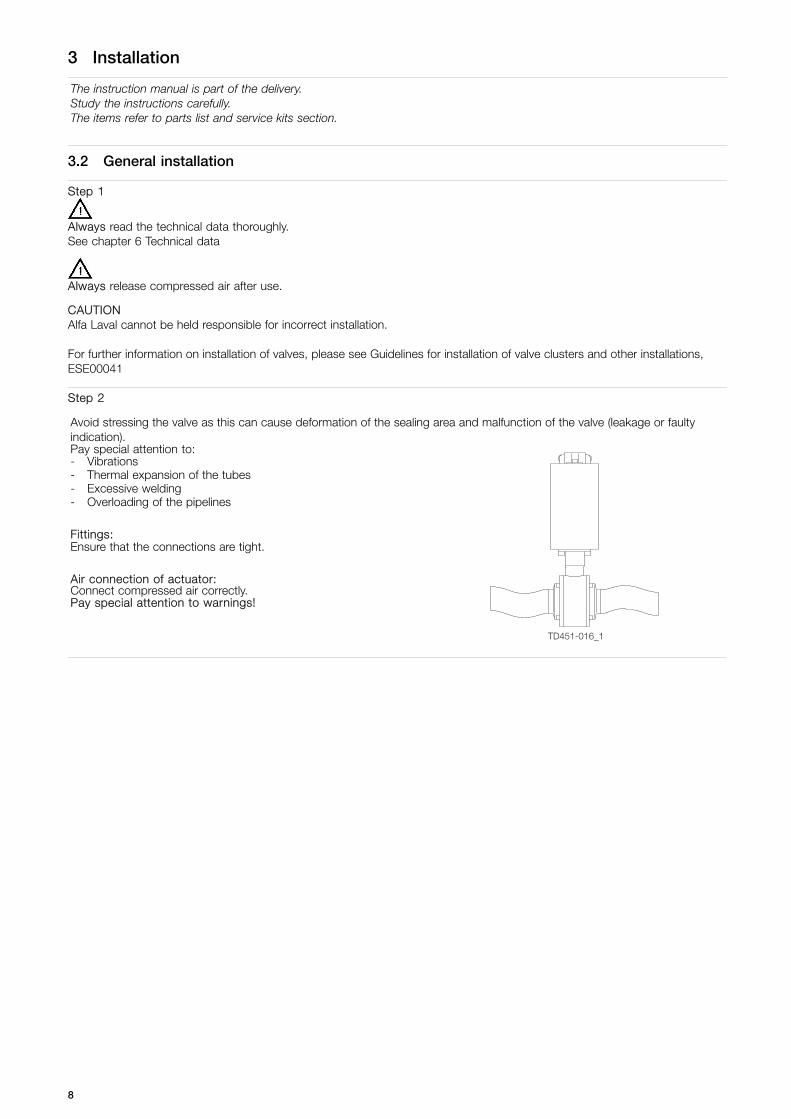
Step 1
Always read the technical data thoroughly.See chapter 6 Technical data
Always release compressed air after use.
CAUTIONAlfa Laval cannot be held responsible for incorrect installation.
For further information on installation of valves, please see Guidelines for installation of valve clusters and other installations,ESE00041
Step 2
Avoid stressing the valve as this can cause deformation of the sealing area and malfunction of the valve (leakage or faultyindication).Pay special attention to:- Vibrations- Thermal expansion of the tubes- Excessive welding- Overloading of the pipelines
Fittings:Ensure that the connections are tight.
Air connection of actuator:Connect compressed air correctly.Pay special attention to warnings!
TD451-016_1
8
3 Installation
Study the instructions carefully.
3.3 Welding
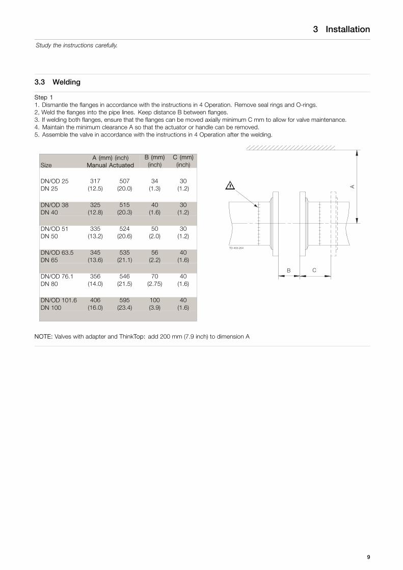
Step 11. Dismantle the flanges in accordance with the instructions in 4 Operation. Remove seal rings and O-rings.2, Weld the flanges into the pipe lines. Keep distance B between flanges.3. If welding both flanges, ensure that the flanges can be moved axially minimum C mm to allow for valve maintenance.4. Maintain the minimum clearance A so that the actuator or handle can be removed.5. Assemble the valve in accordance with the instructions in 4 Operation after the welding.
SizeA (mm) (inch)
Manual ActuatedB (mm)(inch)
C (mm)(inch)
DN/OD 25DN 25
317(12.5)
507(20.0)
34(1.3)
30(1.2)
DN/OD 38DN 40
325(12.8)
515(20.3)
40(1.6)
30(1.2)
DN/OD 51DN 50
335(13.2)
524(20.6)
50(2.0)
30(1.2)
DN/OD 63.5DN 65
345(13.6)
535(21.1)
56(2.2)
40(1.6)
DN/OD 76.1DN 80
356(14.0)
546(21.5)
70(2.75)
40(1.6)
DN/OD 101.6DN 100
406(16.0)
595(23.4)
100(3.9)
40(1.6)
NOTE: Valves with adapter and ThinkTop: add 200 mm (7.9 inch) to dimension A
9

3 Installation
Study the instructions carefully.
Step 2Pre-use check:
Open and close the valve several times to ensure that the ball moves smoothly against the seal rings.
Pay special attention to the warnings!
3.4 Indication and control equipment (optional extras)
CAUTION!The indication and control equipment must be electrically installed by authorized personnel only.- Inductive proximity switches:
(See the instructions on the unit).- ThinkTop®:
(See the separate instruction manual).
Manual valves:Manual valves with optional handle for inductive proximity switches aredesigned for the mounting of one or two M12 feedback sensors for openand/or closed position detection. Feedback sensors should be installed andadjusted according to the specification on the unit.
Valves with standard actuator:Valves with standard actuator are prepared for the mounting of one or twoM12 feedback sensors on the position indicator.
10
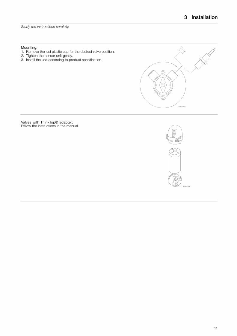
3 Installation
Study the instructions carefully.
Mounting:1. Remove the red plastic cap for the desired valve position.2. Tighten the sensor unit gently.3. Install the unit according to product specification.
Valves with ThinkTop® adapter:Follow the instructions in the manual.
11
4 Operation
Study the instructions carefully and pay special attention to the warnings!The valve is automatically or manually operated by means of an actuator or a handle.
4.1 Operation
Step 1
Always read the technical data thoroughly.(see chapter 6 Technical data)
CAUTIONAlfa Laval cannot be held responsible for incorrect operation.
Step 2
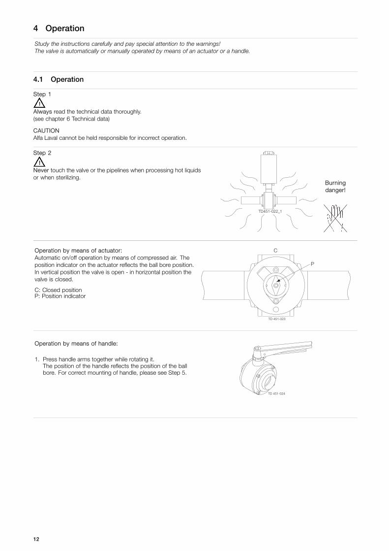
Never touch the valve or the pipelines when processing hot liquidsor when sterilizing.
Burningdanger!
TD451-022_1
Operation by means of actuator:Automatic on/off operation by means of compressed air. Theposition indicator on the actuator reflects the ball bore position.In vertical position the valve is open - in horizontal position thevalve is closed.
C: Closed positionP: Position indicator
Operation by means of handle:
1. Press handle arms together while rotating it.The position of the handle reflects the position of the ballbore. For correct mounting of handle, please see Step 5.
12
4 Operation
Pay attention to possible break-down.Study the instructions carefully.NC = Normally closed.NO = Normally open.
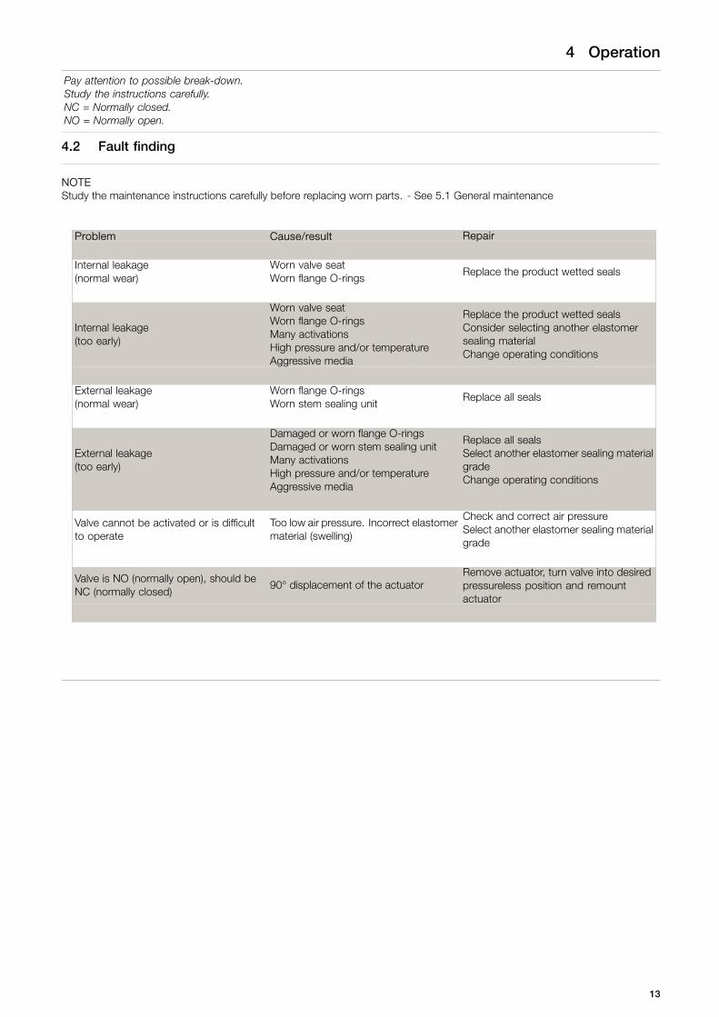
4.2 Fault finding
NOTEStudy the maintenance instructions carefully before replacing worn parts. - See 5.1 General maintenance
Problem Cause/result Repair
Internal leakage(normal wear)
Worn valve seatWorn flange O-rings
Replace the product wetted seals
Internal leakage(too early)
Worn valve seatWorn flange O-ringsMany activationsHigh pressure and/or temperatureAggressive media
Replace the product wetted sealsConsider selecting another elastomersealing materialChange operating conditions
External leakage(normal wear)
Worn flange O-ringsWorn stem sealing unit
Replace all seals
External leakage(too early)
Damaged or worn flange O-ringsDamaged or worn stem sealing unitMany activationsHigh pressure and/or temperatureAggressive media
Replace all sealsSelect another elastomer sealing materialgradeChange operating conditions
Valve cannot be activated or is difficultto operate
Too low air pressure. Incorrect elastomermaterial (swelling)
Check and correct air pressureSelect another elastomer sealing materialgrade
Valve is NO (normally open), should beNC (normally closed)
90° displacement of the actuatorRemove actuator, turn valve into desiredpressureless position and remountactuator
13
4 Operation
The valve is designed for cleaning in place (CIP). CIP = Cleaning In Place.Study the instructions carefully and pay special attention to the warnings!NaOH = Caustic Soda.HNO3= Nitric acid.
4.3 Recommended cleaning
Step 1
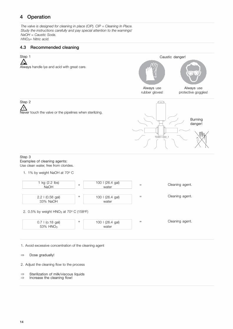
Always handle lye and acid with great care.
Caustic danger!
Always userubber gloves!
Always useprotective goggles!
Step 2
Never touch the valve or the pipelines when sterilizing.
Burningdanger!
TD451-022_1
Step 3Examples of cleaning agents:Use clean water, free from clorides.
1. 1% by weight NaOH at 70o C
1 kg (2.2 lbs)NaOH
+ 100 l (26.4 gal)water
= Cleaning agent.
+ = Cleaning agent.2.2 l (0.58 gal)33% NaOH
100 l (26.4 gal)water
2. 0.5% by weight HNO3 at 70o C (158oF)
+ = Cleaning agent.0.7 l (o.18 gal)53% HNO3
100 l (26.4 gal)water
1. Avoid excessive concentration of the cleaning agent
⇒ Dose gradually!
2. Adjust the cleaning flow to the process
⇒ Sterilization of milk/viscous liquids⇒ Increase the cleaning flow!
14
4 Operation
The valve is designed for cleaning in place (CIP). CIP = Cleaning In Place.Study the instructions carefully and pay special attention to the warnings!NaOH = Caustic Soda.HNO3= Nitric acid.
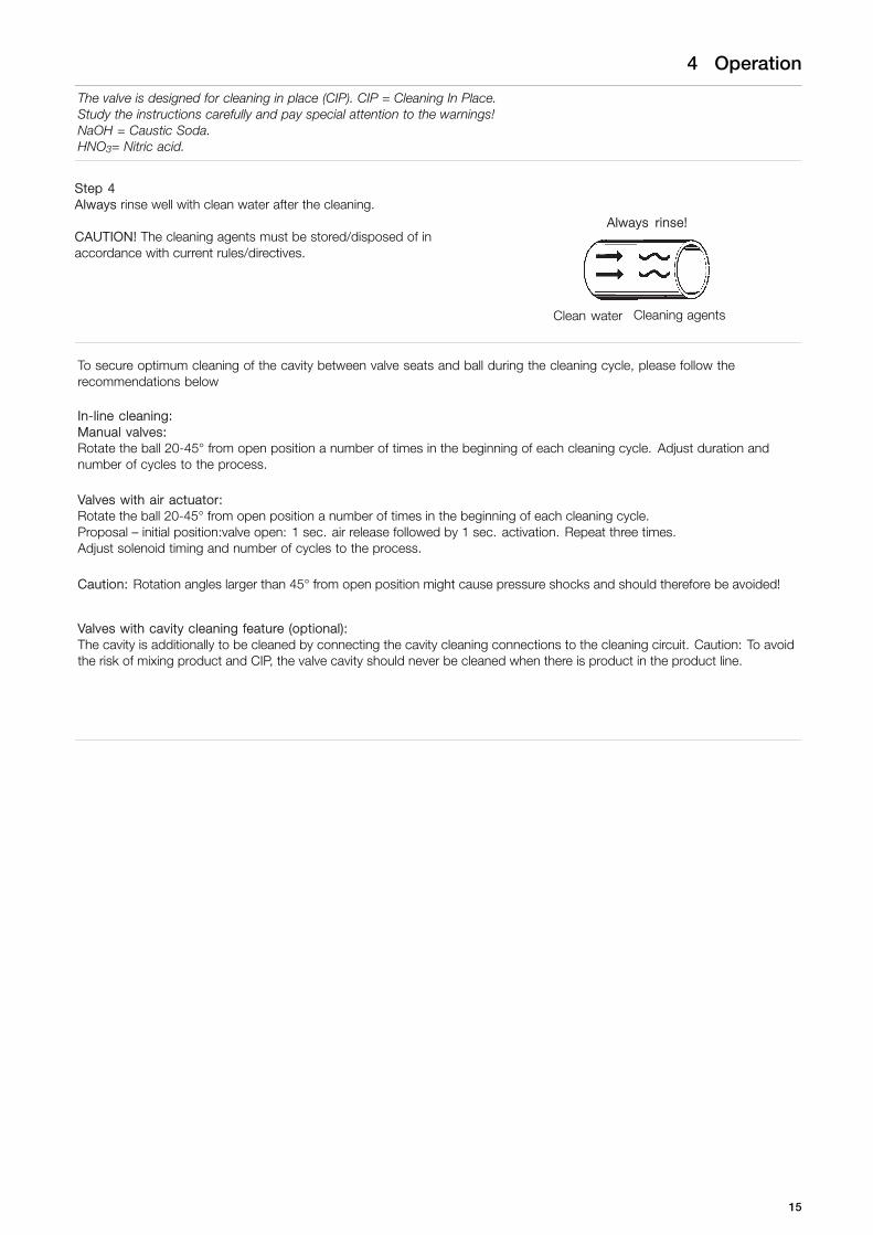
Step 4Always rinse well with clean water after the cleaning.
CAUTION! The cleaning agents must be stored/disposed of inaccordance with current rules/directives.
Always rinse!
Clean water Cleaning agents
To secure optimum cleaning of the cavity between valve seats and ball during the cleaning cycle, please follow therecommendations below
In-line cleaning:Manual valves:Rotate the ball 20-45° from open position a number of times in the beginning of each cleaning cycle. Adjust duration andnumber of cycles to the process.
Valves with air actuator:Rotate the ball 20-45° from open position a number of times in the beginning of each cleaning cycle.Proposal – initial position:valve open: 1 sec. air release followed by 1 sec. activation. Repeat three times.Adjust solenoid timing and number of cycles to the process.
Caution: Rotation angles larger than 45° from open position might cause pressure shocks and should therefore be avoided!
Valves with cavity cleaning feature (optional):The cavity is additionally to be cleaned by connecting the cavity cleaning connections to the cleaning circuit. Caution: To avoidthe risk of mixing product and CIP, the valve cavity should never be cleaned when there is product in the product line.
15
5 Maintenance
Maintain the valve and the actuator carefully.Study the instructions carefully and pay special attention to the warnings!Always keep service kits in stock.
5.1 General maintenance
Step 1
Always read the technical data thoroughly.See chapter 6 Technical data
Always release compressed air after use.
NOTEAll scrap must be stored/discharged in accordancewith current rules/directives.
Step 2
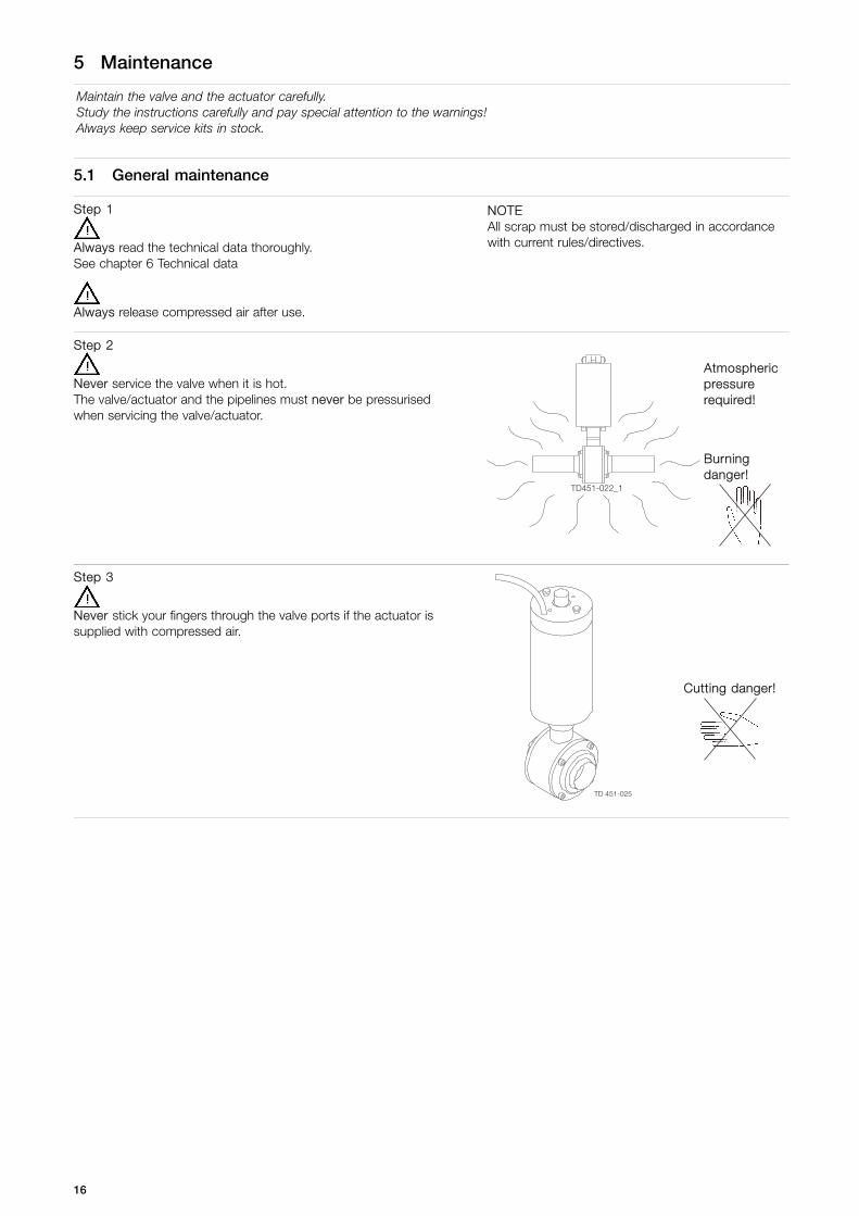
Never service the valve when it is hot.The valve/actuator and the pipelines must never be pressurisedwhen servicing the valve/actuator.
Atmosphericpressurerequired!
Burningdanger!
TD451-022_1
Step 3
Never stick your fingers through the valve ports if the actuator issupplied with compressed air.
Cutting danger!
16
5 Maintenance
Maintain the valve and the actuator carefully.Study the instructions carefully and pay special attention to the warnings!Always keep service kits in stock.
Recommended spare parts:Service kits (see chapter 6).Order service kits from the service kits list (see chapter 6).
Product wetted seals Valve stem seals
Preventive maintenance Replace after 12 months Replace all seals after 24 month
Maintenance after leakage(leakage normally starts slowly)
Replace at the end of the day Replace by the end of the day
Planned maintenance- Regular inspection for leakage
and smooth operation- Keep a record of the valve- Use the statistics for planning of
inspections
- Regular inspection for leakageand smooth operation
- Keep a record of the valve- Use the statistics for planning of
inspections
NOTE! The actuator is maintenance-free.
17
5 Maintenance
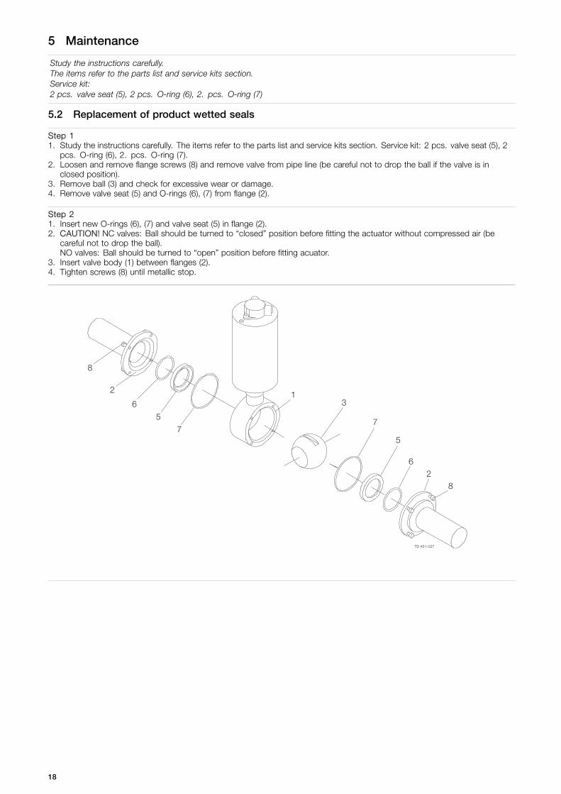
Study the instructions carefully.The items refer to the parts list and service kits section.Service kit:2 pcs. valve seat (5), 2 pcs. O-ring (6), 2. pcs. O-ring (7)
5.2 Replacement of product wetted seals
Step 11. Study the instructions carefully. The items refer to the parts list and service kits section. Service kit: 2 pcs. valve seat (5), 2
pcs. O-ring (6), 2. pcs. O-ring (7).2. Loosen and remove flange screws (8) and remove valve from pipe line (be careful not to drop the ball if the valve is in
closed position).3. Remove ball (3) and check for excessive wear or damage.4. Remove valve seat (5) and O-rings (6), (7) from flange (2).
Step 21. Insert new O-rings (6), (7) and valve seat (5) in flange (2).2. CAUTION! NC valves: Ball should be turned to “closed” position before fitting the actuator without compressed air (be
careful not to drop the ball).NO valves: Ball should be turned to “open” position before fitting acuator.
3. Insert valve body (1) between flanges (2).4. Tighten screws (8) until metallic stop.
18
5 Maintenance
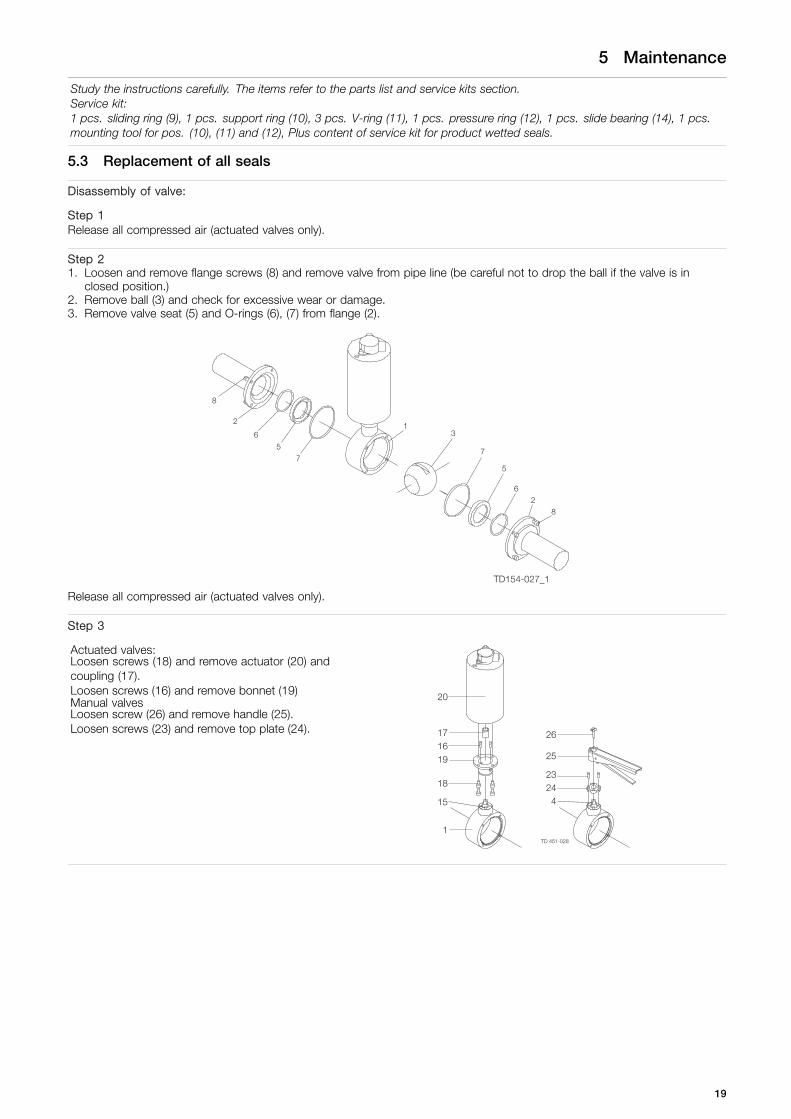
Study the instructions carefully. The items refer to the parts list and service kits section.Service kit:1 pcs. sliding ring (9), 1 pcs. support ring (10), 3 pcs. V-ring (11), 1 pcs. pressure ring (12), 1 pcs. slide bearing (14), 1 pcs.mounting tool for pos. (10), (11) and (12), Plus content of service kit for product wetted seals.
5.3 Replacement of all seals
Disassembly of valve:
Step 1Release all compressed air (actuated valves only).
Step 21. Loosen and remove flange screws (8) and remove valve from pipe line (be careful not to drop the ball if the valve is in
closed position.)2. Remove ball (3) and check for excessive wear or damage.3. Remove valve seat (5) and O-rings (6), (7) from flange (2).
TD154-027_1
Release all compressed air (actuated valves only).
Step 3
Actuated valves:Loosen screws (18) and remove actuator (20) andcoupling (17).Loosen screws (16) and remove bonnet (19)Manual valvesLoosen screw (26) and remove handle (25).Loosen screws (23) and remove top plate (24).
19
5 Maintenance
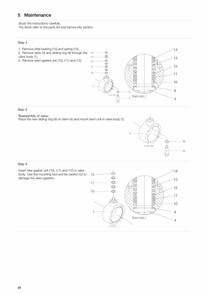
Study the instructions carefully.The items refer to the parts list and service kits section.
Step 4
1. Remove slide bearing (14) and spring (13).2. Remove stem (4) and sliding ring (9) through thevalve body (1).3. Remove stem gasket unit (10), (11) and (12).
TD451-002_1
14
13
12
11
10
9
4
Step 5
Reassembly of valve:Place the new sliding ring (9) on stem (4) and mount stem unit in valve body (1)
Step 6
Insert new gasket unit (10), (11) and (12) in valvebody. Use the mounting tool and be careful not todamage the stem gaskets.
TD451-002_1
14
13
12
11
10
9
4
20
5 Maintenance
Study the instructions carefully.The items refer to the parts list and service kits section.
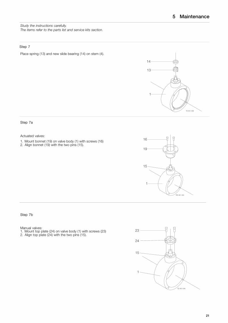
Step 7
Place spring (13) and new slide bearing (14) on stem (4).
TD 451-032
Step 7a
Actuated valves:
1. Mount bonnet (19) on valve body (1) with screws (16)2. Align bonnet (19) with the two pins (15).
Step 7b
Manual valves:1. Mount top plate (24) on valve body (1) with screws (23)2. Align top plate (24) with the two pins (15).
21
5 Maintenance
Study the instructions carefully.The items refer to the parts list and service kits section.
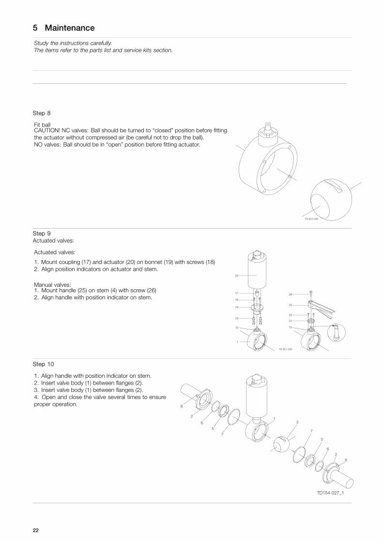
Step 8
Fit ballCAUTION! NC valves: Ball should be turned to “closed” position before fittingthe actuator without compressed air (be careful not to drop the ball).NO valves: Ball should be in “open” position before fitting actuator.
Step 9Actuated valves:
Actuated valves:
1. Mount coupling (17) and actuator (20) on bonnet (19) with screws (18)2. Align position indicators on actuator and stem.
Manual valves:1. Mount handle (25) on stem (4) with screw (26)2. Align handle with position indicator on stem.
Step 10
1. Align handle with position indicator on stem.2. Insert valve body (1) between flanges (2).3. Insert valve body (1) between flanges (2).4. Open and close the valve several times to ensureproper operation.
TD154-027_1
22
6 Technical data
It is important to observe the technical data during installation, operation and maintenance.Inform the personnel about the technical data.NC = Normally closed.NO = Normally open.
6.1 Technical data
Valve
Max. product pressure 1600 kPa (10 bar) (232 PSI)Max. recommended pressure during activation 600 kPa (6 bar)Min. product pressure Full vacuumTemperature range -10o C to + 130o C (14oto 266° F) (EPDM).Air consumption ø104: 0.5 Nl Air consumption ø104: 0.5 NlAir consumption ø129: 0.75 Nl Air consumption ø129: 0.75 NlMax. sterilisation temperature, short time + 150° C (302° F)
Actuator
Operating pressure 600 - 1000 kPa (6 - 10 bar) (87 - 145 PSI)Temperature range +4° C to +60° C (39.2 to 140 F)
Materials
Product wetted steel parts AISI 316LOther steel parts AISI 304Surface quality, product wetted parts Ra < 0.8μmExternal surface finish Semi brightExternal surface finish, actuator Semi bright (brushed)Product wetted seals PTFE, EPDMOther seals PTFE, NBR
NoiseOne meter away from - and 1.6 meter above the exhaust the noise level of a valve actuator will be approximately 77db(A)without noise damper and approximately 72 db (A) with damper - Measured at 7 bars air-pressure.
Recycling information.Unpacking- Packing material consists of wood, plastics, cardboard boxes and in some cases metal straps.- Wood and cardboard boxes can be reused, recycled or used for energy recovery.- Plastics should be recycled or burnt at a licensed waste incineration plant.- Metal straps should be sent for material recycling.
Maintenance- During maintenance oil and wear parts in the machine are replaced.- All metal should be sent for material recycling.- Worn out or defective electronic parts should be sent to a licensed handler for material recycling.- Oil and all non metal wear parts must be taken care of in agreement with local regulations.
Scrapping- At end of use, the equipment shall be recycled according to relevant, local regulations. Beside the equipment itself, any
hazardous residues from the process liquid must be considered and death with in a proper manner. When in doubt, or inthe absence of local regulations, please contact the local Alfa Laval sales company.
23

6 Technical data
It is important to observe the technical data during installation, operation and maintenance.Inform the personnel about the technical data.NC = Normally closed.NO = Normally open.
7.1 SBV Satary Ball Valve
24
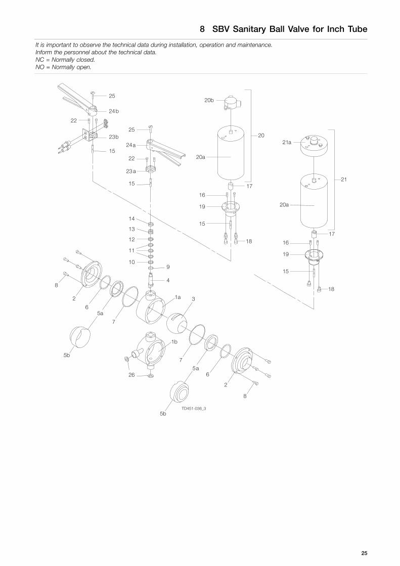
8 SBV Sanitary Ball Valve for Inch Tube
It is important to observe the technical data during installation, operation and maintenance.Inform the personnel about the technical data.NC = Normally closed.NO = Normally open.
1a
1b
TD451-036_3
25

8 SBV Sanitary Ball Valve for Inch Tube
It is important to observe the technical data during installation, operation and maintenance.Inform the personnel about the technical data.NC = Normally closed.NO = Normally open.
Parts list
Pos. Qty Denomination
Product with parts♦ All seals
Product with parts with caveryfillersAll seals with cavery fillers
1a 1 Valve body2 2 Flange3 1 Ball4 1 Stem5a ♦ 2 Valve seat5b 2 Valve seat6 ♦ 2 O-ring7 ♦ 2 O-ring8 8 Flange9 ♦ 1 Sliding ring10 ♦ 1 Support ring11 ♦ 3 V-rings12 ♦ 1 Pressure ring13 1 Spring14 ♦ 1 Slide bearing15 2 Pin16 2 Screw (act.)17 1 Coupling18 2 Screw19 1 Bonnet20 1 Actuator complete, standard
version20a Actuator20b 1 Position indicator complete21 Actuator complete, ThinkTop
version21a 1 ThinkTop adapter complete22 2 Screw (man.)23a 1 Top plate23b Top plate24a 1 Handle24b Handle25 1 Screw26 2 Seal for valves with cavity cleaning
connections **
Service kits
Denomination DN25 DN38 DN51 DN63.5 DN76.1 DN101.6
Service Kits for Product wetted parts
Service kit, EPDM (std.) . . . . 9612-64-7701 9612-64-7709 9612-64-7717 9612-64-7725 9612-64-7733 9612-64-7741
Service kit, H-NBR . . . . . . . . . 9612-64-7702 9612-64-7710 9612-64-7718 9612-64-7726 9612-64-7734 9612-64-7742
Service kit, Q . . . . . . . . . . . . . . . 9612-64-7703 9612-64-7711 9612-64-7719 9612-64-7727 9612-64-7735 9612-64-7743
Service kit, FPM . . . . . . . . . . . . 9612-64-7704 9612-64-7712 9612-64-7720 9612-64-7728 9612-64-7736 9612-64-7744
Service Kits for Cavity fillers
Service kit, EPDM (std.) . . . . 9612-64-7801 9612-64-7809 9612-64-7817 9612-64-7825 9612-64-7833 9612-64-7841
Service kit, H-NBR . . . . . . . . . 9612-64-7802 9612-64-7810 9612-64-7818 9612-64-7826 9612-64-7834 9612-64-7842
Service kit, Q . . . . . . . . . . . . . . . 9612-64-7803 9612-64-7811 9612-64-7819 9612-64-7827 9612-64-7835 9612-64-7843
Service kit, FPM . . . . . . . . . . . . 9612-64-7804 9612-64-7812 9612-64-7820 9612-64-7828 9612-64-7836 9612-64-7844
Service kits
Denomination DN25 DN38 DN51 DN63.5 DN76.1 DN101.6
Service Kits for All seals♦ Service kit, EPDM (std.) * . . 9612-64-7705 9612-64-7713 9612-64-7721 9612-64-7729 9612-64-7737 9612-64-7745
26
8 SBV Sanitary Ball Valve for Inch Tube
It is important to observe the technical data during installation, operation and maintenance.Inform the personnel about the technical data.NC = Normally closed.NO = Normally open.
♦ Service kit, H-NBR * . . . . . . . 9612-64-7706 9612-64-7714 9612-64-7722 9612-64-7730 9612-64-7738 9612-64-7746♦ Service kit, Q * . . . . . . . . . . . . . 9612-64-7707 9612-64-7715 9612-64-7723 9612-64-7731 9612-64-7739 9612-64-7747♦ Service kit, FPM * . . . . . . . . . . 9612-64-7708 9612-64-7716 9612-64-7724 9612-64-7732 9612-64-7740 9612-64-7748
Service Kits for Cavity fillers
Service kit, EPDM (std.) * . . 9612-64-7805 9612-64-7813 9612-64-7821 9612-64-7829 9612-64-7837 9612-64-7845
Service kit, H-NBR * . . . . . . . 9612-64-7806 9612-64-7814 9612-64-7822 9612-64-7830 9612-64-7838 9612-64-7846
Service kit, Q * . . . . . . . . . . . . . 9612-64-7807 9612-64-7815 9612-64-7823 9612-64-7831 9612-64-7839 9612-64-7847
Service kit, FPM * . . . . . . . . . . 9612-64-7808 9612-64-7816 9612-64-7824 9612-64-7832 9612-64-7840 9612-64-7848
* Including mounting tool for stem gasket unit** Not included in service kits
Parts marked with ♦ are included in the service kits.
Recommended spare parts: Service kits.
900152/1
27
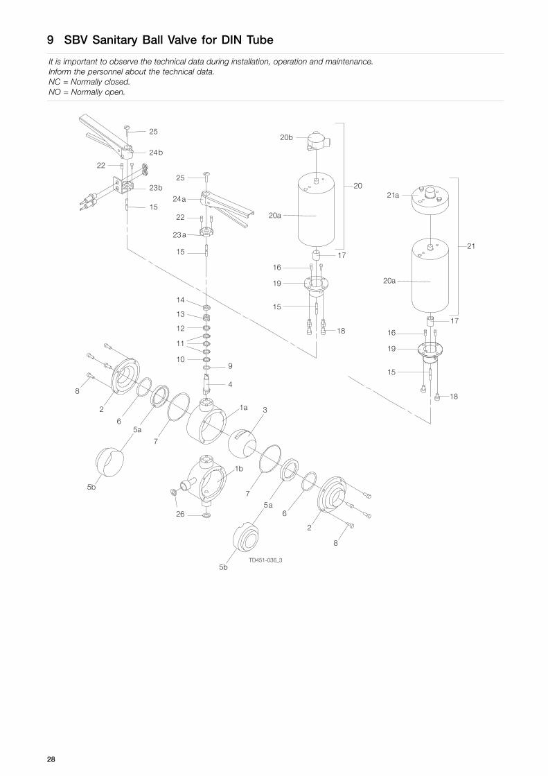
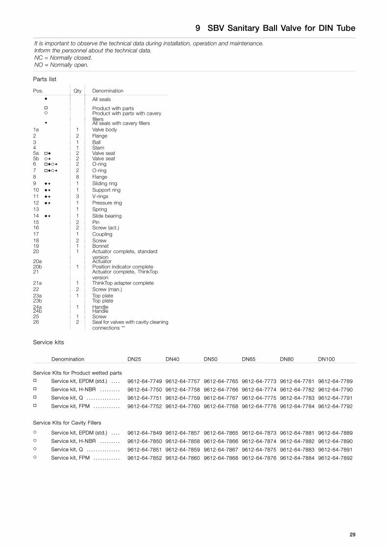
9 SBV Sanitary Ball Valve for DIN Tube
It is important to observe the technical data during installation, operation and maintenance.Inform the personnel about the technical data.NC = Normally closed.NO = Normally open.
1a
1b
TD451-036_3
28
9 SBV Sanitary Ball Valve for DIN Tube
It is important to observe the technical data during installation, operation and maintenance.Inform the personnel about the technical data.NC = Normally closed.NO = Normally open.
Parts list
Pos. Qty Denomination
♦ All seals
Product with partsProduct with parts with caveryfillersAll seals with cavery fillers
1a 1 Valve body2 2 Flange3 1 Ball4 1 Stem5a ♦ 2 Valve seat5b 2 Valve seat6 ♦ 2 O-ring7 ♦ 2 O-ring8 8 Flange9 ♦ 1 Sliding ring10 ♦ 1 Support ring11 ♦ 3 V-rings12 ♦ 1 Pressure ring13 1 Spring14 ♦ 1 Slide bearing15 2 Pin16 2 Screw (act.)17 1 Coupling18 2 Screw19 1 Bonnet20 1 Actuator complete, standard
version20a Actuator20b 1 Position indicator complete21 Actuator complete, ThinkTop
version21a 1 ThinkTop adapter complete22 2 Screw (man.)23a 1 Top plate23b Top plate24a 1 Handle24b Handle25 1 Screw26 2 Seal for valves with cavity cleaning
connections **
Service kits
Denomination DN25 DN40 DN50 DN65 DN80 DN100
Service Kits for Product wetted parts
Service kit, EPDM (std.) . . . . 9612-64-7749 9612-64-7757 9612-64-7765 9612-64-7773 9612-64-7781 9612-64-7789
Service kit, H-NBR . . . . . . . . . 9612-64-7750 9612-64-7758 9612-64-7766 9612-64-7774 9612-64-7782 9612-64-7790
Service kit, Q . . . . . . . . . . . . . . . 9612-64-7751 9612-64-7759 9612-64-7767 9612-64-7775 9612-64-7783 9612-64-7791
Service kit, FPM . . . . . . . . . . . . 9612-64-7752 9612-64-7760 9612-64-7768 9612-64-7776 9612-64-7784 9612-64-7792
Service Kits for Cavity Fillers
Service kit, EPDM (std.) . . . . 9612-64-7849 9612-64-7857 9612-64-7865 9612-64-7873 9612-64-7881 9612-64-7889
Service kit, H-NBR . . . . . . . . . 9612-64-7850 9612-64-7858 9612-64-7866 9612-64-7874 9612-64-7882 9612-64-7890
Service kit, Q . . . . . . . . . . . . . . . 9612-64-7851 9612-64-7859 9612-64-7867 9612-64-7875 9612-64-7883 9612-64-7891
Service kit, FPM . . . . . . . . . . . . 9612-64-7852 9612-64-7860 9612-64-7868 9612-64-7876 9612-64-7884 9612-64-7892
29
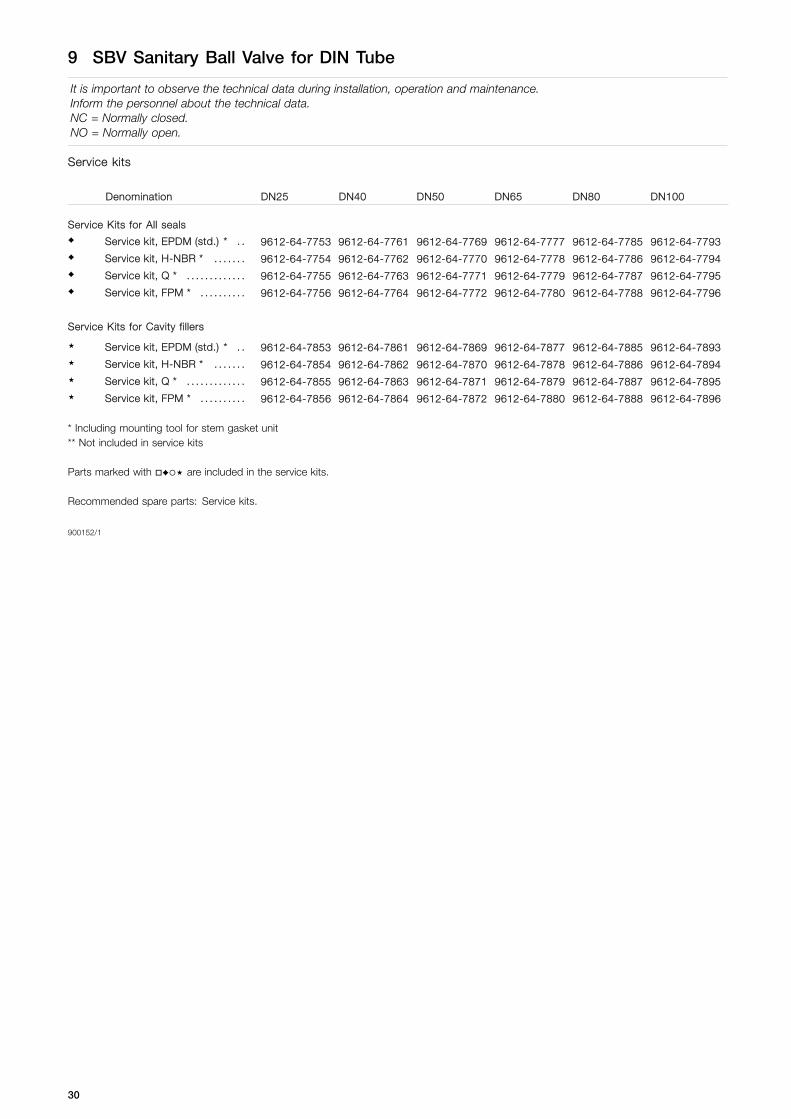
9 SBV Sanitary Ball Valve for DIN Tube
It is important to observe the technical data during installation, operation and maintenance.Inform the personnel about the technical data.NC = Normally closed.NO = Normally open.
Service kits
Denomination DN25 DN40 DN50 DN65 DN80 DN100
Service Kits for All seals♦ Service kit, EPDM (std.) * . . 9612-64-7753 9612-64-7761 9612-64-7769 9612-64-7777 9612-64-7785 9612-64-7793♦ Service kit, H-NBR * . . . . . . . 9612-64-7754 9612-64-7762 9612-64-7770 9612-64-7778 9612-64-7786 9612-64-7794♦ Service kit, Q * . . . . . . . . . . . . . 9612-64-7755 9612-64-7763 9612-64-7771 9612-64-7779 9612-64-7787 9612-64-7795♦ Service kit, FPM * . . . . . . . . . . 9612-64-7756 9612-64-7764 9612-64-7772 9612-64-7780 9612-64-7788 9612-64-7796
Service Kits for Cavity fillers
Service kit, EPDM (std.) * . . 9612-64-7853 9612-64-7861 9612-64-7869 9612-64-7877 9612-64-7885 9612-64-7893
Service kit, H-NBR * . . . . . . . 9612-64-7854 9612-64-7862 9612-64-7870 9612-64-7878 9612-64-7886 9612-64-7894
Service kit, Q * . . . . . . . . . . . . . 9612-64-7855 9612-64-7863 9612-64-7871 9612-64-7879 9612-64-7887 9612-64-7895
Service kit, FPM * . . . . . . . . . . 9612-64-7856 9612-64-7864 9612-64-7872 9612-64-7880 9612-64-7888 9612-64-7896
* Including mounting tool for stem gasket unit** Not included in service kits
Parts marked with ♦ are included in the service kits.
Recommended spare parts: Service kits.
900152/1
30

31

How to contact Alfa LavalContact details for all countries arecontinually updated on our website.Please visit www.alfalaval.com to access the information direct.
© Alfa Laval Corporate ABThis document and its contents is owned by Alfa Laval Corporate AB and protected by laws governing intellectual property and thereto related rights. It is the responsibility of the user of thisdocument to comply with all applicable intellectual property laws. Without limiting any rights related to this document, no part of this document may be copied, reproduced or transmitted in anyform or by any means (electronic, mechanical, photocopying, recording, or otherwise), or for any purpose, without the expressed permission of Alfa Laval Corporate AB. Alfa Laval Corporate ABwill enforce its rights related to this document to the fullest extent of the law, including the seeking of criminal prosecution.