Embed Size (px)
Citation preview

ALI MAZHAR OPTIMIZATION OF HSDPA IN INDOOR ENVIRONMENT WITH REPEATER AND DISTRIBUTED ANTENNA SYSTEMS MASTER OF SCIENCE THESIS
Examiners: Professor Jukka Lempiäinen M.Sc. Tero Isotalo Examiners and topic approved in the Information Technology Department Council meeting on 2nd June 2010

II
PREFACE In the name of Allah the most gracious, the most merciful! This Master of Science Thesis “Optimization of HSDPA in Indoor Environment with Repeater and Distributed Antenna Systems” is based on the research work conducted during my studies at the Institute of Communications Engineering at Tampere University of Technology, Finland. I would like to express my sincere gratitude to Prof. Jukka Lempiäinen for providing me with the opportunity to carry out this work. I would also like to acknowledge my research supervisor Tero Isotalo for his valuable guidance, co-operative supervision and patience during my work. Special thanks goes to my colleagues from Radio Network Group; Jussi Turkka, Usman Sheikh and Panu Lähdekorpi for their useful discussions and tremendous support even during holidays. My divine and heartiest thanks go to my parents Mazhar and Farida; my sisters Asma, Sana and Izna and, last but not the least, my dear wife Quratulain for; without their support, encouragement, endless love, countless prayers and patience, all this would not have been possible. Tampere, May 24th, 2010 Ali Mazhar [email protected] Tel: +358504810238

III
ABSTRACT TAMPERE UNIVERSITY OF TECHNOLOGY Master’s Degree Programme in Information Technology MAZHAR, ALI : Optimization of HSDPA in Indoor Environment with Repeater and Distributed Antenna Systems Master of Science Thesis, 70 pages, 1 Appendix page June 2010 Major: Communications Engineering Examiners: Professor Jukka Lempiäinen and M.Sc. Tero Isotalo Keywords: HSDPA, Radio Network Planning, WCDMA Repeater, Indoor Planning Over the last decade, mobile communication networks have evolved tremendously with key focus on providing high speed data services in addition to voice. The third generation of mobile networks in the form of UMTS is already offering revolutionary mobile broadband experience to its users by deploying HSDPA as its packet-data technology. With data speeds up to 14.4 Mbps and ubiquitous mobility, HSDPA is anticipated to become a preferred broadband access medium for end-users via mobile phones, laptops etc. While majority of these end-users are located indoors most of the times, approximately 70-80% of the HSDPA traffic is estimated to originate from inside the buildings. Thus for network operators, indoor coverage has become a necessity for technical and business reasons.
Macro-cellular (outdoor) to indoor coverage is a natural inexpensive way of providing network coverage inside the buildings. However, it does not guarantee sufficient link quality required for optimal HSDPA operation. On the contrary, deploying a dedicated indoor system may be far too expensive from operator point of view. In this thesis, HSDPA performance improvement in typical indoor environments is studied by repeating outdoor signal to indoor distributed antenna systems via analogue WCDMA repeater. An extensive measurement campaign with varying network configurations was executed in different indoor environments analogous to easy, medium and hard radio conditions.
The results indicate how significant increase in HSDPA throughput can be achieved if outdoor-to-indoor signal strength is raised to an adequate level via repeater. Additionally, increasing the antenna density in distributed antenna system can further improve the network performance. Furthermore, it is shown that too high repeater gain settings and erroneous repeater installation can severely deteriorate network performance. Finally, the thesis attempts to provide indoor deployment guidelines for network planners by identifying optimal configurations related to repeater and distributed antenna system.

IV
TIIVISTELMÄ TAMPEREEN TEKNILLINEN YLIOPISTO Tietotekniikan koulutusohjelma MAZHAR, ALI : HSDPA:n toiminnan optimointi sisätiloissa toistimien ja hajautettujen antennijärjestelmien avulla Diplomityö, 70 sivua, 1 liitesivu Kesäkuu 2010 Pääaine: Tietoliikennetekniikka Tarkastaja: Professori Jukka Lempiäinen ja DI Tero Isotalo Avainsanat: HSDPA, Radio Network Planning, WCDMA Repeater, Indoor Planning Viimeisen vuosikymmenen aikana matkapuhelinverkot ovat kehittyneet suunnattomasti tavoitteenaan tarjota äänipuhelujen lisäksi suurinopeuksisia tietoliikennepalveluja. Kolmannen sukupolven UMTS matkapuhelinverkot tarjoavat jo vallankumouksellisen liikkuvan laajakaistan kokemuksen käyttäjilleen tarjoamalla HSDPA:n osana pakettidata teknologiaa. Jopa 14.4 Mbps nopeudella ja täydellisellä liikkuvuudella varustettuna HSDPA:n odotetaan tulevan pääasialliseksi laajakaistayhteydeksi matkapuhelinten ja kannettavien tietokoneiden ja muiden vastaavien laitteiden käyttäjille. Koska suurin osa loppukäyttäjistä on sisätiloissa suurimma osan ajasta, keskimäärin 70-80% HSDPA liikenteestä arvioidaan tulevan rakennusten sisältä. Siten sisätilojen peitto on tullut operaattoreille välttämättömäksi teknisistä ja kaupallisista syistä.
Ulkona sijaitsevien matkapuhelinmastojen peiton käyttö sisätiloissa on luonnollisesti edullinen tapa tarjota verkon peittoa rakennusten sisällä. Tämä tapa ei kuitenkaan tarjoa riittävää hyvälaatuista yhteyttä optimaaliseen HSDPA:n käyttöön. Toisaalta varta vasten sisätiloihin rakennettu järjestelmä saattaa olla operaattorin kannalta liian kallis ratkaisu. Tässä tutkielmassa HSDPA:n toimivuuden parantamista tyypillisessä sisätilassa on tutkittu toistamalla ulkoa tulevaa signaalia sisätiloissa toimivaan antennijärjestelmään analogisella WCDMA-toistimella.
Kattava mittauskampanja erilaisilla verkkokonfiguraatioilla suoritettiin erilaisissa sisätila ympäristöissä yhdenmukaisesti: hyvissä, keskinkertaisissa ja huonoissa radio-olosuhteissa. Tulokset osoittavat kuinka merkittävä lisäys HSDPA suorituskykyyn saadaan jos ulkotiloista sisätiloihin tulevan signaalin voimakkuutta kasvatetaan sopivalle tasolle toistimen avulla. Lisäksi antennien tiheyden lisääminen käytetyssä antennisysteemissä voi lisätä verkon suorituskykyä. Tämän lisäksi osoitetaan, että liian suuri vahvistus ja virheellinen toistimen asennus voivat vakavasti heikentää verkon suorituskykyä. Lopuksi tutkielmassa pyritään antamaan ohjeita verkon suunnittelijoille sisätilojen toteutuksen suunnittelussa esittämällä parhaat kokoonpanot liittyen toistimeen ja käytettyyn antennijärjestelmään.

V
TABLE OF CONTENTS 1. Introduction...............................................................................................................1 2. Introduction to UMTS/HSDPA ................................................................................3
2.1. Evolution and Standardization ..........................................................................3 2.2. UMTS Architecture...........................................................................................5 2.3. WCDMA for UMTS .........................................................................................6
2.3.1. Code Allocation ................................................................................9 2.3.2. UTRA Physical Layer: Channels and Signalling..............................9
2.4. Radio Resource Management .........................................................................10 2.5. High Speed Downlink Packet Access (HSDPA) ............................................11
2.5.1. HSDPA Technology .......................................................................11 2.5.2. Mobility and Handovers..................................................................17 2.5.3. HSDPA Performance ......................................................................18
3. Radio Propagation in UMTS...................................................................................19 3.1. Radio Channel and Signal Propagation...........................................................19
3.1.1. Propagation Slope ...........................................................................19 3.1.2. Multipath Propagation.....................................................................19 3.1.3. Fading..............................................................................................21 3.1.4. Propagation Models ........................................................................22
3.2. Propagation Environments..............................................................................22 3.2.1. Outdoor (Macro- and Micro-cell) ...................................................23 3.2.2. Indoor (Pico-cell) ............................................................................23 3.2.3. Indoor Propagation Channel ...........................................................23
4. UMTS Radio Network Planning.............................................................................26 4.1. Planning Process .............................................................................................26
4.1.1. Dimensioning ..................................................................................27 4.1.2. Detailed Planning............................................................................27 4.1.3. Optimization....................................................................................28
4.2. Topology Planning..........................................................................................28 4.2.1. Coverage Planning – Link Budget ..................................................30 4.2.2. Capacity Planning - Load Equations...............................................32
4.3. Indoor Coverage/Planning ..............................................................................34 4.3.1. Macro/Micro-cell Indoor Coverage ................................................34 4.3.2. Dedicated Indoor Systems...............................................................34 4.3.3. Repeaters .........................................................................................35
5. WCDMA Repeaters and Antenna Line Equipment ................................................36 5.1. Distributed Antenna Systems..........................................................................36
5.1.1. Passive and Active DAS .................................................................36 5.1.2. Passive DAS Components ..............................................................37 5.1.3. Radiating Cable...............................................................................39

VI
5.2. WCDMA Repeaters ........................................................................................39 5.2.1. Repeater Equipment ........................................................................39 5.2.2. Repeater Antennas ..........................................................................40 5.2.3. Repeater Hardware..........................................................................41
5.3. Thermal Noise in Repeater Transmission.......................................................41 5.4. Repeaters in UMTS Network..........................................................................43 5.5. Repeater Utilization for Indoor Environments................................................44
6. Measurements .........................................................................................................46 6.1. Measured Quality Indicators ...........................................................................46 6.2. Measurement Setup.........................................................................................47
6.2.1. Network Configuration ...................................................................47 6.2.2. Measurement Equipment and Software ..........................................48
6.3. Measurement Campaign..................................................................................49 6.4. Measurement Results ......................................................................................54
6.4.1. Impact of Repeater Installation .......................................................54 6.4.2. Impact of Indoor Environment........................................................57 6.4.3. Impact of Poor Repeater Installation...............................................61 6.4.4. Measurement Data Snapshots .........................................................63
6.5. Network Planning Guidelines .........................................................................67 6.6. Error Analysis .................................................................................................68
7. Conclusions.............................................................................................................69 References .......................................................................................................................71 Appendix .........................................................................................................................74

VII
LIST OF ABBREVIATIONS 16-QAM 16-Quadrature Amplitude Modulation 1G First Generation 2G Second Generation 3G Third Generation 3GPP Third Generation Partnership Project 4G Fourth Generation AGC Automatic Gain Control AMC Adaptive Modulation and Coding AMPS Advanced Mobile Phone Service BCH Broadcast Channel BLER Block Error Rate CC Chase Combining CDF Cumulative Distribution Function CDMA Code Division Multiple Access CN Core Network CQI Channel Quality Indicator CS Circuit Switched DAS Distributed Antenna Systems DCH Dedicated Channel (transport channel) DPCCH Dedicated Physical Control Channel DPDCH Dedicated Physical Data Channel DS-CDMA Direct Sequence CDMA DSCH Downlink Shared Channel EDGE Enhanced Data Rates for GSM Evolution EIRP Effective Isotropic Radiated Power ETSI European Telecommunications Standard Institute FACH Forward Access Channel FDD Frequency Division Duplex FDMA Frequency Division Multiple Access GGSN Gateway GPRS Support Node GMSC Gateway MSC GPRS General Packet Radio Service GSM Global System for Mobile Communications HARQ Hybrid Automatic Repeat Request HHO Hard Handover HLR Home Location Register HSCSD High Speed Circuit Switched Data HSDPA High Speed Downlink Packet Access HS-DPCCH High Speed Downlink Physical Control Channel
VIII
HS-DSCH High Speed Downlink Shared Channel HSPA High Speed Packet Access HS-PDSCH High Speed Physical Downlink Shared Channel HS-SCCH High Speed Shared Control Channel HSUPA High Speed Uplink Packet Access HTTP Hyper Text Transfer Protocol IM Interference Margin IMT-2000 International Mobile Telephony (name of 3G networks in ITU) IR Incremental Redundancy ITU International Telecommunications Union KPI Key Performance Indicator LOS Line of Sight LTE Long Term Evolution MAC Medium Access Control ME Mobile Equipment MRC Maximal Ration Combining MSC Mobile Switching Centre NB Narrowband NF Noise Figure NLOS Non-LOS NMT Nordic Mobile Telephony OVSF Orthogonal Variable Spreading Factor PC Power Control PCH Paging Channel P-CPICH Primary Common Pilot Channel PCS Personal Communication Systems PDC Personal Digital Cellular PDP Power Delay Profile PG Processing Gain PLMN Public Land Mobile Network PS Packet Switched PSTN Public Switched Telephone Network QoS Quality of Service QPSK Quadrature Phase Shift Keying RACH Random Access Channel RC Radiating Cable RNC Radio Network Controller RNP Radio Network Planning RNS Radio Network Subsystem RRM Radio Resource Management RSCP Received Signal Code Power RSSI Received Signal Strength Indicator

IX
SAW Stop and Wait SfHO Softer Handover SGSN Serving GPRS Support Node SHO Soft Handover SINR Signal to Interference and Noise Ratio SIR Signal to Interference Ratio TDD Time Division Duplex TDMA Time Division Multiple Access TP Throughput TTI Transmission Time Interval UE User Equipment UMTS Universal Mobile Telecommunications System USIM Universal Subscriber Identity Module UTRA UMTS Terrestrial Radio Access UTRAN UMTS Terrestrial Radio Access Network VLR Visitor Location Register WB Wideband WCDMA Wideband Code Division Multiple Access

X
LIST OF SYMBOLS α Orthogonality factor
λ Wavelength
SΦ Angular spread
Φ Mean incident angle
( )P Φ Angular power distribution
Sτ Delay spread
τ Average delay
_TOTPτ Total received power
( )Pτ τ Power delay profile
cf∆ Coherence bandwidth
df Doppler spread
cf Carrier frequency
b oE N Energy per bit to noise ratio
ULη Uplink load
W Chip rate
DLη Downlink load
k Boltzmann constant T Noise temperature
RG Repeater gain
BEF Effective noise at Node B
c oE N Energy per chip to noise ratio
ULi Uplink interference

1
1. INTRODUCTION
Since the advent of telecommunication industry in late 19th century, several advancements were made to commercialize the wired communication globally. A decade later, technological revolutions in the electrical and telecom industry made wireless communication possible with the launch of first generation (1G) analogue cellular networks focusing on the real-time speech services. The concept of digital transmission was soon realized and in 1991 second generation (2G) digital cellular network called Global System for Mobile (GSM) communications was put into service. GSM was designed to support voice as well as data communication yet data transmission capabilities of GSM were rather limited. Improvements to enhance data transmission rates and reliability in GSM resulted in technologies like High Speed Circuit Switched Data (HSCSD), General Packet Radio Service (GPRS) and Enhanced Data Rates for GSM Evolution (EDGE) promising data rates up to 236 kbps.
Over the last decade or so, Internet has become a global phenomenon and an integral part of everyday life. It has emerged as a major delivery platform for e-mail, information and multimedia content like music, video etc. Wireless internet connectivity is already in step with wired access offering equally competitive data speeds in homes and offices with limited mobility. Furthermore, mobile broadband has joined the competition by becoming a widespread service enjoyed by the users ubiquitously. Already the third generation (3G) of mobile networks, in the form of Universal Mobile Telecommunications System (UMTS), is offering its users a revolutionary mobile experience with speeds far exceeding than the ones offered by its predecessors. Nevertheless, the mobile market is growing rapidly and customer requirements in terms of data services are expanding continuously. Services like multimedia messaging, video telephony, multimedia content streaming, positioning services, and internet style news and information portals have become a driving force in shaping operator service portfolio and major source of revenues.
Consequently, UMTS has met the challenge of continuously improving the end-user
experience and service interaction by evolving its packet-data technology with high speed downlink packet access (HSDPA). Offering data speeds up to 14.4 Mbps and added value of “anywhere anytime” mobility; HSDPA is expected to become a preferred broadband access medium for end-users - from mobile phones to laptops.
2
In UMTS, coverage and capacity are interdependent. Transmit power in downlink (cell coverage) is shared among users whereas each user adds to the overall interference that decreases the cell capacity. Moreover, the performance of HSDPA link depends exclusively on the radio channel conditions surrounding the mobile device. The better the channel conditions the higher the throughput. However, higher power levels needed to service indoor HSDPA users also draws out the capacity of outdoor cells.
UMTS radio network planning (RNP) aims to maximize network coverage and
capacity and guarantee service quality despite the dynamic affects of radio channel. While the UMTS RNP processes are well proven in outdoor environments, they fail to address sufficient link quality required for HSDPA operation in typical urban indoor environments. For mobile network operators nowadays, indoor coverage has become a necessity both for technical and business reasons. Since most of the end-users are located indoors most of the times, approx. 70-80% of the mobile traffic is expected to originate from inside the buildings. With more and more of these users enjoying multimedia services via HSDPA, operators get a business opportunity they can profit from by improving their network’s indoor performance and efficiency.
This study exploits outdoor-to-indoor coverage with repeater as a deployment
strategy to enhance and optimize HSDPA coverage, throughput and performance in typical indoor environments. The research is based on network measurements with and without repeater as part of the network topology. The purpose is to provide indoor deployment guidelines for network planners and identify optimal configurations linked to WCDMA repeater and indoor distributed antenna systems.
This Master of Science thesis is organized in theoretical and measurement parts. In
Chapter 2, UMTS system architecture along with WCDMA air interface and HSDPA technology is explained. Chapter 3 describes the radio propagation phenomenon and different radio propagation environments. UMTS radio network planning is discussed in Chapter 4 while antenna line equipment and WCDMA repeaters are outlined in Chapter 5. Chapter 6 discusses measurement setup and actual measurement scenarios followed by the results and their discussion. Finally, the results are concluded in Chapter 7.
3 3
2. INTRODUCTION TO UMTS/HSDPA
Universal Mobile Telecommunication Systems (UMTS) belongs to the third generation (3G) of mobile networks and is already deployed worldwide. From the first commercial launch of its services in 2001, UMTS has undoubtedly delivered its promise to provide a whole new mobile multimedia experience and services to its users and therefore has proved to be the fastest growing cellular technology in the history with over 550 million subscribers by the end of 3rd quarter of 2007.
This chapter describes the development and standardization process of UMTS along with the system architecture and radio access technology followed by a detailed account of High Speed Downlink Packet Access (HSDPA).
2.1. Evolution and Standardization
The evolution of mobile telecommunication spans over three generations with research and development for so called fourth generation (4G) already underway. First generation (1G) or analogue cellular systems, with focus on voice, were deployed in early 1980s and were commonly known as Nordic Mobile Telephony (NMT) in Europe and Advanced Mobile Phone Service (AMPS) in USA. With the development of digital transmission techniques, in 1990s, these analogue systems were replaced by second generation (2G) digital cellular systems well known as GSM in Europe, PCS in USA and PDC in Japan. The Global System for Mobile Communications (GSM) was based on time division multiple access (TDMA) and frequency division multiple access (FDMA) schemes. In TDMA, user data is multiplexed in short consecutive time slots whereas in FDMA user data is divided into narrow sub frequency bands [1]. Data transmission capabilities of GSM were further enhanced by introduction of HSCSD (circuit switched technology), GPRS (packet switched technology) and EDGE offering data transmission speeds up to 236 kbps. The exceptional performance of these enhancements, often referred to as 2.5G techniques, made GSM the most successful 2G mobile communication system [2, 3].
However, already by the end of the decade, 3G UMTS was developed to keep up with the growing demands of higher speeds and mobility with Internet based applications and data centric services. UMTS is designed for multimedia communication and it offers business users and consumers an evolution of their current mobile experience; faster, more efficiently and with new possibilities [4]. Initially, UMTS offered high bit rates up to 384 kbps (theoretically up to 2 Mbps) yet already
2. Introduction to UMTS/HSDPA 4
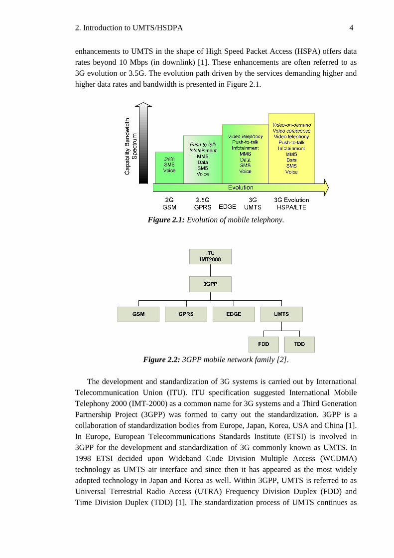
enhancements to UMTS in the shape of High Speed Packet Access (HSPA) offers data rates beyond 10 Mbps (in downlink) [1]. These enhancements are often referred to as 3G evolution or 3.5G. The evolution path driven by the services demanding higher and higher data rates and bandwidth is presented in Figure 2.1.
Figure 2.1: Evolution of mobile telephony.
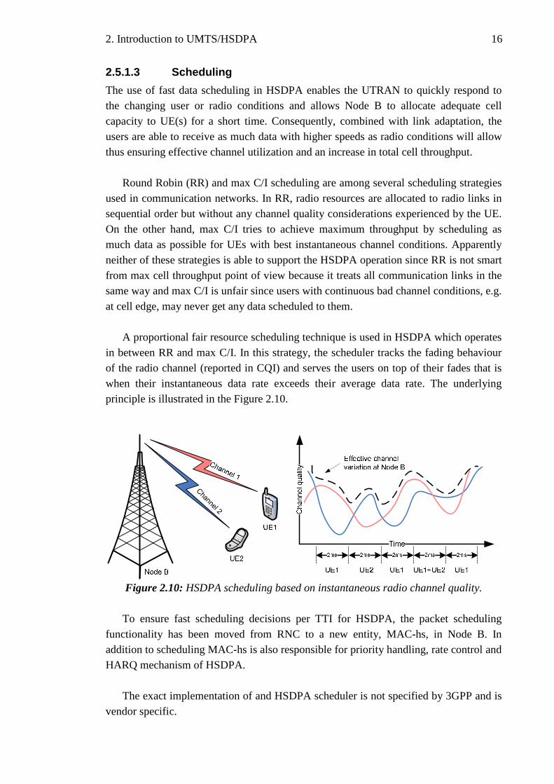
Figure 2.2: 3GPP mobile network family [2].
The development and standardization of 3G systems is carried out by International
Telecommunication Union (ITU). ITU specification suggested International Mobile Telephony 2000 (IMT-2000) as a common name for 3G systems and a Third Generation Partnership Project (3GPP) was formed to carry out the standardization. 3GPP is a collaboration of standardization bodies from Europe, Japan, Korea, USA and China [1]. In Europe, European Telecommunications Standards Institute (ETSI) is involved in 3GPP for the development and standardization of 3G commonly known as UMTS. In 1998 ETSI decided upon Wideband Code Division Multiple Access (WCDMA) technology as UMTS air interface and since then it has appeared as the most widely adopted technology in Japan and Korea as well. Within 3GPP, UMTS is referred to as Universal Terrestrial Radio Access (UTRA) Frequency Division Duplex (FDD) and Time Division Duplex (TDD) [1]. The standardization process of UMTS continues as

2. Introduction to UMTS/HSDPA 5
new techniques to enhance data rates and improve system performance are deployed. The process spans over Release 99 (initial release), Release 4, Release 5 (HSDPA), Release 6 (HSUPA), Release 7 and Release 8 (Long Term Evolution - LTE). The 3GPP mobile network family is shown in Figure 2.2. The work in this thesis has been carried out on UTRA FDD and 3GPP Release 5 network.
2.2. UMTS Architecture
A UMTS network consists of three subsystems: User Equipment (UE), UMTS Terrestrial Radio Access Network (UTRAN) and Core Network (CN). Each subsystem has several logical network elements with a defined functionality and all these elements interact with each other through different interfaces. Figure 2.3 illustrates an overview of UMTS subsystems and interfaces.
Node B
Node B
Node B
RNC
RNC
HLR
SGSN WWW
GMSCPLMN, PSTN,
ISDN...
GGSN
Uu Iub
RNS1
UTRAN
Iur
RNS2
MSC/VLR
CN
Iu-PS
Iu-CS
UE
Figure 2.3: UMTS network architecture.
UE consists of Mobile Equipment (ME) and UMTS Subscriber Identity Module
(USIM). ME is the terminal that contains the operating elements for the user interface e.g. keyboard, display, multimedia features etc. and radio equipment to communicate with UTRAN over Uu interface. USIM is a chip card that contains user specific information, network authentication and security keys for data encryption [1, 5].
The main purpose of UTRAN is to manage data connection and resources between
the UE and the CN and to encapsulate all radio functionalities from the CN. The UTRAN consists of one or more Radio Network Subsystems (RNS) connected to CN through the Iu interface. Each RNS further consists of a Radio Network Controller (RNC) connected to one or more radio base stations via Iub interface [1, 6]. In UMTS

2. Introduction to UMTS/HSDPA 6
the base station is referred to as a Node B. A Node B handles the radio transmission and reception between UE over radio interface (Uu) and some basic radio resource management tasks such as inner loop power control. The RNC, as the name suggests, is the control node in RNS and is responsible for the radio resource management tasks like load control, admission control, congestion control, power control, handover control, code allocation to name a few. These tasks are described in detail later in this chapter. The RNCs can be interconnected to each other via an Iur interface. For each connection between UE and UTRAN, one RNS is the serving RNS. When required, drift RNSs support the serving RNS by providing macro diversity combining and splitting. The role of an RNS (serving or drift) is on a per connection basis between UE and UTRAN [1, 6].
The Core Network (CN) in UMTS corresponds to that of GSM and is responsible
for managing subscriber information and transporting user data to its respective destination. CN is connected to UTRAN via Iu interface and depending on the type of data service it can be separated into two domains: circuit switched (CS) and packet switched (PS). Thus, the Iu interface can also be separated into Iu-CS and Iu-PS for connecting respective CN domains with UTRAN as shown in Figure 2.3. The network entities that handle CS services are Mobile Services Switching Centre (MSC)/Visitor Location Register (VLR) and Gateway MSC (GMSC). MSC is a switching node responsible for serving UE connections with external CS networks e.g. Public Land Mobile Network (PLMN), Public Switched Telephone Network (PSTN) etc. VLR is a dynamic database integrated with MSC that stores visiting user’s service profile for the purpose of location management [5]. GMSC is the gateway node that connects UMTS PLMN to external CS networks. All incoming and outgoing CS connections pass through GMSC. For PS transmission, Serving GPRS Support Node (SGSN) performs similar tasks as MSC/VLR and Gateway GPRS Support Node (GGSN) acts as a routing gateway to external PS networks e.g. Internet. A central database, Home Location Register (HLR), is also present in the CN which contains master copy of subscriber’s service profile, roaming areas, authorization information and current location information (MSC and/or SGSN level). HLR interacts with all the CS and PS entities of core network as illustrated in Figure 2.3.
2.3. WCDMA for UMTS
In any mobile communication system, coverage and capacity are key parameters which are mainly dependent on the signal to interference ratio (SIR) and bandwidth of the access technology used to share the transmission medium (radio interface). 2G systems used TDMA and FDMA techniques for radio interface whereas Code Division Multiple Access (CDMA) technique was employed by 3G systems. In TDMA, all users transmit using the same frequency but the data is multiplexed in short consecutive time slots. In FDMA, the frequency spectrum is divided into small sub frequency channels and user

2. Introduction to UMTS/HSDPA 7
data is multiplexed on these channels at the same time. In CDMA technique, all users transmit simultaneously in the same frequency channel but are separated by different orthogonal codes. These multiple access schemes are presented in Figure 2.4.
Channel 4
Channel 3
Channel 2
Channel 1
Time
Time
Channel 1
Channel 2
Channel 3
Channel 4
Figure 2.4: Multiple access schemes for air interface (a) CDMA (b) TDMA (c) FDMA.
As part of 3GPP standardization, Wideband CDMA (WCDMA) was selected to be
the radio interface for UMTS. The key parameters of WCDMA are given in table 2.1. WCDMA is based on Direct Sequence CDMA (DS-CDMA) technology which has two modes of operation and as mentioned earlier only UTRA FDD mode is considered in this thesis. Frequency bands allocated for UTRA FDD are 1920-1980 MHz in uplink and 2110-2170 MHz in downlink direction. The nominal carrier spectrum of a WCDMA signal is 5 MHz with the centre frequency of the channel in the raster of 200
kHz. However, practical WCDMA signal bandwidth is 4.68 MHz (3.84 MHz x α )
where α = 1.22; is the raised cosine filter roll-off factor.
Table 2.1: WCDMA air interface parameters for UMTS [2]
Parameter Value
Modulation DS-CDMA with QPSK
Chip rate 3.84 Mchips/s
Bandwidth 4.68 MHz Centre frequency in raster of 200 kHz
Duplexing FDD and TDD
Frame length 10 ms frame, 15 time slots
FDD frequency band 2110-2170 MHz (DL) 1920-1980 MHz (UL)
TDD frequency band 2020-2025 MHz (DL) 1900-1920 MHz (UL)
The wideband nature of WCDMA comes from generating a spread spectrum signal for transmission where the bandwidth of information signal is spread over a wider frequency bandwidth. This spreading at transmitting end (and de-spreading at receiving end) is done by multiplying user data sequence with a spreading sequence that has a

2. Introduction to UMTS/HSDPA 8
symbol (or chip) rate much higher than the user data rate. The ratio between the chip rate and user data rate is called spreading factor [2]:
chip
user
RSF
R= . (2.1)
A constant chip rate of 3.84 Mchip/s and spreading factor range of 4 to 512 is used in WCDMA system for spreading the signal. An example of spreading and de-spreading process is shown in the Figure 2.6. The spread spectrum modulation is a fundamental aspect of WCDMA since it allows the possibility of combining different data services in the same radio channel and also provides high tolerance and robustness against narrowband interference added by the transmission channel. At WCDMA receiver, the wideband spread spectrum signal is de-spread thus increasing the power density of the carrier signal and at the same time narrowband interference is spread to wideband which makes it undetectable as compared to the carrier signal. This is illustrated by Figure 2.7. The amount by which power density of the carrier signal is increased in the receiver is called processing gain (PG) [5]. PG is the same as spreading factor but is represented in dB by equation (2.2): ( )1010 logPG SF= ⋅ . (2.2)
Figure 2.6: Spreading and de-spreading in DS-CDMA [1].

2. Introduction to UMTS/HSDPA 9
cf
if
f
if
cf
f
Figure 2.7: De-spreading and filtering of WCDMA signal.
2.3.1. Code Allocation
In a WCDMA network, two different types of codes are used. Channelization codes are Orthogonal Variable Spreading Factor (OVSF) codes and are used to separate different users in downlink (within one cell) and to separate data & control channels of a single user in the uplink. Additionally, Scrambling codes are used to separate different base stations (or cells) in downlink and to separate different users in the uplink direction. Channelization codes increase the transmission bandwidth (spreading) however; scrambling codes have no affect on the bandwidth [1].
2.3.2. UTRA Physical Layer: Channels and Signalling
Signalling and data flow in WCDMA happens in three planes: transport, control and user plane. The transport plane is UTRA (air) interface that provides connection between UE and UTRAN [15]. Transport plane is further classified into three layers: physical (L1), data link (L2) and network (L3). L2 and L3 are further divided into sublayers. The overall communication takes place in several different channels which are divided among the three layers. Logical channels provide data transfer within the Medium Access Control (MAC; L2 sublayer) while transport channels carry data from logical channels over the physical layer. There are different types of transport channels with different characteristics that are mapped to physical channels in the physical layer. Common transport channels (FACH, RACH, DSCH, BCH and PCH) are shared by multiple UEs whereas dedicated transport channels (DCH) are allocated to a single UE at a time. The services provided by physical layer include macro diversity combining, channel coding and interleaving, multiplexing of transport channels, mapping to physical channels, modulation and spreading, closed-loop power control and much more [9].
The transmission at physical layer is split into radio frames of 10 ms duration. Each frame consists of 15 slots and each slot consists of 2560 chips which correspond to one power control period. Moreover each slot in the radio frame carries a set of common and dedicated channels. The channel coding can be changed in every radio frame which provides flexibility in offering variable bit rate [2, 16]. In addition to data traffic, a lot of control and signalling information also needs to be exchanged between Node B and UE

2. Introduction to UMTS/HSDPA 10
for proper functioning of the network therefore the channels are also classified into traffic and signalling channels.
A complete listing and mapping of logical, transport and physical channels are out
of the scope of this thesis but they are presented in the specifications [9] and [16]. However, few relevant L1 and L2 sublayers and channels are described later in the following sections.
2.4. Radio Resource Management
UMTS is typically an interference limited system since all users are using the same frequency over the whole network. Therefore radio resource management (RRM) plays an important role for efficient utilization of the shared radio resources and to guarantee Quality of Service (QoS) for the planned coverage and capacity. UMTS RRM algorithms can be classified into handover control, power control, admission control, load control and packet scheduling functionalities [1]. Accordingly UE, Node B and RNC actively participate in these functionalities.
The concept of power control (PC) is very critical in UMTS as it has a great impact on the capacity of the network. Since all users and Node Bs are transmitting in the same frequency, it is important to keep the transmission power in uplink and downlink adequately low enough for the receiver to detect it thereby keeping the overall interference at an acceptable level and saving transmit power resources. This means the power of transmitter should be tuned based on the service being used and location of the transmitter (to avoid near-far effect in uplink). In UMTS, PC is done by several algorithms known as open loop PC, closed inner loop PC and closed outer loop PC.
The idea of mobility in cellular networks is to provide constant service to the user while on move which may require a cell change or network change in case the user is moving from the service area of one base station to the other. This concept is known as handover. In GSM the handovers are done as hard handover (HHO) i.e. old resources and connections are released before acquiring new ones. However, UMTS introduces a new concept of soft handover (SHO) where one UE can stay connected to two or more Node Bs simultaneously. This usually happens on the cell boundaries (called SHO areas), where UE is able to detect two or more cells as the serving cells. The data received from multiple connections in SHO situation is combined in uplink (at RNC) and in downlink (at UE) which provides link diversity. SHO provides benefit against fading since the UE is always connected to the best server and also improved radio performance due to diversity [2]. Softer handover (SfHO) is similar to SHO except that in SfHO, the UE is connected to the adjacent sectors of the same Node B. In UMTS, handovers can be intra-frequency (SHO or HHO), inter-frequency (HHO) and inter-system (HHO).

2. Introduction to UMTS/HSDPA 11
Admission and load control functionalities work hand in hand with each other to
optimize and maximize the UMTS network capacity and coverage. When a new UE connection is requested, admission control ensures that accepting this new link will not result in interference to the required QoS for existing connections. Load control on the other hand tries to maximize the throughput of the network without endangering the quality or coverage of the network and ensures that the network doesn’t become overloaded.
2.5. High Speed Downlink Packet Access (HSDPA)
One of the significant improvements in the development of 3G systems was the support of high packet data throughput to improve the end-user experience of multimedia and data centric services on mobile. Release 99 WCDMA was already able to provide peak data rate of 384 kbps with a latency of 100-200 ms which is quite close to a low end digital Internet connection [17]. High Speed Downlink Packet Access (HSDPA) technology is a result of continued WCDMA evolution to support even higher data throughput, lower latency and improved downlink capacity for packet data services. HSDPA was standardized as part of 3GPP Release 5 specification and its uplink counterpart, High Speed Uplink Packet Access (HSUPA), in 3GPP Release 6. Together both these technologies form WCDMA evolution generally termed as High Speed Packet Access (HSPA) or sometimes 3.5G. This section provides necessary background information about HSDPA technology along with the physical layer structure as well as few key performance indicators (KPI) which are important to understand this thesis work.
2.5.1. HSDPA Technology
The HSDPA concept is designed to facilitate peak data rates beyond 10 Mbps (potentially up to 14.4 Mbps) in downlink utilizing methods known already from EDGE evolution in GSM [1, 17]. In principle, the throughput is increased with the introduction of several new technical enhancements to the UTRAN which are briefly listed below and explained thereafter:
• The use of a new common transport channel; High Speed Downlink Shared Channel (HS-DSCH) which can be shared by multiple users simultaneously.
• A shorter Transmission Time Interval (TTI) of 2ms in the physical layer to reduce end user delay and enable high transmission speeds.
• The use of fast scheduling by MAC high speed (MAC-hs) layer in Node B.
• The use of higher order modulation and link adaptation termed as Adaptive Modulation and Coding (AMC) in HSDPA.

2. Introduction to UMTS/HSDPA 12
• The use of fast retransmission techniques based on Hybrid Automatic Repeat reQuest (HARQ) with soft combining.
• The use of multiple (up to 15) SF-16 channels for one user.
2.5.1.1 High speed downlink shared channel (HS-DSCH )
HSDPA exploits the concept of shared-channel transmission which means that a part of total downlink radio resources (transmission power and channelization codes) are dynamically and efficiently shared between users in time domain. A new shared transport channel, HS-DSCH, is implemented in HSDPA which enables the UTRAN to rapidly allocate a significant portion of downlink resources for bursty packet data transmission to a specific user for a short period of time. This time and code sharing transmission is illustrated in the Figure 2.8.
(a) Code sharing
Channelization codes
(b) Time sharing
Figure 2.8: (a) Code and (b) Time domain structure of HS-DSCH [18].
HSDPA employs a constant spreading factor of 16 (SF-16) with a maximum of 15
parallel configurable codes available for a short TTI of 2 ms for HS-DSCH transmission. During each TTI (2 ms), all these codes are rapidly allocated to a specific user or split among several HSDPA users. The use of such short TTI provides a significant improvement in end user delay as compared to 10 ms TTI of Release 99 WCDMA and is also important for supporting rapid link adaptation to varying channel conditions. Codes not allocated to HS-DSCH transmission are used by other related control signalling, circuit-switched services or Release 99 packet-switched services.

2. Introduction to UMTS/HSDPA 13
In addition to code sharing, a part of total transmission power also needs to be allocated for HS-DSCH transmission. In WCDMA, this is typically achieved by power control. However, the concept of power control is not applied in HSDPA. Therefore to efficiently utilize the Node B power, either a fixed part of total available power is allocated for HS-DSCH transmission or after allocating power to common control and dedicated channels, remaining power is used for HS-DSCH transmission. On the other hand, modulation, coding and number of codes are dynamically and rapidly changed to adapt to the variations in radio conditions [17, 18]. This link adaptation will be explained under adaptive modulation and coding section.
At physical layer, HS-DSCH is mapped to high-speed Physical Downlink Shared
Channel (HS-PDSCH). Associated signalling information is carried via two control channels. In downlink signalling, high-speed Shared Control Channel (HS-SCCH) carries UE identity, type of modulation and coding, transport format and HARQ related information. In uplink, signalling related to HARQ acknowledgements is carried on high-speed Dedicated Physical Control Channel (HS-DPCCH). Moreover in HSDPA, Node B requires information about the instantaneous radio channel conditions of the UE for rate control and link adaptation. Therefore each UE also measures the instantaneous downlink radio channel quality and transmits a Channel Quality Indicator (CQI) in uplink on HS-DPCCH [18, 19]. This reported CQI value is not related to the Signal to Interference Ratio (SIR) at UE rather it is a function of multipath environment, terminal receiver type, interference ratio of own cell to the others and expected Node B HSDPA power availability [17]. CQI has a significant role in HSDPA operation and its affect will be further studied in the measurements chapter.
Additional signalling required for normal UMTS operation and data for CS services
is still carried in parallel by downlink Dedicated Physical Control Channel (DPCCH) and Dedicated Physical Data Channel (DPDCH) respectively for each UE. The overall channel structure of HSDPA is illustrated in the Figure 2.9.

2. Introduction to UMTS/HSDPA 14
Figure 2.9: HSDPA channel structure.
2.5.1.2 Adaptive Modulation and Coding
Typically in mobile communications, the radio channel conditions between Node B and every UE vary significantly due to UE position, interference from surroundings and other propagation phenomena. To neutralize the effect of these instantaneous channel conditions, the so called concept of link adaptation is applied in WCDMA in the form of power control to ensure sufficient energy per information bit for all communication links [18]. HSDPA also exploits the concept of link adaptation rather deeply using rate control. However, as mentioned earlier, this is not done using power control but by dynamically adjusting the coding rate, modulation scheme and number of codes used for HS-DSCH according to the varying channel conditions of HSDPA users thus leading to a higher data rate for users with favourable radio conditions. This link adaptation, also known as adaptive modulation and coding, is applied by Node B in every 2 ms TTI based on physical layer CQI reported by the UE.
It is sufficient to mention here that, fundamentally, HSDPA uses 1/3 rate turbo coding with additional rate matching for HS-DSCH as opposed to convolutional coding. Rate matching is applied to adapt to the desired coding rate and is typically done using either puncturing or repetition [17, 18]. Moreover, to facilitate higher data rates, HSDPA uses higher order 16-Quadrature Amplitude Modulation (QAM) in addition to Quadrature Phase Shift Keying (QPSK) modulation used in standard UMTS Release 99. When the instantaneous radio link is sufficiently robust, the use of 16-QAM and a higher coding rate leads to higher bandwidth utilization and a significant increase in HSDPA throughput. The selection of an effective modulation scheme and channel coding rate is referred to as Transport Format Resource Combination (TFRC) [19]. An effective TFRC recommendation well suited to the radio channel conditions is reported

2. Introduction to UMTS/HSDPA 15
by UE as part of CQI measurements which Node B may adapt for next TTI. Table 2.2 shows an example theoretical bit rates achievable by different TFRCs.
Table 2.2: TFRCs and corresponding user data rates at physical layer [21].
TFRC Modulation Eff. code rate
Data rate 5 codes
Data rate 10 codes
Data rate 15 codes
1 QPSK 14
0.6 Mbps 1.2 Mbps 1.8 Mbps
2 QPSK 24
1.2 Mbps 2.4 Mbps 3.6 Mbps
3 QPSK 34
1.8 Mbps 3.6 Mbps 5.4 Mbps
4 16QAM 24
2.4 Mbps 4.8 Mbps 7.2 Mbps
5 16QAM 34
3.6 Mbps 7.2 Mbps 10.8 Mbps
In addition to the instantaneous channel conditions, reported TFRC also depends on UE’s ability to handle the higher order modulation as well as multiple parallel codes. This dependency is typically limited by UE receiver architecture and has a significant impact on the peak data rates that a UE can achieve even in best possible conditions. Table 2.3 lists the different UE categories and their supported data rates as defined by 3GPP specifications in [20] and in reference [1].
Table 2.3: HSDPA UE categories and supported data rates [1, 20].
UE Category
Modulation Scheme Nr. of HS-DSCH Codes
Nr. of Soft Channel bits
Peak Data Rate
11 QPSK 5 14400 0.9 Mbps
12 QPSK 5 28800 1.8 Mbps
1 QPSK or 16 QAM 5 19200 1.2 Mbps
2 QPSK or 16 QAM 5 28800 1.2 Mbps
3 QPSK or 16 QAM 5 28800 1.8 Mbps
4 QPSK or 16 QAM 5 38400 1.8 Mbps
5 QPSK or 16 QAM 5 57600 3.6 Mbps
6 QPSK or 16 QAM 5 67200 3.6 Mbps
7 QPSK or 16 QAM 10 115200 7.2 Mbps
8 QPSK or 16 QAM 10 134400 7.2 Mbps
9 QPSK or 16 QAM 15 172800 10.2 Mbps
10 QPSK or 16 QAM 15 172800 14.4 Mbps
2. Introduction to UMTS/HSDPA 16
2.5.1.3 Scheduling
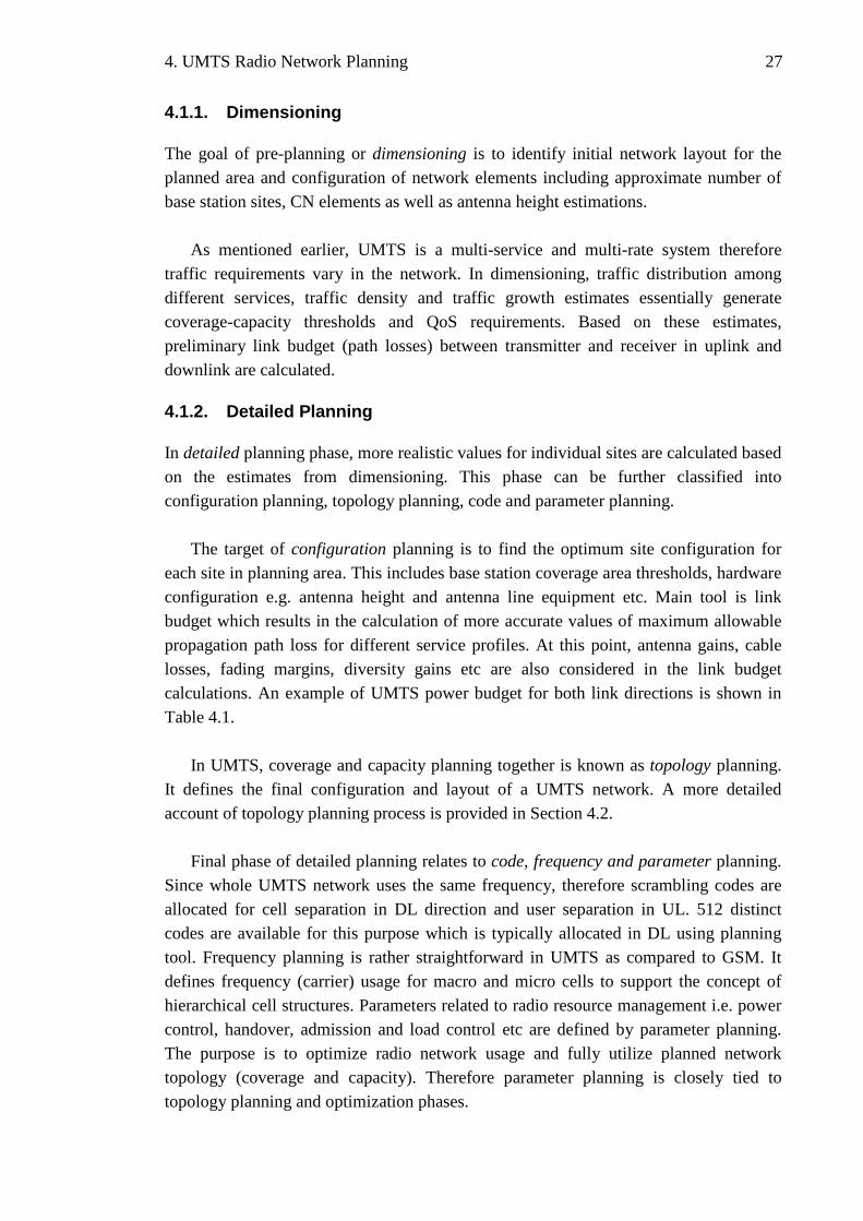
The use of fast data scheduling in HSDPA enables the UTRAN to quickly respond to the changing user or radio conditions and allows Node B to allocate adequate cell capacity to UE(s) for a short time. Consequently, combined with link adaptation, the users are able to receive as much data with higher speeds as radio conditions will allow thus ensuring effective channel utilization and an increase in total cell throughput.
Round Robin (RR) and max C/I scheduling are among several scheduling strategies used in communication networks. In RR, radio resources are allocated to radio links in sequential order but without any channel quality considerations experienced by the UE. On the other hand, max C/I tries to achieve maximum throughput by scheduling as much data as possible for UEs with best instantaneous channel conditions. Apparently neither of these strategies is able to support the HSDPA operation since RR is not smart from max cell throughput point of view because it treats all communication links in the same way and max C/I is unfair since users with continuous bad channel conditions, e.g. at cell edge, may never get any data scheduled to them.
A proportional fair resource scheduling technique is used in HSDPA which operates
in between RR and max C/I. In this strategy, the scheduler tracks the fading behaviour of the radio channel (reported in CQI) and serves the users on top of their fades that is when their instantaneous data rate exceeds their average data rate. The underlying principle is illustrated in the Figure 2.10.
Channel 2
Figure 2.10: HSDPA scheduling based on instantaneous radio channel quality.
To ensure fast scheduling decisions per TTI for HSDPA, the packet scheduling
functionality has been moved from RNC to a new entity, MAC-hs, in Node B. In addition to scheduling MAC-hs is also responsible for priority handling, rate control and HARQ mechanism of HSDPA.
The exact implementation of and HSDPA scheduler is not specified by 3GPP and is
vendor specific.

2. Introduction to UMTS/HSDPA 17
2.5.1.4 Hybrid ARQ with Soft Combining
To compensate for errors in data transmission and link adaptation process, HSDPA uses HARQ mechanism for retransmission which is based on Stop and Wait (SAW) protocol. Moreover, in order to support fast HSDPA operation, HARQ is implemented in MAC-hs and physical layer which enables Node B to quickly respond to multiple retransmission requests of UE without involving higher layers thus resulting in lower retransmission roundtrip delay - as low as 12 ms [21].
In a typical SAW, Node B keeps the current transmitted block in its buffer and holds off further transmission until it receives a successful acknowledgement (ACK) from the UE. However, to utilize the radio link during this waiting time, HSDPA configures up to N (max. 8) parallel SAW transmissions for the same UE in separate TTIs.
The probability of successfully decoding the transport block is increased by
combining the retransmission(s) with the original transmission at UE. This is known as soft combining. HSDPA supports Incremental Redundancy (IR) and Chase Combining (CC) retransmission strategies for the purpose of soft combining. The principle of IR is based on non-identical retransmissions of the erroneous block, that is, every time a different rate matching (redundancy pattern) is used for retransmission(s) of the same block. UE buffers the bits from erroneous transmission(s) of a block and soft combines them with the bits from retransmission(s) thus attempting to decode the combination. On the contrary, CC uses identical rate matching for every retransmission of the same block. The decision to use IR or CC for retransmission lies with Node B [18].
The use of HARQ with soft combining increases the total received energy per
information bit ( b oE I ). Moreover, in order to achieve high spectral efficiency in
HSDPA, UE attempts to keep the transport Block Error Rate (BLER) at 10% by varying the CQI values.
A more detailed description on HSDPA physical layer operation, modulation,
coding schemes and HARQ functionality can be found in the references [17] and [18].
2.5.2. Mobility and Handovers
Mobility management or more specifically handover management in HSDPA differs from that of Rel’99 WCDMA mainly because SHO is not applied and HS-DSCH is always transmitted from a single Node B to the UE. However, associated DCH may continue to perform SHO as normally [17]. Alternatively, a direct handover is performed between the HS-DSCH of the serving and target Node B by physical channel reconfiguration. The key idea is to continue HSDPA transmissions regardless of UE position in the network.

2. Introduction to UMTS/HSDPA 18
The handover decision is triggered by RNC and is based on measurement report sent by UE after it detects a stronger P-CPICH other than the serving cell (measurement event 1D). The reconfiguration process can be asynchronous, that is, involved network entities respond to the reconfiguration message as soon as it is received; or synchronous which implies that an activation time is sent to the involved entities ensuring that all the reconfigurations are done at the same time. Since asynchronous reconfiguration may result in potential data loss therefore synchronous approach is typically applied in HS-DSCH handovers between Node Bs. During the handover, corresponding MAC-hs protocols are reset in serving Node B and UE including unfinished HARQ processes; therefore, possible packet losses are handled by standard RLC functionality.
2.5.3. HSDPA Performance
Peak HSDPA performance revolves around its capability to adapt itself to the changing radio conditions by efficient combination of all the features introduced in previous sections. Additionally, accuracy of RRM algorithms, UE receiver performance and demodulation capability, interference levels based on propagation loss, mobility patterns, QoS requirements, and hardware limitations also affect HSDPA performance.
Qualitatively, energy per bit over noise spectral density ( b oE N ) is typically used to
determine an acceptable bit error rate for a certain data rate. Since HSDPA bit rates are changed in every TTI with link adaptation therefore, performance is typically affected
by effective Signal to Interference plus Noise Ratio (SINR) which is defined by equation (2.3) [17] as:
16 (1 )HS DSCH
own other noise
PSINR SF
P P Pα−=
− ⋅ + +, (2.3)
where 16SF is the processing gain for spreading factor 16, HS DSCHP − is the received
power of the HS-DSCH channel, α is own-cell orthogonality factor, ownP represents
own-cell interference, otherP is other-cell interference and noiseP is the receiver thermal
noise.

19 19
3. RADIO PROPAGATION IN UMTS
Radio propagation in cellular communications happens in the air interface where radio waves travel between the transmitters and receivers, ideally, taking a direct path (free space propagation). However, the propagation is typically affected by the environment, natural phenomena and man-made obstacles, which results in for example signal attenuation and multipath propagation. This chapter describes some basic radio propagation phenomenon, channel characteristics and different propagation environments that affect the behaviour of the UMTS system.
3.1. Radio Channel and Signal Propagation
The characteristics of a typical radio propagation channel can be defined by parameters like propagation slope, signal fading, multipath propagation, angular spread, delay spread and coherence bandwidth.
3.1.1. Propagation Slope
The propagation slope defines the amount of signal attenuation between transmitter and receiver as a function of distance (in dB/dec). The simplest case of signal propagation is free space propagation where the radio wave is not obstructed by any obstacles and signal attenuation depends only on the frequency and distance travelled. Mathematically, Friis’s transmission equation (3.1) defines free space propagation as: 2
4r
t rt
PG G
P d
λπ
=
, (3.1)
where tP is the transmitted power, rP is the received power, tG is transmitter gain, rG
is the receiver gain, λ is the wavelength and d is the distance between transmitter and receiver.
3.1.2. Multipath Propagation
In a typical mobile radio channel, the signal propagation undergoes different phenomena like reflections, diffractions etc. due to multiple obstacles present between the transmitter and receiver. Consequently, the receiver receives multiple delayed components of the signal with different amplitude and phase attenuations. The components are known as multipath components and the phenomenon is called

3. Radio Propagation in UMTS 20
multipath propagation. If the transmitted signal takes a direct path to reach the receiver then the propagation is called Line of Sight (LOS) propagation. All other multipath components are Non Line of Sight (NLOS). An example of a multipath propagation environment is presented in Figure 3.1.
Node B UE
reflection
direct
diffraction
Figure 3.1: Multipath propagation.
The deviation of received signal incident angle is defined as angular spread. It can
be calculated using equation (3.2):
( ) ( )1802
_180 TOT
PS d
P
Φ+
ΦΦΦ−
Φ= Φ − Φ Φ∫ , (3.2)
where Φ is the mean incident angle, ( )P Φ is the angular power distribution, and
_TOTPΦ is the total power.
In a multipath environment, the multipath components travel paths of different
lengths and thus arrive at different times at the receiver. This time variation is defined as
delay spread ( Sτ ) and can be calculated from the received power as a function of delay
( ( )Pτ τ ):
( ) ( )2
0
_TOT
P d
SP
τ
ττ
τ τ τ τ∞
−=∫
, (3.3)
where τ is average is delay and _TOTPτ is the total received power. ( )Pτ τ is also
known as power delay profile (PDP) and is typically presented as impulse (power) response of the channel.

3. Radio Propagation in UMTS 21
When observed in frequency domain, different frequencies attenuate differently. This is known as frequency selective fading. The bandwidth over which two frequencies
of a signal experience the same fading is called coherence bandwidth ( cf∆ ). In order to
have uncorrelated fading between two multipath components, the frequency separation needs to be equal or higher than the coherence bandwidth. It is represented as a function of delay spread in equation (3.4): 1
2cf Sτπ∆ = . (3.4)
Moreover, in multipath propagation, the motion of transmitter or receiver typically
causes frequency dispersion of the received signal. This is known as Doppler spread
( df ) and is expressed by equation (3.5):
coscd
vf f
cθ= , (3.5)
where cf is the carrier frequency, v is the velocity of motion, c is the speed of light
and θ is the angle between direction of motion and direction of incident signal.
It is important to mention here that a cellular system is considered wideband when the signal bandwidth is much larger than the coherence bandwidth of the channel. On the contrary the system is narrowband if the signal bandwidth is less than the coherence bandwidth.
3.1.3. Fading
Multipath propagation and moving receivers (UEs) result in random changes in the amplitude, phase and angle of arrival of the received components. These components are combined in the receiver using constructive and destructive combining (superposition principle) that result in rapid fluctuations in the received signal level. This is called fast fading. In a NLOS situation, when there is no direct path component, the amplitude variations are quite large and the phases of the components have random uniform distribution. In such a fading channel, amplitude is modelled by Rayleigh distribution and, therefore, is also referred to as Rayleigh fading. However, in a LOS situation, the amplitude has Ricean distribution due to the presence of a direct strong component and such a fading is known as Ricean fading [10].
The received signal also experiences slow fading which is caused by the shadowing due to large obstacles e.g. buildings, mountains etc. Slow fading is the variation of the local mean value of fast fading signal over a wider area and has a log-normal
3. Radio Propagation in UMTS 22
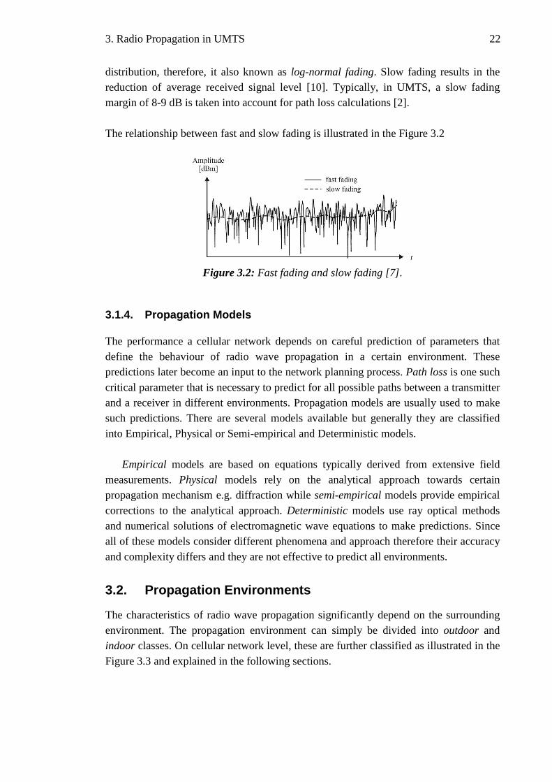
distribution, therefore, it also known as log-normal fading. Slow fading results in the reduction of average received signal level [10]. Typically, in UMTS, a slow fading margin of 8-9 dB is taken into account for path loss calculations [2]. The relationship between fast and slow fading is illustrated in the Figure 3.2
Figure 3.2: Fast fading and slow fading [7].
3.1.4. Propagation Models
The performance a cellular network depends on careful prediction of parameters that define the behaviour of radio wave propagation in a certain environment. These predictions later become an input to the network planning process. Path loss is one such critical parameter that is necessary to predict for all possible paths between a transmitter and a receiver in different environments. Propagation models are usually used to make such predictions. There are several models available but generally they are classified into Empirical, Physical or Semi-empirical and Deterministic models.
Empirical models are based on equations typically derived from extensive field measurements. Physical models rely on the analytical approach towards certain propagation mechanism e.g. diffraction while semi-empirical models provide empirical corrections to the analytical approach. Deterministic models use ray optical methods and numerical solutions of electromagnetic wave equations to make predictions. Since all of these models consider different phenomena and approach therefore their accuracy and complexity differs and they are not effective to predict all environments.
3.2. Propagation Environments
The characteristics of radio wave propagation significantly depend on the surrounding environment. The propagation environment can simply be divided into outdoor and indoor classes. On cellular network level, these are further classified as illustrated in the Figure 3.3 and explained in the following sections.

3. Radio Propagation in UMTS 23
Figure 3.3: Classification of propagation environments.
3.2.1. Outdoor (Macro- and Micro-cell)
Outdoor environment is typically classified into macro-cellular and micro-cellular environments. Generally, macro-cellular corresponds to the environment where the base station (Node B) antenna height is above the average rooftop level. Accordingly microcellular corresponds to the environment where the antenna height is below the average rooftop level. Macro-cellular environment can be divided into urban, suburban and rural area types based on varying characteristics of obstacles and terrain structure (buildings, trees, mountains etc.) surrounding the Node B and UE. In urban areas, building dimensions and density obstructs the propagation path significantly therefore microcellular environment is typically built in such areas to avoid shadowing and improve coverage.
3.2.2. Indoor (Pico-cell)
Pico-cellular environment corresponds to the indoor scenario when the Node B antenna is located inside a building. Since most of the users are located indoors for most of the time therefore, pico-cells are usually created to serve such high traffic areas e.g. inside office buildings, shopping malls, airports etc. Alternatively, a radio signal from macro-cellular and micro-cellular systems penetrating into the building also contributes towards indoor propagation; acting either as interference or as means of providing extended coverage without capacity [11].
3.2.3. Indoor Propagation Channel
The special characteristics of WCDMA propagation in indoor (compared to outdoor) channel are presented in Table 3.1 and discussed in this section since the measurements for the thesis were carried out in an indoor environment.
Radio propagation in indoor environment differs from the outdoor mainly due to close proximity of reflecting structures (walls, floors etc.), mobility of UE, usage of different construction materials, density of people and furniture; all resulting in random behaviour and strong fluctuations in average received signal level (higher slow fading). Large reflective surfaces surrounding the Node B antenna causes wide angular spread thus compromising antenna diversity reception techniques. Delay spread is very critical

3. Radio Propagation in UMTS 24
because WCDMA uses a special receiver (RAKE) whose performance depends on the multipath propagation and channel characteristics. RAKE receiver provides optimum performance by combining multipath components using Maximal Ratio Combining (MRC) technique. Therefore, the larger the number of multipath components that can be separated the better is the performance of RAKE receiver [10]. 0.26 µs is the smallest delay between multipath components to enable separation [13]. In an indoor channel, the propagation distance between transmitter and receiver is usually short which results in small delay spreads (<< 0.26 µs). Consequently, all or most of the multipath components lie within the same chip interval therefore RAKE receiver is unable to separate them and use them for efficient combining. Power delay profile of an indoor channel is presented in Figure 3.4.
Table 3.1: Delay spread, coherence bandwidth and propagation channel types [2]. Delay spread
(µs) Coherence bandwidth
(MHz)
WCDMA
Bandwidth 3.84 MHz
Macro-cell (Urban)
0.5 0.32 WB
Macro-cell (Rural)
0.1 1.6 NB/WB
Macro-cell (Hilly)
3 0.053 WB
Micro-cell < 0.1 > 1.6 NB/WB
Indoor < 0.01 > 16 NB
WB = wideband; NB = narrowband
0
0.05
0.1
0.15
0.2
0 0.2 0.4 0.6 0.8 1 1.2 1.4 1.6 1.8 2
Delay [ms]
Pow
er [d
Bm
]
Correlater delayCorr1
Figure 3.4: An example of indoor channel and RAKE receiver finger delay

3. Radio Propagation in UMTS 25
Moreover, coherence bandwidth (frequency domain property) of a channel is
inversely dependent on delay spread; therefore a smaller delay spread would result in higher coherence bandwidth. As mentioned previously, the system is considered narrowband if the channel coherence bandwidth is greater than the system bandwidth which establishes the fact that WCDMA behaves as a narrowband system in indoor environment. This behaviour is also presented in Table 3.1 which lists the coherence bandwidth of indoor channel as high as 16 MHz as compared to 3.84 MHz WCDMA system bandwidth. A narrowband system results in frequency non-selective or flat fading behaviour with no means to exploit multipath diversity [10, 13].
The indoor environment is a non stationary time and space-variant channel due to
the movement of UE and/or scattering objects [12]. It is very difficult to establish a universal path loss model due to varying characteristics of the building and obstructing material. Thus it is sufficient to tune existing propagation models by considering path loss over a certain distance and additional loss factors related to signal penetration through walls and floors of different types. One such approach introduced by 3GPP specifications [14] is derived from COST 231 multi-wall model presented in [11]. (( 2) /( 1) 0.46)
101
37 20 ( ) 18.3w
n nwi wi
i
L log R k L n + + −
=
= + + +∑ , (3.6)
where R is the distance between transmitter and receiver, wik is the number of
penetrated walls of typei , wiL represents the loss of wall type i and n is the number of
penetrated floors. This model typically considers losses related to two different internal wall types that are light and regular.

4. UMTS Radio Network Planning 26
4. UMTS RADIO NETWORK PLANNING
Radio network planning is the most significant continuous process that produces and further ensures a telecommunication network successfully operating with peak performance.
UMTS is a multi-service and multi-rate system that relies on a completely different air interface approach (WCDMA) based on single frequency use in the network thus making it highly vulnerable to interference as compared to GSM system. Moreover unlike GSM, capacity and coverage in UMTS are tightly coupled with each other. Therefore UMTS deployment must be preceded with careful radio network planning.
This chapter highlights different phases that constitute UMTS radio network planning process.
4.1. Planning Process
The main objective of planning process is to maximize coverage, capacity and QoS while meeting the key performance indicators (KPI) [10]. The overall UMTS planning process can be divided into three phases as illustrated in Figure 4.1. The basic principles are the same as in GSM; however, detailed planning phase needs adjustments to suit UMTS requirements.
Figure 4.1: UMTS radio network planning process [2].
UMTS RNP is typically supported by sophisticated hardware and software tools for accurate network planning and verification. High detail digital maps are used alongside GUI based network planning and simulator tools that provide reliable coverage and capacity predictions. Simulations are usually done throughout the actual planning process whereas propagation slope measurements are made during dimensioning and field measurements are performed in an already operational network.
4. UMTS Radio Network Planning 27
4.1.1. Dimensioning
The goal of pre-planning or dimensioning is to identify initial network layout for the planned area and configuration of network elements including approximate number of base station sites, CN elements as well as antenna height estimations.
As mentioned earlier, UMTS is a multi-service and multi-rate system therefore traffic requirements vary in the network. In dimensioning, traffic distribution among different services, traffic density and traffic growth estimates essentially generate coverage-capacity thresholds and QoS requirements. Based on these estimates, preliminary link budget (path losses) between transmitter and receiver in uplink and downlink are calculated.
4.1.2. Detailed Planning
In detailed planning phase, more realistic values for individual sites are calculated based on the estimates from dimensioning. This phase can be further classified into configuration planning, topology planning, code and parameter planning.
The target of configuration planning is to find the optimum site configuration for each site in planning area. This includes base station coverage area thresholds, hardware configuration e.g. antenna height and antenna line equipment etc. Main tool is link budget which results in the calculation of more accurate values of maximum allowable propagation path loss for different service profiles. At this point, antenna gains, cable losses, fading margins, diversity gains etc are also considered in the link budget calculations. An example of UMTS power budget for both link directions is shown in Table 4.1.
In UMTS, coverage and capacity planning together is known as topology planning.
It defines the final configuration and layout of a UMTS network. A more detailed account of topology planning process is provided in Section 4.2.
Final phase of detailed planning relates to code, frequency and parameter planning.
Since whole UMTS network uses the same frequency, therefore scrambling codes are allocated for cell separation in DL direction and user separation in UL. 512 distinct codes are available for this purpose which is typically allocated in DL using planning tool. Frequency planning is rather straightforward in UMTS as compared to GSM. It defines frequency (carrier) usage for macro and micro cells to support the concept of hierarchical cell structures. Parameters related to radio resource management i.e. power control, handover, admission and load control etc are defined by parameter planning. The purpose is to optimize radio network usage and fully utilize planned network topology (coverage and capacity). Therefore parameter planning is closely tied to topology planning and optimization phases.

4. UMTS Radio Network Planning 28
4.1.3. Optimization
A UMTS network may be launched after detailed planning phase however constant monitoring of network is needed. This is due to the fact that user location and traffic behaviour vary constantly which directly affects radio network quality. Optimization is a recurring process in which the network is constantly tested and verified by field measurements and consequently different configurations and parameters e.g. signalling, power control, handover control etc are adjusted [2]. Moreover, KPIs like throughput, interference, call success and failure rate, overload situations, HO rate and many more are constantly analyzed for optimization. The purpose of optimization phase is to ensure that the planned coverage, capacity and quality is achieved and defined KPIs are met.
4.2. Topology Planning
Coverage and capacity of UMTS are planned together under topology planning phase. UMTS is an interference sensitive system in which all users share the same frequency. Increasing the number of users increases the interference which requires more transmit power to be used in the cell. This causes the cell coverage to shrink while the load increases. The phenomenon is known as cell breathing. Therefore in UMTS RNP, both coverage and capacity have to be analyzed simultaneously and together [2]. Coverage and capacity are typically linked together via link budget calculations and load equations respectively which will be explained shortly. Network must be planned so that adequate coverage is available for users at cell edge and indoors in high load situations while keeping the interference low. In addition to coverage area, maximum load (or capacity) depends on base station locations and antenna configurations (height, direction, beamwidth, tilting etc).
Topology planning process can be further classified into coverage predictions, Monte-Carlo simulations, and network performance analysis as shown in Figure 4.2 while Figure 4.3 illustrates the link between the UMTS coverage and capacity planning process.
Figure 4.2: UMTS topology planning process [2].

4. UMTS Radio Network Planning 29
Figure 4.3: Link between coverage and capacity of a UMTS network [2].
First step in coverage prediction is to estimate pilot channel coverage (P-CPICH). In UMTS, maximum transmit power is limited and in DL this power is shared among user traffic (e.g. DCH) as well as signalling channels (e.g. CPICH). Adequate power allocation to CPICH is an important task since its received level is used for cell (re-) selection, channel estimation and HO measurements. Too high power allocation increases the coverage area of pilot channel but at the same time there is less power available for DCH, which in fact, reduces the system capacity. On the contrary too low power allocation for CPICH results in reduction of cell dominance area. Therefore balance between CPICH and DCH power allocation is critical if coverage and capacity needs to be maximized. Typically, 5-10% of the total base station power is reserved for CPICH [2]. Coverage prediction among different cells may vary due to cell specific propagation environment and traffic distribution.
Monte-carlo simulations are system level simulations that are used to estimate
maximum load in the network. The simulations are typically done using RNP tool equipped with digital maps of the area. All the predictions and estimates done in the previous planning phases are mapped in the tool. Users are distributed over the coverage area, all Node Bs and UEs are assigned with transmit powers, interference is introduced and link directions are analyzed for different service profiles. The simulations result in system parameters like cell load, throughput, transmit powers, coverage and interference related information.
Results from simulations are further used in network performance analysis phase
where in-depth analysis of actual network behaviour is made. Based on the analysis, parameters e.g. antenna location, heights, tilting, other configuration etc. can be tuned to optimize network’s service probability, SHO areas and throughput. However, if changes

4. UMTS Radio Network Planning 30
are made to the configuration parameters then simulations are required to be run again in order to verify the optimized operation.
4.2.1. Coverage Planning – Link Budget
UMTS coverage planning is done in a similar way as GSM. Accurate cell ranges can be calculated using link budget from configuration planning and by applying propagation prediction models like Okumura-Hata (macro-cell) or COST 231 multi-wall (indoor). However, several additional UMTS parameters are now included in link budget which makes the UMTS link budget different from that of GSM. Base station and antenna line equipment play an important role in cell coverage. Moreover, cell coverage is significantly affected by the propagation environment, location probability targets defined for indoor and outdoor and services offered by the network. Different services have different propagation losses and therefore cell ranges are typically limited by the most sensitive service. The main objective of coverage planning is to balance the link budget in order to achieve stable communication in both link directions.
Table 4.1 illustrates an example UMTS link budget for asymmetric speech service (12.2kbps) and data service (384 kbps) in DL and UL directions. Maximum allowable propagation loss is calculated for 75% load in DL and 50% in UL. It can be seen from the link budget that the allowed propagation loss is higher in DL for both speech and data services therefore coverage would be UL limited. Okumura-Hata model for typical urban environment can then be used to calculate the cell coverage range.
The link budget example illustrates how different services along with their quality
and load targets affect the cell range which is why accurate analysis of service location probabilities is required. In practice, when planning macro-cells, coverage areas are made to overlap excessively to give high service probability to indoor users at the cell edges [2]. SHO, as a result in overlapping areas, provides added value to the system capacity.

4. UMTS Radio Network Planning 31
Table 4.1: An example of UMTS 2100 link budget for different service types. General Information Unit UPLINK DOWNLINK
Services Speech Data Speech Data Frequency MHz 2100 2100 2100 2100 Bit Rate kbps 12.2 64 12.2 384 Chip Rate Mbps 3.84 3.84 3.84 3.84 Load % 50 50 50 75
Transmitting End Maximum Power per Connection
W dBm
0.125 21
0.125 21
2 33
2 33
TX Gain dBi 0 0 17 17 Cable Loss dB 0 0 3 3 Peak EIRP dBm 21 21 47 47
Receiving End Thermal Noise Density dBm/Hz -173.93 -173.93 -173.93 -173.93 Receiver Noise Figure dB 4 4 8 8 Receiver Noise Density dBm/Hz -169.93 -169.93 -165.93 -165.93 Noise Bandwidth MHz 3.84 3.84 3.84 3.84 Receiver Noise Power dBm -104.09 -104.09 -100.09 -100.09 Interference Margin dB 3.01 3.01 3.01 6.01 Total Interference Level dBm -101.08 -101.08 -97.08 -94.08 Processing Gain dB 24.98 17.78 24.98 10 Required Eb/No dB 5 2.5 8 5 Receiver Sensitivity dBm -121.06 -116.36 -114.06 -99.08 RX Antenna Gain dBi 17 17 0 0 Cable Loss dB 3 3 0 0 Power Control Headroom dB 3 3 0 0 Soft Handover Diversity Gain dB 2 2 3 3 Required Signal Level dBm -134.06 -129.36 -117.06 -102.08
Planning thresholds Soft Handover Gain dB 3 3 3 3 Body Loss dB 3 3 3 3 Outdoor Coverage Probability % 95 95 95 95 Outdoor Slow Fading STD dB 7 7 7 7 Outdoor Slow Fading Margin dB 7.3 7.3 7.3 7.3 Outdoor Planning Threshold dBm -123.76 -119.06 -106.76 -91.78 Indoor Coverage Probability % 90 90 90 90 Indoor Slow Fading STD dB 9 9 9 9 Indoor Slow Fading Margin dB 6.5 6.5 6.5 6.5 Building Peneteration Loss dB 15 15 15 15 Indoor Planning Threshold dBm -112.56 -107.86 -95.56 -80.58
Outdoor Isotropic Path loss dB 144.76 140.06 153.76 138.78 Indoor Isotropic Path loss dB 133.56 128.86 142.56 127.58

4. UMTS Radio Network Planning 32
4.2.2. Capacity Planning - Load Equations
UMTS capacity planning is not a trivial task as capacity is limited by interference as well as coverage area of the cell. An increase in cell interference decreases the capacity and causes cell breathing and call blocking. Additionally, PS services with variable bit rate makes capacity dimensioning a complex task. A WCDMA network is known to be soft blocked (due to interference) as opposed to hard blocked TDMA/FDMA network (lack of traffic channels). Because of the soft blocking and dynamic nature, conventional Erlang B formula cannot be used for calculating UMTS soft capacity as it produces too pessimistic results [2].
The load equation is the most commonly used semi-analytical approach to predict average capacity of a UMTS cell without performing system level simulations [2]. These equations are calculated separately for UL and DL directions. When the cell load increases, it also raises the overall noise level. This noise rise as a function of load is characterized as interference margin (IM ) and is expressed by equation (4.1).
1010log (1 )IM load= − − . (4.1)
0 0.1 0.2 0.3 0.4 0.5 0.6 0.7 0.8 0.9 10
2
4
6
8
10
12
14
16
18
20
Load (%)
Inte
rfer
ence
Mar
gin
[dB
]
Figure 4.4: Interference margin as a function of load [2].
IM takes into account own-cell as well as other-cell interference thus the presence of
more users in the network marks the presence of high interference. It can be observed from Figure 4.4 that as load approaches to unity i.e. 100%; IM approaches infinity.

4. UMTS Radio Network Planning 33
There are several parameters that influence maximum number of users per cell e.g.
user activity factor based on speech or data, cell throughput as a result of multi-rate services etc. However, depending on the service data rate, service type, propagation
conditions, receiver performance; b oE N requirement is the key contributor to the load.
b oE N defines the required received signal level compared to noise and interference in
order to guarantee sufficient bit error rate for a service. If a very good quality (i.e. high
b oE N ) connection is required, air interface load is increased due to more error
correction bits and consequently capacity for traffic channels is decreased [2]. Depending on the maximum allowed load in the cell, the number of users can be
calculated using the load equations. In UL, users share the same radio interface and therefore the interference at the receiving Node B is collective and the UL load can be expressed by equation (4.2):
( )1
1(1 )
1
N
ULj
b o j jj
iW
E N R v
η=
= ++
⋅ ⋅
∑ , (4.2)
where N is the number of active users connected to Node B and W is the chip rate.
( )b o jE N is the b oE N requirement, jR is the bit rate, and jv is the activity factor of
user j whereas i represents other-to-own-cell interference. Maximum capacity which a
cell can handle (pole capacity) is achieved when ULη approaches 1 but in practice load
must be kept clearly below 1 to ensure network stability [2].
In DL, load calculation is done differently since users share the transmit power of Node B. Moreover, every user experiences a different interference level depending on its location within the cell. Therefore, DL load equation includes an orthogonality factor
jα (= 0…1) and is expressed by equation (4.3):
( )
1
[(1 ) ]N
b o jDL j j j
j j
E Nv i
W Rη α
== − +∑ , (4.3)
where jα defines the orthogonality of the codes used in DL. Ideally these codes are fully
orthogonal and jα = 1. However, multipath propagation destroys orthogonality, causes
intra-cell interference and increases the load [2].

4. UMTS Radio Network Planning 34
Node B transmit power is typically limited by specifications and therefore it may
limit the coverage and capacity in highly loaded networks. From the load equations it can be observed that by decreasing the other-to-own-cell interference, load is decreased significantly. Consequently, this lowers the noise rise in UL and reduces the required Node B transmit power in DL.
4.3. Indoor Coverage/Planning
Traditionally, mobile outdoor voice communication was the primary target of mobile networks thus modest service probability requirements were accepted for indoor users. However, with UMTS competing with fixed broadband services and due to the fact that bulk of such traffic originates from inside the building nowadays; special attention to the in-building planning is needed to serve the requirements of indoor users. This is especially in the case of urban indoor environments with users focusing on higher and higher data rates provided by HSDPA.
A detailed account of UMTS indoor planning is out of scope of this thesis; however the following sections briefly present the most common strategies that are employed for UMTS indoor coverage.
4.3.1. Macro/Micro-cell Indoor Coverage
Signal penetration from the overlaying macro/micro networks is the most natural way of providing moderate indoor coverage. The outdoor signal propagates inside the buildings despite high building penetration loss. However, complete or homogeneous coverage throughout the building cannot be guaranteed since the building penetration loss can be as high as 20 dB while indoor propagation losses are often in tens of dBs [28]. With such losses, coverage may be adequate for residential areas but it is not ideal for high rise buildings since ground floors may have poor or no coverage as compared to top floors. Moreover, indoor coverage at cell edges could be improved by high overlapping of outdoor cell areas but at the same time too much overlapping may degrade the macro-cell performance due to pilot pollution.
4.3.2. Dedicated Indoor Systems
Dedicated indoor system is typically employed to serve indoor users with high data rate requirements or to provide macro-cell independent coverage and capacity for indoor traffic hot spots. The solution can be implemented using pico- or femto-cells, distributed antenna system (DAS), radiating cables or optical solutions [28]. In pico-cell, a base station connected to an antenna forms indoor cell coverage area independent of outdoor cells. The complete pico-cell capacity can then be dedicated to users inside the building thus taking load off the macro-cells and improving their coverage and capacity. DAS

4. UMTS Radio Network Planning 35
consists of a network of (omni-)directional antennas connected to a base station with coaxial cables, splitters, tappers etc; providing coverage throughout the building. Optical fibre cables are used in optical solution to form an indoor network similar to DAS, whereas leaky radiating cables are used instead of antennas to provide smooth coverage in long indoor areas e.g. tunnels. While dedicated indoor solutions efficiently provide improved coverage, capacity, quality and better overall system performance; they are expensive to build and sometimes difficult to plan and maintain.
4.3.3. Repeaters
Repeaters provide an inexpensive alternative solution to the dedicated indoor systems. The solution typically uses outdoor signal to improve the coverage inside the building. However the capacity may still be limited since indoor together with outdoor users share the common radio resources of the base station. Repeater usage to improve indoor coverage is further discussed and illustrated in Section 5.5.

5. WCDMA Repeaters and Antenna Line Equipment 36
5. WCDMA REPEATERS AND ANTENNA LINE EQUIPMENT
This chapter introduces the distributed antenna systems (DAS) and repeater unit which are important elements of the indoor network created and measured in the scope of this thesis. First different kind of DAS and antenna line components are presented. Then general characteristics of WCDMA repeater and its behaviour in UMTS network are discussed followed by a brief illustration of repeater usage exploited in this thesis.
5.1. Distributed Antenna Systems
In order to ensure sufficient coverage and dominance, uniform distribution of signal is required inside the building. This can be done by splitting the master signal to several branches running throughout the building. Distributed Antenna Systems (DAS) is the most common and effective solution for providing dedicated in-building coverage. DAS consists of several small discrete antenna elements designed specially for indoor use. Typically omni-directional or low gain directional antennas (65°-90°) are used in DAS [25]. There are many approaches as to how a DAS can be designed; passive distribution, active distribution or hybrid solutions, to name a few.
5.1.1. Passive and Active DAS
A DAS can be either active or passive. In a passive DAS, signal is distributed to discrete antennas via a network of coaxial feeder cables connected by tappers, power splitters and in some cases filters.
The basic function of active DAS is same as that of the passive however the fundamental difference is the digital distribution of signals as well as low feeder losses. The RF signals are converted to and from digital signals for distribution via fibre optic or copper cables.
Passive DAS is so far the most popular and extensively used solution for in-building
coverage of 2G networks. However it is equally effective in providing acceptable coverage of 3G networks inside the building. This is due to the fact that it is a relatively low cost, easy to design and maintain solution. The rigid components and cables are robust to really harsh and damp environments. The flexibility and scalability, that is, inexpensive addition of new antennas to the DAS network as well as reusability, that is, same distribution network can be easily shared between several operators; makes

5. WCDMA Repeaters and Antenna Line Equipment 37
passive DAS a preferred solution for indoor coverage [26, 27]. The implementation aspects of passive DAS are usually limited by the structure of the building. Naturally, the gains and losses incurred by the properties of used DAS components affect the link budget calculation which is typically done for each antenna path of DAS.
5.1.2. Passive DAS Components
There are several components that constitute the design of a passive DAS depending on the requirements. Usage and functionality of common components are listed below.
5.1.2.1 Coaxial Cable
Coaxial cable is extensively used in all kinds of passive DAS therefore it is very important to identify the right kind of cable and consider the losses they introduce. Most common types of coaxial cable and their associated losses are listed in Table 5.1. Using this listing, the loss of a passive coaxial cable at a given frequency can be easily calculated by equation (5.1): ( ) /loss distance m attenuation meter= × . (5.1)
Table 5.1: Typical attenuation of coaxial cable [26].
Frequency / typical loss per 100 m (dB)
Cable type 900 MHz 1800 MHz 2100 MHz
14
inch 13 19 20
12
inch 7 10 11
78
inch 4 6 6.5
141 inch 3 4.4 4.6
581 inch 2.4 3.7 3.8
The biggest challenge in selecting the cable is not its price but rather a trade off between its installation cost and performance i.e. heavy rigid cables with lower attenuation are harder to install in buildings than the thinner ones with higher attenuation.
5.1.2.2 Power Splitter
Splitters are also the most commonly used components in passive DAS. Splitters are used for dividing one coax line signal into two or more lines or vice versa. Typical splitter types are shown in Figure 5.1. The signal splitting is done so that the input

5. WCDMA Repeaters and Antenna Line Equipment 38
power is divided among the output ports. If 1-to-2 port splitter is used, only half-power minus the insertion loss is available at the output ports. Splitter also introduces loss in the antenna line which can be calculated by equation (5.2): 10 log( . )loss no of ports insertion loss= ⋅ + . (5.2)
Insertion loss of splitters is typically 0.1 dB. It is very important to terminate all ports on a splitter. Unused ports have to be terminated with a dummy load [26].
Figure 5.1: An example of power splitters
5.1.2.3 Tapper
Tappers are special kind of splitters, where the power is divided unequally among the ports. They are very useful in passive DAS deployment in high-rise buildings where one heavy main cable is installed through the building and a portion of signal power is tapped to feed signal to splitters and discrete antennas installed at individual floors. This can avoid the installation of many parallel heavy cables while keeping the loss low. Typically, tappers have a low loss port (1-2) and high loss port (3) as shown in Figure 5.2.
Figure 5.2: (a) adjustable tapper; (b) fixed tapper [26].
5.1.2.4 Indoor Antennas
The antennas used in DAS are small discrete antenna elements designed specially for indoor use. Typically they are directional antennas with a 65° - 90° beamwidth, bi-directional antennas or omni-directional antennas. Omni-directional antennas are preferred in open spaces, whereas directional antennas are suitable for narrow spaces.
5. WCDMA Repeaters and Antenna Line Equipment 39
5.1.3. Radiating Cable
Radiating cable (RC) is an alternative to DAS. It is often called as leaky feeder because the outer layer of coaxial feeder cable contains small holes that allow a controlled part of the signal to leak from the cable. Thus the cable works as a continuous antenna with small Effective Radiated Isotropic Power (EIRP) and uniform signal distribution. RCs are an efficient solution for dedicated coverage for example in tunnels, long corridors or interference sensitive environments like hospitals, airplanes etc. A variant of passive DAS can be created by connecting a discrete antenna to the end of RC.
5.2. WCDMA Repeaters
Repeaters provide a cost effective and flexible solution for extending the coverage area of an existing cell or for increasing cell capacity in terms of reduced transmit power requirement both in uplink and downlink direction. Analogue repeaters are simple devices. Therefore, no intelligent hardware or software is needed for their operation. Moreover, repeater installations can be added to a network afterwards on need basis without any changes to the network design. Due to such flexibility, properly deployed and configured analogue repeaters are an attractive choice for temporary increase in coverage or capacity. They are also very effective in serving areas of increased traffic (hotspots) and for overcoming shadowed places or deadspots where BS site deployment is not feasible.
WCDMA repeaters considered in this thesis are analogue, air-to-air, bidirectional linear amplifiers. They do not regenerate data and are designed to be used only for outdoor WCDMA mobile networks. These repeaters communicate via radio links and do not separate signals from different users. Their only task is to produce amplified replica of received wideband signal inside UMTS uplink and downlink frequency bands. Digital repeaters can also be utilized to increase cell coverage and capacity. The obvious benefit of such repeaters is their ability to select only the wanted signal components and filter out the noise and interference from the amplified signal. However, the biggest drawback of digital repeaters is that the repeater network is expensive and more complicated to build as compared to the analogue repeaters.
Repeaters can be applied to outdoor as well as indoor propagation environments.
Traditionally, they have been used in 2G networks to cover tunnels and valleys or spots where overall network coverage is insufficient, however their application is equally useful in increasing the capacity of interference limited 3G networks.
5.2.1. Repeater Equipment
Functional repeater equipment usually consists of two antennas, a signal amplifier unit and a set of cables connecting these components. It is typically located between the

5. WCDMA Repeaters and Antenna Line Equipment 40
parent Node B and the users of the corresponding cell. In downlink, the repeater taps the parent Node B signal through a directional antenna called the donor antenna. The area between the parent Node B and where the donor antenna is directed is called donor
sector. The signal from the donor link is filtered, amplified and re-transmitted to the repeater service area through the service antenna. The repeater works in the same way in uplink direction. An example of outdoor repeater installation is presented in Figure 5.3.
Donor sector
Macro-cell Node B
Repeater service
area
Donor
antenna
Service
antenna
Repeater
Figure 5.3: Typical repeater installation in a macro-cell.
Typically, repeater includes connectors to donor and service antennas along with a
serial communication link and often a remote link capability for managing repeater settings remotely [8].
5.2.2. Repeater Antennas
In order to reduce the effects of inter-cell interference and multipath propagation, directional antenna with high gain, narrow beamwidth and high front-to-back ratio is typically used for the donor antenna. Both omni-directional and directional antennas can be used for repeater service area. However, the installation of repeater antennas is not straightforward since adequate isolation between the two antennas is required. Poor antenna isolation can lead to self-oscillation phenomenon in which a repeater is receiving and amplifying its own signal thus resulting in an unintentional massive interference that eventually blocks the parent cell. This phenomenon is illustrated in Figure 5.4. An isolation of at least 15 dB higher than the used repeater gain and antenna with high front-to-back ratio for donor link is recommended to counter this phenomenon. Adaptive filtering methods can also be applied to solve antenna isolation issues [8].

5. WCDMA Repeaters and Antenna Line Equipment 41
Figure 5.4: Repeater self-oscillation.
5.2.3. Repeater Hardware
Repeater’s amplifier unit is a simple linear power amplifier with passbands located in UMTS downlink and uplink frequencies. Due to low noise property, a repeater typically generates a noise figure (NF) of 3 dB [8]. The amplification ratio or, simply, gain can be typically adjusted between 55 dB to 90 dB [24] to improve EIRP independently in both link directions. Automatic Gain Control (AGC) function is usually implemented in repeaters to help prevent the self-oscillation phenomenon by keeping the repeater gain
at safe level. Repeaters generally introduce a signal delay of approximately 5sµ in both
link directions. However, this delay is negligible relative to UMTS slot period (11500
≈ 667 sµ ) and therefore doesn’t affect the performance of the network.
5.3. Thermal Noise in Repeater Transmission
Although repeaters have low NF, still they contribute additional noise to the transmission link along with antenna cable losses and other thermal noise from the circuitry. Moreover, repeater deployment effectively divides the total path loss between
Node B and UE into two parts: one between UE and repeater ( sL ) and one between
repeater and Node B (pL ). An overall impact of repeater implementation on the
effective noise ( BEF ) experienced by Node B can be illustrated by Figure 5.5 and the
corresponding parameter definitions are presented in Table 5.2 [8].
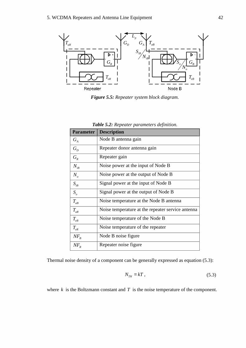
5. WCDMA Repeaters and Antenna Line Equipment 42
eBTeRT
aRT
RG
DG AG aBT
BG
iB
iB
SN
o
o
SN
pL
Figure 5.5: Repeater system block diagram.
Table 5.2: Repeater parameters definition.
Parameter Description
AG Node B antenna gain
DG Repeater donor antenna gain
RG Repeater gain
iBN Noise power at the input of Node B
oN Noise power at the output of Node B
iBS Signal power at the input of Node B
oS Signal power at the output of Node B
aBT Noise temperature at the Node B antenna
aRT Noise temperature at the repeater service antenna
eBT Noise temperature of the Node B
eRT Noise temperature of the repeater
BNF Node B noise figure
RNF Repeater noise figure
Thermal noise density of a component can be generally expressed as equation (5.3):
THN kT= , (5.3)
where k is the Boltzmann constant and T is the noise temperature of the component.
5. WCDMA Repeaters and Antenna Line Equipment 43
Using Figure 5.5, the total thermal noise contribution at Node B therefore becomes: ( ) ( )o aR eR T aB eBN k T T G k T T= + + + , (5.4)
where TG represents the total gains and losses on the link between repeater and Node B.
Mathematically:
T R D P AG G G L G= . (5.5)
The BEF in an unloaded network can now be defined by equation (5.6) as a relation of
SNR between the input and output at Node B. Mathematically:
( ) ( )
iB iB
iB aBB
o o
oaR eR T aB eB
S SN W kT
EFS S
N W k T T G k T T
⋅= =
⋅ + + +
. (5.6)
If W is the signal bandwidth and iB oS S= , the above equation can be further simplified
as:
B B T REF NF G NF= + ⋅ . (5.7)
5.4. Repeaters in UMTS Network
Repeaters have significant impact on both the coverage and to some extent on the capacity of a UMTS cell. Their deployment in UMTS is quite simple and undemanding when it comes to increasing the coverage. However in terms of capacity, it is not a very easy task because of the presence of inter-cell interference. As the whole band is amplified without signal regeneration, therefore interference from other UMTS users is also included in the amplification process and only out of band interference is filtered out. However, correctly configured repeater deployment can result in a significant gain in overall cell performance.
Repeater deployment in UMTS cell decreases effective path loss between Node B and UE (located in repeater service area) and increases the received signal level at UE relative to the interference. This enables Node B to reduce transmit power thus increasing downlink cell capacity. Moreover UE located in repeater service area can use lower transmit power in uplink thus minimizing inter-cell interference and enhancing uplink capacity.

5. WCDMA Repeaters and Antenna Line Equipment 44
When planning repeater installation; deployment location and used gain values are
critical because of noise and interference amplification behaviour of repeater. Smaller distance between donor Node B and repeater or high UL repeater gain value can have negative impact on donor Node B’s receiver sensitivity since repeater amplifier is not noiseless and contributes additional noise to the signal received by the donor Node B. The effects of repeater gain in different cell load situations must be addressed in the planning phase. Additionally, presence of repeater in UMTS cell requires link budget parameters to be recalculated for users under repeater service area largely because of
increased b oE N requirements and absence of diversity techniques available for
repeater connections. A repeater is transparent to the surrounding network i.e. the UMTS cell does not
recognize whether a repeater is present in its coverage area or not. Therefore power control algorithms function transparently through the repeater. Moreover, SHO is not applicable between the donor sector and the repeater service area since both belong to the same logical cell i.e. both transmits the same downlink signal with same scrambling code. From UE perspective, repeater signal is only an additional peak received in the delay profile of its RAKE receiver.
Multiple repeaters can be installed in a UMTS cell independently or cascaded.
However received noise at donor Node B is increased correspondingly and in chain deployment, the total delay and poor signal quality due to repeater noise contribution can limit the usefulness of repeater in a UMTS cell.
5.5. Repeater Utilization for Indoor Environments
As presented earlier, macro-cellular indoor coverage and dedicated indoor systems can be used to provide adequate or enhanced indoor coverage but at the expense of capacity limitation and high infrastructure cost. This thesis exploits outdoor repeater utilization as an alternative to dedicated indoor solution and uses an existing macro-cell to extend UMTS/HSDPA coverage indoors. This principle is known as so called outdoor-to-indoor repeating and is illustrated in Figure 5.6.
The signal from outdoor network is captured using a rooftop antenna and repeated inside the building using a single discrete antenna or passive DAS. The captured signal is amplified using the analogue repeater before retransmission, which not only helps in overcoming building penetration loss, but also significantly improves the signal coverage as well as quality in indoor environment as compared to macro-cell to indoor coverage.

5. WCDMA Repeaters and Antenna Line Equipment 45
Figure 5.6: Outdoor-to-indoor repeating.

6. Measurements 46
6. MEASUREMENTS
The HSDPA performance analysis is based on an extensive measurement campaign which was performed in typical indoor environments. This chapter describes the measurement network setup including parameters, antenna configuration & location and different measurement scenarios. Measurement results are presented afterwards followed by their in-depth analysis.
6.1. Measured Quality Indicators
Generally in DL, the coverage level of measured signal is analyzed in terms of received
signal code power ( RSCP) and received signal strength indicator ( RSSI). RSCP defines the absolute coverage level of P-CPICH (after de-spreading) that can be reached with different antenna configurations. Quality of measured signal (P-CPICH) is
characterized by received energy per chip over noise spectral density ( c oE N ) defined
as equation (6.1):
c o
RSCPE N
RSSI= , (6.1)
where RSSI is the total received power over the whole wideband channel. HSDPA system capacity is more realistically indicated by MAC layer throughput (TP). This TP corresponds to physical layer TP with approximately 5% overhead and is dependent on the channel quality monitored by CQI reports. CQI cannot be measured directly at radio interface since it is UE vendor specific calculation based on channel
measurements (RSCP, c oE N etc.). However, its influence on TP is considered a useful
indicator since Node B performs AMC based on mobile CQI reports.
In UL, the interference and noise level (ULi ) experienced by the Node B is an
important measure since it directly limits the repeater gain adjustment and affects UL system performance. This value is reported to UE in DL using broadcast channel (BCH).

6. Measurements 47
6.2. Measurement Setup
6.2.1. Network Configuration
Measurements were performed in a fully operational HSDPA (3GPP Release 5 specification [23]) enabled UMTS macro-cellular network supporting throughput up to 3.6 Mbps at physical layer and 3.52 Mbps at MAC layer. The outdoor mother cell included a RNC connected to a CN and a Node B with a directional antenna mounted at the height of a building rooftop. The indoor network was created using Outdoor-to-Indoor repeating principle that is by capturing the signal from the mother cell antenna via donor antenna and then repeating the signal inside the building using an analogue WCDMA repeater [24]. The signal from the repeater was further distributed by indoor distributed antenna system which is referred to as service antenna hereafter.
A detailed system block diagram of the network and antenna line components is presented in Figure 6.1. A typical macro-cell antenna with a half-power horizontal beamwidth of 65° and a gain of 17.1 dBi was selected as the repeater donor antenna. The antenna was installed on roof of the building as shown in Figure 6.3(a) and it was directed towards the best hearable sector of the mother cell at about 10° offset from mother cell antenna’s main beam direction thus ensuring that donor antenna was not pointing towards the SHO region. The mother cell antenna was located at a distance of approximately 450 meters and was in LOS from the location of donor antenna. However; a few obstacles for example some trees and rooftops were present inside the Fresnel zone of the effective link path as illustrated in Figure 6.2(b).
For reference repeater configuration, pilot RSCP difference with the neighbouring macro-cell, as measured at the repeater service antenna, was adjusted to be 10 dB that is:
_ 2 _ _ 10best cell nd best cellP RSCP RSCP dB∆ = − = . (6.2)
The donor antenna was connected to the analogue repeater using 78 inch coaxial
feeder cable. The repeater, with pre-selected gains varying in steps of 10 dB, was used to amplify the signal of wanted WCDMA frequency band from donor antenna in DL and from service antenna(s) in UL. The main parameters of repeater are listed in Table 6.1.
For indoor propagation of WCDMA/HSDPA signal, omni-directional antennas with a gain of 2 dBi were chosen as service antennas. Depending on the service antenna configuration, signal from the repeater was either transmitted directly to the service
antenna using a combination of 78 and 12 inch coaxial feeder cables (Figure 6.1 (a))

6. Measurements 48
or by adding a 1:3 splitter to this cable setup thus splitting the signal in equal parts for three service antennas (Figure 6.1 (b)).
Table 6.1: Repeater and donor antenna parameters.
Parameter Value
Repeater DL power (max.) 35 dBm
Repeater UL power (max.) 20 dBm
Repeater noise figure 3 dB
Repeater gain (min. – max.) 55 dB – 90 dB
Repeater donor antenna gain 17.1 dB
Donor antenna beamwidth 65°
RNCRepeater
HSDPA UENode B
Service
antennaMother
cell
antenna
Repeater
donor
antenna
35m
-2.5dB
60m
-10dB35m
-2.5dB
25m
-4.2dB
P-CPICH: 33dBm
+17.1dBi
+2dBiGain (dB):
55, 65, 75
(a) 1 service antenna
(b) 3 service antennas
Figure 6.1: Block diagram of indoor measurement network and antenna line.
6.2.2. Measurement Equipment and Software
The measurement equipment consisted of a category 5/6 HSDPA data card [20] with the parameters listed in Table 6.2. The data card was connected to a laptop computer equipped with Nemo outdoor field measurement software [22]. The measurement equipment was placed on a wheeled trolley approximately at a height of 1 meter, therefore without body effect.

6. Measurements 49
Table 6.2: Measurement UE / data card parameters.
Parameter Value
Max. bit rate 3.6 Mbps
Spreading Factor (SF) 16
Channel coding rate 34
Modulation 16QAM (4 bits/symbol) and QPSK (2 bits/symbol)
Channelization code(s) 5
6.3. Measurement Campaign
In order to study the performance of HSDPA network (Figure 6.1), an extensive measurement campaign was carried out in a typical multi-storied office building of Department of Information Technology, Tampere University of Technology in Finland. An overview of the building and relevant floor plans is presented in Figure 6.2(a), 6.3 and 6.4.
Three typical indoor environments: a large open area, a long wide open corridor, and a dense office corridor, analogous to easy, medium and hard propagation environments, were selected for the measurement campaign. The open area and open corridor had approximate room heights of 6 m while the open corridor was approximately 100 m long and 10 m wide. The approximate room height of dense office corridor was 2.5 m. One and three service antenna configuration (Figure 6.1) was respectively used to transmit HSDPA signal during measurement rounds in all environments. For open corridor and open area measurements, these antennas were placed with constant spacing on second floor footbridge at the height of 4.5 m. Therefore, LOS and wall reflected NLOS propagation paths were present between the antenna(s) and the measuring UE in these environments. For office corridor, the antenna(s) were placed on a second floor office corridor just above the corridor where measurements were done. Thus only NLOS propagation with one floor attenuation was available. Figure 6.3 (b) & (c) show antenna locations marked with cross signs for all measured indoor environments.
HSDPA traffic was created using hyper text transfer protocol (HTTP) file download from a server. In order to have measuring UE request full throughput (TP) for a single connection, off-peak hours were selected for the campaign. Thus network was empty
and no other traffic was present. This was further ensured by performing short c oE N
test measurements just below the service antenna(s) before starting each measurement round. The presence of other HSDPA traffic has a direct affect on the measured TP due

6. Measurements 50
to the shared nature of high speed DL data channel (HS-DSCH) which, naturally, will produce inaccurate data for analysis.
All measurement rounds were first made with repeater turned ON, one service
antenna configuration (Figure 6.1(a) and 6.3(b)), and by activating a HSDPA data connection and pushing the measuring UE trolley at walking speed through pre-defined routes. These routes are presented in Figure 6.4(a) with solid lines for all environment types. Open area measurements were repeated for a long route to evaluate HSDPA service availability for different distributions of indoor users. The long route is marked in Figure 6.4(a) as dashed lines. The only repeater parameter that was adjusted during each measurement round was repeater gain (Table 6.1) in steps of 10 dB. The pre-selected gain values, 55 dB, 65 dB and 75 dB, were chosen to study HSDPA performance in low gain to high gain operating areas of the repeater. For link symmetry, same gain values were used for both downlink and uplink. All these measurement rounds were then repeated by increasing the service antenna density i.e. with three service antennas (Figure 6.1(b) and 6.3(c)) over the same measurement routes (Figure 6.4(a)) and environments. Measurements were also done with repeater switched off i.e. HSDPA signal coming directly from the macro-cell was measured in all environments.
As a special case, measurements to analyze the effect of only NLOS propagation
path between service antenna(s) in open corridor (Figure 6.3 (b) and (c)) and measuring UE in office corridor (Figure 6.4(b)), were also performed. Such a scenario is quite possible in office buildings. Moreover, to analyze the effect of different possible service antenna positions, additional measurements were done in open area by re-positioning the service antennas to have total NLOS between them. The location of three service antennas used in this scenario is illustrated in Figure 6.3(c) where antenna marked in blue is moved to the location marked in green.
Furthermore, the impact of poor repeater installation or location in the network i.e.
when repeater is installed in SHO or SfHO region was also studied. Network configuration was slightly modified by mis-directing the repeater donor antenna from mother cell towards a neighbouring cell thus reducing P∆ to 0 dB. Afterwards, all repeater measurements for open corridor (LOS/NLOS and NLOS-only) were re-iterated for analysis.
For statistical reliability and to reduce measurement errors, each measurement round
with same configuration and route was repeated for 10 minutes.

6. Measurements 51
(a)
(b)
Figure 6.2: (a) Aerial photo of the used building. (b) Arial photo of the macro-cell area
and Fresnel zone [32].

6. Measurements 52
(a) 5th floor – repeater donor antenna at rooftop.
(b) 2nd floor – 1 repeater service antenna.
(c) 2nd floor – 3 repeater service antennas.
Figure 6.3: Antenna locations for HSDPA measurements.

6. Measurements 53
(a) 1st floor – measurement route(s).
(b) 2nd floor – measurement route.
Figure 6.4: Routes for HSDPA measurement campaign.

6. Measurements 54
6.4. Measurement Results
The results of HSDPA measurement campaign are tabulated in Appendix Table A. The numerical data represents averaged sample values of the quality indicators gathered during all measurements. Each environment and used repeater gain are categorized in row subsections while corresponding RSCP, Throughput, UL interference values etc. for 1 and 3 service antenna configurations are listed in columns. Macro-cellular values correspond to the repeater OFF measurements where signal from the mother cell was measured directly inside the building. The results from the Appendix Table A are further discussed for selected scenarios in the following sections.
6.4.1. Impact of Repeater Installation
Macro-cellular networks typically provide natural indoor coverage, therefore in addition to outdoor-to-indoor repeater network measurements; macro-cell indoor coverage (i.e. repeater OFF) was also measured for reference comparison. It was observed that continuous macro-cell indoor coverage was either not available or varied in different environments.
Table 6.3 shows that overall coverage was worst in dense/office corridor environment where, with measured average RSCP level of -119.1 dBm, no HSDPA TP was available. On the other hand, relatively better coverage was available in open area (avg. RSCP = -101.5 dBm) and open corridor (avg. RSCP = -104.3 dBm) offering modest average throughputs of 1.89 Mbps and 1.37 Mbps respectively. Clearly, only up to 50% of HSDPA TP is available with macro-cell coverage and that too in an easy or medium type of indoor environment. Therefore the need to improve HSDPA coverage inside the building was evident in order exploit HSDPA technology to its full and to better serve the needs of indoor users.
With the outdoor-to-indoor repeater network switched ON, significant improvement in HSDPA performance was observed. Figure 6.5 presents this improvement with average TP as a function of average RSCP for all environments. The data points joined with straight lines correspond to the averaged values (Table 6.3) measured with 55 dB, 65 dB and 75 dB repeater gains in each environment. For reference comparison, averaged values from the repeater OFF measurements are also marked for open corridor and open area. From Figure 6.5, it can be observed that RSCP is improving in line with the increasing repeater gain thus ensuring that the presence of repeater is not degrading the performance of the network in any way. As a result of this improved coverage, significant increase in HSDPA TP in all measured indoor environments is clearly evident from the figure.

6. Measurements 55
Table 6.3: Measurement results for all indoor environments with 3 DAS.
Repeater gain [dB]
RSCP [dBm]
c oE N
[dB]
Throughput [kbps]
Mean CQI
UL int. [dBm]
Open corridor measurements Macro-cellular -104.3 -10.7 1373 10.9 -105
55 dB -84.0 -11.0 2591 16.9 -105
65 dB -74.5 -10.8 2883 17.2 -104
75 dB -64.8 -10.3 3031 17.5 -100
Dense/office corridor measurements Macro-cellular -119.1 -17.6 N/A N/A -105
55 dB -97.8 -11.9 2225 15.8 -105
65 dB -88.7 -10.9 2974 18.0 -104
75 dB -78.0 -10.3 3001 18.4 -100
Open area measurements Macro-cellular -101.5 -13.3 1892 15.5 -105
55 dB -83.1 -11.0 2435 16.6 -105
65 dB -74.0 -11.0 2923 17.5 -104
75 dB -64.0 -10.7 3036 18.3 -100
-110 -105 -100 -95 -90 -85 -80 -75 -70 -65 -60
1500
2000
2500
3000
3500
Avg. RSCP [dBm]
Avg
. M
AC
Thr
ough
put
[kbp
s]
Open corridor: rep. off
Open corridor rep. on
Dense corridorOpen area: rep. off
Open area: rep. on
Figure 6.5: Avg. RSCP and Avg. MAC layer TP with 3 service antennas.
Already with a small repeater gain of 55 dB, an average improvement of 1.2 Mbps in TP can be observed in open corridor environment when compared with macro-cell indoor coverage. Similarly, in dense office corridor, an average TP of 2.2 Mbps is

6. Measurements 56
available which is quite significant provided that no TP was available during repeater OFF measurement. Open area measurement also shows an average improvement of 500 kbps in TP just by turning the repeater ON with 55 dB gain. Harsh propagation conditions in dense corridor scenario can most likely explain the starting difference of approx. 15 dB in terms of RSCP (Figure 6.5) as compared to open corridor and open area where the propagation conditions clearly seem to be better. Figure 6.5 illustrates that increasing the repeater gain to 65 dB shows further improvement in measured TP; reaching an average of 3 Mbps, which in fact is quite close to the theoretical maximum of 3.5 Mbps. With the repeater gain set to 75 dB, no significant increase in TP is seen and TP seems to saturate around 3 Mbps regardless of 10 dB rise in RSCP.
Evidently, HSDPA operation has benefited from the presence of repeater with improved coverage and close to maximum throughput available with high repeater gains (65 dB and 75 dB). Nevertheless, the impact of repeater on UL system performance can be observed from UL interference (noise rise) as listed in Table 6.3 and illustrated in Figure 6.6. The noise rise experienced by the mother cell comes from the amplified noise of the repeater in uplink. When compared with repeater OFF scenario, the effect of repeater gain 55 dB, which is measured to be -105 dBm, is not yet visible in UL interference. A small noise rise of 1 dB with repeater gain of 65 dB is measured, the effect of which is rather insignificant. However, UL interference increases significantly to -100 dBm when the repeater gain is set to 75 dB. This noise rise of 5 dB indicates a highly loaded cell with poor UL performance and capacity. It is important to mention that the mother cell-to-repeater configuration remains unchanged and therefore the results for UL interference (Table 6.3) exhibit the same the noise rise pattern for all environments and service antenna configurations.
-104
-99
-104
-100
-105-105-106
-104
-102
-100
-98
-96
Rep. Off 55 65 75
Repeater gain (dB)
UL
inte
rfer
ence
(d
Bm
)
RSCP diff = 0 dB
RSCP diff = 10 dB
Figure 6.6: UL noise rise as a function of repeater gain.

6. Measurements 57
It can also be seen from Table 6.3 how the behaviour of average throughput is
closely affected by the corresponding average reported CQI. This is characteristic to HSDPA since the decision to offer a TP (high or low or no) is based on instantaneous CQI value reported by UE. This CQI-throughput behaviour was closely observed during the actual measurements where higher CQI values resulted in higher AMC (16 QAM) thus generating higher TP. On the contrary, the average RSCP values (in Table 6.3) are not in line with the corresponding CQI values although CQI calculation is partly based on the channel measurements. The reason for this behaviour cannot be determined since vendor specific information regarding CQI calculation is unknown.
6.4.2. Impact of Indoor Environment
In order to statistically examine the effects of repeater deployment in indoor environments, cumulative distribution functions (CDF) of measured RSCP and throughput samples; for each environment, repeater gain and three service antenna configuration, are plotted in Figure 6.7 – 6.12. CDFs of repeater OFF measurements from open area and open corridor are also added to the plots for reference comparison.
From the RSCP CDFs of open corridor (Figure 6.7), it can be observed that with repeater OFF, measured RSCP varies between -120 dBm and -90 dBm. Already with a small repeater gain of 55 dB, an average increase of -20 dBm in RSCP is seen. CDF results of repeater ON show that almost all the RSCP samples are above -100 dBm while only 15% of the samples are above -100 dBm in case of repeater OFF measurement thus signalling a clear improvement in the coverage with the repeater network.
-130 -120 -110 -100 -90 -80 -70 -60 -50 -400
0.1
0.2
0.3
0.4
0.5
0.6
0.7
0.8
0.9
1
RSCP [dBm]
CD
F
Repeater off
GR = 55dB
GR = 65dB
GR = 75dB
Figure 6.7: RSCP CDF – Open corridor, 3 service antennas.

6. Measurements 58
Even though the repeater gain of 75 dB provides maximum coverage (RSCP level
above -80 dB), nevertheless considering the UL interference limitation set by this high repeater gain (rise up to 5 dB), the repeater gain of 65 dB seems to provide the same essential coverage 80% of the time and without deteriorating the UL performance. Thus significant improvement is seen in the coverage of open corridor in the presence of the repeater. Based on Figure 6.8, open area shows relatively better initial macro-coverage with approximately 30% samples above -100 dBm and, similar to open corridor scenario, nearly all measured RSCP samples with repeater ON lie above -100 dBm. Moreover, RSCP CDF curves for different repeater gains in open area seem to exhibit similar patterns as in open corridor therefore the conclusions drawn for open corridor can be held valid in this easy indoor environment as well.
-130 -120 -110 -100 -90 -80 -70 -60 -50 -400
0.1
0.2
0.3
0.4
0.5
0.6
0.7
0.8
0.9
1
RSCP [dBm]
CD
F
Repeater off
GR = 55dB
GR = 65dB
GR = 75dB
Figure 6.8: RSCP CDF – Open area, 3 service antennas.
Figure 6.9 shows the RSCP CDF of measurements done in dense corridor environment which is analogous to a typical office environment with hard propagation conditions. As listed in Table 6.3 and discussed in section 6.4.1; mother cell coverage was very discontinuous and poor (average RSCP -119 dBm) in this environment. Even with the repeater turned ON, some samples below -100 dBm are noticeable from Figure 6.9. The coverage improvement with repeater gain of 65 dB is considerable when compared with the macro-cell coverage but overall RSCP levels are lower than the other indoor environments due to added floor attenuation. However, the measurement results show that the average throughputs with different repeater gains are still reasonably high and match the TPs measured in other indoor environments. This behaviour is consistent with the HSDPA feature to efficiently exploit AMC for short TTI of 2 ms during better radio channel conditions.

6. Measurements 59
-130 -120 -110 -100 -90 -80 -70 -60 -50 -400
0.1
0.2
0.3
0.4
0.5
0.6
0.7
0.8
0.9
1
RSCP [dBm]
CD
F
Repeater off
GR = 55dB
GR = 65dB
GR = 75dB
Figure 6.9: RSCP CDF – Dense corridor, 3 service antennas.
Figure 6.10 presents the CDFs of throughput samples measured in open corridor. It can be observed that with the macro-cell coverage, on average, TP remains under 1.6 Mbps 70% of the times while TP levels up to 3 Mbps are also measured at certain locations. With a small repeater gain of 55 dB a decrease in number of low TP samples is seen instantly. It is also evident from the CDFs how the number of high TP samples increase steadily as the repeater gain is increased. Moreover, with repeater ON, maximum TP of 3.5 Mbps is also instantaneously recorded during the measurements in all environments with all repeater gains (Figure 6.10, 6.11 and 6.12).
In Figure 6.11, the CDF of throughput without repeater in open area shows a visible peak for samples between 1.5 and 1.7 Mbps. The most likely cause of such peak is the poor radio channel conditions where HSDPA network doesn’t exploit higher order modulation and coding schemes to its full during such weak instantaneous connections. On the contrary, presence of repeater in open area seems to increase the number of high TP samples efficiently. Hence, with a repeater gain of 65 dB yielding a TP above 3 Mbps 60% of the time, improvement in HSDPA performance is evident.

6. Measurements 60
0 500 1000 1500 2000 2500 3000 3500 40000
0.1
0.2
0.3
0.4
0.5
0.6
0.7
0.8
0.9
1
HSDPA MAC layer throughput [kbps]
CD
F
Repeater off
GR = 55dB
GR = 65dB
GR = 75dB
Figure 6.10: MAC TP CDF – Open corridor, 3 service antennas.
0 500 1000 1500 2000 2500 3000 3500 40000
0.1
0.2
0.3
0.4
0.5
0.6
0.7
0.8
0.9
1
HSDPA MAC layer throughput [kbps]
CD
F
Repeater off
GR = 55dB
GR = 65dB
GR = 75dB
Figure 6.11: MAC TP CDF – Open area, 3 service antennas.
The CDFs of Figure 6.12 illustrates the behaviour of throughput as measured with repeater in dense office corridor. No TP with coverage from macro-cell is measured while, with the repeater ON, TP levels up to 3.5 Mbps are achieved instantly. The CDF curve of an initial repeater gain of 55 dB shows an increase in low TP samples as compared to open corridor and open area. This is inline with the fact that such low repeater gain is not enough to avert the losses laid out by the harsh NLOS propagation

6. Measurements 61
and floor attenuation. With the repeater gain of 65 dB, TP CDF seems to follow a similar behaviour when compared with its counter parts in open area and open corridor. Moreover, the throughput CDF of repeater gain 75 dB seems to follow the CDF of 65 dB rather closely thus indicating a saturation. However, use of such a high gain is yet limited by the UL noise rise and therefore the repeater gain of 65 dB is sufficient to improve HSDPA performance considerably with a noise rise of just 1 dB (-105 dBm to -104 dBm).
0 500 1000 1500 2000 2500 3000 3500 40000
0.1
0.2
0.3
0.4
0.5
0.6
0.7
0.8
0.9
1
HSDPA MAC layer throughput [kbps]
CD
F
Repeater off
GR = 55dB
GR = 65dB
GR = 75dB
Figure 6.12: MAC TP CDF – Dense corridor, 3 service antennas.
6.4.3. Impact of Poor Repeater Installation
Thus far, the impact of repeater gain on HSDPA performance in indoor environments has shown quite promising results in terms of improved coverage and increased data rates. However, an optimized location of repeater deployment itself in the network is vital to exploit the performance to its maximum. As part of the measurement campaign, poor repeater installation in the network was studied by modifying the reference repeater donor to mother cell antenna orientation
( _ 2 _ _ 10best cell nd best cellP RSCP RSCP dB∆ = − = ). The antenna was mis-oriented towards a
neighbouring cell thus reducing 0P dB∆ = which is analogous to placing the repeater
in a SHO/SfHO area.
The results for measurements done in open corridor with poor repeater installation
are listed in Appendix Table A. Comparing the average results of 10P dB∆ = with
0P dB∆ = shows how HSDPA performance degrades significantly. Figure 6.13

6. Measurements 62
illustrates the impact of poor repeater installation with average TP as a function of average RSCP.
-110 -105 -100 -95 -90 -85 -80 -75 -70 -65 -601000
1500
2000
2500
3000
3500
Avg. RSCP [dBm]
Avg
. M
AC
Thr
ough
put
[kbp
s]
w/o Repeater
1 DAS w. Rep.: ∆P=10dB
1 DAS w. Rep.: ∆P=0dB
3 DAS w. Rep.: ∆P=10dB
3 DAS w. Rep.: ∆P=0dB
Figure 6.13: Avg. MAC layer TP as function of avg. RSCP (Open Corridor).
In case of repeater with 1 service antenna (dashed line vs. solid line), RSCP clearly drops between 5.9 dB and 7.1 dB while due to additional interference from the
neighbouring cell, c oE N also drops by 4 dB (Appendix Table A). Consequently the
throughput falls short between 321 kbps and 748 kbps as compared to the throughput achieved with optimal repeater donor antenna orientation. HSDPA performance with poor repeater deployment and 3 service antennas seem to suffer relatively more where throughput drops up to 1.5 Mbps with a reduction of 5.5 dB in RSCP.
UL interference results of 0P dB∆ = in Appendix Table A and illustrated by Figure
6.6 show that 1 dB is further lost in noise rise (-100 dBm to -99 dBm) with repeater gain of 75 dB which is inline with the additional interference caused by the other cell. Thus system performance degrade is evident with donor antenna mis-orientation.
The RSCP CDF comparison for optimal and poor repeater donor antenna orientation is presented in Figure 6.14. Comparing the two repeater scenarios for different repeater gains, RSCP seems to have reduced by 10% to 30% over the same measurement route thus considerably reducing the HSDPA throughput and cancelling out any performance gain that repeater would have provided. Therefore special consideration should be given to finding an advantageous location and orientation of the donor antenna.

6. Measurements 63
-130 -120 -110 -100 -90 -80 -70 -60 -50 -400
0.1
0.2
0.3
0.4
0.5
0.6
0.7
0.8
0.9
1
RSCP [dBm]
CD
F
Repeater off
GR = 55dB: ∆RSCP=10dB
GR = 55dB: ∆RSCP=0dB
GR = 65dB: ∆RSCP=10dB
GR = 65dB: ∆RSCP=0dB
GR = 75dB: ∆RSCP=10dB
GR = 75dB: ∆RSCP=0dB
Figure 6.14: RSCP CDF for 10P dB∆ = and 0P dB∆ = (1 DAS/Open Corridor/LOS).
6.4.4. Measurement Data Snapshots
A few examples of real measurement data in different environments are illustrated in Figures 6.15 – 6.20. All illustrations are actual snapshots taken from the measurement tool, measured for repeater off as well as repeater on and 3 antenna configuration. Each snapshot represents one round trip on the corresponding measurement route. Moreover, throughput samples are averaged for 200 ms and RSCP samples for 600 ms in all the snapshots.
The illustrations present an insight on how throughput and RSCP behaviour varies during the measurement route. Since the measurement tool provides approximately averaged statistics therefore absolute correlation between throughput and RSCP is not evident. This can be further explained by the fact that offered HSDPA throughput changes in every 2 ms TTI with the reported CQI which is formulated (at least) on the
basis of RSCP, c oE N and interference.
With indoor coverage from macro-cell in open corridor (Figure 6.15), RSCP varies
between -95 dBm and -112 dBm while throughput stays under 1.8 Mbps with occasional peaks touching 2.5 Mbps.

6. Measurements 64
Figure 6.15: Open corridor, macro-cellular coverage.
Just by installing a repeater and DAS network in open corridor, instantaneous throughput reaching the theoretical maximum of 3.5 Mbps can be seen with maximum RSCP of -64 dBm (Figure 6.16). This max RSCP level is measured around or under the antenna, while moving away from the antenna, RSCP conveniently drops up to -85 dBm. Nevertheless, the continuous fades in RSCP cause the average throughput to remain under 3 Mbps.
Figure 6.16: Open corridor, repeater gain 65 dB / 3 service antennas / ∆P = 10 dB.

6. Measurements 65
Figure 6.17 shows a snapshot of measurement done with poor repeater installation
in open corridor. It can be seen that the throughput has deteriorated significantly even though similar RSCP values (when compared with Figure 6.16) are instantaneously measured in this scenario. This is characteristic to HSDPA operation when lower CQI values are formulated because of inter-cell interference thus effecting offered throughput. The overall throughput remains well under 1.8 Mbps while RSCP drops up to -95 dBm which implies that poor deployment of repeater does not provided any significant improvement to HSDPA operation.
Figure 6.17: Open corridor, repeater gain 65 dB / 3 service antennas / ∆P = 0 dB.
Measurement example for dense corridor with repeater is shown in Figure 6.18. Throughput peaks repeatedly tend to reach the maximum close to the antennas. However, frequent fades in radio channel quality prevents HSDPA throughput to remain at the maximum level. Furthermore, it can be observed from Figure 6.18 that relatively lower RSCP values of -76 dBm or below is providing peak throughput of 3.5 Mbps in dense corridor as compared to open corridor (Figure 6.16) where RSCP of -64 dBm was needed.
Finally, snapshots of open area macro-cell measurement and with repeater configuration are shown in Figure 6.19 and 6.20 respectively to further illustrate how RSCP and throughput varied in rather easy indoor propagation environment.

6. Measurements 66
Figure 6.18: Dense/office corridor, repeater gain 65 dB / 3 service antennas.
Figure 6.19: Open area, macro-cellular coverage.
Figure 6.20: Open area, repeater gain 65 dB / 3 service antenna / short route.

6. Measurements 67
6.5. Network Planning Guidelines
This section attempts to provide basic coverage planning guidelines to improve indoor HSDPA performance with the help of a repeater. The guidelines are based on the average measurement results presented in this thesis
Overall, a successful repeater configuration can effectively provide peak HSDPA performance as good as a dedicated indoor solution; studied in [13, 27, 28]. Ensuring adequate coverage and improved SINR is the key to maximum HSDPA throughput. Increasing the repeater gain may always improve the coverage (RSCP) but throughput may not necessarily improve inline with RSCP. The target should be to improve the overall channel conditions so that better channel quality indicator (CQI) values are generated and reported thus enabling Node B to use higher-order modulation (16 QAM) and reduced coding, consequently leading to the highest throughput level.
From coverage threshold planning point of view, RSCP of -105 dBm can provide an
average throughput above 1 Mbps. Coverage improvement up to 30 dB (until approximately -74 dBm) can produce HSDPA throughput between 2.5 Mbps (500 kbps per code) and 3 Mbps (600 kbps per code). Coverage improvement beyond that level doesn’t offer significant throughput increase although some improvement of few 100 kbps is available. However, the coverage planning threshold may differ in different indoor propagation environment and may also vary if different power allocations are used for HSDPA channel.
Selection of optimal repeater gain is typically a trade off between macro-cell and repeater service area performance. High repeater gain certainly increases the indoor coverage level; nevertheless, it amplifies the noise and interference in UL thereby limiting macro-cell performance and UL system capacity. Furthermore, finding an optimal repeater donor antenna site and orientation is imperative for successful repeater operation. Hence, special attention should be given to correct repeater parameters configuration and deployment location in the network, otherwise repeater can introduce critical performance problems in the macro-cell.
Finally, as verified by the results in this thesis and references [30, 31], coverage
quality and efficiency can be improved effectively by increasing the number of antennas in serving DAS which can provide added capacity.

6. Measurements 68
6.6. Error Analysis
The results of this thesis attempt to provide an approximation of a real HSDPA network in typical indoor environments. Nevertheless, HSDPA performance is really dependent on exact radio channel conditions of the actual indoor area to be planned and may vary significantly due to the building structure, construction material and obstacles in the surrounding area of transmitter and receiver.
Moreover, the accuracy of results may be affected partly by the measurement process itself; from network and measurement equipment setup to selection of measurement routes to samples collection and pre-processing of the samples. The measurement campaign for this research lasted for several days which imply that the actual repeater equipment (excluding donor antenna) and indoor DAS components were assembled and dismantled for every sprint. Since the network setup involved a lot of cabling and connectors, thus exact setup may have differed slightly. Nevertheless, the
accuracy of network setup was verified by doing short c oE N measurements before
each sprint. Selecting measurement routes and collecting adequate amount of samples over the study area has a significant impact on the validity of results.
In order to cover possible dynamic effects of the indoor radio channel and to increase the reliability of the results, each measurement route in easy, medium, hard propagation environment was repeated for 10 minutes. Furthermore, to increase the accuracy of results, sample pre-processing was done by removing few deep fade samples from the beginning and end of measurement data. These deep fade samples result from the rapid rise and drop of the measured parameters when measurement is started and stopped.
The HSDPA data card, used for measurements, was calibrated for commercial use therefore absolute values of radio channel measurements may include some inaccuracy. Consequently, the analysis of results done in this document is primarily based on the relative comparison of the measured scenarios.

69
7. CONCLUSIONS
Number of mobile broadband users are increasing at an accelerated pace and in the current competitive cellular market, extensive coverage, capacity and quality of service have become key factors in increasing end-user base. Earlier, the focus on indoor network planning was rather limited. Nevertheless, with more and more users enjoying multimedia services via HSDPA, typically inside the buildings, operators get a business opportunity they can profit from by improving their network’s indoor performance.
The main purpose of this thesis was to study outdoor-to-indoor repeater with indoor DAS as a deployment strategy to enhance and optimize HSDPA performance: coverage and throughput (capacity) in typical indoor environments. Furthermore, provide deployment guidelines for network planners and identify optimal configurations linked to WCDMA repeater and distributed antenna systems. The study was based on extensive HSDPA measurement campaign with and without repeater as part of the network topology. HSDPA signal was captured from macro-cell and repeated (via analogue WCDMA repeater) inside the building using 1 and 3 omni-directional antenna(s). Three typical indoor environments: open area, open corridor and dense office corridor were measured to evaluate HSDPA performance with the repeater network. Repeater gains of 55, 65 and 75 dB were used to include the effects of low to high gain repeater operating area.
Initial macro-cell coverage in all of the measured indoor locations was inadequate and thus clear need for a dedicated solution was present to support optimal HSDPA operation. By deploying an inexpensive outdoor-to-indoor repeater solution, coverage in the indoor locations was found to have improved significantly. The measurement results show that repeater can be very effective in enhancing the overall performance of HSDPA in indoor locations when indoor traffic is served by repeater service area. Already the lowest repeater gain (55 dB) noticeably improved coverage and throughput while peak performance was evident with high repeater gain (75 dB). Nonetheless, uplink interference, as detected by macro-cell Node B, was found to have increased from -105 dBm to -100 dBm with the use of high repeater gain in all environments. On average, repeater gain of 65 dB provided impressive overall coverage improvement up to 30 dB and throughput improvement up to 1 Mbps, 1.5 Mbps and 3 Mbps in open area, open corridor and dense corridor – and that too with a noise rise of just 1 dB. Thus optimal repeater gain was found to be a compromise between repeater service area performance and macro-cell performance.

70
The measurement results show that when coverage (RSCP) was raised to an
adequate level, maximum HSDPA throughput was achieved. However, these RSCP levels were found to be different for different indoor locations. In dense corridor, much lower average RSCP level (-89 dBm) was required as compared to open corridor (-74.5 dBm) and open area (-74 dBm) to achieve maximum average throughput of 3 Mbps. Moreover, average throughput was seen not to be following the average RSCP in all the measured locations. On the other hand, throughput was found to follow the behaviour of reported average CQI values rather closely. Nonetheless, CQI calculation was evidently affected by other (unknown) factors in addition to radio channel quality parameters
( c oE N , RSCP). Furthermore, it was found that increasing the service antenna density
(from 1 to 3 antennas) in distributed antenna system had a clear positive impact on the SIR and consequently HSDPA coverage and capacity was further improved. Finally, the measurement results confirm that HSDPA indoor performance was significantly reduced when repeater donor antenna was mis-oriented away from the mother cell thereby placing the repeater in a SHO region.

71
REFERENCES [1] H. Holma, A. Toskala, WCDMA for UMTS, J. Wiley & Sons Ltd., 2007.
[2] J. Lempiäinen, M. Manninen, UMTS Radio Network Planning, Optimization
and QoS Management, Kluwer Academic Publishers, 2003.
[3] J. Korhonen, Introduction to 3G Mobile Communications, Artech House Incorporated, 2003.
[4] Mobile Evolution: shaping the future, A white paper by UMTS forum, [www]: http://www.umts-forum.org/.
[5] B. Walke, P. Seidenberg, M. P. Althoff, UMTS: The Fundamentals, J. Wiley & Sons Ltd., 2002.
[6] 3GPP TS 25.401, UTRAN overall description (Release 5), v. 5.9.0.
[7] J.D. Parsons. The Mobile Radio Propagation Channel. Pentech Press Ltd, 1992.
[8] P. Lähdekorpi, Effects of Repeaters on UMTS Network Performance, Master of Science Thesis, Tampere University of Technology, 2006.
[9] 3GPP TS 25.301, UMTS radio interface protocol architecture (Release 5), v. 5.6.0.
[10] J. Lempiäinen, M. Manninen, Radio Interface System Planning for
GSM/GPRS/UMTS, Kluwer Academic Publishers, 2001.
[11] S. Saunders, Antennas and Propagation for Wireless Communication
Systems, J. Wiley & Sons Ltd.
[12] H. Hashemi, The Indoor Radio Propagation Channel, in IEEE Transactions on Vehicular Technology Conference, Vol. 81, Issue 7, pp. 943-968, July 1993.
[13] T. Isotalo, J. Lempiäinen, J. Niemelä, Indoor Planning for High Speed
Downlink Packet Access in WCDMA Cellular Network, in Wireless Personal Communications Journal, June 2008.

72
[14] 3GPP TR 25.951, UMTS; FDD Base Station Classification (Release 7), v. 7.0.0.
[15] A. R. Mishra, Fundamentals of Cellular Network Planning and
Optimisation: 2G/2.5G/3G- Evolution To 4G, J. Wiley & Sons Ltd., 2007.
[16] 3GPP TS 25.201, UMTS; Physical layer - general description (Release 5), v. 5.3.0.
[17] H. Holma, A. Toskala, HSDPA/HSUPA for UMTS, J. Wiley & Sons Ltd., 2006.
[18] E. Dahlman, S. Parkvall, J. Sköld, P. Beming, 3G Evolution: HSPA and LTE
for Mobile Broadband, Elsevier Ltd., 2007.
[19] 3GPP TS 25.855, High Speed Downlink Packet Access (HSDPA); Overall
UTRAN description (Release 5), v. 5.7.0.
[20] 3GPP TS25.306, UE Radio Access Capabilities (Release 5), version 5.9.0.
[21] HSDPA: WCDMA Evolution, IEEE Vehicular Society News white paper.
[22] Anite Nemo Outdoor, Product Description, [www]: http://www.anite.com/nemo.
[23] 3GPP TS 25.308, High Speed Downlink Packet Access (HSDPA); Overall
description; Stage 2 (Release 5), v. 5.7.0.
[24] WCDMA Channel Selective Repeater: “AR6560”, Powerwave Technologies.
[25] T. Isotalo, J. Niemelä, J. Borkowski, J. Lempiäinen, Antenna Configuration
in WCDMA Indoor Network, in Proceedings of IST Mobile Summit, June 2006.
[26] M. Tolstrup, Indoor Radio Planning: A practical guide for GSM, DCS,
UMTS and HSPA, J. Wiley & Sons Ltd., 2008.
[27] K. Hiltunen, A Study of WCDMA Indoor Coverage and Capacity, Licentiate of Technology Thesis, Helsinki University of Technology, 2005.
73
[28] T. Isotalo, P. Lähdekorpi , J. Lempiäinen, Improving HSDPA Indoor
Coverage and TP by Repeater and Dedicated Indoor System, in EURASIP Journal on Wireless Communications and Networking, 2008.
[29] P. Lähdekorpi, T. Isotalo, A. Mazhar, J. Lempiäinen, Improving HSDPA
Indoor Performance Using Outdoor Repeater, in Proceedings of 11th Int. Symposium on Wireless Personal Multimedia Communications (WPMC’08), 2008.
[30] T. Isotalo, J. Lempiäinen, HSDPA Measurements for Indoor DAS, in 65th IEEE Vehicular Technology Conference, (VTC 2005), 2005.
[31] J. Borkowski, J. Niemelä, T. Isotalo, P. Lähdekorpi, J. Lempiäinen, Utilization of an Indoor DAS for Repeater Deployment in WCDMA, in 63rd IEEE Vehicular Technology Conference, (VTC 2006), 2006.
[32] Arial view, [www]: http://maps.live.com/.

74
APPENDIX
Tab
le A
: H
SD
PA
mea
sure
men
t re
sults
fo
r a
ll in
do
or
en
viro
nm
en
ts