Embed Size (px)
Citation preview

Alignment of DB and MB quadrupoles
Hélène MAINAUD DURAND
17/11/2011
With a lot of input from Sylvain GRIFFET

Outline
Actual plan
Case of MB quad and DB quad
Means
Proposals and questions
3
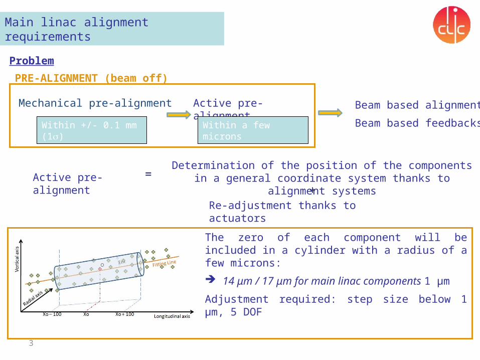
Main linac alignment requirements
Problem
Within +/- 0.1 mm (1s)
Active pre-alignment Beam based alignment
Beam based feedbacksWithin a few microns
Active pre-alignment
=Determination of the position of the components in a
general coordinate system thanks to alignment systems
Re-adjustment thanks to actuators+
The zero of each component will be included in a cylinder with a radius of a few microns:
14 μm / 17 μm for main linac components 1 µm
Adjustment required: step size below 1 µm, 5 DOF
Mechanical pre-alignment
PRE-ALIGNMENT (beam off)
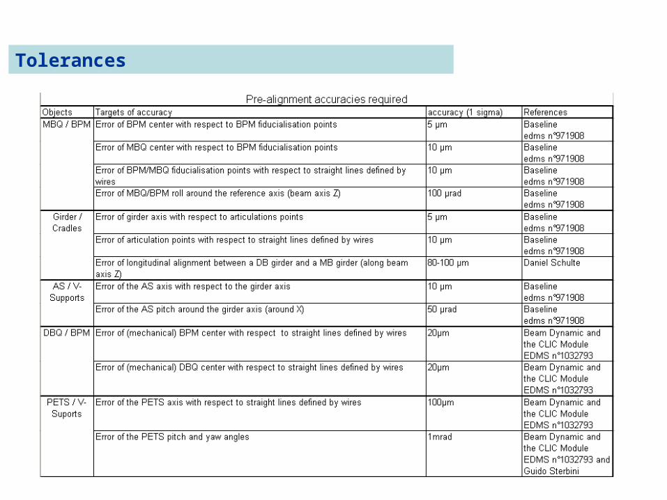
Tolerances
5
Alignment strategy
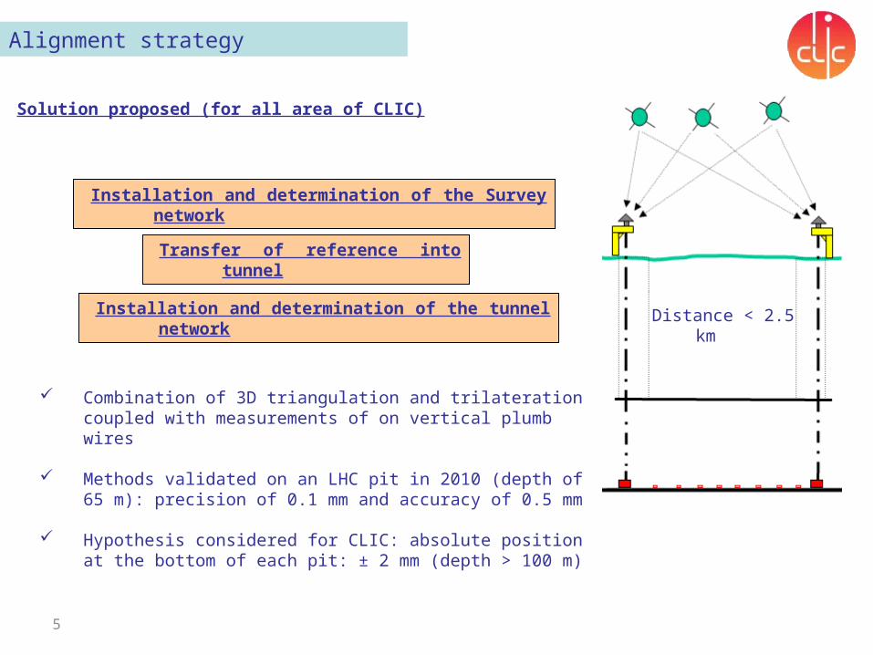
Solution proposed (for all area of CLIC)
Installation and determination of the Survey network
Transfer of reference into tunnel
Installation and determination of the tunnel network
Combination of 3D triangulation and trilateration coupled with measurements of on vertical plumb wires
Methods validated on an LHC pit in 2010 (depth of 65 m): precision of 0.1 mm and accuracy of 0.5 mm
Hypothesis considered for CLIC: absolute position at the bottom of each pit: ± 2 mm (depth > 100 m)
Distance < 2.5 km
6
BDS: strategy
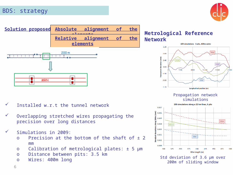
Solution proposed Absolute alignment of the elements
Relative alignment of the elements
Metrological Reference Network
Installed w.r.t the tunnel network
Overlapping stretched wires propagating the precision over long distances
Simulations in 2009: o Precision at the bottom of the shaft of ± 2 mmo Calibration of metrological plates: ± 5 μmo Distance between pits: 3.5 kmo Wires: 400m long
Std deviation of 3.6 μm over 200m of sliding window
Propagation network simulations
7
Alignment strategy
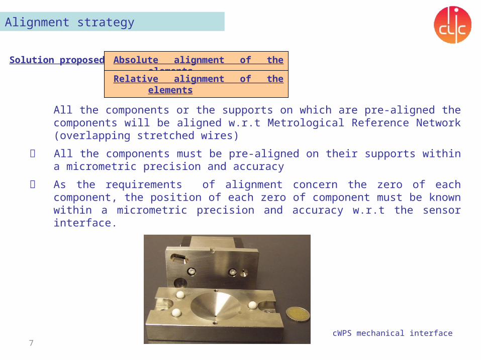
Solution proposed Absolute alignment of the elements
Relative alignment of the elements
All the components or the supports on which are pre-aligned the components will be aligned w.r.t Metrological Reference Network (overlapping stretched wires)
All the components must be pre-aligned on their supports within a micrometric precision and accuracy
As the requirements of alignment concern the zero of each component, the position of each zero of component must be known within a micrometric precision and accuracy w.r.t the sensor interface.
Laser tracker: AT 401
cWPS mechanical interface
8
Alignment strategy
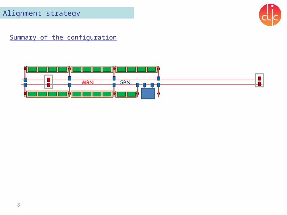
Summary of the configuration
9
Alignment strategy
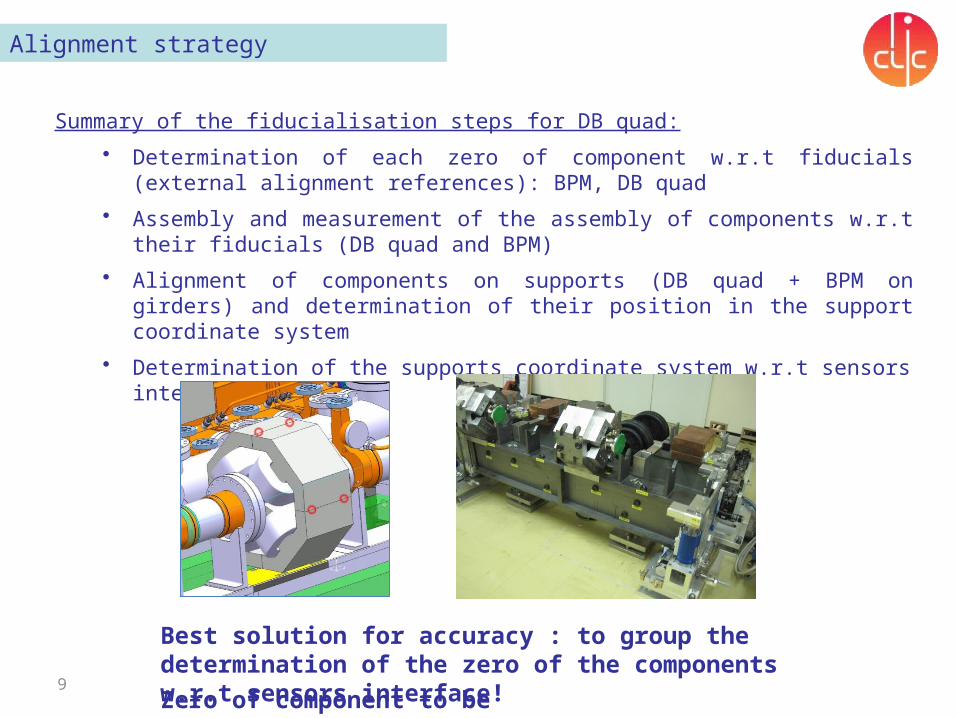
Summary of the fiducialisation steps for DB quad:
• Determination of each zero of component w.r.t fiducials (external alignment references): BPM, DB quad
• Assembly and measurement of the assembly of components w.r.t their fiducials (DB quad and BPM)
• Alignment of components on supports (DB quad + BPM on girders) and determination of their position in the support coordinate system
• Determination of the supports coordinate system w.r.t sensors interface
Best solution for accuracy : to group the determination of the zero of the components w.r.t sensors interface!
Zero of component to be precised.
10
Alignment strategy
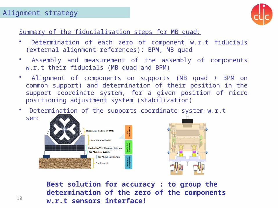
Summary of the fiducialisation steps for MB quad:
• Determination of each zero of component w.r.t fiducials (external alignment references): BPM, MB quad
• Assembly and measurement of the assembly of components w.r.t their fiducials (MB quad and BPM)
• Alignment of components on supports (MB quad + BPM on common support) and determination of their position in the support coordinate system, for a given position of micro positioning adjustment system (stabilization)
• Determination of the supports coordinate system w.r.t sensors interface
Best solution for accuracy : to group the determination of the zero of the components w.r.t sensors interface!
11
Alignment strategy
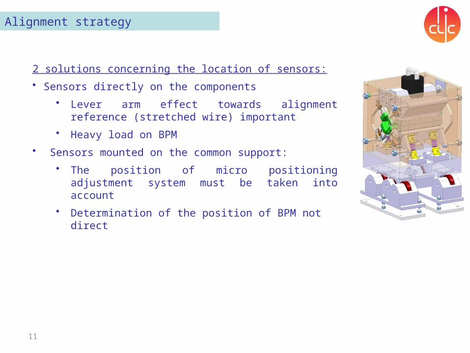
2 solutions concerning the location of sensors:
• Sensors directly on the components
• Lever arm effect towards alignment reference (stretched wire) important
• Heavy load on BPM
• Sensors mounted on the common support:
• The position of micro positioning adjustment system must be taken into account
• Determination of the position of BPM not direct
Means
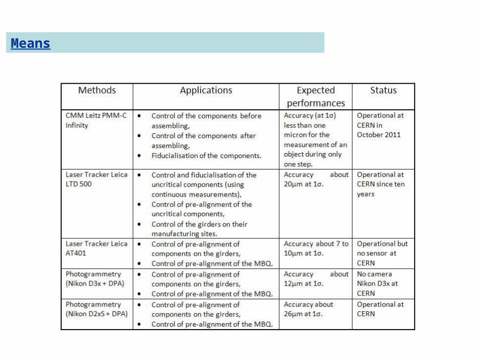
Means
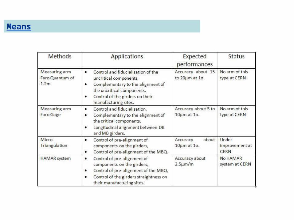
Means
15
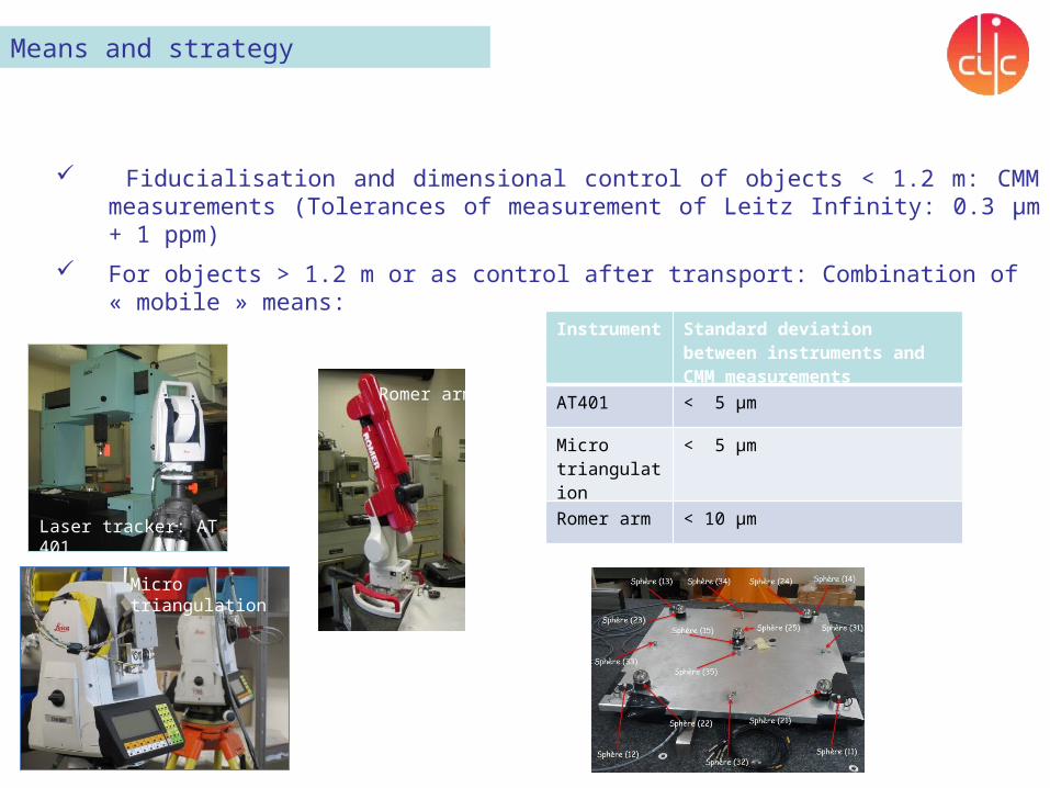
Means and strategy
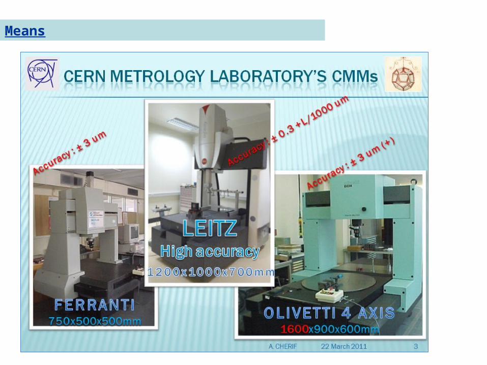
Fiducialisation and dimensional control of objects < 1.2 m: CMM measurements (Tolerances of measurement of Leitz Infinity: 0.3 μm + 1 ppm)
For objects > 1.2 m or as control after transport: Combination of « mobile » means:
Laser tracker: AT 401
Micro triangulation
Instrument
Standard deviation between instruments and CMM measurements
AT401 < 5 μm
Micro triangulation
< 5 μm
Romer arm < 10 μm
Romer arm
16
Some ideas…
Objective: the most precise and accurate measurement between the zero of the component and the sensors interfaces.
Perform the measurement of the magnetic axis of DB quad and MB quad in a CMM
If a “vibrating stretched wire” technique is used to perform the magnetic measurements, measure the position of this wire thanks to oWPS and cWPS. Then their mechanical interfaces and the mechanical interfaces of the alignment sensors can be determined through very accurate CMM measurements.
For the DB quad, use WPS mounted on supports installed on the V-shaped supports.
17
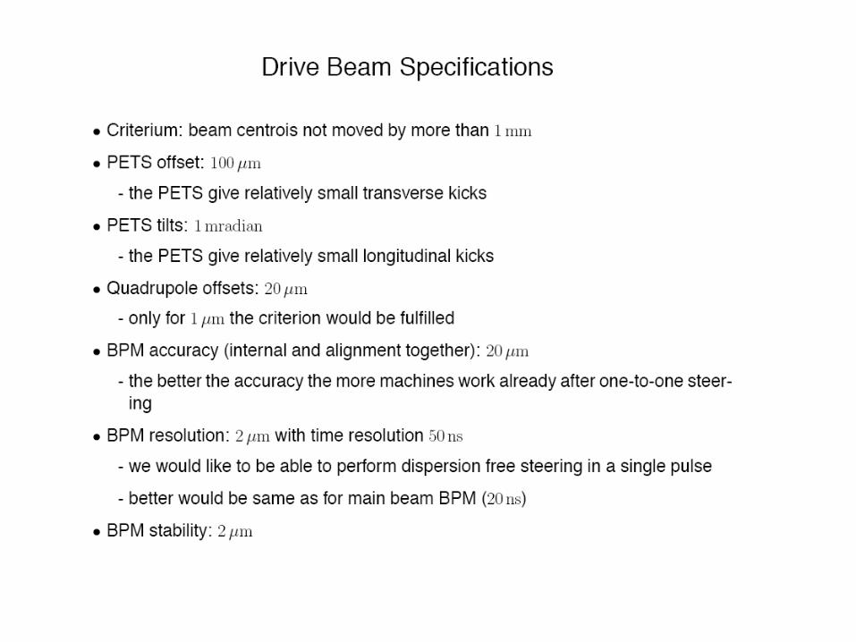
Some questions…
Definition of the zero of the components
Case of the MB quad: according to the requirements, the position of BPM should be known more precisely and accurately than the MB quad: 2 configurations to be studied
Clear definition of the tolerances needed:
what does “quadrupole offsets: 20 µm” mean?
Kinematic pitch problem raised by Kurt:
For the type 1: for a pitch with vertical delta of 1 mm, φ=0.38°
- longitudinal displacement of the center of ~ 2.5 mm
- vertical displacement ~ 8 µm

Thank you very much!