Embed Size (px)
Citation preview
Alignment of high-aspect ratio colloidal gold nanoplatelets in nematicliquid crystals
Julian S. Evans, Corinne N. Beier, and Ivan I. Smalyukha)
Department of Physics, Renewable & Sustainable Energy Institute, and Liquid Crystal MaterialsResearch Center, University of Colorado, Boulder, Colorado 80309, USA
(Received 20 March 2011; accepted 27 June 2011; published online 12 August 2011)
We study elasticity-mediated alignment of anisotropic gold colloids in liquid crystals. Colloidal gold
particles of controlled shapes (spheres, rods, and polygonal platelets) and sizes are prepared using
well-established biosynthesis techniques with varying solvent conditions. When introduced into
liquid crystalline structured solvents, these gold particles impose tangential or vertical surface
boundary conditions for the liquid crystal molecules or building blocks such as chromonic molecular
aggregates. This allows for multiple types of their controlled alignment in both lyotropic and
thermotropic liquid crystals and is of interest for self-assembly-based fabrication of tunable
nanostructured composite materials.VC 2011 American Institute of Physics. [doi:10.1063/1.3620550]
I. INTRODUCTION
Composite materials comprised of nano-sized and
micro-sized colloidal particle dispersions in structured host
media have attracted a great amount of interest.1–10 The plas-
monic properties of noble metallic particles make them de-
sirable structural units of a number of novel composites such
as optical metamaterials.11–14 In these artificial materials,
which are also often referred to as “left-handed materi-
als,”11–14 ordered structures of predesigned anisotropic nano-
particles play the role of ‘‘building blocks,” similar to that of
molecules and atoms in conventional matter,13 allowing for
the engineering of unprecedented properties not encountered
in naturally occurring materials,14 such as negative refractive
index. Control of the particle shape and size is essential for
engineering the needed surface plasmon resonance properties
for the development of optical and near-infrared metamateri-
als. The synthesis of functionalized spheres through thiol
linkages,15 the seed-mediated growth of nanorods,16 and a
variety of polyhedral and platelet-shaped17 particle syntheses
are well understood and broadly used, although obtaining
micro-sized gold colloids through conventional wet chemical
synthesis is limited by the high density of gold (causing sedi-
mentation of larger particles due to gravity) and is rarely
accomplished.15–21 Previous studies have shown that aque-
ous solutions of a variety of polyol containing biological
materials such as aloe vera extract,18 bovine serum albu-
min,19 lemon grass extract,20 and cellulose21 provide effec-
tive means for obtaining gold triangular platelets of various
lateral sizes and thicknesses. The post-synthetic manipula-
tion of morphology has been previously described in the con-
text of a many-particle to one-particle transformation
through lengthy refluxing.22 However, the potential uses of
biosynthesized gold nanoparticles to form tunable and recon-
figurable nanostructured composites have not been explored.
This is despite the fact that they are of particular interest for
such applications because of the simplicity of synthesis and
the feasibility of obtaining nanoparticles with a broad range
of controlled shapes and sizes.
In this work, we report dispersion of high-aspect ratio
biosynthesized gold platelets in both thermotropic and lyo-
tropic liquid crystals (LCs). We manipulate the particles’
shapes and sizes through redispersion in different solvents
and show that the gold platelet particles can impose both
tangential and vertical surface boundary conditions for the
liquid crystalline molecular alignment. This allows for sev-
eral different types of elasticity-mediated self-alignment of
polygonal gold platelets in LC host fluids, which are of inter-
est and importance for both fundamental and applied
research on LC colloidal dispersions.
II. MATERIALS AND METHODS
A. Preparation of gold nanoparticles
A typical gold particle synthesis was performed by dis-
solving 3.9 mg of gold(III) chloride hydrate in 9 mL of the
solvent, adding 1 mL of aqueous aloe vera extract solution,
and leaving the mixture at room temperature overnight. Aloe
vera extract was prepared by finely cutting 30 g of a 2 lb
aloe vera leaf (obtained from Aloe Farms, Inc.) and boiling it
in 100 mL of de-ionized water. According to previous stud-
ies, the reductant necessary for the nanoparticle synthesis is
likely a hydrophilic aldose, or aldehyde, or ketone present in
aloe vera.17 The solvents used and the gold(III) chloride
hydrate were obtained from Sigma Aldrich and used without
further purification except for the de-ionized water which
was obtained from the Barnstead/Thermolyne E-pure system
(>17 MX cm).
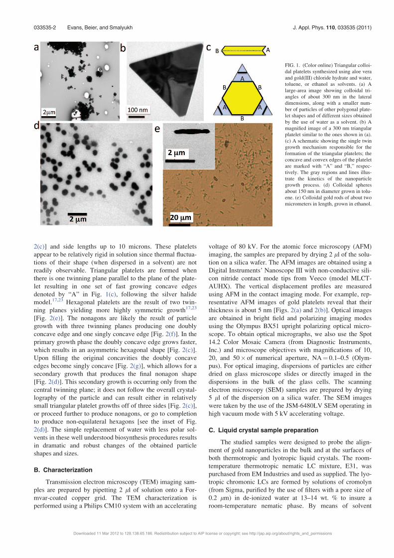
During the nanoparticle synthesis, we used water as the
solvent to produce 300 nm� 5 nm triangles and hexagons
[Figs. 1(a) and 1(b)], following the procedure previously
reported by Sastry et al.18,20 Using toluene instead of water
produces 150 nm spheres [Fig. 1(d)] and using ethanol pro-
duces 2 lm by 300 nm rods [Fig. 1(e)]. Using methanol as
the solvent produces highly polydisperse triangles, hexagons,
and nonagons [Fig. 2(a)] with 5 nm thickness [Figs. 2(b) anda)Electronic mail: [email protected].
0021-8979/2011/110(3)/033535/7/$30.00 VC 2011 American Institute of Physics110, 033535-1
JOURNAL OF APPLIED PHYSICS 110, 033535 (2011)
Downloaded 11 Mar 2012 to 128.138.65.186. Redistribution subject to AIP license or copyright; see http://jap.aip.org/about/rights_and_permissions
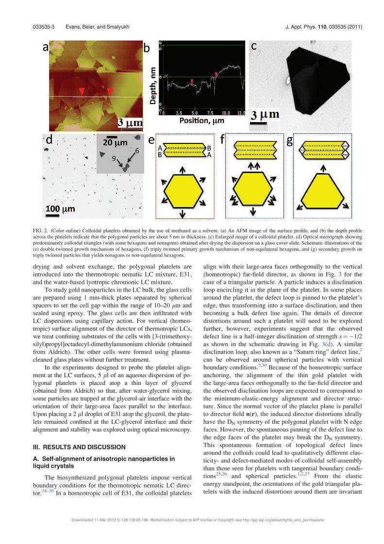
2(c)] and side lengths up to 10 microns. These platelets
appear to be relatively rigid in solution since thermal fluctua-
tions of their shape (when dispersed in a solvent) are not
readily observable. Triangular platelets are formed when
there is one twinning plane parallel to the plane of the plate-
let resulting in one set of fast growing concave edges
denoted by “A” in Fig. 1(c), following the silver halide
model.17,23 Hexagonal platelets are the result of two twin-
ning planes yielding more highly symmetric growth17,23
[Fig. 2(e)]. The nonagons are likely the result of particle
growth with three twinning planes producing one doubly
concave edge and one singly concave edge [Fig. 2(f)]. In the
primary growth phase the doubly concave edge grows faster,
which results in an asymmetric hexagonal shape [Fig. 2(c)].
Upon filling the original concavities the doubly concave
edges become singly concave [Fig. 2(g)], which allows for a
secondary growth that produces the final nonagon shape
[Fig. 2(d)]. This secondary growth is occurring only from the
central twinning plane; it does not follow the overall crystal-
lography of the particle and can result either in relatively
small triangular platelet growths off of three sides [Fig. 2(c)],
or proceed further to produce nonagons, or go to completion
to produce non-equilateral hexagons [see the inset of Fig.
2(d)]. The simple replacement of water with less polar sol-
vents in these well understood biosynthesis procedures results
in dramatic and robust changes of the obtained particle
shapes and sizes.
B. Characterization
Transmission electron microscopy (TEM) imaging sam-
ples are prepared by pipetting 2 ll of solution onto a For-
mvar-coated copper grid. The TEM characterization is
performed using a Philips CM10 system with an accelerating
voltage of 80 kV. For the atomic force microscopy (AFM)
imaging, the samples are prepared by drying 2 ll of the solu-
tion on a silica wafer. The AFM images are obtained using a
Digital Instruments’ Nanoscope III with non-conductive sili-
con nitride contact mode tips from Veeco (model MLCT-
AUHX). The vertical displacement profiles are measured
using AFM in the contact imaging mode. For example, rep-
resentative AFM images of gold platelets reveal that their
thickness is about 5 nm [Figs. 2(a) and 2(b)]. Optical images
are obtained in bright field and polarizing imaging modes
using the Olympus BX51 upright polarizing optical micro-
scope. To obtain optical micrographs, we also use the Spot
14.2 Color Mosaic Camera (from Diagnostic Instruments,
Inc.) and microscope objectives with magnifications of 10,
20, and 50� of numerical aperture, NA¼ 0.1–0.5 (Olym-
pus). For optical imaging, dispersions of particles are either
dried on glass microscope slides or directly imaged in the
dispersions in the bulk of the glass cells. The scanning
electron microscopy (SEM) samples are prepared by drying
5 ll of the dispersion on a silica wafer. The SEM images
were taken by the use of the JSM-6480LV SEM operating in
high vacuum mode with 5 kV accelerating voltage.
C. Liquid crystal sample preparation
The studied samples were designed to probe the align-
ment of gold nanoparticles in the bulk and at the surfaces of
both thermotropic and lyotropic liquid crystals. The room-
temperature thermotropic nematic LC mixture, E31, was
purchased from EM Industries and used as supplied. The lyo-
tropic chromonic LCs are formed by solutions of cromolyn
(from Sigma, purified by the use of filters with a pore size of
0.2 lm) in de-ionized water at 13–14 wt. % to insure a
room-temperature nematic phase. By means of solvent
FIG. 1. (Color online) Triangular colloi-
dal platelets synthesized using aloe vera
and gold(III) chloride hydrate and water,
toluene, or ethanol as solvents. (a) A
large-area image showing colloidal tri-
angles of about 300 nm in the lateral
dimensions, along with a smaller num-
ber of particles of other polygonal plate-
let shapes and of different sizes obtained
by the use of water as a solvent. (b) A
magnified image of a 300 nm triangular
platelet similar to the ones shown in (a).
(c) A schematic showing the single twin
growth mechanism responsible for the
formation of the triangular platelets; the
concave and convex edges of the platelet
are marked with “A” and “B,” respec-
tively. The gray regions and lines illus-
trate the kinetics of the nanoparticle
growth process. (d) Colloidal spheres
about 150 nm in diameter grown in tolu-
ene. (e) Colloidal gold rods of about two
micrometers in length, grown in ethanol.
033535-2 Evans, Beier, and Smalyukh J. Appl. Phys. 110, 033535 (2011)
Downloaded 11 Mar 2012 to 128.138.65.186. Redistribution subject to AIP license or copyright; see http://jap.aip.org/about/rights_and_permissions
drying and solvent exchange, the polygonal platelets are
introduced into the thermotropic nematic LC mixture, E31,
and the water-based lyotropic chromonic LC mixture.
To study gold nanoparticles in the LC bulk, the glass cells
are prepared using 1 mm-thick plates separated by spherical
spacers to set the cell gap within the range of 10–20 lm and
sealed using epoxy. The glass cells are then infiltrated with
LC dispersions using capillary action. For vertical (homeo-
tropic) surface alignment of the director of thermotropic LCs,
we treat confining substrates of the cells with [3-(trimethoxy-
silyl)propyl]octadecyl-dimethylammonium chloride (obtained
from Aldrich). The other cells were formed using plasma-
cleaned glass plates without further treatment.
In the experiments designed to probe the platelet align-
ment at the LC surfaces, 5 ll of an aqueous dispersion of po-
lygonal platelets is placed atop a thin layer of glycerol
(obtained from Aldrich) so that, after water-glycerol mixing,
some particles are trapped at the glycerol-air interface with the
orientation of their large-area faces parallel to the interface.
Upon placing a 2 ll droplet of E31 atop the glycerol, the plate-
lets remained confined at the LC-glycerol interface and their
alignment and stability was explored using optical microscopy.
III. RESULTS AND DISCUSSION
A. Self-alignment of anisotropic nanoparticles inliquid crystals
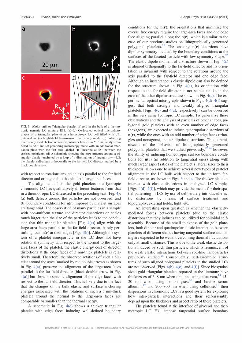
The biosynthesized polygonal platelets impose vertical
boundary conditions for the thermotropic nematic LC direc-
tor.24–30 In a homeotropic cell of E31, the colloidal platelets
align with their large-area faces orthogonally to the vertical
(homeotropic) far-field director, as shown in Fig. 3 for the
case of a triangular particle. A particle induces a disclination
loop encircling it in the plane of the platelet. In some places
around the platelet, the defect loop is pinned to the platelet’s
edge, thus transforming into a surface disclination, and then
becoming a bulk defect line again. The details of director
distortions around such a platelet will need to be explored
further, however, experiments suggest that the observed
defect line is a half-integer disclination of strength s¼ÿ1/2
as shown in the schematic drawing in Fig. 3(d). A similar
disclination loop, also known as a “Saturn ring” defect line,2
can be observed around spherical particles with vertical
boundary conditions.2,30 Because of the homeotropic surface
anchoring, the alignment of the thin gold platelet with
the large-area faces orthogonally to the far-field director and
the observed disclination loops are expected to correspond to
the minimum-elastic-energy alignment and director struc-
ture. Since the normal vector of the platelet plane is parallel
to director field n(r), the induced director distortions ideally
have the DN symmetry of the polygonal platelet with N edge
faces. However, the spontaneous pinning of the defect line to
the edge faces of the platelet may break the DN symmetry.
This spontaneous formation of topological defect lines
around the colloids could lead to qualitatively different elas-
ticity- and defect-mediated modes of colloidal self-assembly
than those seen for platelets with tangential boundary condi-
tions25,26 and spherical particles.1,2,27 From the elastic
energy standpoint, the orientations of the gold triangular pla-
telets with the induced distortions around them are invariant
FIG. 2. (Color online) Colloidal platelets obtained by the use of methanol as a solvent. (a) An AFM image of the surface profile, and (b) the depth profile
across the platelets indicate that the polygonal particles are about 5 nm in thickness. (c) Enlarged image of a colloidal platelet. (d) Optical micrograph showing
predominantly colloidal triangles (with some hexagons and nonagons) obtained after drying the dispersion on a glass cover slide. Schematic illustrations of the
(e) double-twinned growth mechanism of hexagons, (f) triply twinned primary growth mechanism of non-equilateral hexagons, and (g) secondary growth on
triply twinned particles that yields nonagons or non-equilateral hexagons.
033535-3 Evans, Beier, and Smalyukh J. Appl. Phys. 110, 033535 (2011)
Downloaded 11 Mar 2012 to 128.138.65.186. Redistribution subject to AIP license or copyright; see http://jap.aip.org/about/rights_and_permissions
with respect to rotations around an axis parallel to the far field
director and orthogonal to the platelet’s large-area faces.
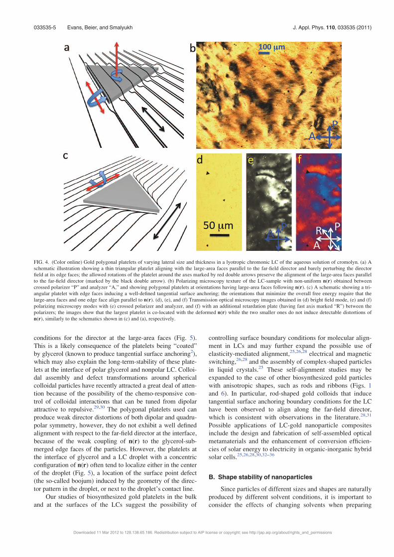
The alignment of similar gold platelets in a lyotropic
chromonic LC has qualitatively different features from that
in a thermotropic LC discussed in the preceding text (Fig. 4):
(a) bulk defects around the particles are not observed, and
(b) boundary conditions for n(r) imposed by platelet surfaces
are tangential. The observation of many particles in a sample
with non-uniform texture and director distortions on scales
much larger than the size of the particles leads to the conclu-
sion that thin triangular platelets [Fig. 4(a)] align with the
large-area faces parallel to the far-field director, barely per-
turbing local n(r) at their edges [Fig. 4(b)]. Although the sys-
tem of a platelet nanoparticle in the LC does not have
rotational symmetry with respect to the normal to the large-
area faces of the platelet, the elastic energy cost of director
distortions at the edge faces of 5 nm-thick platelets is rela-
tively small. Therefore, the observed rotations of such a pla-
telet around the axes [marked by red double arrows as shown
in Fig. 4(a)] preserve the alignment of the large-area faces
parallel to the far-field director [black double arrow in Fig.
4(a)] but show no specific alignment of the edge faces with
respect to the far-field director. This is likely due to the fact
that the changes of the bulk elastic and surface anchoring
energies associated with the rotations of such a 5 nm-thick
platelet around the normal to the large-area faces are
comparable or smaller than the thermal energy.
A schematic in Fig. 4(c) shows a thicker triangular
platelet with edge faces inducing well-defined boundary
conditions for the n(r): the orientations that minimize the
overall free energy require the large-area faces and one edge
face aligning parallel along the n(r), which is similar to the
case of our previous studies on lithographically generated
polygonal platelets.25 The ensuing n(r)-distortions have
dipolar symmetry dictated by the boundary conditions at the
surfaces of the faceted particle with low-symmetry shape.25
The elastic dipole moment of a structure shown in Fig. 4(c)
is aligned orthogonally to the far-field director and its orien-
tation is invariant with respect to the rotations around the
axis parallel to the far-field director and one edge face.
Although an instantaneous elastic dipole can also be defined
for the structure shown in Fig. 4(a), its orientation with
respect to the far-field director is not stable, unlike in the
case of the other dipolar structure shown in Fig. 4(c). The ex-
perimental optical micrographs shown in Figs. 4(d)–4(f) sug-
gest that both strongly and weakly aligned triangular
platelets [Figs. 4(c) and 4(a), respectively] can be observed
in the very same lyotropic LC sample. To generalize these
observations and the analysis of particles of other shapes, po-
lygonal gold platelets with an even number of edge faces
(hexagons) are expected to induce quadrupolar distortions of
n(r), while the ones with an odd number of edge faces (trian-
gles and nonagons), induce dipolar distortions. This is remi-
niscent of the behavior of lithographically generated
polygonal platelets that we studied previously,25,26 however,
the ability of inducing homeotropic surface boundary condi-
tions for n(r) (in addition to tangential ones) along with
much larger aspect ratios of the platelet’s lateral sizes to their
thickness, allows one to achieve several new types of platelet
alignment in the LC bulk with respect to the uniform far-
field director, as shown in Figs. 3 and 4. The thicker platelets
interact with elastic distortions in unaligned LC samples
[Figs. 4(d)–4(f)], which may provide the means for their spa-
tial patterning in LCs by use of deliberately introduced elas-
tic distortions by means of surface treatment and
topography, external fields, light, etc.
An interesting open question is whether the elasticity-
mediated forces between platelets (due to the elastic
distortions that they induce) can be utilized for colloidal self-
assembly. Because of the small thickness of the gold plate-
lets, both dipolar and quadrupolar elastic interaction between
platelets of different shapes having tangential surface anchor-
ing are expected to be weak, overcoming thermal fluctuations
only at small distances. This is due to the weak elastic distor-
tions induced by such thin particles, which is reminiscent of
the weak elastic interactions between rod-like nanoparticles
previously studied.28 Consequently, self-assembled struc-
tures of such aligned polygonal platelets in the studied LCs
are not observed [Figs. 4(b), 4(e), and 4(f)]. Since biosynthe-
sized gold triangular platelets reported in the literature have
thicknesses of 3–8 nm when obtained using aloe vera,18 15–
20 nm when using lemon grass20 and bovine serum
albumin,19 and 200–800 nm when using cellulose,21 their
dispersions in chromonic LCs is a good system for exploring
how inter-particle interactions and their self-assembly
depend upon the thickness and aspect ratio of these platelets.
The platelets found at the interface of glycerol and ther-
motropic LC E31 impose tangential surface boundary
FIG. 3. (Color online) Triangular platelet of gold in the bulk of a thermo-
tropic nematic LC mixture E31. (a)–(c) Co-located optical microphoto-
graphs of a triangular platelet in a homeotropic LC cell filled with E31
obtained in: (a) bright-field transmission microscopy mode, (b) polarizing
microscopy mode between crossed polarizer labeled as “P” and analyzer la-
beled as “A,” and (c) polarizing microscopy mode with an additional retar-
dation plate with the fast axis labeled “R” inserted at 45� between the
crossed polarizers. (d) A schematic showing the n(r)-structure around a tri-
angular platelet encircled by a loop of a disclination of strength s¼ÿ1/2;
the platelet self-aligns orthogonally to the far-field LC director marked by a
black double arrow.
033535-4 Evans, Beier, and Smalyukh J. Appl. Phys. 110, 033535 (2011)
Downloaded 11 Mar 2012 to 128.138.65.186. Redistribution subject to AIP license or copyright; see http://jap.aip.org/about/rights_and_permissions
conditions for the director at the large-area faces (Fig. 5).
This is a likely consequence of the platelets being “coated”
by glycerol (known to produce tangential surface anchoring2),
which may also explain the long-term-stability of these plate-
lets at the interface of polar glycerol and nonpolar LC. Colloi-
dal assembly and defect transformations around spherical
colloidal particles have recently attracted a great deal of atten-
tion because of the possibility of the chemo-responsive con-
trol of colloidal interactions that can be tuned from dipolar
attractive to repulsive.29,30 The polygonal platelets used can
produce weak director distortions of both dipolar and quadru-
polar symmetry, however, they do not exhibit a well defined
alignment with respect to the far-field director at the interface,
because of the weak coupling of n(r) to the glycerol-sub-
merged edge faces of the particles. However, the platelets at
the interface of glycerol and a LC droplet with a concentric
configuration of n(r) often tend to localize either in the center
of the droplet (Fig. 5), a location of the surface point defect
(the so-called boojum) induced by the geometry of the direc-
tor pattern in the droplet, or next to the droplet’s contact line.
Our studies of biosynthesized gold platelets in the bulk
and at the surfaces of the LCs suggest the possibility of
controlling surface boundary conditions for molecular align-
ment in LCs and may further expand the possible use of
elasticity-mediated alignment,25,26,28 electrical and magnetic
switching,26,28 and the assembly of complex-shaped particles
in liquid crystals.25 These self-alignment studies may be
expanded to the case of other biosynthesized gold particles
with anisotropic shapes, such as rods and ribbons (Figs. 1
and 6). In particular, rod-shaped gold colloids that induce
tangential surface anchoring boundary conditions for the LC
have been observed to align along the far-field director,
which is consistent with observations in the literature.28,31
Possible applications of LC-gold nanoparticle composites
include the design and fabrication of self-assembled optical
metamaterials and the enhancement of conversion efficien-
cies of solar energy to electricity in organic-inorganic hybrid
solar cells.25,26,28,30,32–36
B. Shape stability of nanoparticles
Since particles of different sizes and shapes are naturally
produced by different solvent conditions, it is important to
consider the effects of changing solvents when preparing
FIG. 4. (Color online) Gold polygonal platelets of varying lateral size and thickness in a lyotropic chromonic LC of the aqueous solution of cromolyn. (a) A
schematic illustration showing a thin triangular platelet aligning with the large-area faces parallel to the far-field director and barely perturbing the director
field at its edge faces; the allowed rotations of the platelet around the axes marked by red double arrows preserve the alignment of the large-area faces parallel
to the far-field director (marked by the black double arrow). (b) Polarizing microscopy texture of the LC-sample with non-uniform n(r) obtained between
crossed polarizer “P” and analyzer “A,” and showing polygonal platelets at orientations having large-area faces following n(r). (c) A schematic showing a tri-
angular platelet with edge faces inducing a well-defined tangential surface anchoring; the orientations that minimize the overall free energy require that the
large-area faces and one edge face align parallel to n(r). (d), (e), and (f) Transmission optical microscopy images obtained in (d) bright field mode, (e) and (f)
polarizing microscopy modes with (e) crossed polarizer and analyzer, and (f) with an additional retardation plate (having fast axis marked “R”) between the
polarizers; the images show that the largest platelet is co-located with the deformed n(r) while the two smaller ones do not induce detectable distortions of
n(r), similarly to the schematics shown in (c) and (a), respectively.
033535-5 Evans, Beier, and Smalyukh J. Appl. Phys. 110, 033535 (2011)
Downloaded 11 Mar 2012 to 128.138.65.186. Redistribution subject to AIP license or copyright; see http://jap.aip.org/about/rights_and_permissions
LC-nanoparticle composites. This is especially important
since the redispersion of these nanoparticles into LCs often
requires involving intermediate solvents. We observe that,
upon phase transfer, single nanoparticles can change their
shape and maintain their size or retain both shape and size
(Fig. 6). For example, the methanol synthesized microtrian-
gles are stable for several days in water, glycerol [Fig. 6(d)],
and chromonic LCs. The shapes of methanol-synthesized
gold platelets are also short-term stable (for about one day,
typically becoming somewhat rounded after several days and
eventually spherical) in the bulk of the thermotropic and
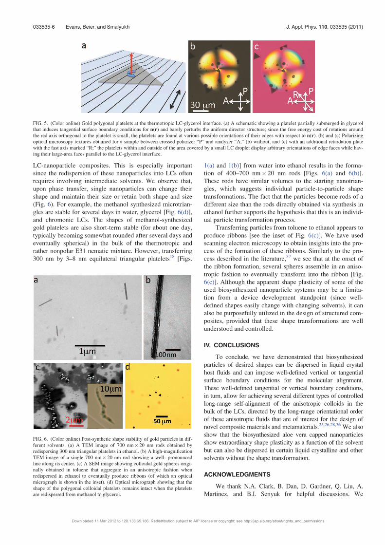
rather nonpolar E31 nematic mixture. However, transferring
300 nm by 3–8 nm equilateral triangular platelets18 [Figs.
1(a) and 1(b)] from water into ethanol results in the forma-
tion of 400–700 nm� 20 nm rods [Figs. 6(a) and 6(b)].
These rods have similar volumes to the starting nanotrian-
gles, which suggests individual particle-to-particle shape
transformations. The fact that the particles become rods of a
different size than the rods directly obtained via synthesis in
ethanol further supports the hypothesis that this is an individ-
ual particle transformation process.
Transferring particles from toluene to ethanol appears to
produce ribbons [see the inset of Fig. 6(c)]. We have used
scanning electron microscopy to obtain insights into the pro-
cess of the formation of these ribbons. Similarly to the pro-
cess described in the literature,37 we see that at the onset of
the ribbon formation, several spheres assemble in an aniso-
tropic fashion to eventually transform into the ribbon [Fig.
6(c)]. Although the apparent shape plasticity of some of the
used biosynthesized nanoparticle systems may be a limita-
tion from a device development standpoint (since well-
defined shapes easily change with changing solvents), it can
also be purposefully utilized in the design of structured com-
posites, provided that these shape transformations are well
understood and controlled.
IV. CONCLUSIONS
To conclude, we have demonstrated that biosynthesized
particles of desired shapes can be dispersed in liquid crystal
host fluids and can impose well-defined vertical or tangential
surface boundary conditions for the molecular alignment.
These well-defined tangential or vertical boundary conditions,
in turn, allow for achieving several different types of controlled
long-range self-alignment of the anisotropic colloids in the
bulk of the LCs, directed by the long-range orientational order
of these anisotropic fluids that are of interest for the design of
novel composite materials and metamaterials.25,26,28,36 We also
show that the biosynthesized aloe vera capped nanoparticles
show extraordinary shape plasticity as a function of the solvent
but can also be dispersed in certain liquid crystalline and other
solvents without the shape transformation.
ACKNOWLEDGMENTS
We thank N.A. Clark, B. Dan, D. Gardner, Q. Liu, A.
Martinez, and B.I. Senyuk for helpful discussions. We
FIG. 5. (Color online) Gold polygonal platelets at the thermotropic LC-glycerol interface. (a) A schematic showing a platelet partially submerged in glycerol
that induces tangential surface boundary conditions for n(r) and barely perturbs the uniform director structure; since the free energy cost of rotations around
the red axis orthogonal to the platelet is small, the platelets are found at various possible orientations of their edges with respect to n(r). (b) and (c) Polarizing
optical microscopy textures obtained for a sample between crossed polarizer “P” and analyzer “A,” (b) without, and (c) with an additional retardation plate
with the fast axis marked “R;” the platelets within and outside of the area covered by a small LC droplet display arbitrary orientations of edge faces while hav-
ing their large-area faces parallel to the LC-glycerol interface.
FIG. 6. (Color online) Post-synthetic shape stability of gold particles in dif-
ferent solvents. (a) A TEM image of 700 nm� 20 nm rods obtained by
redispersing 300 nm triangular platelets in ethanol. (b) A high-magnification
TEM image of a single 700 nm� 20 nm rod showing a well- pronounced
line along its center. (c) A SEM image showing colloidal gold spheres origi-
nally obtained in toluene that aggregate in an anisotropic fashion when
redispersed in ethanol to eventually produce ribbons (of which an optical
micrograph is shown in the inset). (d) Optical micrograph showing that the
shape of the polygonal colloidal platelets remains intact when the platelets
are redispersed from methanol to glycerol.
033535-6 Evans, Beier, and Smalyukh J. Appl. Phys. 110, 033535 (2011)
Downloaded 11 Mar 2012 to 128.138.65.186. Redistribution subject to AIP license or copyright; see http://jap.aip.org/about/rights_and_permissions
acknowledge the support of the International Institute for
Complex Adaptive Matter, CO Renewable and Sustainable
Energy Initiative, the University of Colorado Innovation Seed
Grant Program, and the National Science Foundation Grant
Nos. DMR-0820579, DMR-0844115, and DMR-0847782.
1P. Poulin, H. Stark, T. C. Lubensky, and D. A. Weitz, Science 275, 1770
(1997).2H. Stark, Phys Rep. 351, 387 (2001).3P. Poulin and D. A. Weitz, Phys. Rev E 57, 626 (1998).4C. L. van Oosten, C. W. M. Baastiansen, and D. J. Broer, Nature Mater.
8 677 (2009).5I. I. Smalyukh, A. V. Kachynski, A. N. Kuzmin, and P. N. Prasad, Proc.
Natl. Acad. Sci. U.S.A. 103, 18048 (2006).6Y. Gu and N. L. Abbott, Phys. Rev. Lett. 85, 4719 (2000).7C. D. Santangelo and R. D. Kamien, Phys. Rev. Lett. 91, 045506-1 (2003).8S. J. Woltman, D. G. Jay, and G. P. Crawford, Nature Mater. 6, 929
(2007).9J. Yamamoto and H. Tanaka, Nature Mater. 4, 75 (2005).10I. I. Smalyukh, Y. Lansac, N. Clark, R. Trivedi, Nature Mater. 9, 139
(2010).11N. Engheta.Science 317, 1698 (2007).12V. G. Veselago, Sov. Phys. Usp. 10, 509 (1968).13D. A. Pawlak, S. Turczynski, M. Gajc, K. Kolodziejak, R. Diduszko, K.
Rozniatowski, J. Smalc, and I. Vendik, Adv. Funct. Mater. 20, 1116
(2010).14J. B. Pendrey, Phys. Rev. Lett. 85, 3966 (2000).15M. Brust, M. Walker, D. Bethell, D. Schiffrin, and R. Whyman, J. Chem.
Soc., Chem. Commun. 801 (1994).16C. Murphy, T. Sau, A. Gole, C. Orendorff, J. Gao, L. Gou, S. Hunyadi,
and T. Li, J. Phys. Chem. B 109, 13857 (2005).17M. Grzelezak, J. Juste, P. Mulvaney, andL. Liz-Marzan. Chem. Soc. Rev.
37, 1783 (2008).
18S. Chandran, M. Chaudhary, R. Pasricha, A. Ahmad, and M. Sastry,
Biotechnol. Prog. 22, 577 (2006).19J. Xie, J. Y. Lee, and D. Y. C. Wang. J. Phys. Chem. C 111, 10226
(2007).20S. Shankar, A. Rai, B. Ankamwar, A. Singh, A. Ahmad, and M. Sastry,
Nature Mater. 3, 482 (2004).21Z. Li, A. Friedrich, and A. Taubert, J. Mater. Chem. 18, 1008 (2007).22S. Stoeva, V. Zaikovski, B. Prasad, B. Stoimenov, C. Sorensen, and
K. Klabunde, Langmuir 21, 10280 (2005).23C. Lofton and W. Sigmund, Adv. Funct. Mater. 15, 1197 (2005).24M. Zapotocky, L. Ramos, P. Poulin, T. C. Lubensky, and D. A. Weitz, Sci-
ence 283, 209 (1999).25C. Lapointe, T. Mason, and I. I. Smalyukh, Science 326, 1083 (2009).26C. Lapointe, S. Hopkins, T. G. Mason, and I. I. Smalyukh, Phys. Rev. Lett.
105, 178301 (2010).27T. Yamamoto, Y. Tabe, and H. Yokoyama, Colloids Surf., A 334, 155
(2009).28Q. Liu, Y. Cui, D. Gardner, X. Li, S. He, and I. I. Smalyukh, Nano Lett.
10, 1347 (2010).29G. M. Koenig, I.-H. Lin, and N. L. Abbott, Proc. Natl. Acad. Sci. U.S.A.
107, 3998 (2010).30I. I. Smalyukh, Proc. Natl. Acad. Sci. U.S.A. 107, 3945 (2010).31I. I. Smalyukh, J. Butler, J. D. Shrout, M. R. Parsek, and G. C. L. Wong,
Phys. Rev. E 78, 030701(R) (2008).32T. H. Reilly III, R. C. Tenent, T. M. Barnes, K. L. Rowlen, and J. van de
Lagemaat, ACS Nano 2, 615 (2010).33J. C. Johnson, T. H. Reilly III, A. C. Kanarr, and J. van de Lagemaat,
J. Phys. Chem. C 113, 6871 (2009).34H. A. Atwater and A. Polman, Nature Mater. 9, 205 (2010).35M. J. Romero, A. J. Morfa, T. H. Reilly III, J. van de Lagemaat, and
M. Al-Jassim, Nano Lett. 9, 3904 (2009).36M. R. Jones, R. J. Macfarlane, B. Lee, J. Zhang, K. L. Young, A. J. Senesi,
and C. A. Mirkin, Nature Mater. 9, 913 (2010).37Y. Tan, J. Lee, and D. Wang, J. Phys. Chem. C 112, 5463 (2008).
033535-7 Evans, Beier, and Smalyukh J. Appl. Phys. 110, 033535 (2011)
Downloaded 11 Mar 2012 to 128.138.65.186. Redistribution subject to AIP license or copyright; see http://jap.aip.org/about/rights_and_permissions