Embed Size (px)
DESCRIPTION
Alivesata2 Glan
Citation preview

11111
ALiveSATA2-GLAN
User Manual
Version 1.4Published February 2007
Copyright©2007 ASRock INC. All rights reserved.
22222
Copyright Notice:Copyright Notice:Copyright Notice:Copyright Notice:Copyright Notice:No part of this manual may be reproduced, transcribed, transmitted, or translated inany language, in any form or by any means, except duplication of documentation bythe purchaser for backup purpose, without written consent of ASRock Inc.Products and corporate names appearing in this manual may or may not be regis-tered trademarks or copyrights of their respective companies, and are used only foridentification or explanation and to the owners’ benefit, without intent to infringe.
Disclaimer:Disclaimer:Disclaimer:Disclaimer:Disclaimer:Specifications and information contained in this manual are furnished for informa-tional use only and subject to change without notice, and should not be constructedas a commitment by ASRock. ASRock assumes no responsibility for any errors oromissions that may appear in this manual.With respect to the contents of this manual, ASRock does not provide warranty ofany kind, either expressed or implied, including but not limited to the implied warran-ties or conditions of merchantability or fitness for a particular purpose.In no event shall ASRock, its directors, officers, employees, or agents be liable forany indirect, special, incidental, or consequential damages (including damages forloss of profits, loss of business, loss of data, interruption of business and the like),even if ASRock has been advised of the possibility of such damages arising from anydefect or error in the manual or product.
This device complies with Part 15 of the FCC Rules. Operation is subject to thefollowing two conditions:(1) this device may not cause harmful interference, and(2) this device must accept any interference received, including interference that
may cause undesired operation.
CALIFORNIA, USA ONLYThe Lithium battery adopted on this motherboard contains Perchlorate, a toxicsubstance controlled in Perchlorate Best Management Practices (BMP) regulationspassed by the California Legislature. When you discard the Lithium battery inCalifornia, USA, please follow the related regulations in advance.“Perchlorate Material-special handling may apply, seewww.dtsc.ca.gov/hazardouswaste/perchlorate”
ASRock Website: http://www.asrock.com
33333
ContentsContentsContentsContentsContents1.1.1.1.1. IntroductionIntroductionIntroductionIntroductionIntroduction ............................................................................................................................................................................................................................................................................................................ 5 5 5 5 5
1.1 Package Contents ..................................................................... 51.2 Specifications ........................................................................... 61.3 Minimum Hardware Requirement Table for Windows® VistaTM
Premium 2007 and Basic Logo ................................................. 91.4 Motherboard Layout ................................................................. 101.5 HD 8CH I/O Panel ....................................................................... 11
2.2.2.2.2. InstallationInstallationInstallationInstallationInstallation ...................................................................................................................................................................................................................................................................................................................... 12 12 12 12 12Pre-installation Precautions ............................................................... 122.1 CPU Installation ......................................................................... 132.2 Installation of CPU Fan and Heatsink ....................................... 132.3 Installation of Memory Modules (DIMM) .................................... 142.4 Expansion Slots (PCI and PCIE Slots) .............................................. 162.5 Jumpers Setup .......................................................................... 172.6 Onboard Headers and Connectors .......................................... 182.7 HDMI_SPDIF Header Connection Guide .................................... 222.8 SATAII Hard Disk Setup Guide .................................................. 232.9 Serial ATA (SATA) / Serial ATAII (SATAII) Hard Disks Installation
.................................................................................................. 242.10 Hot Plug and Hot Swap Functions for SATA / SATAII HDDs .... 242.11 Driver Installation Guide ............................................................ 252.12 Installing Windows® 2000 / XP / XP 64-bit / VistaTM /
VistaTM 64-bit With RAID Functions .......................................... 252.12.1 Installing Windows® 2000 / XP / XP 64-bit With RAID
Functions ...................................................................... 252.12.2 Installing Windows® VistaTM / VistaTM 64-bit With RAID
Functions ...................................................................... 272.13 Installing Windows® 2000 / XP / XP 64-bit / VistaTM /
VistaTM 64-bit Without RAID Functions ..................................... 282.13.1 Installing Windows® 2000 / XP / XP 64-bit Without RAID
Functions ...................................................................... 282.13.2 Installing Windows® VistaTM / VistaTM 64-bit Without RAID
Functions ...................................................................... 292.14 Untied Overclocking Technology .............................................. 29
3.3.3.3.3. BIOS SBIOS SBIOS SBIOS SBIOS SETUP UTILITYETUP UTILITYETUP UTILITYETUP UTILITYETUP UTILITY ............................................................................................................................................................................................................................................................... 30 30 30 30 303.1 Introduction ............................................................................... 30
3.1.1 BIOS Menu Bar ............................................................... 303.1.2 Navigation Keys ............................................................. 31
3.2 Main Screen .............................................................................. 31

44444
3.3 Advanced Screen .................................................................... 323.3.1 CPU Configuration .......................................................... 323.3.2 Chipset Configuration ..................................................... 353.3.3 ACPI Configuration ......................................................... 373.3.4 IDE Configuration ............................................................ 383.3.5 PCIPnP Configuration ...................................................... 413.3.6 Floppy Configuration ...................................................... 413.3.7 Super IO Configuration ................................................... 423.3.8 USB Configuration .......................................................... 43
3.4 Hardware Health Event Monitoring Screen ............................. 443.5 Boot Screen .............................................................................. 44
3.5.1 Boot Settings Configuration ........................................... 453.6 Security Screen ........................................................................ 453.7 Exit Screen ............................................................................... 46
4.4.4.4.4. Software SupportSoftware SupportSoftware SupportSoftware SupportSoftware Support ............................................................................................................................................................................................................................................................... 47 47 47 47 474.1 Install Operating System ........................................................... 474.2 Support CD Information ............................................................. 47
4.2.1 Running Support CD ....................................................... 474.2.2 Drivers Menu .................................................................. 474.2.3 Utilities Menu ................................................................... 474.2.4 Contact Information ........................................................ 47
55555
1.1.1.1.1. IntroductionIntroductionIntroductionIntroductionIntroductionThank you for purchasing ASRock ALiveSATA2-GLAN motherboard, a reliablemotherboard produced under ASRock’s consistently stringent quality control. It de-livers excellent performance with robust design conforming to ASRock’s commit-ment to quality and endurance.In this manual, chapter 1 and 2 contain introduction of the motherboard and step-by-step guide to the hardware installation. Chapter 3 and 4 contain the configurationguide to BIOS setup and information of the Support CD.
Because the motherboard specifications and the BIOS software might beupdated, the content of this manual will be subject to change withoutnotice. In case any modifications of this manual occur, the updatedversion will be available on ASRock website without further notice. Youmay find the latest VGA cards and CPU support lists on ASRock websiteas well. ASRock website http://www.asrock.com
1.11.11.11.11.1 Package ContentsPackage ContentsPackage ContentsPackage ContentsPackage Contents1 x ASRock ALiveSATA2-GLAN Motherboard
(ATX Form Factor: 12.0-in x 8.0-in, 30.5 cm x 20.3 cm)1 x ASRock ALiveSATA2-GLAN Quick Installation Guide1 x ASRock ALiveSATA2-GLAN Support CD1 x Ultra ATA 66/100/133 IDE Ribbon Cable (80-conductor)1 x 3.5-in Floppy Drive Ribbon Cable1 x Serial ATA (SATA) Data Cable (Optional)1 x Serial ATA (SATA) HDD Power Cable (Optional)1 x HDMI_SPDIF Cable (Optional)1 x HD 8CH I/O Shield
66666
1.21.21.21.21.2 SpecificationsSpecificationsSpecificationsSpecificationsSpecifications
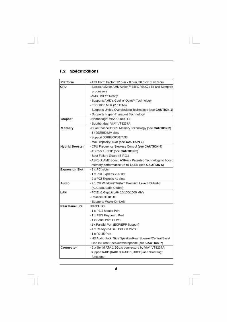
Platform - ATX Form Factor: 12.0-in x 8.0-in, 30.5 cm x 20.3 cm CPU - Socket AM2 for AMD AthlonTM 64FX / 64X2 / 64 and Sempron
processors- AMD LIVE!TM Ready- Supports AMD’s Cool ‘n’ QuietTM Technology- FSB 1000 MHz (2.0 GT/s)- Supports Untied Overclocking Technology (see CAUTION 1)- Supports Hyper-Transport Technology
Chipset - Northbridge: VIA® K8T890 CF- Southbridge: VIA® VT8237A
Memory - Dual Channel DDRII Memory Technology (see CAUTION 2)- 4 x DDRII DIMM slots- Support DDRII800/667/533- Max. capacity: 8GB (see CAUTION 3)
Hybrid Booster - CPU Frequency Stepless Control (see CAUTION 4)- ASRock U-COP (see CAUTION 5)- Boot Failure Guard (B.F.G.)- ASRock AM2 Boost: ASRock Patented Technology to boost memory performance up to 12.5% (see CAUTION 6)
Expansion Slot - 3 x PCI slots- 1 x PCI Express x16 slot- 2 x PCI Express x1 slots
Audio - 7.1 CH Windows® VistaTM Premium Level HD Audio (ALC888 Audio Codec)
LAN - PCIE x1 Gigabit LAN 10/100/1000 Mb/s- Realtek RTL8111B- Supports Wake-On-LAN
Rear Panel I/O HD 8CH I/O- 1 x PS/2 Mouse Port- 1 x PS/2 Keyboard Port- 1 x Serial Port: COM1- 1 x Parallel Port (ECP/EPP Support)- 4 x Ready-to-Use USB 2.0 Ports- 1 x RJ-45 Port- HD Audio Jack: Side Speaker/Rear Speaker/Central/Bass/ Line in/Front Speaker/Microphone (see CAUTION 7)
Connector - 2 x Serial ATA 1.5Gb/s connectors by VIA® VT8237A, support RAID (RAID 0, RAID 1, JBOD) and “Hot Plug” functions

77777
- 2 x SATAII 3.0Gb/s connectors by JMicron® JMB 363 (PCIE x1 interface), support RAID (RAID 0, RAID 1, JBOD), NCQ, AHCI and “Hot Plug” functions (see CAUTION 8)- 2 x ATA133 IDE connectors (support 4 x IDE devices)- 1 x Floppy connector- 1 x IR header- 1 x Game header- 1 x HDMI_SPDIF header- CPU/Chassis FAN connector- 20 pin ATX power connector- 4 pin 12V power connector- CD in header- Front panel audio connector- 2 x USB 2.0 headers (support 4 USB 2.0 ports) (see CAUTION 9)
BIOS Feature - 4Mb AMI BIOS- AMI Legal BIOS- Supports “Plug and Play”- ACPI 1.1 Compliance Wake Up Events- Supports jumperfree- SMBIOS 2.3.1 Support
Support CD - Drivers, Utilities, AntiVirus Software (Trial Version) Hardware - CPU Internal Temperature Sensing Monitor - CPU Ambient Temperature Sensing
- Chassis Temperature Sensing- CPU Fan Tachometer- Chassis Fan Tachometer- CPU Quiet Fan- Voltage Monitoring: +12V, +5V, +3.3V, Vcore
OS - Microsoft® Windows® 2000/XP/XP 64-bit/VistaTM / VistaTM
64-bit compliant (see CAUTION 10) Certifications - FCC, CE, Microsoft® WHQL Certificated
WARNINGPlease realize that there is a certain risk involved with overclocking, including adjustingthe setting in the BIOS, applying Untied Overclocking Technology, or using the third-party overclocking tools. Overclocking may affect your system stability, or evencause damage to the components and devices of your system. It should be done atyour own risk and expense. We are not responsible for possible damage caused byoverclocking.
88888
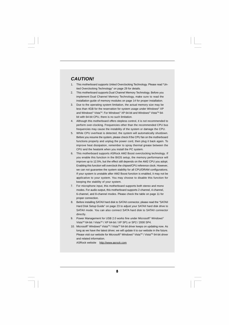
CAUTION!1. This motherboard supports Untied Overclocking Technology. Please read “Un-
tied Overclocking Technology” on page 29 for details.2. This motherboard supports Dual Channel Memory Technology. Before you
implement Dual Channel Memory Technology, make sure to read theinstallation guide of memory modules on page 14 for proper installation.
3. Due to the operating system limitation, the actual memory size may beless than 4GB for the reservation for system usage under Windows® XPand Windows® VistaTM. For Windows® XP 64-bit and Windows® VistaTM 64-bit with 64-bit CPU, there is no such limitation.
4. Although this motherboard offers stepless control, it is not recommended toperform over-clocking. Frequencies other than the recommended CPU busfrequencies may cause the instability of the system or damage the CPU.
5. While CPU overheat is detected, the system will automatically shutdown.Before you resume the system, please check if the CPU fan on the motherboardfunctions properly and unplug the power cord, then plug it back again. Toimprove heat dissipation, remember to spray thermal grease between theCPU and the heatsink when you install the PC system.
6. This motherboard supports ASRock AM2 Boost overclocking technology. Ifyou enable this function in the BIOS setup, the memory performance willimprove up to 12.5%, but the effect still depends on the AM2 CPU you adopt.Enabling this function will overclock the chipset/CPU reference clock. However,we can not guarantee the system stability for all CPU/DRAM configurations.If your system is unstable after AM2 Boost function is enabled, it may not beapplicative to your system. You may choose to disable this function forkeeping the stability of your system.
7. For microphone input, this motherboard supports both stereo and monomodes. For audio output, this motherboard supports 2-channel, 4-channel,6-channel, and 8-channel modes. Please check the table on page 11 forproper connection.
8. Before installing SATAII hard disk to SATAII connector, please read the “SATAIIHard Disk Setup Guide” on page 23 to adjust your SATAII hard disk drive toSATAII mode. You can also connect SATA hard disk to SATAII connectordirectly.
9. Power Management for USB 2.0 works fine under Microsoft® Windows®
VistaTM 64-bit / VistaTM / XP 64-bit / XP SP1 or SP2 / 2000 SP4.10. Microsoft® Windows® VistaTM / VistaTM 64-bit driver keeps on updating now. As
long as we have the latest driver, we will update it to our website in the future.Please visit our website for Microsoft® Windows® VistaTM / VistaTM 64-bit driverand related information.ASRock website http://www.asrock.com

99999
1.31.31.31.31.3 Minimum Hardware RMinimum Hardware RMinimum Hardware RMinimum Hardware RMinimum Hardware Requirement Tequirement Tequirement Tequirement Tequirement Table for Wable for Wable for Wable for Wable for Windowsindowsindowsindowsindows®®®®®
VistaVistaVistaVistaVistaTMTMTMTMTM Premium 2007 and Basic Logo Premium 2007 and Basic Logo Premium 2007 and Basic Logo Premium 2007 and Basic Logo Premium 2007 and Basic LogoFor system integrators and users who purchase this motherboard andplan to submit Windows® VistaTM Premium 2007 and Basic logo, pleasefollow below table for minimum hardware requirements.
CPU Sempron 2800+Memory 1GB system memoryVGA DX9.0 with WDDM Driver
with 128bit VGA memory (Premium)with 64bit VGA memory (Basic)
* After June 1, 2007, all Windows® VistaTM systems are required to meet above minimum hardware requirements in order to qualify for Windows® VistaTM Premium 2007 logo.

1 01 01 01 01 0
1.4 Motherboard Layout1.4 Motherboard Layout1.4 Motherboard Layout1.4 Motherboard Layout1.4 Motherboard Layout
Su
pe
rI/
O
PCIEXPRESS
USB2.0
CMOSBATTERY
AT
XP
WR
1
SOC
KETAM
2
AL
ive
SA
TA
2-G
LA
N
CD1
VIAK8T890 CF
Chipset
VIAVT8237AChipset
ATX12V1
PS2_USB_PWR1
1
USB 2.0T: USB2B: USB3
PA
RA
LL
EL
PO
RT
CO
M1
PS2
Mouse
PS
2K
ey
bo
ard
To
p:
RE
AR
SP
K
Ce
nte
r:S
IDE
SP
K
Bo
ttom
:C
TR
BA
SS
To
p:
LIN
EIN
Ce
nte
r:F
RO
NT
Bo
ttom
:M
ICIN
USB 2.0T: USB0B: USB1
Top:RJ-45
IDE2
FS
B8
00
DD
RII
_1
(64
/72
bit
,2
40
-pin
mo
du
le)
DD
RII
_2
(64
/72
bit
,2
40
-pin
mo
du
le)
FS
B8
00
DD
RII
_3
(64
/72
bit
,2
40
-pin
mo
du
le)
DD
RII
_4
(64
/72
bit
,2
40
-pin
mo
du
le)
PCIE1
PCI1
PCI2
4MbBIOS
LANPHY
AUDIOCODEC
SATA1
SATA2
1
CLRCMOS1
DD
RII
80
0D
ua
lC
ore
CP
U
FS
B1
GH
zD
ua
lC
ha
nn
el
ATA133
SATA
7.1
CH
HD
RAID
CPU_FAN1
HDLED RESET
PLED PWRBTN
1
PANEL 1CHA_FAN1
SPEAKER1
1
USB6_7
1
USB4_5
1
IR1
FLOPPY1GAME1
1
HD_AUDIO1
1
RoHS
30
.5c
m(1
2.0
-in
)
20.3cm (8.0-in)
6 71 2 43 5
8
91011
12
13
14151617181920212223
24
25
2627
28293031
IDE1
PCIE2
PCIE3
PCI3
1
1
HDMI_SPDIF1
32
JMicronJMB363
SATAII_1 SATAII_2
Gig
ab
itL
AN
SATAII
33
34
1 PS2_USB_PWR1 Jumper 17 Primary Serial ATA Connector (SATA1, Black) 2 ATX 12V Power Connector (ATX12V1) 18 Chassis Speaker Header (SPEAKER 1) 3 CPU Fan Connector (CPU_FAN1) 19 Chassis Fan Connector (CHA_FAN1) 4 CPU Heatsink Retention Module 20 Flash Memory 5 AM2 940-Pin CPU Socket 21 Serial ATAII Connector (SATAII_2, Red) 6 2 x 240-pin DDRII DIMM Slots 22 Floppy Connector (FLOPPY1)
(Dual Channel A: DDRII_1, DDRII_2; Yellow) 23 HDMI_SPDIF Header (HDMI_SPDIF1) 7 2 x 240-pin DDRII DIMM Slots 24 Game Port Header (GAME1)
(Dual Channel B: DDRII_3, DDRII_4; Orange) 25 Front Panel Audio Header (HD_AUDIO1) 8 North Bridge Controller 26 PCI Slots (PCI1- 3) 9 Clear CMOS Jumper (CLRCMOS1) 27 Serial ATAII Connector (SATAII_1, Red)10 USB 2.0 Header (USB6_7, Blue) 28 PCI Express x1 Slot (PCIE3)11 USB 2.0 Header (USB4_5, Blue) 29 JMicron JMB363 Chipset (PCIE x1 interface)12 South Bridge Controller 30 Infrared Module Header (IR1)13 Primary IDE Connector (IDE1, Blue) 31 PCI Express x1 Slot (PCIE2)14 Secondary IDE Connector (IDE2, Black) 32 PCI Express x16 Slot (PCIE1)15 Secondary Serial ATA Connector (SATA2, Black) 33 Internal Audio Connector: CD1 (Black)16 System Panel Header (PANEL1) 34 ATX Power Connector (ATXPWR1)
1 11 11 11 11 1
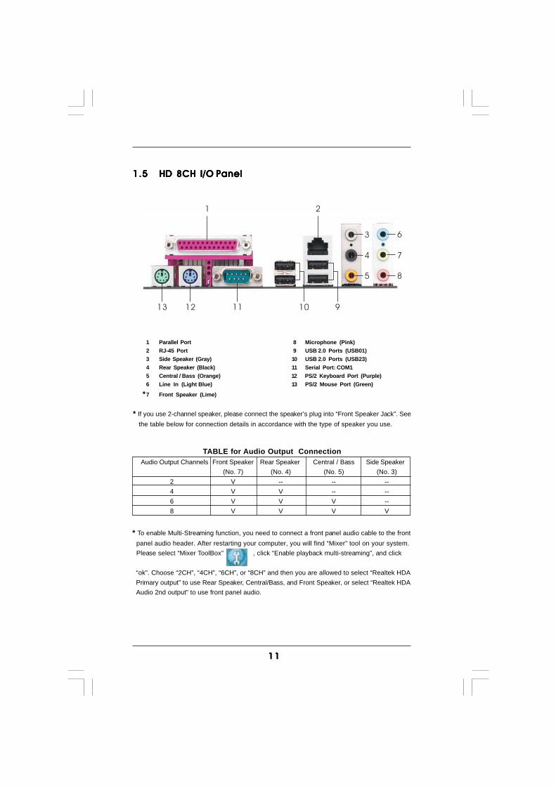
1.51.51.51.51.5 HD 8CH I/OHD 8CH I/OHD 8CH I/OHD 8CH I/OHD 8CH I/O PanelPanelPanelPanelPanel
1 Parallel Port 8 Microphone (Pink)2 RJ-45 Port 9 USB 2.0 Ports (USB01)3 Side Speaker (Gray) 10 USB 2.0 Ports (USB23)4 Rear Speaker (Black) 11 Serial Port: COM15 Central / Bass (Orange) 12 PS/2 Keyboard Port (Purple)6 Line In (Light Blue) 13 PS/2 Mouse Port (Green)
*7 Front Speaker (Lime)
* If you use 2-channel speaker, please connect the speaker’s plug into “Front Speaker Jack”. See the table below for connection details in accordance with the type of speaker you use.
TABLE for Audio Output ConnectionAudio Output Channels Front Speaker Rear Speaker Central / Bass Side Speaker
(No. 7) (No. 4) (No. 5) (No. 3)2 V -- -- --4 V V -- --6 V V V --8 V V V V
1 2
3
4
5
6
7
8
910111213
* To enable Multi-Streaming function, you need to connect a front panel audio cable to the front panel audio header. After restarting your computer, you will find “Mixer” tool on your system. Please select “Mixer ToolBox” , click “Enable playback multi-streaming”, and click
“ok”. Choose “2CH”, “4CH”, “6CH”, or “8CH” and then you are allowed to select “Realtek HDA Primary output” to use Rear Speaker, Central/Bass, and Front Speaker, or select “Realtek HDA Audio 2nd output” to use front panel audio.
1 21 21 21 21 2
2.2.2.2.2. InstallationInstallationInstallationInstallationInstallationALiveSATA2-GLAN is an ATX form factor (12.0-in x 8.0-in, 30.5 cm x 20.3 cm)motherboard. Before you install the motherboard, study the configuration of yourchassis to ensure that the motherboard fits into it.
Pre-installation PrecautionsPre-installation PrecautionsPre-installation PrecautionsPre-installation PrecautionsPre-installation PrecautionsTake note of the following precautions before you install motherboardcomponents or change any motherboard settings.
Before you install or remove any component, ensure that thepower is switched off or the power cord is detached from thepower supply. Failure to do so may cause severe damage to themotherboard, peripherals, and/or components.
1. Unplug the power cord from the wall socket before touching anycomponent.
2. To avoid damaging the motherboard components due to staticelectricity, NEVER place your motherboard directly on the carpet orthe like. Also remember to use a grounded wrist strap or touch asafety grounded object before you handle components.
3. Hold components by the edges and do not touch the ICs.4. Whenever you uninstall any component, place it on a grounded anti-
static pad or in the bag that comes with the component.5. When placing screws into the screw holes to secure the motherboard
to the chassis, please do not over-tighten the screws! Doing so maydamage the motherboard.
1 31 31 31 31 3
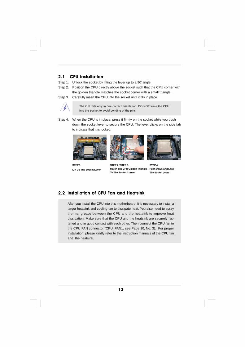
2.12.12.12.12.1 CPU InstallationCPU InstallationCPU InstallationCPU InstallationCPU InstallationStep 1. Unlock the socket by lifting the lever up to a 90o angle.Step 2. Position the CPU directly above the socket such that the CPU corner with
the golden triangle matches the socket corner with a small triangle.Step 3. Carefully insert the CPU into the socket until it fits in place.
The CPU fits only in one correct orientation. DO NOT force the CPUinto the socket to avoid bending of the pins.
Step 4. When the CPU is in place, press it firmly on the socket while you pushdown the socket lever to secure the CPU. The lever clicks on the side tabto indicate that it is locked.
2.22.22.22.22.2 Installation of CPU Fan and HeatsinkInstallation of CPU Fan and HeatsinkInstallation of CPU Fan and HeatsinkInstallation of CPU Fan and HeatsinkInstallation of CPU Fan and Heatsink
After you install the CPU into this motherboard, it is necessary to install alarger heatsink and cooling fan to dissipate heat. You also need to spraythermal grease between the CPU and the heatsink to improve heatdissipation. Make sure that the CPU and the heatsink are securely fas-tened and in good contact with each other. Then connect the CPU fan tothe CPU FAN connector (CPU_FAN1, see Page 10, No. 3). For properinstallation, please kindly refer to the instruction manuals of the CPU fanand the heatsink.
STEP 1:
Lift Up The Socket Lever
STEP 2 / STEP 3:Match The CPU Golden TriangleTo The Socket Corner
STEP 4:Push Down And LockThe Socket Lever
Lever 90° UpCPU Golden Triangle
Socket Corner
1 41 41 41 41 4
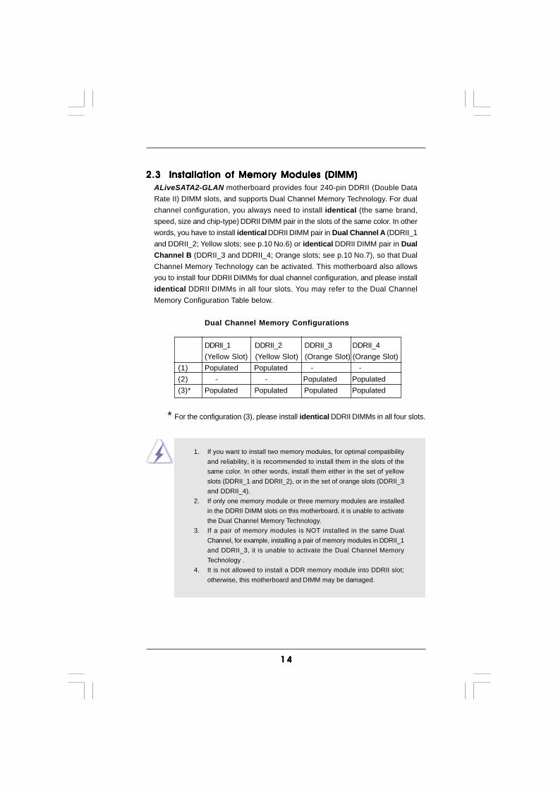
2.3 Installation of Memory Modules (DIMM)2.3 Installation of Memory Modules (DIMM)2.3 Installation of Memory Modules (DIMM)2.3 Installation of Memory Modules (DIMM)2.3 Installation of Memory Modules (DIMM)ALiveSATA2-GLAN motherboard provides four 240-pin DDRII (Double DataRate II) DIMM slots, and supports Dual Channel Memory Technology. For dualchannel configuration, you always need to install identical (the same brand,speed, size and chip-type) DDRII DIMM pair in the slots of the same color. In otherwords, you have to install identical DDRII DIMM pair in Dual Channel A (DDRII_1and DDRII_2; Yellow slots; see p.10 No.6) or identical DDRII DIMM pair in DualChannel B (DDRII_3 and DDRII_4; Orange slots; see p.10 No.7), so that DualChannel Memory Technology can be activated. This motherboard also allowsyou to install four DDRII DIMMs for dual channel configuration, and please installidentical DDRII DIMMs in all four slots. You may refer to the Dual ChannelMemory Configuration Table below.
Dual Channel Memory Configurations
DDRII_1 DDRII_2 DDRII_3 DDRII_4(Yellow Slot) (Yellow Slot) (Orange Slot) (Orange Slot)
(1) Populated Populated - -(2) - - Populated Populated(3)* Populated Populated Populated Populated
* For the configuration (3), please install identical DDRII DIMMs in all four slots.
1. If you want to install two memory modules, for optimal compatibilityand reliability, it is recommended to install them in the slots of thesame color. In other words, install them either in the set of yellowslots (DDRII_1 and DDRII_2), or in the set of orange slots (DDRII_3and DDRII_4).
2. If only one memory module or three memory modules are installedin the DDRII DIMM slots on this motherboard, it is unable to activatethe Dual Channel Memory Technology.
3. If a pair of memory modules is NOT installed in the same DualChannel, for example, installing a pair of memory modules in DDRII_1and DDRII_3, it is unable to activate the Dual Channel MemoryTechnology .
4. It is not allowed to install a DDR memory module into DDRII slot;otherwise, this motherboard and DIMM may be damaged.
1 51 51 51 51 5
notch
break
notch
break
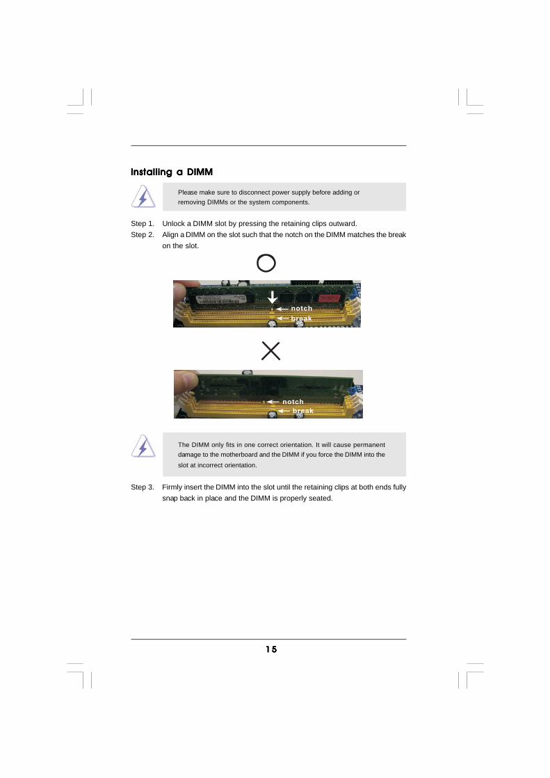
Installing a DIMMInstalling a DIMMInstalling a DIMMInstalling a DIMMInstalling a DIMM
Please make sure to disconnect power supply before adding orremoving DIMMs or the system components.
Step 1. Unlock a DIMM slot by pressing the retaining clips outward.Step 2. Align a DIMM on the slot such that the notch on the DIMM matches the break
on the slot.
The DIMM only fits in one correct orientation. It will cause permanentdamage to the motherboard and the DIMM if you force the DIMM into theslot at incorrect orientation.
Step 3. Firmly insert the DIMM into the slot until the retaining clips at both ends fullysnap back in place and the DIMM is properly seated.
1 61 61 61 61 6
2.42.42.42.42.4 Expansion Slots (PCI Slots and PCIE Slots)Expansion Slots (PCI Slots and PCIE Slots)Expansion Slots (PCI Slots and PCIE Slots)Expansion Slots (PCI Slots and PCIE Slots)Expansion Slots (PCI Slots and PCIE Slots)There are 3 PCI slots and 3 PCI Express slots on ALiveSATA2-GLAN motherboard.
PCI Slots: PCI slots are used to install expansion cards that have the 32-bit PCIinterface.
PCIE Slots: PCIE1 (PCIE x16 slot) is used for PCI Express cards with x16 lane width graphics cards. PCIE2 / PCIE3 (PCIE x1 slot) is used for PCI Express cards with x1 lane width cards, such as Gigabit LAN card, SATA2 card, etc.
Installing an expansion cardInstalling an expansion cardInstalling an expansion cardInstalling an expansion cardInstalling an expansion cardStep 1. Before installing the expansion card, please make sure that the power
supply is switched off or the power cord is unplugged. Please read thedocumentation of the expansion card and make necessary hardwaresettings for the card before you start the installation.
Step 2. Remove the system unit cover (if your motherboard is already installed ina chassis).
Step 3. Remove the bracket facing the slot that you intend to use. Keep thescrews for later use.
Step 4. Align the card connector with the slot and press firmly until the card iscompletely seated on the slot.
Step 5. Fasten the card to the chassis with screws.Step 6. Replace the system cover.
1 71 71 71 71 7
+5V
1_2
+5VSB
2_3
Short Open
2-pin jumper
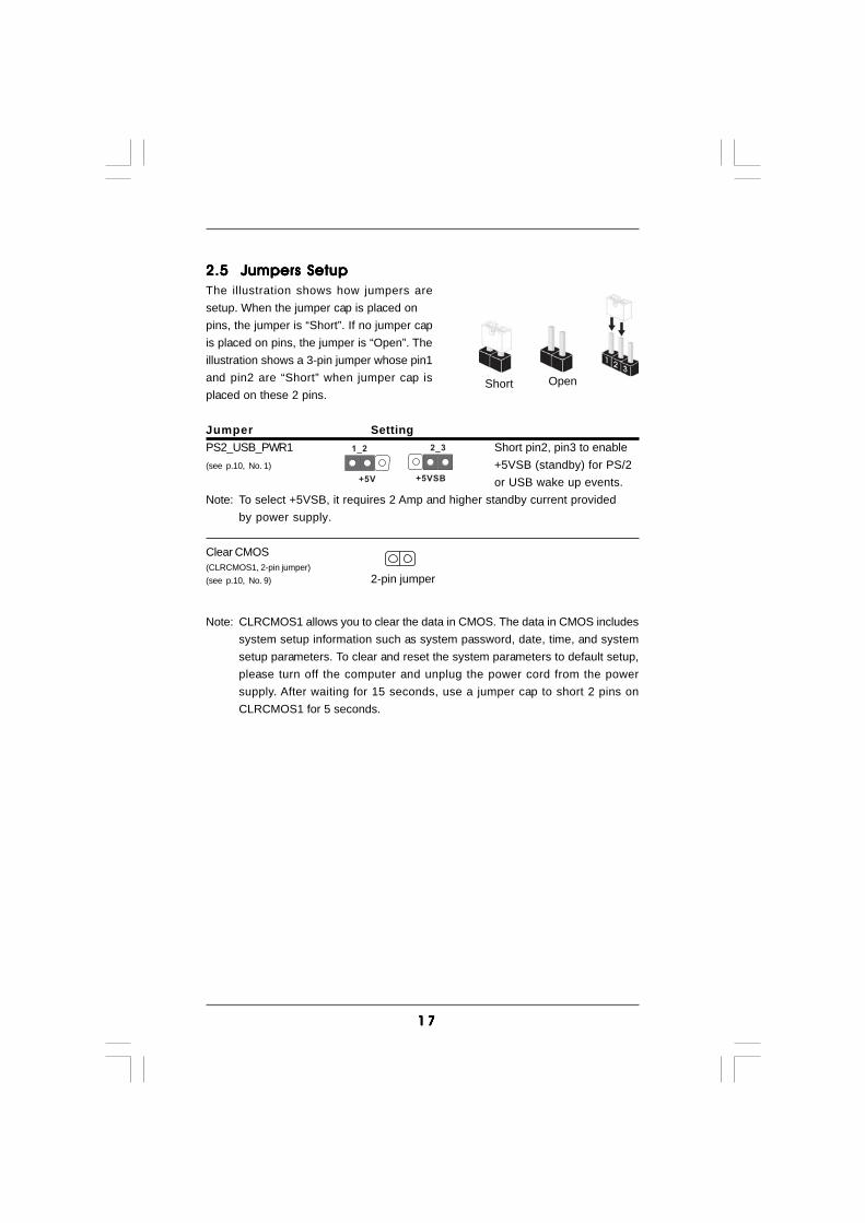
2.5 Jumpers Setup2.5 Jumpers Setup2.5 Jumpers Setup2.5 Jumpers Setup2.5 Jumpers SetupThe illustration shows how jumpers aresetup. When the jumper cap is placed onpins, the jumper is “Short”. If no jumper capis placed on pins, the jumper is “Open”. Theillustration shows a 3-pin jumper whose pin1and pin2 are “Short” when jumper cap isplaced on these 2 pins.
Jumper SettingPS2_USB_PWR1 Short pin2, pin3 to enable(see p.10, No. 1) +5VSB (standby) for PS/2
or USB wake up events.Note: To select +5VSB, it requires 2 Amp and higher standby current provided
by power supply.
Clear CMOS(CLRCMOS1, 2-pin jumper)(see p.10, No. 9)
Note: CLRCMOS1 allows you to clear the data in CMOS. The data in CMOS includessystem setup information such as system password, date, time, and systemsetup parameters. To clear and reset the system parameters to default setup,please turn off the computer and unplug the power cord from the powersupply. After waiting for 15 seconds, use a jumper cap to short 2 pins onCLRCMOS1 for 5 seconds.
1 81 81 81 81 8
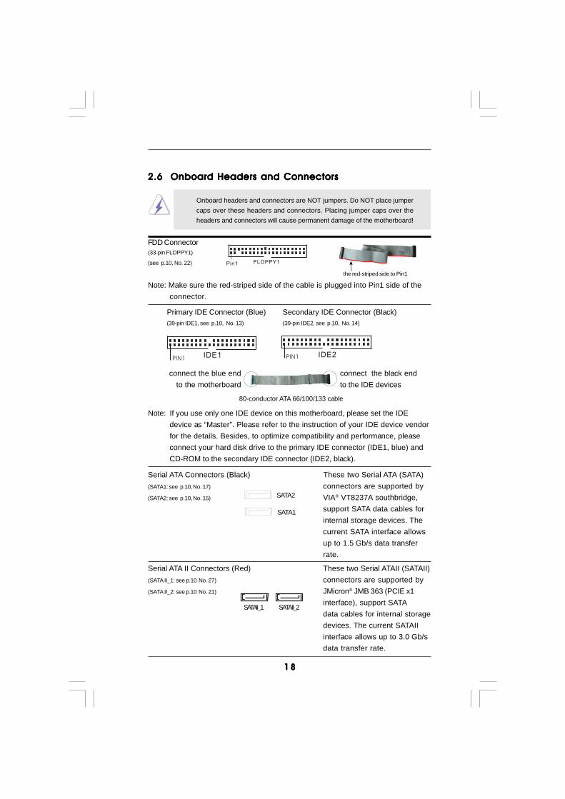
2.6 Onboard Headers and Connectors2.6 Onboard Headers and Connectors2.6 Onboard Headers and Connectors2.6 Onboard Headers and Connectors2.6 Onboard Headers and Connectors
Onboard headers and connectors are NOT jumpers. Do NOT place jumpercaps over these headers and connectors. Placing jumper caps over theheaders and connectors will cause permanent damage of the motherboard!
FDD Connector(33-pin FLOPPY1)
(see p.10, No. 22)
Note: Make sure the red-striped side of the cable is plugged into Pin1 side of theconnector.
SATA1
SATA2
FLOPPY1Pin1
the red-striped side to Pin1
IDE1PIN1IDE2PIN1
connect the black endto the IDE devices
connect the blue endto the motherboard
80-conductor ATA 66/100/133 cable
SATAII_1 SATAII_2
Primary IDE Connector (Blue) Secondary IDE Connector (Black)(39-pin IDE1, see p.10, No. 13) (39-pin IDE2, see p.10, No. 14)
Note: If you use only one IDE device on this motherboard, please set the IDEdevice as “Master”. Please refer to the instruction of your IDE device vendorfor the details. Besides, to optimize compatibility and performance, pleaseconnect your hard disk drive to the primary IDE connector (IDE1, blue) andCD-ROM to the secondary IDE connector (IDE2, black).
Serial ATA Connectors (Black) These two Serial ATA (SATA)(SATA1: see p.10, No. 17) connectors are supported by(SATA2: see p.10, No. 15) VIA® VT8237A southbridge,
support SATA data cables forinternal storage devices. Thecurrent SATA interface allowsup to 1.5 Gb/s data transferrate.
Serial ATA II Connectors (Red) These two Serial ATAII (SATAII)(SATA II_1: see p.10 No. 27) connectors are supported by(SATA II_2: see p.10 No. 21) JMicron® JMB 363 (PCIE x1
interface), support SATAdata cables for internal storagedevices. The current SATAIIinterface allows up to 3.0 Gb/sdata transfer rate.

1 91 91 91 91 9
Serial ATA (SATA) Either end of the SATA data cableData Cable can be connected to the SATA /(Optional) SATAII hard disk or the SATA /
SATAII connector on themotherboard.
Serial ATA (SATA) Please connect the black end ofPower Cable SATA power cable to the power(Optional) connector on the drive. Then
connect the white end of SATApower cable to the powerconnector of the power supply.
USB 2.0 Headers Besides four default USB 2.0(9-pin USB6_7) ports on the I/O panel, there are(see p.10 No. 10) two USB 2.0 headers on this
motherboard. Each USB 2.0header can support two USB2.0 ports.
(9-pin USB4_5)(see p.10 No. 11)
Infrared Module Header This header supports an optional(5-pin IR1) wireless transmitting and(see p.10, No. 30) receiving infrared module.
Internal Audio Connector This connector allows you(4-pin CD1) to receive stereo audio input(CD1: see p.10, No. 33) from sound sources such as
a CD-ROM, DVD-ROM, TVtuner card, or MPEG card.
connect to the SATA HDDpower connector
connect to thepower supply
USB_PWR
USB_PWR
P+7P-7
P+6P-6
GND
GND
DUMMY
1
1
IRTX
IRRXGND
+5VSBDUMMY
CD-L
GNDGND
CD-R
CD1
USB_PWR
USB_PWR
P+5P-5
P+4P-4
GND
GNDDUMMY
1
It is recommended to plug SATAII HDD to SATAII connector (SATAII_1 orSATAII_2) and connect SATA HDD to SATA connector (SATA1 or SATA2).
2 02 02 02 02 0
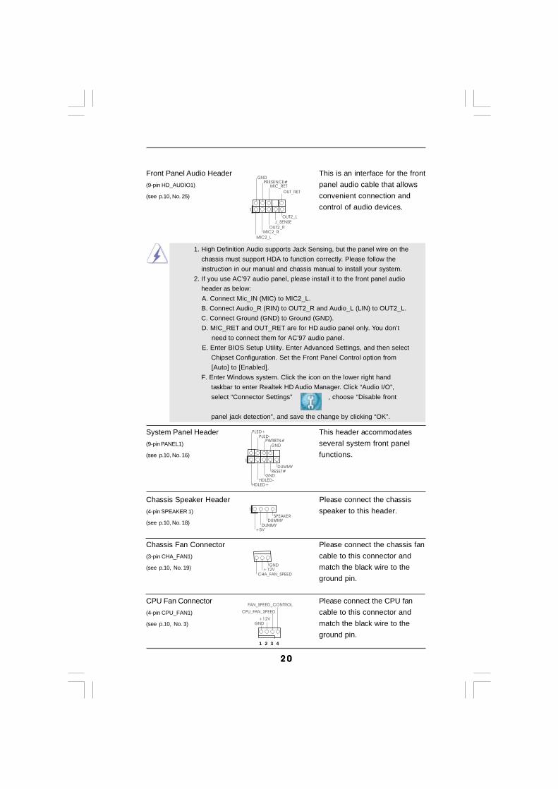
Front Panel Audio Header This is an interface for the front(9-pin HD_AUDIO1) panel audio cable that allows(see p.10, No. 25) convenient connection and
control of audio devices.
System Panel Header This header accommodates(9-pin PANEL1) several system front panel(see p.10, No. 16) functions.
Chassis Speaker Header Please connect the chassis(4-pin SPEAKER 1) speaker to this header.(see p.10, No. 18)
Chassis Fan Connector Please connect the chassis fan(3-pin CHA_FAN1) cable to this connector and(see p.10, No. 19) match the black wire to the
ground pin.
CPU Fan Connector Please connect the CPU fan(4-pin CPU_FAN1) cable to this connector and(see p.10, No. 3) match the black wire to the
ground pin.
GND+12V
CHA_FAN_SPEED
+5V
DUMMYDUMMY
SPEAKER
1
GND
PWRBTN#PLED-
PLED+
DUMMYRESET#
GND
HDLED+HDLED-
1
GND+12V
CPU_FAN_SPEED
FAN_SPEED_CONTROL
J_SENSE
OUT2_L
1
MIC_RETPRESENCE#
GND
OUT2_RMIC2_R
MIC2_L
OUT_RET
1. High Definition Audio supports Jack Sensing, but the panel wire on the chassis must support HDA to function correctly. Please follow the instruction in our manual and chassis manual to install your system.
2. If you use AC’97 audio panel, please install it to the front panel audio header as below: A. Connect Mic_IN (MIC) to MIC2_L. B. Connect Audio_R (RIN) to OUT2_R and Audio_L (LIN) to OUT2_L.
C. Connect Ground (GND) to Ground (GND). D. MIC_RET and OUT_RET are for HD audio panel only. You don’t need to connect them for AC’97 audio panel. E. Enter BIOS Setup Utility. Enter Advanced Settings, and then select
Chipset Configuration. Set the Front Panel Control option from [Auto] to [Enabled]. F. Enter Windows system. Click the icon on the lower right hand taskbar to enter Realtek HD Audio Manager. Click “Audio I/O”, select “Connector Settings” , choose “Disable front
panel jack detection”, and save the change by clicking “OK”.
1 2 3 4
2 12 12 12 12 1
MIDI_OUT
JAB2
JBYJBB2
MIDI_IN
+5V
JAYGND
GND
1
JAXJAB1
+5V
JBXJBB1
+5V
1
GND
+5VSPDIFOUT
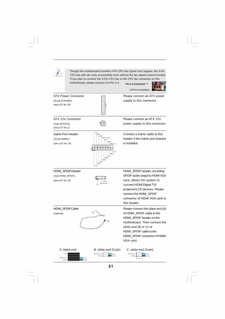
ATX 12V Connector Please connect an ATX 12V(4-pin ATX12V1) power supply to this connector.(see p.10 No. 2)
ATX Power Connector Please connect an ATX power(20-pin ATXPWR1) supply to this connector.(see p.10 No. 34)
HDMI_SPDIF Header HDMI_SPDIF header, providing(3-pin HDMI_SPDIF1) SPDIF audio output to HDMI VGA(see p.10 No. 23) card, allows the system to
connect HDMI Digital TV/projector/LCD devices. Pleaseconnect the HDMI_SPDIFconnector of HDMI VGA card tothis header.
Game Port Header Connect a Game cable to this(15-pin GAME1) header if the Game port bracket(see p.10 No. 24) is installed.
HDMI_SPDIF Cable Please connect the black end (A)(Optional) of HDMI_SPDIF cable to the
HDMI_SPDIF header on themotherboard. Then connect thewhite end (B or C) ofHDMI_SPDIF cable to theHDMI_SPDIF connector of HDMIVGA card.
A. black end B. white end (2-pin) C. white end (3-pin)
CB
GND
+5V
SPDIFOUT blue
black
blue
blackGND
SPDIFOUT blue
blackGND
SPDIFOUT
A
Though this motherboard provides 4-Pin CPU fan (Quiet Fan) support, the 3-Pin CPU fan still can work successfully even without the fan speed control function. If you plan to connect the 3-Pin CPU fan to the CPU fan connector on this motherboard, please connect it to Pin 1-3.
3-Pin Fan Installation
Pin 1-3 Connected
2 22 22 22 22 2
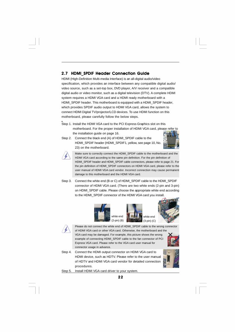
2.7 HDMI_SPDIF Header Connection Guide2.7 HDMI_SPDIF Header Connection Guide2.7 HDMI_SPDIF Header Connection Guide2.7 HDMI_SPDIF Header Connection Guide2.7 HDMI_SPDIF Header Connection GuideHDMI (High-Definition Multi-media Interface) is an all-digital audio/videospecification, which provides an interface between any compatible digital audio/video source, such as a set-top box, DVD player, A/V receiver and a compatibledigital audio or video monitor, such as a digital television (DTV). A complete HDMIsystem requires a HDMI VGA card and a HDMI ready motherboard with aHDMI_SPDIF header. This motherboard is equipped with a HDMI_SPDIF header,which provides SPDIF audio output to HDMI VGA card, allows the system toconnect HDMI Digital TV/projector/LCD devices. To use HDMI function on thismotherboard, please carefully follow the below steps.•
Make sure to correctly connect the HDMI_SPDIF cable to the motherboard and theHDMI VGA card according to the same pin definition. For the pin definition ofHDMI_SPDIF header and HDMI_SPDIF cable connectors, please refer to page 21. Forthe pin definition of HDMI_SPDIF connectors on HDMI VGA card, please refer to theuser manual of HDMI VGA card vendor. Incorrect connection may cause permanentdamage to this motherboard and the HDMI VGA card.
white end(2-pin) (B)
white end(3-pin) (C)
Please do not connect the white end of HDMI_SPDIF cable to the wrong connectorof HDMI VGA card or other VGA card. Otherwise, the motherboard and theVGA card may be damaged. For example, this picture shows the wrongexample of connecting HDMI_SPDIF cable to the fan connector of PCIExpress VGA card. Please refer to the VGA card user manual forconnector usage in advance.
Step 4. Connect the HDMI output connector on HDMI VGA card toHDMI device, such as HDTV. Please refer to the user manualof HDTV and HDMI VGA card vendor for detailed connectionprocedures.
Step 5. Install HDMI VGA card driver to your system.
Step 3. Connect the white end (B or C) of HDMI_SPDIF cable to the HDMI_SPDIFconnector of HDMI VGA card. (There are two white ends (2-pin and 3-pin)on HDMI_SPDIF cable. Please choose the appropriate white end accordingto the HDMI_SPDIF connector of the HDMI VGA card you install.
Step 1. Install the HDMI VGA card to the PCI Express Graphics slot on thismotherboard. For the proper installation of HDMI VGA card, please refer tothe installation guide on page 16.
Step 2. Connect the black end (A) of HDMI_SPDIF cable to theHDMI_SPDIF header (HDMI_SPDIF1, yellow, see page 10, No.23) on the motherboard.
2 32 32 32 32 3
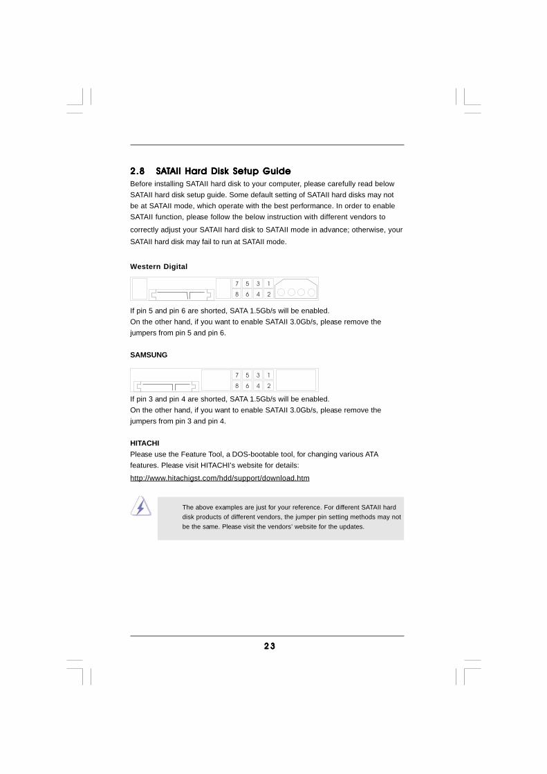
2.82.82.82.82.8 SASASASASATTTTTAII Hard Disk Setup GuideAII Hard Disk Setup GuideAII Hard Disk Setup GuideAII Hard Disk Setup GuideAII Hard Disk Setup GuideBefore installing SATAII hard disk to your computer, please carefully read belowSATAII hard disk setup guide. Some default setting of SATAII hard disks may notbe at SATAII mode, which operate with the best performance. In order to enableSATAII function, please follow the below instruction with different vendors to
correctly adjust your SATAII hard disk to SATAII mode in advance; otherwise, yourSATAII hard disk may fail to run at SATAII mode.
Western Digital
If pin 5 and pin 6 are shorted, SATA 1.5Gb/s will be enabled.On the other hand, if you want to enable SATAII 3.0Gb/s, please remove thejumpers from pin 5 and pin 6.
SAMSUNG
If pin 3 and pin 4 are shorted, SATA 1.5Gb/s will be enabled.On the other hand, if you want to enable SATAII 3.0Gb/s, please remove thejumpers from pin 3 and pin 4.
HITACHIPlease use the Feature Tool, a DOS-bootable tool, for changing various ATAfeatures. Please visit HITACHI’s website for details:
http://www.hitachigst.com/hdd/support/download.htm
1357
2468
1357
2468
The above examples are just for your reference. For different SATAII harddisk products of different vendors, the jumper pin setting methods may notbe the same. Please visit the vendors’ website for the updates.
2 42 42 42 42 4
2.92.92.92.92.9 Serial ASerial ASerial ASerial ASerial ATTTTTA (SAA (SAA (SAA (SAA (SATTTTTA) / Serial AA) / Serial AA) / Serial AA) / Serial AA) / Serial ATTTTTAII (SAAII (SAAII (SAAII (SAAII (SATTTTTAII) Hard DisksAII) Hard DisksAII) Hard DisksAII) Hard DisksAII) Hard Disks
InstallationInstallationInstallationInstallationInstallationThis motherboard adopts JMicron® JMB363 chipset that supports Serial ATAII(SATAII) hard disks. It also adopts VIA® VT8237A south bridge chipset thatsupports Serial ATA (SATA) hard disks, and supports RAID functions. You mayinstall SATA / SATAII hard disks on this motherboard for internal storage devices.This section will guide you to install the SATA / SATAII hard disks.
STEP 1: Install the SATA / SATAII hard disks into the drive bays of your chassis.STEP 2: Connect the SATA power cable to the SATA / SATAII hard disk.STEP 3: Connect one end of the SATA data cable to the motherboard’s SATA /
SATAII connector.STEP 4: Connect the other end of the SATA data cable to the SATA / SATAII hard
disk.
To create RAID with two HDDs, please insert the two HDDs simultaneously toeither SATA connectors (black) or SATAII connectors (red). If you insert one HDD toSATA connector and the other HDD to SATAII connector, you are not allowed tocreate RAID.
2.10 Hot Plug and Hot Swap F2.10 Hot Plug and Hot Swap F2.10 Hot Plug and Hot Swap F2.10 Hot Plug and Hot Swap F2.10 Hot Plug and Hot Swap Functions for SAunctions for SAunctions for SAunctions for SAunctions for SATTTTTA / SAA / SAA / SAA / SAA / SATTTTTAIIAIIAIIAIIAII
HDDsHDDsHDDsHDDsHDDsALiveSATA2-GLAN motherboard supports Hot Plug and Hot Swap functions forSATA / SATAII Devices.
NOTE
What is Hot Plug Function?If the SATA / SATAII HDDs are NOT set for RAID configuration, it is called“Hot Plug” for the action to insert and remove the SATA / SATAII HDDswhile the system is still power-on and in working condition.However, please note that it cannot perform Hot Plug if the OS has beeninstalled into the SATA / SATAII HDD.
What is Hot Swap Function?If SATA / SATAII HDDs are built as RAID1 then it is called “Hot Swap” forthe action to insert and remove the SATA / SATAII HDDs while the systemis still power-on and in working condition.

2 52 52 52 52 5
2.122.122.122.122.12 Installing WindowsInstalling WindowsInstalling WindowsInstalling WindowsInstalling Windows®®®®® 2000 / XP / XP 64-bit / Vista 2000 / XP / XP 64-bit / Vista 2000 / XP / XP 64-bit / Vista 2000 / XP / XP 64-bit / Vista 2000 / XP / XP 64-bit / VistaTMTMTMTMTM / / / / /
VistaVistaVistaVistaVistaTMTMTMTMTM 64-bit With RAID Functions 64-bit With RAID Functions 64-bit With RAID Functions 64-bit With RAID Functions 64-bit With RAID Functions
The installation procedures for Windows® VistaTM / VistaTM 64-bit are subjectto change. Please visit our website for the updates of Windows® VistaTM /VistaTM 64-bit driver and related information in the future.
2.112.112.112.112.11 Driver Installation Guide Driver Installation Guide Driver Installation Guide Driver Installation Guide Driver Installation GuideTo install the drivers to your system, please insert the support CD to your opticaldrive first. Then, the drivers compatible to your system can be auto-detected andlisted on the support CD driver page. Please follow the order from up to bottomside to install those required drivers. Therefore, the drivers you install can workproperly.
If you want to install Windows® 2000, XP, XP 64-bit, VistaTM or VistaTM 64-bit on yourSATA / SATAII HDDs with RAID functions, please follow below procedures accordingto the OS you install.
2.12.1 Installing Windows2.12.1 Installing Windows2.12.1 Installing Windows2.12.1 Installing Windows2.12.1 Installing Windows®®®®® 2000 / XP / XP 64-bit With RAID 2000 / XP / XP 64-bit With RAID 2000 / XP / XP 64-bit With RAID 2000 / XP / XP 64-bit With RAID 2000 / XP / XP 64-bit With RAID
Functions Functions Functions Functions FunctionsIf you want to install Windows® 2000, XP or XP 64-bit on your SATA / SATAII HDDswith RAID functions, please follow below steps.
STEP 1: Set up BIOS.A. Enter BIOS SETUP UTILITY Advanced screen IDE Configuration.B. If you plan to install Windows® 2000 / XP / XP 64-bit on VIA® SATA ports with RAID functions, please set the “SATA Operation Mode” option to [RAID]. If you plan to install Windows® 2000 / XP / XP 64-bit on JMicron® SATAII ports with RAID functions, please set the “PCIE-SATAII Operation Mode” option to [RAID].STEP 2: Make a SATA / SATAII driver diskette.A. Insert the ASRock Support CD into your optical drive to boot your system.B. During POST at the beginning of system boot-up, press <F11> key, and then a window for boot devices selection appears. Please select CD-ROM as the boot device.C. When you see the message on the screen, “Do you want to generate Serial ATA driver diskette [YN]?”, press <Y>.D. Then you will see these messages,
Please insert a diskette into the floppy drive.WARNING! Formatting the floppy diskette willlose ALL data in it!Start to format and copy files [YN]?Please insert a floppy diskette into the floppy drive, and press <Y>.
2 62 62 62 62 6
If you want to use “VIA RAID Tool” in Windows® environment, please installSATA drivers from the Support CD again so that “VIA RAID Tool” will beinstalled to your system as well. If you want to use “JMicron RAID Tool” inWindows® environment, please install SATAII drivers from the Support CDagain so that “JMicron RAID Tool” will be installed to your system as well.
NOTE. After the installation of Windows® 2000 / XP / XP 64-bit OS and RAID utility, if youwant to manage RAID functions, please refer to the Windows RAID installationguide of the document in the following path in the Support CD:.. \ RAID Installation Guide
E. The system will start to format the floppy diskette and copy SATA / SATAII drivers into the floppy diskette.STEP 3: Use “RAID Installation Guide” to set RAID configuration.Before you start to configure RAID function, you need to check the RAID installationguide in the Support CD for proper configuration. Please refer to the BIOS RAIDinstallation guide of the document in the following path in the Support CD:.. \ RAID Installation GuideSTEP 4: Install Windows® 2000 / XP / XP 64-bit OS on your system.After making a SATA / SATAII driver diskette and set RAID configuration, you canstart to install Windows® 2000 / XP / XP 64-bit on your system. At the beginning ofWindows® setup, press F6 to install a third-party RAID driver. When prompted, insertthe SATA / SATAII driver diskette containing VIA® and JMicron® RAID driver. Afterreading the floppy disk, the driver will be presented. Select your required driver toinstall according to the SATA / SATAII controller support vendor and the OS youinstall. The driver options are as below:1. VIA VT8251/8237/8237A/6421/6410 SATA RAID Controller (Windows XP/SRV2003)2. VIA VT8251/8237/8237A/6421/6410 SATA RAID Controller (Windows 2K)3. VIA VT8251/8237/8237A/6421/6410 SATA RAID Controller (Windows NT4)4. JMicron JMB36X RAID Controller (Windows 2K/XP/2003)5. JMicron JMB36X AHCI Controller (Windows 2K/XP/2003)If you insert HDDs to VIA® SATA connectors (black), please choose item 1, 2, or 3according to the OS you install. If you insert HDDs to JMicron® SATAII connectors(red), please choose item 4. You can also specify twice to load both two drivers ifyou plan to create RAID on two SATA HDDs and two SATAII HDDs, but please notethat the two SATA HDDs and two SATAII HDDs provide separated RAID functions.

2 72 72 72 72 7
2.12.2 Installing Windows2.12.2 Installing Windows2.12.2 Installing Windows2.12.2 Installing Windows2.12.2 Installing Windows®®®®® Vista Vista Vista Vista VistaTMTMTMTMTM / Vista / Vista / Vista / Vista / VistaTMTMTMTMTM 64-bit With RAID 64-bit With RAID 64-bit With RAID 64-bit With RAID 64-bit With RAID
Functions Functions Functions Functions FunctionsIf you want to install Windows® VistaTM or VistaTM 64-bit on your SATA / SATAII HDDswith RAID functions, please follow below steps.
STEP 1: Set up BIOS.A. Enter BIOS SETUP UTILITY Advanced screen IDE Configuration.B. If you plan to install Windows® VistaTM / VistaTM 64-bit on VIA® SATA ports with RAID functions, please set the “SATA Operation Mode” option to [RAID]. If you plan to install Windows® VistaTM / VistaTM 64-bit on JMicron® SATAII ports with RAID functions, please set the “PCIE-SATAII Operation Mode” option to [RAID].STEP 2: Make a SATAII driver diskette. (For JMicron® SATAII ports in RAID
mode only.)If you set “PCIE-SATAII Operation Mode” to [RAID] mode, and plan to installWindows® VistaTM / VistaTM 64-bit on JMicron® SATAII HDDs, please refer to step 2on page 25 for detailed procedures of making a SATAII driver diskette. Otherwise,please skip this step.STEP 3: Use “RAID Installation Guide” to set RAID configuration.Before you start to configure RAID function, you need to check the RAID installationguide in the Support CD for proper configuration. Please refer to the BIOS RAIDinstallation guide of the document in the following path in the Support CD:.. \ RAID Installation GuideSTEP 4: Install Windows® VistaTM / VistaTM 64-bit OS on your system.Insert the Windows® VistaTM / VistaTM 64-bit optical disk into the optical drive to bootyour system, and follow the instruction to install Windows® VistaTM / VistaTM 64-bitOS on your system.If you plan to install Windows® VistaTM / VistaTM 64-bit on VIA® SATA HDDs, when yousee “Where do you want to install Windows?” page, please insert the ASRockSupport CD into your optical drive, and click the “Load Driver” button on the left on thebottom to load the VIA® RAID drivers. VIA® RAID drivers are in the following path inour Support CD:.. \ I386 \ NT5 (For Windows® VistaTM OS).. \ AMD64 \ 2003x64 (For Windows® VistaTM 64-bit OS)If you plan to install Windows® VistaTM / VistaTM 64-bit on JMicron® SATAII HDDs,when you see “Where do you want to install Windows?” page, please click the“Load Driver” button on the left on the bottom to load the JMicron® RAID drivers fromthe SATAII driver diskette you just made.After that, please insert Windows® VistaTM / VistaTM 64-bit optical disk into the opticaldrive again to continue the installation.

2 82 82 82 82 8
2.132.132.132.132.13 Installing WindowsInstalling WindowsInstalling WindowsInstalling WindowsInstalling Windows®®®®® 2000 / XP / XP 64-bit / Vista 2000 / XP / XP 64-bit / Vista 2000 / XP / XP 64-bit / Vista 2000 / XP / XP 64-bit / Vista 2000 / XP / XP 64-bit / VistaTMTMTMTMTM / / / / /
VistaVistaVistaVistaVistaTMTMTMTMTM 64-bit Without RAID Functions 64-bit Without RAID Functions 64-bit Without RAID Functions 64-bit Without RAID Functions 64-bit Without RAID Functions
If you want to install Windows® 2000, XP, XP 64-bit, VistaTM or VistaTM 64-bit on yourSATA / SATAII HDDs without RAID functions, please follow below proceduresaccording to the OS you install.
The installation procedures for Windows® VistaTM / VistaTM 64-bit are subjectto change. Please visit our website for the updates of Windows® VistaTM /VistaTM 64-bit driver and related information in the future.
2.13.1 Installing Windows2.13.1 Installing Windows2.13.1 Installing Windows2.13.1 Installing Windows2.13.1 Installing Windows®®®®® 2000 / XP / XP 64-bit Without 2000 / XP / XP 64-bit Without 2000 / XP / XP 64-bit Without 2000 / XP / XP 64-bit Without 2000 / XP / XP 64-bit Without
RAID Functions RAID Functions RAID Functions RAID Functions RAID FunctionsIf you want to install Windows® 2000, XP or XP 64-bit on your SATA / SATAII HDDswithout RAID functions, please follow below steps.
STEP 1: Set up BIOS.A. Enter BIOS SETUP UTILITY Advanced screen IDE Configuration.B. If you plan to install Windows® 2000 / XP / XP 64-bit on VIA® SATA ports without RAID functions, please set the “SATA Operation Mode” option to [non-RAID]. If you plan to install Windows® 2000 / XP / XP 64-bit on JMicron® SATAII ports without RAID functions, please set the “PCIE-SATAII Operation Mode” option to [IDE] or [AHCI].STEP 2: Make a SATAII driver diskette. (For JMicron® SATAII ports in AHCI
mode only.)If you set “PCIE-SATAII Operation Mode” to [AHCI] mode, and plan to installWindows® 2000 / XP / XP 64-bit on JMicron® SATAII HDDs, please refer to step 2on page 25 for detailed procedures of making a SATAII driver diskette. Otherwise,please skip this step.STEP 3: Install Windows® 2000 / XP / XP-64bit OS on your system.After above steps, you can start to install Windows® 2000 / XP / XP 64-bit onyour system. (If you plan to install Windows® 2000 / XP / XP 64-bit on JMicron®
SATAII ports in AHCI mode, at the beginning of Windows® setup, press F6 to installa third-party AHCI driver. When prompted, insert the SATAII driver diskettecontaining JMicron® AHCI driver. After reading the floppy disk, the driver will bepresented. The driver options are as below:1. VIA VT8251/8237/8237A/6421/6410 SATA RAID Controller (Windows XP/SRV2003)2. VIA VT8251/8237/8237A/6421/6410 SATA RAID Controller (Windows 2K)3. VIA VT8251/8237/8237A/6421/6410 SATA RAID Controller (Windows NT4)4. JMicron JMB36X RAID Controller (Windows 2K/XP/2003)5. JMicron JMB36X AHCI Controller (Windows 2K/XP/2003)Please select item 5 to install Windows® OS for JMicron® SATAII ports in AHCI mode.)
2 92 92 92 92 9
2.13.2 Installing Windows2.13.2 Installing Windows2.13.2 Installing Windows2.13.2 Installing Windows2.13.2 Installing Windows®®®®® Vista Vista Vista Vista VistaTMTMTMTMTM / Vista / Vista / Vista / Vista / VistaTMTMTMTMTM 64-bit Without 64-bit Without 64-bit Without 64-bit Without 64-bit Without
RAID Functions RAID Functions RAID Functions RAID Functions RAID FunctionsIf you want to install Windows® VistaTM or VistaTM 64-bit on your SATA / SATAII HDDswithout RAID functions, please follow below steps.
STEP 1: Set up BIOS.A. Enter BIOS SETUP UTILITY Advanced screen IDE Configuration.B. If you plan to install Windows® VistaTM / VistaTM 64-bit on VIA® SATA ports without RAID functions, please set the “SATA Operation Mode” option to [non-RAID]. If you plan to install Windows® VistaTM / VistaTM 64-bit on JMicron®
SATAII ports without RAID functions, please set the “PCIE-SATAII Operation Mode” option to [IDE] or [AHCI].STEP 2: Install Windows® VistaTM / VistaTM 64bit OS on your system.You can start to install Windows® VistaTM / VistaTM 64-bit on your system.
Please refer to the warning on page 7 for the possible overclocking risk beforeyou apply Untied Overclocking Technology.
2.142.142.142.142.14 Untied Overclocking TUntied Overclocking TUntied Overclocking TUntied Overclocking TUntied Overclocking TechnologyechnologyechnologyechnologyechnologyThis motherboard supports Untied Overclocking Technology, which means duringoverclocking, FSB enjoys better margin due to fixed PCI / PCIE buses. You may set“CPU Host Frequency” option of BIOS setup to [Auto], which will show you the actualCPU host frequency in the following item. Therefore, CPU FSB is untied duringoverclocking, but PCI / PCIE buses are in the fixed mode so that FSB can operateunder a more stable overclocking environment.
3 03 03 03 03 0
3.3.3.3.3. BIOS SETUP UTILITYBIOS SETUP UTILITYBIOS SETUP UTILITYBIOS SETUP UTILITYBIOS SETUP UTILITY3.1 Introduction3.1 Introduction3.1 Introduction3.1 Introduction3.1 IntroductionThis section explains how to use the BIOS SETUP UTILITY to configure your system.The Flash Memory on the motherboard stores the BIOS SETUP UTILITY. You may runthe BIOS SETUP UTILITY when you start up the computer. Please press <F2> duringthe Power-On-Self-Test (POST) to enter the BIOS SETUP UTILITY, otherwise, POSTwill continue with its test routines.If you wish to enter the BIOS SETUP UTILITY after POST, restart the system bypressing <Ctl> + <Alt> + <Delete>, or by pressing the reset button on the systemchassis. You may also restart by turning the system off and then back on.
Because the BIOS software is constantly being updated, the followingBIOS setup screens and descriptions are for reference purpose only,and they may not exactly match what you see on your screen.
3.1.13.1.13.1.13.1.13.1.1 BIOS Menu BarBIOS Menu BarBIOS Menu BarBIOS Menu BarBIOS Menu BarThe top of the screen has a menu bar with the following selections:Main To set up the system time/date informationAdvanced To set up the advanced BIOS featuresH/W Monitor To display current hardware statusBoot To set up the default system device to locate and load the
Operating SystemSecurity To set up the security featuresExit To exit the current screen or the BIOS SETUP UTILITYUse < > key or < > key to choose among the selections on the menu bar,and then press <Enter> to get into the sub screen.

3 13 13 13 13 1
3.1.23.1.23.1.23.1.23.1.2 Navigation KeysNavigation KeysNavigation KeysNavigation KeysNavigation KeysPlease check the following table for the function description of each navigationkey.
Navigation Key(s) Function Description / Moves cursor left or right to select Screens / Moves cursor up or down to select items + / - To change option for the selected items<Enter> To bring up the selected screen<F1> To display the General Help Screen<F9> To load optimal default values for all the settings<F10> To save changes and exit the BIOS SETUP UTILITY<ESC> To jump to the Exit Screen or exit the current screen
3.23.23.23.23.2 Main ScreenMain ScreenMain ScreenMain ScreenMain ScreenWhen you enter the BIOS SETUP UTILITY, the Main screen will appear and displaythe system overview
System Time [Hour:Minute:Second]Use this item to specify the system time.
System Date [Day Month/Date/Year]Use this item to specify the system date.
BIOS SETUP UTILITY
Main Advanced H/W Monitor Boot Security Exit
System Overview
System Time
System Date[ :00:09][Mon 06/26/2006]
Use [Enter], [TAB]or [SHIFT-TAB] toselect a field.
Use [+] or [-] toconfigure system Time.
Select ScreenSelect Item
+- Change FieldTab Select FieldF1 General HelpF9 Load DefaultsF10 Save and ExitESC Exit
BIOS VersionProcessor Type
Processor SpeedMicrocode UpdateL1 Cache SizeL2 Cache Size
Total Memory
DDRII 1DDRII 2DDRII 3DDRII 4
: ALiveSATA2-GLAN BIOS P1.0: AMD Athlon(tm) 64 Processor 3500+
(64 bit supported): 2200 MHz: 10FF0/41: 128KB: 1024KB
: 512MBDual-Channel Memory Mode
: 256MB/266MHz (DDRII533): 256MB/266MHz (DDRII533): None: None
v02.54 (C) Copyright 1985-2003, American Megatrends, Inc.
17
3 23 23 23 23 2
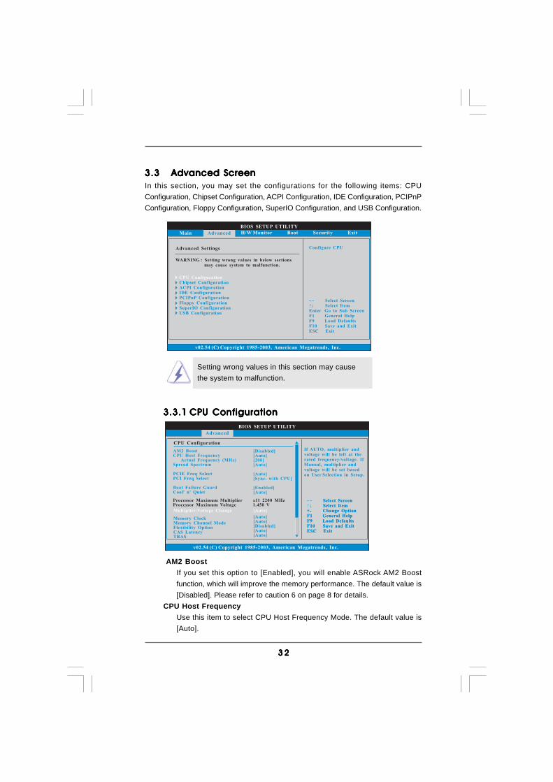
3.33.33.33.33.3 Advanced ScreenAdvanced ScreenAdvanced ScreenAdvanced ScreenAdvanced ScreenIn this section, you may set the configurations for the following items: CPUConfiguration, Chipset Configuration, ACPI Configuration, IDE Configuration, PCIPnPConfiguration, Floppy Configuration, SuperIO Configuration, and USB Configuration.
Setting wrong values in this section may causethe system to malfunction.
BIOS SETUP UTILITY
Main H/W Monitor Boot Security Exit
Advanced Settings
WARNING : Setting wrong values in below sectionsmay cause system to malfunction.
Configure CPU
Select ScreenSelect Item
Enter Go to Sub ScreenF1 General HelpF9 Load DefaultsF10 Save and ExitESC Exit
v02.54 (C) Copyright 1985-2003, American Megatrends, Inc.
Advanced
CPU ConfigurationChipset Configuration
IDE ConfigurationPCIPnP ConfigurationFloppy ConfigurationSuperIO ConfigurationUSB Configuration
ACPI Configuration
BIOS SETUP UTILITY
CPU Configuration
Select ScreenSelect Item
+- Change OptionF1 General HelpF9 Load DefaultsF10 Save and ExitESC Exit
v02.54 (C) Copyright 1985-2003, American Megatrends, Inc.
Advanced
Select ScreenSelect Item
+- Change OptionF1 General HelpF9 Load DefaultsF10 Save and ExitESC Exit
[Disabled][Auto][200][Auto]
[Auto][Sync. with CPU]
[Enabled][Auto]
AM2 BoostCPU Host Frequency
Actual Frequency (MHz)Spread Spectrum
Boot Failure Guard
PCIE Freq SelectPCI Freq Select
Cool' n' Quiet
Memory ClockMemory Channel ModeFlexibility OptionCAS LatencyTRAS
[Auto][Auto]
[Auto][Auto]
[Disabled]
If AUTO, multiplier andvoltage will be left at therated frequency/voltage. IfManual,
will be set basedon User Selection in Setup.
multiplier andvoltage
Processor Maximum MultiplierProcessor Maximum Voltage
x11 2200 MHz1.450 V
Multiplier/Voltage Change [Auto]
3.3.13.3.13.3.13.3.13.3.1 CPU ConfigurationCPU ConfigurationCPU ConfigurationCPU ConfigurationCPU Configuration
AM2 BoostIf you set this option to [Enabled], you will enable ASRock AM2 Boostfunction, which will improve the memory performance. The default value is[Disabled]. Please refer to caution 6 on page 8 for details.
CPU Host FrequencyUse this item to select CPU Host Frequency Mode. The default value is[Auto].
3 33 33 33 33 3
BIOS SETUP UTILITY
BIOS SETUP UTILITY
CPU Configuration
Select ScreenSelect Item
+- Change OptionF1 General HelpF9 Load DefaultsF10 Save and ExitESC Exit
v02.54 (C) Copyright 1985-2003, American Megatrends, Inc.
Advanced
Select ScreenSelect Item
+- Change OptionF1 General HelpF9 Load DefaultsF10 Save and ExitESC Exit
Memory ClockMemory Channel ModeFlexibility Option
[Auto][Auto][Disabled]
If AUTO, multiplier andvoltage will be left at therated frequency/voltage. IfManual,
will be set basedon User Selection in Setup.
multiplier andvoltage
BIOS SETUP UTILITY
Processor Maximum MultiplierProcessor Maximum Voltage
x11 2200 MHz1.450 V
Multiplier/Voltage Change [Manual]Processor MultiplierProcessor Voltage
[x11 2200 MHz][1.450V]
[Disabled][Auto][200][Auto]
[Auto][Sync. with CPU]
[Enabled][Auto]
AM2 BoostCPU Host Frequency
Actual Frequency (MHz)Spread Spectrum
Boot Failure Guard
PCIE Freq SelectPCI Freq Select
Cool' n' Quiet
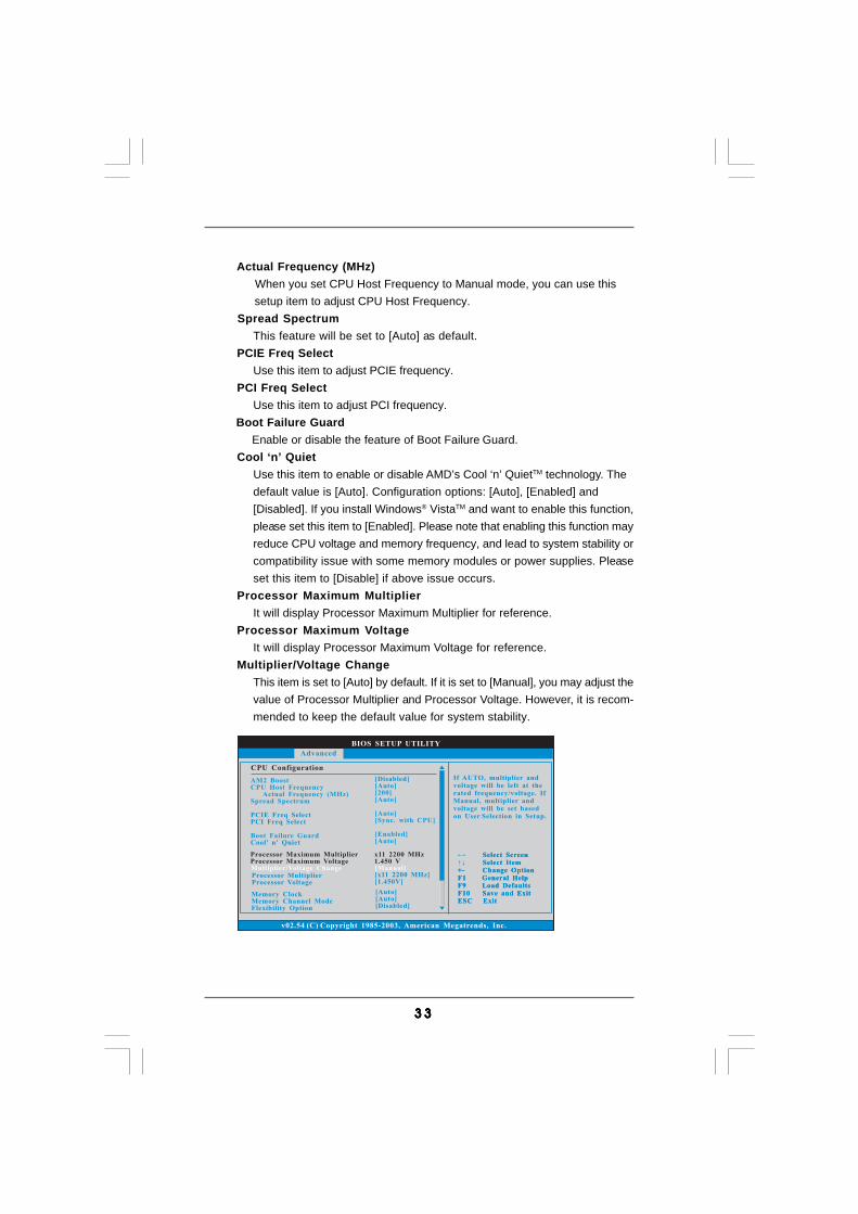
Actual Frequency (MHz) When you set CPU Host Frequency to Manual mode, you can use this setup item to adjust CPU Host Frequency. Spread Spectrum
This feature will be set to [Auto] as default.PCIE Freq Select
Use this item to adjust PCIE frequency.PCI Freq Select
Use this item to adjust PCI frequency. Boot Failure Guard Enable or disable the feature of Boot Failure Guard.
Cool ‘n’ QuietUse this item to enable or disable AMD’s Cool ‘n’ QuietTM technology. Thedefault value is [Auto]. Configuration options: [Auto], [Enabled] and[Disabled]. If you install Windows® VistaTM and want to enable this function,please set this item to [Enabled]. Please note that enabling this function mayreduce CPU voltage and memory frequency, and lead to system stability orcompatibility issue with some memory modules or power supplies. Pleaseset this item to [Disable] if above issue occurs.
Processor Maximum MultiplierIt will display Processor Maximum Multiplier for reference.
Processor Maximum VoltageIt will display Processor Maximum Voltage for reference.
Multiplier/Voltage ChangeThis item is set to [Auto] by default. If it is set to [Manual], you may adjust thevalue of Processor Multiplier and Processor Voltage. However, it is recom-mended to keep the default value for system stability.
3 43 43 43 43 4
Processor MultiplierThis item will show when “Multiplier/Voltage Change” is set to [Manual];otherwise, it will be hidden. The range of the value depends on the CPUyou adopt on this motherboard. However, for system stability, it is notrecommended to adjust the value of this item.
Processor VoltageThis item will show when “Multiplier/Voltage Change” is set to [Manual];otherwise, it will be hidden. The range of the value depends on the CPUyou adopt on this motherboard. However, for safety and system stability,it is not recommended to adjust the value of this item.
Memory ClockThis item can be set by the code using [Auto]. You can set one of thestandard values as listed: [200MHz (DDRII 400)], [266MHz (DDRII 533)],[333MHz (DDRII 667)], and [400MHz (DDRII 800)].
Memory Channel ModeThis item is set to [Auto] by default. If it is set to [Single Channel], you canforce the Memory Channel Mode to Single Channel Mode. Configurationoptions: [Auto], [Single Channel].
Flexibility OptionThe default value of this option is [Disabled]. It will allow better tolerance formemory compatibility when it is set to [Enabled].
CAS LatencyUse this item to adjust the means of memory accessing. Configurationoptions: [Auto], [3T], [4T], and [5T].
TRASUse this to adjust TRAS values. Configuration options: [Auto], [5T], [6T],[7T], [8T], [9T], [10T], [11T], [12T], [13T], [14T], [15T], [16T], [17T], [18T].
TRPUse this to adjust TRP values. Configuration options: [Auto], [3CLK], [4CLK],[5CLK], and [6CLK].
TRCDUse this to adjust TRCD values. Configuration options: [Auto], [3CLK], [4CLK],[5CLK], and [6CLK].
TRRDUse this to adjust TRRD values. the default value is [Auto].
TRCUse this to adjust TRC values. The default value is [Auto].
MA TimingUse this to adjust values for MA timing. Configuration options: [Auto], [2T],[1T]. The default value is [Auto].
3 53 53 53 53 5
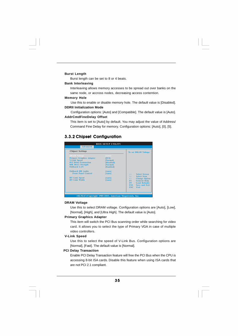
DRAM VoltageUse this to select DRAM voltage. Configuration options are [Auto], [Low],[Normal], [High], and [Ultra High]. The default value is [Auto].
Primary Graphics AdapterThis item will switch the PCI Bus scanning order while searching for videocard. It allows you to select the type of Primary VGA in case of multiplevideo controllers.
V-Link SpeedUse this to select the speed of V-Link Bus. Configuration options are[Normal], [Fast]. The default value is [Normal].
PCI Delay TransactionEnable PCI Delay Transaction feature will free the PCI Bus when the CPU isaccessing 8-bit ISA cards. Disable this feature when using ISA cards thatare not PCI 2.1 compliant.
BIOS SETUP UTILITY
v02.54 (C) Copyright 1985-2003, American Megatrends, Inc.
Chipset Settings
Primary Graphics AdapterV-Link SpeedPCI Delay TransactionIDE Drive StrengthOnBoard LAN
OnBoard HD AudioFront Panel Control
HT Link SpeedHT Link Width
[PCI]
[Auto]
[Auto]
[Normal][Disabled][Normal][Enabled]
[Auto]
[Auto]
Select ScreenSelect Item
+ - Change OptionF1 General Help
F10 Save and ExitESC Exit
F9 Load Defaults
To set DRAM Voltage.
Advanced
DRAM Voltage [Auto]
Burst LengthBurst length can be set to 8 or 4 beats.
Bank InterleavingInterleaving allows memory accesses to be spread out over banks on thesame node, or accross nodes, decreasing access contention.
Memory Hole Use this to enable or disable memory hole. The default value is [Disabled].
DDRII Initialization Mode Configuration options: [Auto] and [Compatible]. The default value is [Auto].
AddrCmdFineDelay OffsetThis item is set to [Auto] by default. You may adjust the value of Address/Command Fine Delay for memory. Configuration options: [Auto], [0], [5].
3.3.23.3.23.3.23.3.23.3.2 Chipset ConfigurationChipset ConfigurationChipset ConfigurationChipset ConfigurationChipset Configuration
3 63 63 63 63 6
IDE Driving StrengthUse this item to select drive strength of the onboard IDE controller. Configu-ration options: [Low], [Normal], [High] or [Ultra High]. The default value is[Normal].
OnBoard LANThis allows you to enable or disable the onboard LAN feature.
OnBoard HD AudioSelect [Auto], [Enabled] or [Disabled] for the onboard HD Audio feature. Ifyou select [Auto], the onboard HD Audio will be disabled when PCI SoundCard is plugged.
Front Panel ControlSelect [Auto], [Enabled] or [Disabled] for the onboard HD Audio Front Panel.
HT Link SpeedYou may set the HyperTransport speed as [Auto], [200 MHz], [400 MHz],[600 MHz], [800 MHz], or [1000 MHz]. The default value is [Auto].
HT Link WidthYou may set the HyperTransport width as [8 bit], [16 bit] or [Auto]. Thedefault value is [Auto].
3 73 73 73 73 7
BIOS SETUP UTILITY
ACPI Settings Select auto-detect ordisable the STRfeature.
Select ScreenSelect Item
+- Change OptionF1 General HelpF9 Load DefaultsF10 Save and ExitESC Exit
v02.54 (C) Copyright 1985-2003, American Megatrends, Inc.
Advanced
Suspend To RAMAway Mode Support
Restore on AC / Power LossRing-In Power OnPCI Devices Power OnPS / 2 Keyboard Power OnRTC Alarm Power On
[Disabled][Disabled]
[Power Off][Disabled][Disabled][Disabled][Disabled]
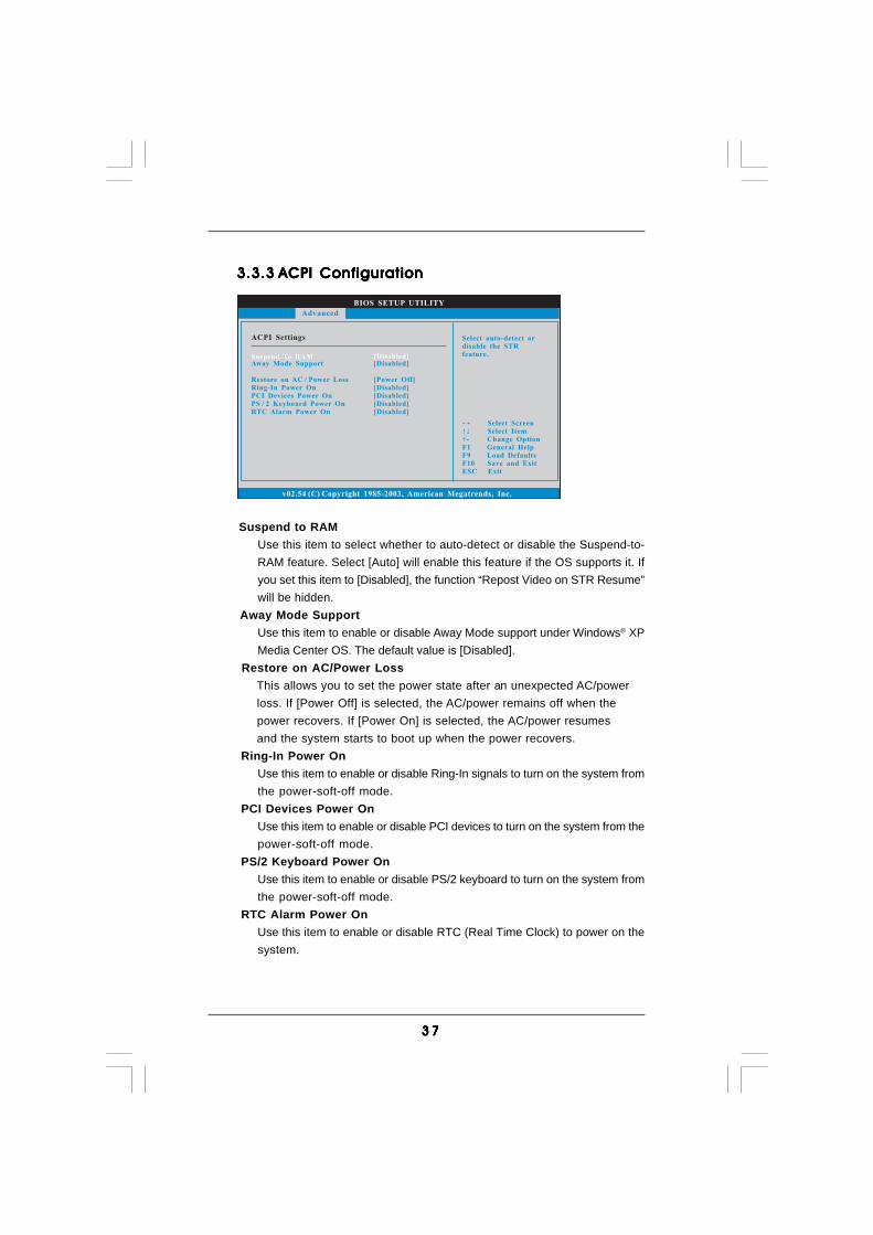
3.3.33.3.33.3.33.3.33.3.3 ACPI ConfigurationACPI ConfigurationACPI ConfigurationACPI ConfigurationACPI Configuration
Suspend to RAMUse this item to select whether to auto-detect or disable the Suspend-to-RAM feature. Select [Auto] will enable this feature if the OS supports it. Ifyou set this item to [Disabled], the function “Repost Video on STR Resume”will be hidden.
Away Mode SupportUse this item to enable or disable Away Mode support under Windows® XPMedia Center OS. The default value is [Disabled].
Restore on AC/Power Loss This allows you to set the power state after an unexpected AC/power loss. If [Power Off] is selected, the AC/power remains off when the power recovers. If [Power On] is selected, the AC/power resumes and the system starts to boot up when the power recovers.
Ring-In Power OnUse this item to enable or disable Ring-In signals to turn on the system fromthe power-soft-off mode.
PCI Devices Power OnUse this item to enable or disable PCI devices to turn on the system from thepower-soft-off mode.
PS/2 Keyboard Power OnUse this item to enable or disable PS/2 keyboard to turn on the system fromthe power-soft-off mode.
RTC Alarm Power OnUse this item to enable or disable RTC (Real Time Clock) to power on thesystem.
3 83 83 83 83 8
BIOS SETUP UTILITY
IDE Configuration
v02.54 (C) Copyright 1985-2005, American Megatrends, Inc.
Advanced
OnBoard IDE Controller
Primary IDE MasterPrimary IDE SlaveSecondary IDE MasterSecondary IDE SlaveSATA1SATA2SATAII_1SATAII_2
[Enabled]
[Hard Disk][Not Detected][ATAPI CDROM][Not Detected][Not Detected][Not Detected][Not Detected][Not Detected]
Select ScreenSelect Item
+- Change OptionF1 General HelpF9 Load DefaultsF10 Save and ExitESC Exit
Select ScreenSelect Item
+- Change OptionF1 General HelpF9 Load DefaultsF10 Save and ExitESC Exit
Use this item to enable ordisable IDE controller.
SATA Operation ModeVIA SATA Raid UtilityOnBoard SATAII Controller
PCIE-SATAII Operation Mode
[RAID][Enabled][Enabled][IDE]
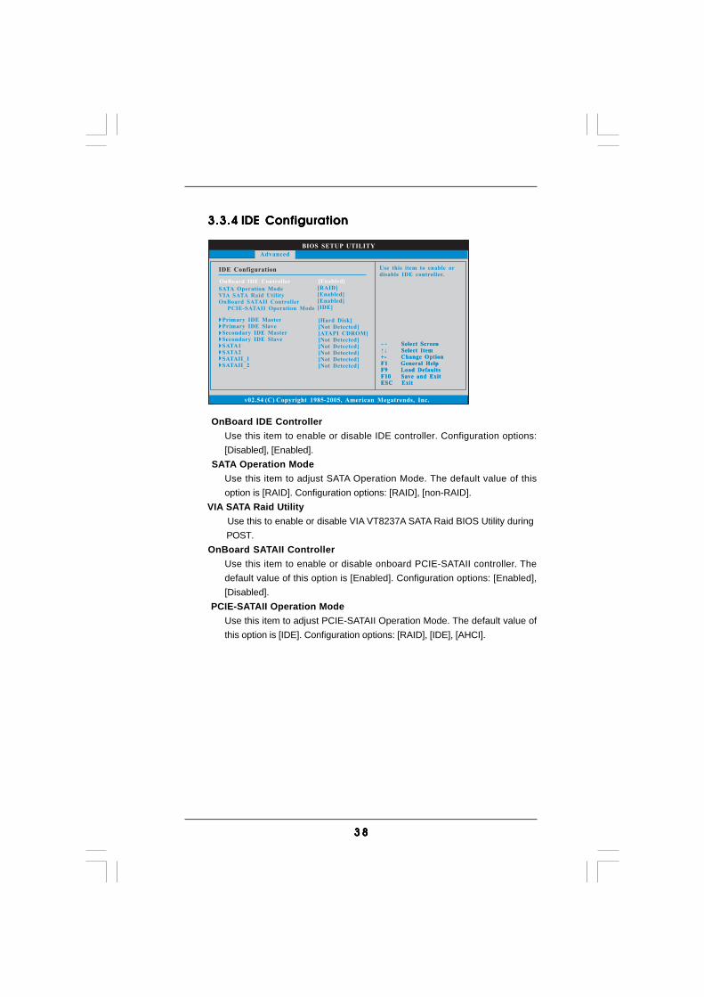
3.3.43.3.43.3.43.3.43.3.4 IDE ConfigurationIDE ConfigurationIDE ConfigurationIDE ConfigurationIDE Configuration
OnBoard IDE ControllerUse this item to enable or disable IDE controller. Configuration options:[Disabled], [Enabled].
SATA Operation ModeUse this item to adjust SATA Operation Mode. The default value of thisoption is [RAID]. Configuration options: [RAID], [non-RAID].
VIA SATA Raid Utility Use this to enable or disable VIA VT8237A SATA Raid BIOS Utility during POST.
OnBoard SATAII ControllerUse this item to enable or disable onboard PCIE-SATAII controller. Thedefault value of this option is [Enabled]. Configuration options: [Enabled],[Disabled].
PCIE-SATAII Operation ModeUse this item to adjust PCIE-SATAII Operation Mode. The default value ofthis option is [IDE]. Configuration options: [RAID], [IDE], [AHCI].

3 93 93 93 93 9
TYPEUse this item to configure the type of the IDE device that you specify.Configuration options: [Not Installed], [Auto], [CD/DVD], and [ARMD].[Not Installed]: Select [Not Installed] to disable the use of IDE device.[Auto]: Select [Auto] to automatically detect the hard disk drive.
After selecting the hard disk information into BIOS, use a diskutility, such as FDISK, to partition and format the new IDE harddisk drives. This is necessary so that you can write or readdata from the hard disk. Make sure to set the partition of thePrimary IDE hard disk drives to active.
[CD/DVD]: This is used for IDE CD/DVD drives.[ARMD]: This is used for IDE ARMD (ATAPI Removable Media Device),
such as MO.LBA/Large Mode
Use this item to select the LBA/Large mode for a hard disk > 512 MB underDOS and Windows; for Netware and UNIX user, select [Disabled] todisable the LBA/Large mode.
Block (Multi-Sector Transfer)The default value of this item is [Auto]. If this feature is enabled, it willenhance hard disk performance by reading or writing more data duringeach transfer.
BIOS SETUP UTILITY
Primary IDE Master Select the typeof device connectedto the system.
Select ScreenSelect Item
+- Change OptionF1 General HelpF9 Load DefaultsF10 Save and ExitESC Exit
v02.54 (C) Copyright 1985-2003, American Megatrends, Inc.
Advanced
Type
LBA/Large ModeBlock (Multi-Sector Transfer)PIO ModeDMA ModeS . M . A . R . T .32Bit Data Transfer
[Auto]
[Auto][Auto][Auto][Auto][Disabled][Disabled]
DeviceVendorSizeLBA ModeBlock ModePIO ModeAsync DMAUltra DMAS.M.A.R.T.
:Hard Disk:ST340014A:40.0 GB:Supported:16Sectors:4:MultiWord DMA-2:Ultra DMA-5:Supported
IDE Device ConfigurationYou may set the IDE configuration for the device that you specify. We willuse the “Primary IDE Master” as the example in the following instruction,which can be applied to the configurations of “Primary IDE Slave”, “Sec-ondary IDE Master”, and “Secondary IDE Slave” as well.
4 04 04 04 04 0
PIO ModeUse this item to set the PIO mode to enhance hard disk performance byoptimizing the hard disk timing.
DMA ModeDMA capability allows the improved transfer-speed and data-integrity forcompatible IDE devices.
S.M.A.R.T.Use this item to enable or disable the S.M.A.R.T. (Self-Monitoring, Analysis,and Reporting Technology) feature. Configuration options: [Disabled], [Auto],[Enabled].
32-Bit Data TransferUse this item to enable 32-bit access to maximize the IDE hard disk datatransfer rate.
4 14 14 14 14 1
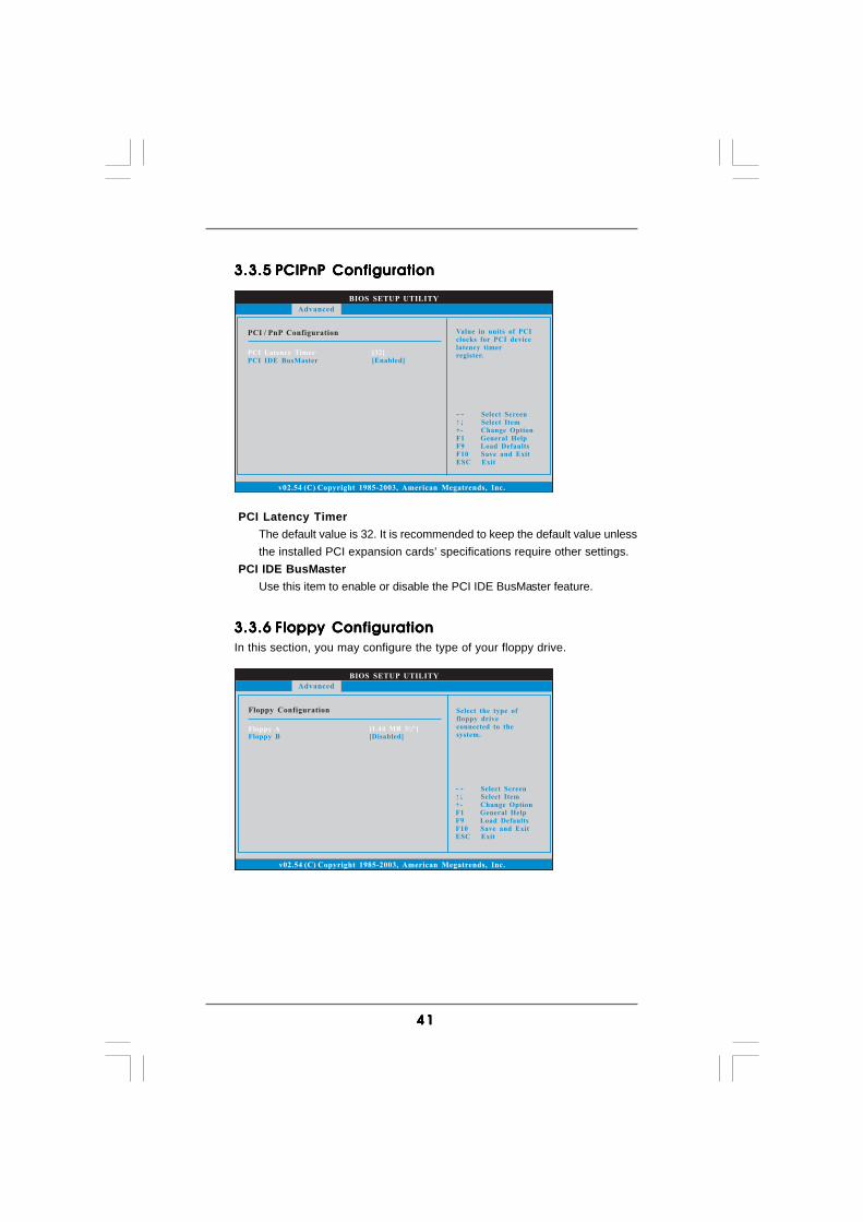
3.3.53.3.53.3.53.3.53.3.5 PCIPnP ConfigurationPCIPnP ConfigurationPCIPnP ConfigurationPCIPnP ConfigurationPCIPnP Configuration
PCI Latency TimerThe default value is 32. It is recommended to keep the default value unlessthe installed PCI expansion cards’ specifications require other settings.
PCI IDE BusMasterUse this item to enable or disable the PCI IDE BusMaster feature.
3.3.63.3.63.3.63.3.63.3.6 Floppy ConfigurationFloppy ConfigurationFloppy ConfigurationFloppy ConfigurationFloppy ConfigurationIn this section, you may configure the type of your floppy drive.
BIOS SETUP UTILITY
PCI / PnP Configuration Value in units of PCIclocks for PCI devicelatency timerregister.
Select ScreenSelect Item
+- Change OptionF1 General HelpF9 Load DefaultsF10 Save and ExitESC Exit
v02.54 (C) Copyright 1985-2003, American Megatrends, Inc.
PCI Latency TimerPCI IDE BusMaster
[32][Enabled]
Advanced
BIOS SETUP UTILITY
Floppy Configuration Select the type offloppy driveconnected to thesystem.
Select ScreenSelect Item
+- Change OptionF1 General HelpF9 Load DefaultsF10 Save and ExitESC Exit
v02.54 (C) Copyright 1985-2003, American Megatrends, Inc.
Advanced
Floppy AFloppy B
[1.44 MB 3 "][Disabled]
12
4 24 24 24 24 2
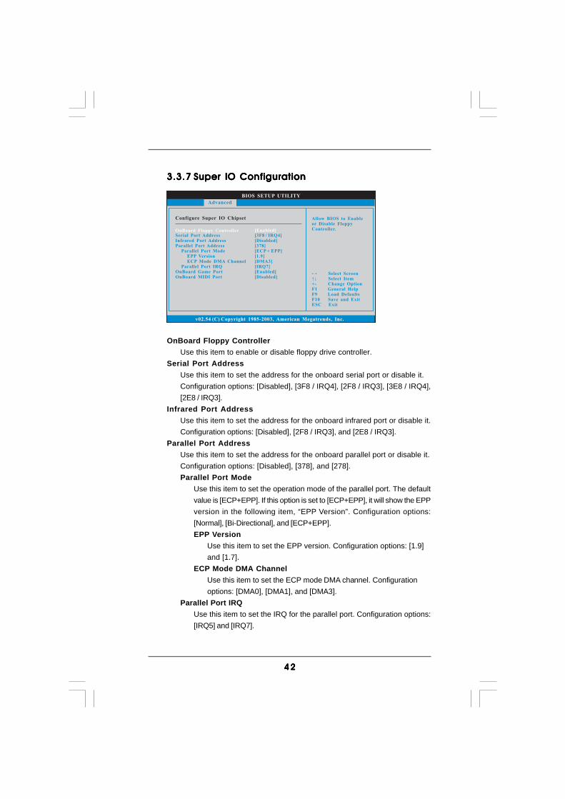
3.3.73.3.73.3.73.3.73.3.7 Super IO ConfigurationSuper IO ConfigurationSuper IO ConfigurationSuper IO ConfigurationSuper IO Configuration
OnBoard Floppy ControllerUse this item to enable or disable floppy drive controller.
Serial Port AddressUse this item to set the address for the onboard serial port or disable it.Configuration options: [Disabled], [3F8 / IRQ4], [2F8 / IRQ3], [3E8 / IRQ4],[2E8 / IRQ3].
Infrared Port AddressUse this item to set the address for the onboard infrared port or disable it.Configuration options: [Disabled], [2F8 / IRQ3], and [2E8 / IRQ3].
Parallel Port AddressUse this item to set the address for the onboard parallel port or disable it.Configuration options: [Disabled], [378], and [278].Parallel Port Mode
Use this item to set the operation mode of the parallel port. The defaultvalue is [ECP+EPP]. If this option is set to [ECP+EPP], it will show the EPPversion in the following item, “EPP Version”. Configuration options:[Normal], [Bi-Directional], and [ECP+EPP].EPP Version
Use this item to set the EPP version. Configuration options: [1.9]and [1.7].
ECP Mode DMA ChannelUse this item to set the ECP mode DMA channel. Configurationoptions: [DMA0], [DMA1], and [DMA3].
Parallel Port IRQUse this item to set the IRQ for the parallel port. Configuration options:[IRQ5] and [IRQ7].
BIOS SETUP UTILITY
Configure Super IO Chipset Allow BIOS to Enableor Disable FloppyController.
Select ScreenSelect Item
+- Change OptionF1 General HelpF9 Load DefaultsF10 Save and ExitESC Exit
v02.54 (C) Copyright 1985-2003, American Megatrends, Inc.
Advanced
OnBoard Floppy ControllerSerial Port AddressInfrared Port AddressParallel Port Address
Parallel Port ModeEPP VersionECP Mode DMA Channel
Parallel Port IRQOnBoard Game PortOnBoard MIDI Port
[Enabled][3F8 / IRQ4][Disabled][378][ECP + EPP][1.9][DMA3][IRQ7][Enabled][Disabled]
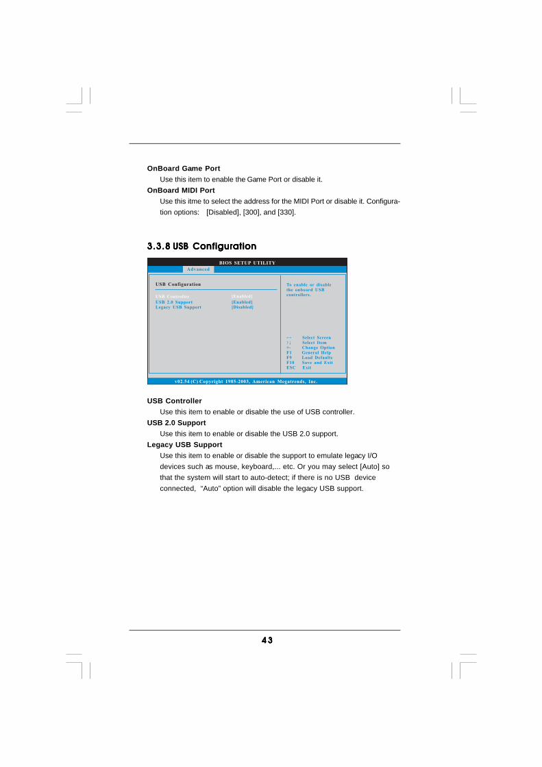
4 34 34 34 34 3
OnBoard Game PortUse this item to enable the Game Port or disable it.
OnBoard MIDI PortUse this itme to select the address for the MIDI Port or disable it. Configura-tion options: [Disabled], [300], and [330].
3.3.83.3.83.3.83.3.83.3.8 USB ConfigurationUSB ConfigurationUSB ConfigurationUSB ConfigurationUSB Configuration
USB ControllerUse this item to enable or disable the use of USB controller.
USB 2.0 SupportUse this item to enable or disable the USB 2.0 support.
Legacy USB SupportUse this item to enable or disable the support to emulate legacy I/Odevices such as mouse, keyboard,... etc. Or you may select [Auto] sothat the system will start to auto-detect; if there is no USB deviceconnected, “Auto” option will disable the legacy USB support.
BIOS SETUP UTILITY
USB Configuration To enable or disablethe onboard USBcontrollers.
Select ScreenSelect Item
+- Change OptionF1 General HelpF9 Load DefaultsF10 Save and ExitESC Exit
v02.54 (C) Copyright 1985-2003, American Megatrends, Inc.
Advanced
USB Controller
USB 2.0 SupportLegacy USB Support
[Enabled]
[Enabled][Disabled]
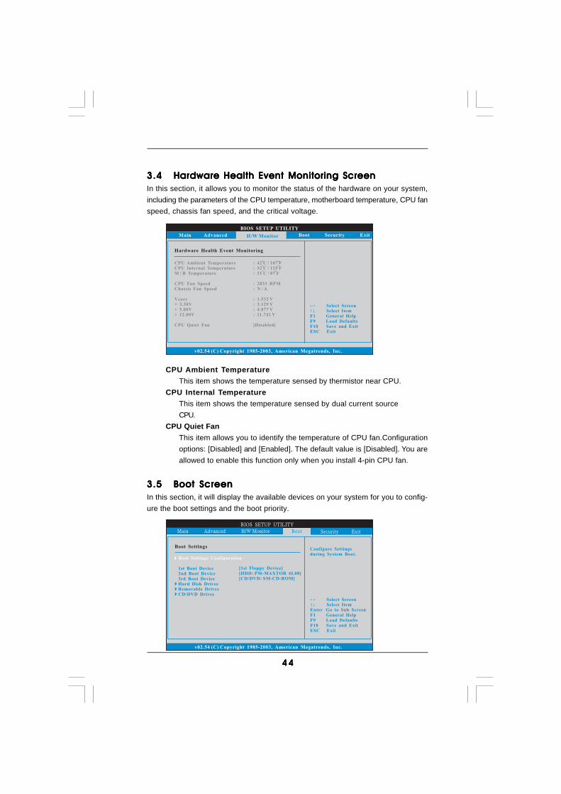
4 44 44 44 44 4
3.43.43.43.43.4 Hardware Health Event Monitoring ScreenHardware Health Event Monitoring ScreenHardware Health Event Monitoring ScreenHardware Health Event Monitoring ScreenHardware Health Event Monitoring ScreenIn this section, it allows you to monitor the status of the hardware on your system,including the parameters of the CPU temperature, motherboard temperature, CPU fanspeed, chassis fan speed, and the critical voltage.
CPU Ambient TemperatureThis item shows the temperature sensed by thermistor near CPU.
CPU Internal TemperatureThis item shows the temperature sensed by dual current sourceCPU.
CPU Quiet FanThis item allows you to identify the temperature of CPU fan.Configurationoptions: [Disabled] and [Enabled]. The default value is [Disabled]. You areallowed to enable this function only when you install 4-pin CPU fan.
3.53.53.53.53.5 Boot ScreenBoot ScreenBoot ScreenBoot ScreenBoot ScreenIn this section, it will display the available devices on your system for you to config-ure the boot settings and the boot priority.
BIOS SETUP UTILITY
Hardware Health Event Monitoring
Select ScreenSelect Item
F1 General HelpF9 Load DefaultsF10 Save and ExitESC Exit
v02.54 (C) Copyright 1985-2003, American Megatrends, Inc.
CPU Ambient TemperatureCPU Internal TemperatureM / B Temperature
CPU Fan SpeedChassis Fan Speed
Vcore+ 3.30V+ 5.00V+ 12.00V
CPU Quiet Fan
: 42 C / 107 F
: 2833 RPM: N / A
: 1.532 V: 3.129 V: 4.877 V: 11.741 V
[Disabled]
: 31 C / 87 F: 52 C / 125 F
Main Advanced Boot Security ExitH/W Monitor
BIOS SETUP UTILITY
Main Advanced H/W Monitor Security Exit
Boot SettingsConfigure Settingsduring System Boot.
Select ScreenSelect Item
Enter Go to Sub ScreenF1 General HelpF9 Load DefaultsF10 Save and ExitESC Exit
v02.54 (C) Copyright 1985-2003, American Megatrends, Inc.
Boot
Boot Settings Configuration
1st Boot Device2nd
Removable DrivesCD/DVD Drives
Boot Device3rd Boot DeviceHard Disk Drives
[1st Floppy Device][HDD: PM-MAXTOR 6L08][CD/DVD: SM-CD-ROM]
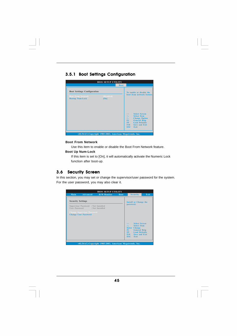
4 54 54 54 54 5
3.5.13.5.13.5.13.5.13.5.1 Boot Settings ConfigurationBoot Settings ConfigurationBoot Settings ConfigurationBoot Settings ConfigurationBoot Settings Configuration
Boot From NetworkUse this item to enable or disable the Boot From Network feature.
Boot Up Num-LockIf this item is set to [On], it will automatically activate the Numeric Lockfunction after boot-up.
BIOS SETUP UTILITY
Boot Settings ConfigurationTo enable or disable theboot from network feature.
Select ScreenSelect Item
+ - Change OptionF1 General HelpF9 Load DefaultsF10 Save and ExitESC Exit
v02.54 (C) Copyright 1985-2003, American Megatrends, Inc.
Boot
Boot From NetworkBootup Num-Lock
[Disabled][On]
3.63.63.63.63.6 Security ScreenSecurity ScreenSecurity ScreenSecurity ScreenSecurity ScreenIn this section, you may set or change the supervisor/user password for the system.For the user password, you may also clear it.
BIOS SETUP UTILITY
Main Advanced H/W Monitor Boot Exit
Install or Change thepassword.
Select ScreenSelect Item
Enter ChangeF1 General Help
F10 Save and ExitESC Exit
F9 Load Defaults
v02.54 (C) Copyright 1985-2003, American Megatrends, Inc.
Security
Change Supervisor Password
Change User Password
Security Settings
Supervisor Password : Not InstalledUser Password : Not Installed
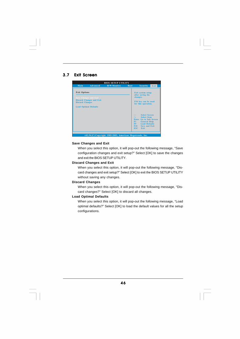
4 64 64 64 64 6
BIOS SETUP UTILITY
Main Advanced H/W Monitro Boot Security
Exit system setupafter saving thechanges.
F10 key can be usedfor this operation.
Select ScreenSelect Item
Enter Go to Sub ScreenF1 General Help
F10 Save and ExitESC Exit
F9 Load Defaults
v02.54 (C) Copyright 1985-2003, American Megatrends, Inc.
Exit
Save Changes and Exit
Discard Changes and ExitDiscard Changes
Load Optimal Defaults
Exit Options
3.73.73.73.73.7 Exit ScreenExit ScreenExit ScreenExit ScreenExit Screen
Save Changes and ExitWhen you select this option, it will pop-out the following message, “Saveconfiguration changes and exit setup?” Select [OK] to save the changesand exit the BIOS SETUP UTILITY.
Discard Changes and ExitWhen you select this option, it will pop-out the following message, “Dis-card changes and exit setup?” Select [OK] to exit the BIOS SETUP UTILITYwithout saving any changes.
Discard ChangesWhen you select this option, it will pop-out the following message, “Dis-card changes?” Select [OK] to discard all changes.
Load Optimal DefaultsWhen you select this option, it will pop-out the following message, “Loadoptimal defaults?” Select [OK] to load the default values for all the setupconfigurations.
4 74 74 74 74 7
4.4.4.4.4. Software SupporSoftware SupporSoftware SupporSoftware SupporSoftware Supporttttt4.1 Install Operating System4.1 Install Operating System4.1 Install Operating System4.1 Install Operating System4.1 Install Operating SystemThis motherboard supports various Microsoft® Windows® operating systems:2000 / XP / XP Media Center / XP 64-bit / VistaTM / VistaTM 64-bit. Because motherboardsettings and hardware options vary, use the setup procedures in this chapter forgeneral reference only. Refer to your OS documentation for more information.
4.2 Support CD Information4.2 Support CD Information4.2 Support CD Information4.2 Support CD Information4.2 Support CD InformationThe Support CD that came with the motherboard contains necessary drivers anduseful utilities that enhance the motherboard features.
4.2.1 Running The Support CD4.2.1 Running The Support CD4.2.1 Running The Support CD4.2.1 Running The Support CD4.2.1 Running The Support CDTo begin using the support CD, insert the CD into your CD-ROM drive. The CDautomatically displays the Main Menu if “AUTORUN” is enabled in your computer.If the Main Menu did not appear automatically, locate and double click on the file“ASSETUP.EXE” from the BIN folder in the Support CD to display the menus.
4.2.2 Drivers Menu4.2.2 Drivers Menu4.2.2 Drivers Menu4.2.2 Drivers Menu4.2.2 Drivers MenuThe Drivers Menu shows the available devices drivers if the system detects theinstalled devices. Please install the necessary drivers to activate the devices.
4.2.3 Utilities Menu4.2.3 Utilities Menu4.2.3 Utilities Menu4.2.3 Utilities Menu4.2.3 Utilities MenuThe Utilities Menu shows the applications software that the motherboard supports.Click on a specific item then follow the installation wizard to install it.
4.2.44.2.44.2.44.2.44.2.4 Contact InformationContact InformationContact InformationContact InformationContact InformationIf you need to contact ASRock or want to know more about ASRock, welcometo visit ASRock’s website at http://www.asrock.com; or you may contact yourdealer for further information.