Embed Size (px)
Citation preview

ATTACHMENT IIIPAGE 1 OF 55
SAFETY RECALL 13S12-S2
CPR © 2014 FORD MOTOR COMPANYDEARBORN, MICHIGAN 481214/2014
ALL 2013 MODEL YEAR ESCAPE VEHICLES EQUIPPED WITH A 1.6L ENGINE — RISK OF OVERHEATING THAT MAY RESULT IN ENGINE FIRES
OVERVIEW Safety Recall 13S12 applies to 2013 Model Year Escape models equipped with a 1.6L engine due to potential localized overheating of the engine cylinder head. The localized overheating may cause the engine cylinder head to crack, causing an oil leak that may result in a fi re in the engine compartment.Repairs include enhancements to the engine shielding system, engine cooling system, and engine control systems. Additionally, some vehicles have been observed with an engine oil overfi ll condition that occurred during service when the oil capacity was not properly identifi ed. An improved dip stick and label will be added to facilitate proper maintenance and improve customer satisfaction.
Due to the complexity of this repair, the following has been done to make the repair procedure go as smoothly as possible: • Repair procedures have been divided alphabetically into 14 separate procedures. • Parts have been packaged into three kits. - Water bypass kit (-8522-) with parts required to repair one vehicle. Parts in the kit are further packaged in bags and labeled for the procedures that they are used. - Oil level indicator assembly (-6750-) (Dipstick and label kit). - Dealer kit containing: 12.5 mm (0.5 in) material hole punch (100-D702), Motorcraft® ZC-31B towelettes, PM-13-A rust preventative. These components are used for multiple vehicles.
• Each procedure includes: - Overview - List and photo of the parts required - List of unique tools needed - Service tips to help complete the repair
NOTE: Please read this procedure in its entirety, prior to performing repairs. Additionally a video is available to assist.
NOTE: The IDS must be updated to software level 89.04A or later to perform the FSA. If the IDS is not updated when the FSA is performed, it may result in various DTCs and drivability concerns. It is important that all steps of this FSA are performed in the order listed. This will ensure proper operation of the vehicle once completed.

ATTACHMENT IIIPAGE 2 OF 55
SAFETY RECALL 13S12-S2
CPR © 2014 FORD MOTOR COMPANYDEARBORN, MICHIGAN 481214/2014
SERVICE PROCEDURE
Procedure A - Initial Disassembly and Preparation for Inspection
OVERVIEW: This procedure details the components to be removed to enable initial vehicle inspection.
PARTS / SUPPLIES REQUIRED: None
UNIQUE TOOL REQUIREMENTS: None
SERVICE TIPS: Please note the following: • The Inspection / Check Sheet (Attachment IV) must be printed and started during "Procedure A". • The air cleaner, mass air fl ow sensor and air intake tube are removed as an assembly. • Cover the turbocharger inlet opening to prevent dropping any parts or debris into the turbocharger while the turbocharger inlet pipe is off.
1. Print a copy of the Inspection / Check Sheet (Attachment IV), to record vehicle information and inspection/repair information for the vehicle. The Inspection / Check Sheet is to be attached/fi led with the recall repair order following completion, it does not need to be provided to Ford at this time.
2. Fill out top of Inspection / Check Sheet including: - VIN - Technician ID - Repair Order Number - Repair Date - Vehicle Mileage - Vehicle Build Date - Open Recalls
3. Using OASIS, document vehicle build date on the Inspection / Check Sheet.
- Vehicles built on or before April 19, 2013 will require Procedure H - Thermostat Replacement. - Check OASIS for 13Y03 or other open FSA(s).
4. With the vehicle in NEUTRAL, position it on a hoist. For additional information, refer to Workshop Manual (WSM) Section 100-02.
5. Using IDS/scan tool, retrieve and record DTCs on the Inspection / Check Sheet. - Any DTCs recorded will be used later in this procedure.
6. Remove the engine appearance cover.
7. Remove the cowl panel. For additional information, refer to WSM Section 501-02.
CPR © 2014 FORD MOTOR COMPANYDEARBORN, MICHIGAN 481214/2014
ATTACHMENT IVINSPECTION / CHECK SHEET
SAFETY RECALL 13S12-S2
Vehicle Identifi cation Number (VIN)
Repair Order#: Technician ID:
INSTRUCTIONS: Complete this Inspection / Check Sheet and attach / fi le it with the recall repair order following completion.
1. Record any DTCs present. Check appropriate box.
Pass - No DTCs present. Fail - DTCs present.
If fail, document any DTCs retrieved below, and reference during "Procedure B".
2. Visually inspect the coolant level in the degas bottle. Check appropriate box.
Pass - Coolant level is visible in the degas bottle. Fail - Coolant level is not visible in the degas bottle, needed to add coolant.
If fail, document any repairs performed below.
3. Pressure test cooling system. Check appropriate box.
Pass - Cooling system holds pressure for 2 minutes. Fail - Cooling system does not hold pressure for 2 minutes.
If fail, document any repairs performed below.
4. Visually check for coolant leaks with the system under pressure. Check appropriate box.
Pass - No coolant leak(s) found. Fail - Coolant leak(s) found.
If fail, document any repairs performed below.
5. Visually inspect the engine oil level and check for engine oil leaks at the rear surface of cylinder head, above exhaust manifold. Check appropriate box.
Pass - No engine oil leak(s) found. Fail - Engine oil leak(s) found.
If fail, document any repairs performed below.
13S12 VEHICLE INSPECTION / CHECK SHEET
Vehicle Mileage: Repair Date:
Vehicle Build Date: Open FSA(s):
Pass - Correct oil level. Fail - Engine oil not at correct level.

ATTACHMENT IIIPAGE 3 OF 55
SAFETY RECALL 13S12-S2
CPR © 2014 FORD MOTOR COMPANYDEARBORN, MICHIGAN 481214/2014
FIGURE A1
1235C
EVAP LINE QUICK CONNECT
COUPLING
CLAMP
AIR INTAKE TUBE
TURBOCHARGERINLET PIPE
All Vehicles
NOTICE: When working with liquid or vapor tube connectors, make sure to use compressed air to remove any foreign material from the connector retaining clip area before separating from the tube or damage to the tube or connector retaining clip can occur. Apply clean engine oil to the end of the tube before inserting the tube into the connector. NOTICE: Whenever turbocharger air intake system components are removed, always cover open ports to protect from debris. It is important that no foreign material enter the system. The turbocharger compressor vanes are susceptible to damage from even small particles. All components should be inspected and cleaned, if necessary, prior to installation or reassembly. 8. Disconnect the EVAP line quick connect coupling from the air intake tube center section. Set the clip aside for re-installation to prevent it from falling into the engine compartment. See Figure A1.
9. Loosen the clamp and disconnect the air intake tube from the turbocharger inlet pipe. See Figure A1.

ATTACHMENT IIIPAGE 4 OF 55
SAFETY RECALL 13S12-S2
CPR © 2014 FORD MOTOR COMPANYDEARBORN, MICHIGAN 481214/2014
11. Remove the battery tray. For additional information, refer to WSM Section 414-01.
• The air cleaner assembly was removed previously.
NOTE: The air cleaner assembly is removed from the vehicle with the mass air fl ow sensor and air intake tube attached.
10. Remove the air cleaner assembly. See Figure A2.
a. Disconnect the mass air fl ow sensor electrical connector. b. Release the fresh air intake tube fl ap. c. Detach the mass air fl ow sensor wire harness retainer from the air cleaner assembly. d. Lift upward to disengage the two retaining grommets and remove the air cleaner assembly.
FIGURE A21357E
WIRE HARNESSRETAINER
MASS AIR FLOWSENSOR ELECTRICAL
CONNECTOR
AIR CLEANERASSEMBLY
AIR INTAKE TUBE FLAP

ATTACHMENT IIIPAGE 5 OF 55
SAFETY RECALL 13S12-S2
CPR © 2014 FORD MOTOR COMPANYDEARBORN, MICHIGAN 481214/2014
NOTICE: Whenever turbocharger air intake system components are removed, always cover open ports to protect from debris. It is important that no foreign material enter the system. The turbocharger compressor vanes are susceptible to damage from even small particles. All components should be inspected and cleaned, if necessary, prior to installation or reassembly.
12. Disconnect the PCV tube from the turbocharger inlet pipe. Remove the retainers and loosen the clamp at the turbocharger. Remove the turbocharger inlet pipe. See Figure A3.
FIGURE A3
1238B
PCV TUBE
TURBOCHARGERINLET PIPE
CLAMP
RETAINERS
13. Remove the retainers and the front underbody air defl ector. See Figure A4.
1312A
x7
x2
UNDERBODY AIRDEFLECTOR
FIGURE A4

ATTACHMENT IIIPAGE 6 OF 55
SAFETY RECALL 13S12-S2
CPR © 2014 FORD MOTOR COMPANYDEARBORN, MICHIGAN 481214/2014
Procedure B - Inspection / Check Sheet Completion
OVERVIEW: The Inspection must be completed and documented on the Inspection / Check Sheet. The inspection will check for obvious issues that require correction with additional focus on cooling system issues such as: • Coolant loss • External coolant leaks • Any DTC(s) that could indicate overheat or are a result of internal engine damage that resulted from a previous cooling system failure.
PARTS / SUPPLIES REQUIRED: None
UNIQUE TOOL REQUIREMENTS: Rotunda Cooling System Pressure Tester (STN12270) and a commercially available adapter (Snap-On TA52, AST ASSFZ-47, Redline RDL95-0750 or equivalent).
SERVICE TIPS: Use standard Workshop Manual and PC/ED Diagnostics, if necessary, to diagnose any cooling system or misfi re DTC(s) retrieved and for any unexplained loss of coolant issues.
NOTE: Perform a quick underhood visual inspection for any obvious coolant, oil, transmission, or fuel leaks.
NOTE: Repair any issues identifi ed as related damage before proceeding. If the coolant pressure test identifi es issues with the degas bottle, turbocharger return tube, upper section of the degas bottle return hose, or quick connect T-fi tting at the coolant shutoff solenoid valve; note the condition. These items will be replaced as part of this recall. Refer to Dealer Bulletin Attachment I, Related Damage, for related damage claiming.
Vehicle Inspection
1. Visually inspect the coolant level in the degas bottle. • If the coolant level is visible in the degas bottle, proceed to Step 2. • If the coolant level is not visible in the degas bottle, add coolant as necessary, and proceed to Step 2.
NOTE: Any gross loss of coolant must be identifi ed and repaired prior to proceeding.
2. Remove the degas bottle cap.
3. Install a coolant pressure tester with adapter onto the degas bottle. Pressurize to 138 kPa (20 psi). Once stabilized, pressure should hold at 138 kPa (20 psi) for a minimum of 2 minutes. - If pressure test fails, the source of pressure loss must be identifi ed and repaired as necessary before proceeding.
4. Visually check for coolant leaks with the system under pressure. 5. Check the engine oil level to ensure it is within normal range, note if it is overfi lled. Visually check for engine oil leaks at the rear surface of cylinder head, above exhaust manifold, that may be the result of a crack in the cylinder head.
ATTACHMENT IIIPAGE 7 OF 55
SAFETY RECALL 13S12-S2
CPR © 2014 FORD MOTOR COMPANYDEARBORN, MICHIGAN 481214/2014
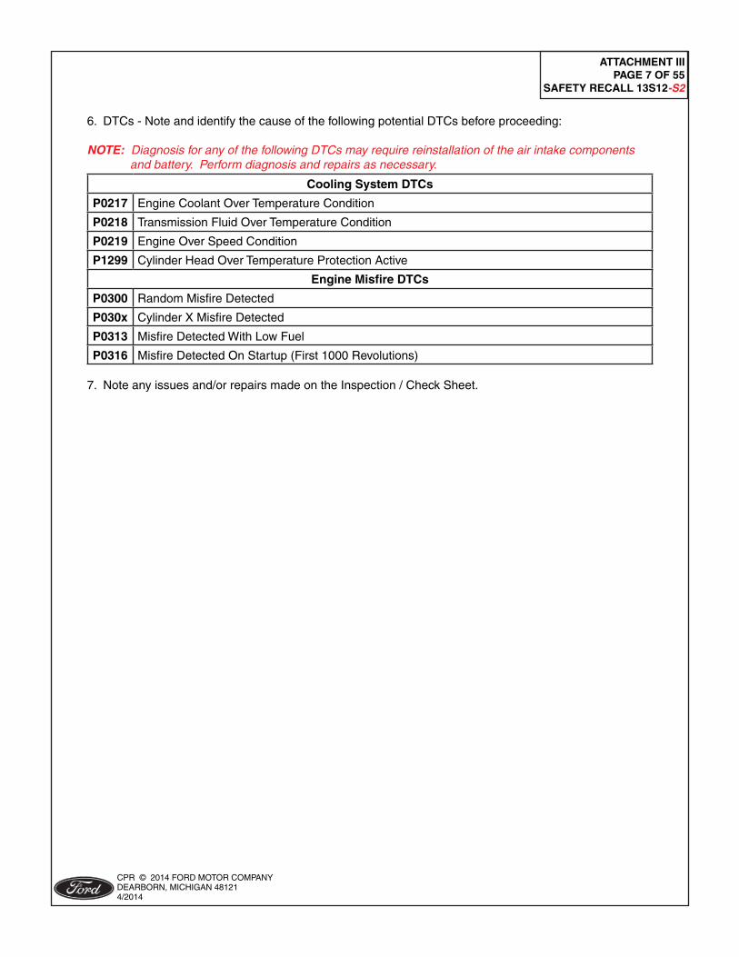
6. DTCs - Note and identify the cause of the following potential DTCs before proceeding:
NOTE: Diagnosis for any of the following DTCs may require reinstallation of the air intake components and battery. Perform diagnosis and repairs as necessary.
Cooling System DTCs
P0217 Engine Coolant Over Temperature Condition
P0218 Transmission Fluid Over Temperature Condition
P0219 Engine Over Speed Condition
P1299 Cylinder Head Over Temperature Protection Active
Engine Misfi re DTCs
P0300 Random Misfi re Detected
P030x Cylinder X Misfi re Detected
P0313 Misfi re Detected With Low Fuel
P0316 Misfi re Detected On Startup (First 1000 Revolutions) 7. Note any issues and/or repairs made on the Inspection / Check Sheet.

ATTACHMENT IIIPAGE 8 OF 55
SAFETY RECALL 13S12-S2
CPR © 2014 FORD MOTOR COMPANYDEARBORN, MICHIGAN 481214/2014
Procedure C - Cast Engine Shield Installation
OVERVIEW: The new cast engine shield is installed on the back of the cylinder head to defl ect an oil leak caused by engine overheating.
PARTS / SUPPLIES REQUIRED:
1357RR
G
A
D EB
F
C
A Cast Engine Shield Assembly
B Cast Engine Shield Mounting Bolts (2 ea.)
C LOCTITE® #5920 Copper RTV Silicone
D Heat Shield Attaching Bolts (2 ea.)
E Heat Shield Stud
F Heat Shield Stud Nut (1 ea.)
G Turbocharger Coolant Inlet/Outlet Banjo Fitting Copper Washers (2 ea. Flat, 2 ea. Rolled)
H Motorcraft® ZC-31B Towelette (1 ea.) (Supplied in Dealer Kit) (Not Shown)
I Motorcraft® Metal Brake Parts Cleaner (PM-4-A or PM-4-B)(Dealer Procured) (Not Shown)
UNIQUE TOOL REQUIREMENTS: None
SERVICE TIPS: Follow all installation steps and torque sequences in this procedure in the order provided to ensure the new cast engine shield and the exhaust manifold heat shield align properly for fastener installation.

ATTACHMENT IIIPAGE 9 OF 55
SAFETY RECALL 13S12-S2
CPR © 2014 FORD MOTOR COMPANYDEARBORN, MICHIGAN 481214/2014
FIGURE C1
1357C
TURBOCHARGERCOOLANT RETURN
TUBE
CLAMP
CLIP
DEGAS BOTTLECONNECTION
NOTE: On some vehicles, the coolant may have a green appearance, especially on a black background. This is a normal condition due to the addition of a dye during vehicle assembly. Motorcraft® orange antifreeze/coolant is used in all 2013 Escape applications.
1. Drain the cooling system. For additional information, refer to WSM Section 303-03A.
2. Remove and discard the turbocharger coolant return tube. See Figure C1.
a. Disconnect the turbocharger coolant return tube from the degas bottle. b. Detach the clip from the coolant return tube. c. Release the clamp, remove and discard the coolant return tube.
FIGURE C2
1357F
INLET TUBEBRACKET
BOLT
TURBOCHARGERCOOLANT INLET
TUBE
TURBOCHARGERCOOLANT OUTLET
TUBE
OUTLET TUBEBRACKET
BOLT
NOTE: Once the turbocharger coolant inlet and outlet tubes are removed, ensure that the banjo bolt copper washers do not remain on the turbocharger.
3. Remove the turbocharger coolant inlet and outlet tube bracket bolts. See Figure C2.
• Discard the turbocharger outlet tube bolt. • The inlet tube bracket bolt will be reused during reassembly.

ATTACHMENT IIIPAGE 10 OF 55
SAFETY RECALL 13S12-S2
CPR © 2014 FORD MOTOR COMPANYDEARBORN, MICHIGAN 481214/2014
NOTICE: Be careful to not touch or damage the surface of the banjo fi ttings while removing the copper washers from the banjo bolts.
4. Remove the banjo bolts and the turbocharger coolant outlet tube. Position aside the turbocharger coolant inlet tube. See Figure C3. • Discard both copper washers after removal. • If required, use a pair of needle nose pliers to hold the copper washers while turning the banjo bolt to thread the washer off of the bolt.
FIGURE C3
1357F
TURBOCHARGERCOOLANT INLET
TUBE
BANJOBOLTS
TURBOCHARGERCOOLANT OUTLET
TUBE
5. Remove the four (4) bolts and the exhaust manifold heat shield. See Figure C4.
• Do not discard the bottom heat shield bolt. It will be reused during assembly.
FIGURE C4
1357BK
EXHAUST MANIFOLDHEAT SHIELD

ATTACHMENT IIIPAGE 11 OF 55
SAFETY RECALL 13S12-S2
CPR © 2014 FORD MOTOR COMPANYDEARBORN, MICHIGAN 481214/2014
6. Prepare the cylinder head for the new cast engine shield installation. See Figure C5.
a. Spray and wipe down the rear of the cylinder head using Motorcraft® Metal Brake Parts Cleaner (PM-4-A or PM-4-B). • Repeat this step a second time and ensure the surface is oil free. • Blow dry using compressed air to remove any puddles. b. Using one (1) towelette from the Motorcraft® ZC-31B (Bonderite 1455) canister, wipe the rear of the cylinder head in the area shown. This etches the aluminum to allow proper bond with the LOCTITE® 5920 copper RTV silicone.
FIGURE C5
1357O
REAR OFCYLINDER HEAD
NOTICE: Ensure that the new cast engine shield stays clean and free from any dirt or vehicle fl uids. Any contamination may result in failure of the new engine oil shield to seal to the engine.

ATTACHMENT IIIPAGE 12 OF 55
SAFETY RECALL 13S12-S2
CPR © 2014 FORD MOTOR COMPANYDEARBORN, MICHIGAN 481214/2014
FIGURE C7
1357Q
NEW DRIVER’S SIDE BOLT
NEW CAST ENGINE SHIELD
NOTE: Moisture curing begins immediately after the product is exposed to the atmosphere, therefore parts to be assembled should be mated within a few minutes after the product is dispensed. After the product is applied "Procedure C" should be completed within 20 minutes.
7. Apply two (2) 3 mm to 5 mm beads of LOCTITE® 5920 copper RTV silicone (approximately 1/2 tube) that is supplied in the vehicle parts kit to the new cast engine shield. See Figure C6.
FIGURE C6
1357P
LOCTITE® 5920COPPER RTV
SILICONE
NEW CAST ENGINE SHIELD
8. Carefully position the new cast engine shield to the rear of the cylinder head and install the new driver's side bolt fi nger tight. The LOCTITE® patch on the bolt will only allow you to install it a few threads. See Figure C7. • Do not fully tighten the bolt at this time.

ATTACHMENT IIIPAGE 13 OF 55
SAFETY RECALL 13S12-S2
CPR © 2014 FORD MOTOR COMPANYDEARBORN, MICHIGAN 481214/2014
9. Install the new heat shield stud at the upper driver's side exhaust manifold heat shield bolt location. See Figure C8. • Tighten to 10 Nm (89 lb-in).
NOTE: Ensure the new heat shield stud is installed onto the exhaust manifold as shown. Do not install onto the engine. See Figure C8.
10. While holding the heat shield in position, loosely install the previously removed exhaust heat shield bottom bolt. Do not attempt to secure the upper portion of the heat shield into place until the bottom bolt is started into the threads on the turbocharger housing boss. See Figure C9.
FIGURE C8
1357CCC
NEW HEATSHIELD STUD
EXHAUSTMANIFOLD
DO NOT INSTALLNEW HEAT SHIELDSTUD ON ENGINE
FIGURE C9
1357S
PREVIOUSLY REMOVED EXHAUSTHEAT SHIELD BOTTOM BOLT
EXHAUST MANIFOLDHEAT SHIELD

ATTACHMENT IIIPAGE 14 OF 55
SAFETY RECALL 13S12-S2
CPR © 2014 FORD MOTOR COMPANYDEARBORN, MICHIGAN 481214/2014
NOTE: When re-installing the exhaust manifold heat shield, fi rst install the bolt at the lower turbocharger boss loosely, then push down on the top of the heat shield to fi t it over the stud installed at the upper left side, then pull it toward the front of the vehicle tight up under the lip of the cast engine shield. Use an inspection mirror to identify any areas where the shield might get hung up on installation.
11. While pressing downward, position the exhaust heat shield onto the new heat shield stud and under the RH side of the new cast engine shield. See Figure C10.
12. Continue to press downward and pull forward to roll the exhaust manifold heat shield under the new cast engine shield. See Figure C11.
FIGURE C10
1357DDD
NEW CAST ENGINE SHIELD
NEW HEATSHIELD STUD
EXHAUST MANIFOLDHEAT SHIELD
FIGURE C11
1357BA
NEW CAST ENGINE SHIELD
NEW CAST ENGINE SHIELD
EXHAUST MANIFOLDHEAT SHIELD
EXHAUST MANIFOLDHEAT SHIELD

ATTACHMENT IIIPAGE 15 OF 55
SAFETY RECALL 13S12-S2
CPR © 2014 FORD MOTOR COMPANYDEARBORN, MICHIGAN 481214/2014
13. Install the two (2) new bolts and new heat shield stud nut onto the exhaust manifold heat shield. See Figure C12.
FIGURE C12
1357BC
EXHAUST MANIFOLDHEAT SHIELD
BOLTHEAT SHIELD
STUD NUT
14. Tighten the four (4) exhaust manifold heat shield retainers to 10 Nm (89 lb-in). See Figures C9 and C12.
NOTE: When reinstalling the turbocharger inlet and outlet coolant tubes, the new banjo bolt copper washers must be installed as follows: See Figure C13. • The rolled compression copper washer should be installed between the turbocharger inlet and outlet coolant tubes and the turbocharger. • The fl at copper washer should be installed between the banjo bolt head and the turbocharger inlet and outlet coolant tubes.
FIGURE C13
1357R
TURBOCHARGERCOOLANT TUBE
FLAT COPPERWASHER
ROLLED COMPRESSIONCOPPER WASHER
BANJOBOLT

ATTACHMENT IIIPAGE 16 OF 55
SAFETY RECALL 13S12-S2
CPR © 2014 FORD MOTOR COMPANYDEARBORN, MICHIGAN 481214/2014
15. Install the vehicle parts kit supplied banjo bolt copper washers and the banjo bolts onto the turbocharger coolant inlet and outlet tubes. See Figure C13. 16. Loosely install the turbocharger coolant inlet and outlet tubes and banjo bolts onto the turbocharger. See Figure C3.
17. Loosely install the coolant inlet tube bracket bolt. See Figure C2. 18. Loosely install the remaining new cast engine shield bolt. This bolt also will retain the turbocharger coolant outlet tube bracket. See Figure C14. 19. Tighten the turbocharger coolant inlet and outlet tube banjo bolts to 28 Nm (21 lb-ft). See Figure C3.
20. Tighten both new cast engine shield bolts to 28 Nm (21 lb-ft). See Figure C14.
FIGURE C14
1357BD
EXHAUST MANIFOLDHEAT SHIELD
TURBOCHARGERCOOLANT OUTLET
TUBE
NEW CAST ENGINE SHIELD
NEW CAST ENGINESHIELD BOLTS
21. Tighten the coolant inlet tube bracket bolt to 23 Nm (17 lb-ft). See Figure C2.

ATTACHMENT IIIPAGE 17 OF 55
SAFETY RECALL 13S12-S2
CPR © 2014 FORD MOTOR COMPANYDEARBORN, MICHIGAN 481214/2014
Procedure D - Battery Tray Modifi cation
OVERVIEW: The battery tray is removed and four holes are drilled in the right side to allow mounting of wiring harness components that will be added to support coolant level monitoring. The battery is reinstalled to allow Instrument Panel Cluster (IPC) programming, while additional repairs are performed.
PARTS / SUPPLIES REQUIRED:
1357SS
A
C B
A Connector Junction Box
B Push Pin Retainers (2 ea.)
C Wiring Harness Clip
UNIQUE TOOL REQUIREMENTS: 5.5 mm (7/32" / 0.21 in), 6.3 mm (1/4" / 0.25 in) drill bits.
SERVICE TIPS: Remove the two (2) push pin retainers from the connector junction box, prior to installation. While installing the connector junction box ensure that the push pin retainers are installed in the proper orientation. See Figure D4.

ATTACHMENT IIIPAGE 18 OF 55
SAFETY RECALL 13S12-S2
CPR © 2014 FORD MOTOR COMPANYDEARBORN, MICHIGAN 481214/2014
FIGURE D1
1357BE
BATTERY TRAY10MM (0.39IN) DOWN
FROM TOP EDGE
NEW CONNECTORJUNCTION BOX
DRILL 6.3 MM(1/4" / 0.25 IN)
FRONT
DRILL 6.3 MM(1/4" / 0.25 IN)
1. Using the dimensions shown below, mark and drill the locations of the two (2) holes that are required for the new connector junction box, in the right side of the battery tray. See Figure D1.
a. Position the new connector junction box on the forward right side of the battery tray, 10mm (0.39 in) down from the top edge of the battery tray. Using the new connector junction box as a template, mark the two (2) hole locations on the battery tray. See Figure D1. b. Remove the new connector junction box from the battery tray. c. Using a 6.3 mm (1/4" / 0.25 in) drill bit, drill the two marked locations on the battery tray.
2. Measure and mark the two hole locations on the battery tray for the new wire harness clip. See Figure D2.
FIGURE D2
1357T
BATTERY TRAY
10MM (0.39IN)
20MM (0.79IN)
32MM (1.26IN)
FRONT

ATTACHMENT IIIPAGE 19 OF 55
SAFETY RECALL 13S12-S2
CPR © 2014 FORD MOTOR COMPANYDEARBORN, MICHIGAN 481214/2014
4. Deburr the four (4) previously drilled holes on the battery tray as necessary.
5. Attach the new connector junction box to the battery tray using the two (2) new push pin retainers. Install the new push pin retainers so the heads of the retainers are on the inside of the battery tray. See Figure D4.
6. Install the new wire harness clip onto the battery tray. The christmas tree portion of the new wire harness clip is to be installed into the larger of the two mounting holes. See Figure D4.
3. Using the appropriate size drill bit for two (2) remaining marked locations on the battery tray, 5.5 mm (7/32" / 0.21 in) and 6.3 mm (1/4" / 0.25) as indicated in Figure D3, drill the two (2) holes. See Figure D3.
FIGURE D31357BF
BATTERY TRAY
DRILL 5.5 MM(7/32" / 0.21 IN)
FRONT
DRILL 6.3 MM(1/4" / 0.25 IN)
FIGURE D4
1357U
NEW CONNECTORJUNCTION BOX
NEW WIRE HARNESS CLIP
NEWPUSH PIN
RETAINERS

ATTACHMENT IIIPAGE 20 OF 55
SAFETY RECALL 13S12-S2
CPR © 2014 FORD MOTOR COMPANYDEARBORN, MICHIGAN 481214/2014
FIGURE D6
1357H
BATTERY B+TERMINAL CABLE
7. Position the battery tray back into the vehicle and install the three (3) bolts. See Figure D5.
• Tighten to 11 Nm (97 lb-in).
Vehicles built on or before April 19, 2013
8. Install and connect the battery. For additional information, refer to WSM Section 414-01. • Do not connect the battery cable to ground at this time. • Do not reinstall the engine air cleaner assembly at this time. It will be installed in one of the following procedures. • Do not attach the transmission fl uid heater coolant control valve to the battery tray at this time. See Figure E5.
9. Remove the nut and disconnect the battery B+ terminal cable. See Figure D6.
FIGURE D5
1357GBATTERY
TRAY
x3
10. Connect the battery cable to ground. For additional information, refer to WSM Section 414-01.

ATTACHMENT IIIPAGE 21 OF 55
SAFETY RECALL 13S12-S2
CPR © 2014 FORD MOTOR COMPANYDEARBORN, MICHIGAN 481214/2014
Vehicles built on or after April 20, 2013
11. Install and connect the battery. For additional information, refer to WSM Section 414-01.

ATTACHMENT IIIPAGE 22 OF 55
SAFETY RECALL 13S12-S2
CPR © 2014 FORD MOTOR COMPANYDEARBORN, MICHIGAN 481214/2014
Procedure E - Coolant Stand-pipe Wire Harness Installation
OVERVIEW: The coolant stand-pipe wire harness is partially installed in this procedure. This is necessary to complete the connections at the 6-pin EPAS electrical connectors which are a part of the CAN Network. The CAN Network must be complete to allow module programming.
PARTS / SUPPLIES REQUIRED:
1357TT
A
C
B
A Coolant Stand-pipe Wire Harness
B Wire Harness Ground Bolt
C Protective Foam Pad
UNIQUE TOOL REQUIREMENTS: None
SERVICE TIPS: None

ATTACHMENT IIIPAGE 23 OF 55
SAFETY RECALL 13S12-S2
CPR © 2014 FORD MOTOR COMPANYDEARBORN, MICHIGAN 481214/2014
FIGURE E1
1357V
6-PIN EPAS ELECTRICALCONNECTOR
BATTERY TRAYMOUNTING BRACKET
RETAINING CLIP
2. Connect the new coolant stand-pipe wire harness electrical connector to the new connector junction box. Apply the foam pad over the new connector junction box and electrical connector. See Figure E2.
NOTE: The new coolant stand-pipe wire harness is highlighted to show routing and connection points.
FIGURE E2
1357W
NEW CONNECTORJUNCTION BOX
FOAM PAD
NEW CONNECTORJUNCTION BOXNEW COOLANT
STAND-PIPE WIREHARNESS ELECTRICAL
CONNECTOR
1. Detach the retaining clip from the battery tray mounting bracket. Disconnect the 6-pin EPAS electrical connectors. See Figure E1.
• Remove and discard the retaining clip from the 6-pin EPAS electrical connector.

ATTACHMENT IIIPAGE 24 OF 55
SAFETY RECALL 13S12-S2
CPR © 2014 FORD MOTOR COMPANYDEARBORN, MICHIGAN 481214/2014
FIGURE E3
1357X
FEMALE END OF NEW COOLANT STAND-PIPEWIRE HARNESS CONNECTED TO 6-PIN
EPAS ELECTRICAL CONNECTOR
MALE END OF NEW COOLANT STAND-PIPEWIRE HARNESS CONNECTED TO 6-PIN
EPAS ELECTRICAL CONNECTOR
3. Connect the new coolant stand-pipe wire harness 6-pin electrical connectors to the 6-pin EPAS electrical connectors. See Figure E3.
4. Attach the electrical connectors (female end of coolant stand-pipe / male end of 6-pin EPAS electrical connectors) to the white retaining clip that was previously installed on the battery tray. See Figure E3.
5. Attach the electrical connectors (male end of coolant stand-pipe / female end of 6-pin EPAS electrical connectors) to the battery tray mounting bracket. See Figure E3.

ATTACHMENT IIIPAGE 25 OF 55
SAFETY RECALL 13S12-S2
CPR © 2014 FORD MOTOR COMPANYDEARBORN, MICHIGAN 481214/2014
FIGURE E4
1357Y
NEW COOLANTSTAND-PIPE WIRE
HARNESS GROUNDEYELET
6. Install the new coolant stand-pipe wire harness ground eyelet to the vehicle using the new wire harness ground bolt. See Figure E4.
• Tighten to 12 Nm (106 lb-in).
7. Position the stand-pipe wire harness aside. It will be routed/secured and connected later.
8. Install the transmission fl uid heater coolant control valve to the battery tray and install the two (2) retainers. See Figure E5.
FIGURE E5
1357BJ
TRANSMISSION FLUIDHEATER COOLANTCONTROL VALVE
ATTACHMENT IIIPAGE 26 OF 55
SAFETY RECALL 13S12-S2
CPR © 2014 FORD MOTOR COMPANYDEARBORN, MICHIGAN 481214/2014
Procedure F - Instrument Panel Cluster (IPC) Reprogramming
OVERVIEW: The IPC software is being updated to coordinate cooling system improvements and instrument cluster messaging. IPC reprogramming can be done while other repairs are performed on the vehicle. The PCM must be reprogrammed during Procedure N after repairs and cooling system bleeding are completed.
PARTS / SUPPLIES REQUIRED: None
UNIQUE TOOL REQUIREMENTS: • IDS with release 89.04A or higher • Portable battery charger (10 to 20 amps)
SERVICE TIPS: Begin IPC reprogramming and continue to perform repairs while software loads. Programming times for this IPC can be signifi cantly reduced by using a VCM II instead of a VCM.
Important Information for Module Programming NOTE: When programming or reprogramming a module, use the following basic checks to ensure programming completes without errors.
• Make sure the 12V battery is fully charged before carrying out the programming steps and connect IDS/scan tool to a power source.
• Inspect Vehicle Communication Module (VCM) and cables for any damage. Make sure scan tool connections are not interrupted during programming.
• A hardwired connection is strongly recommended.
• Turn off all unnecessary accessories (radio, heated/cooled seats, headlamps, interior lamps, HVAC system, etc.) and close doors.
• Disconnect/depower any aftermarket accessories (remote start, alarm, power inverter, CB radio, etc.).
• Follow all scan tool on-screen instructions carefully.
• Disable IDS/scan tool sleep mode, screensaver, hibernation modes. • Create all sessions Key On Engine Off (KOEO). Starting the vehicle before creating a session will cause errors within the programming inhale process.
Module Reprogramming NOTE: Reprogram appropriate vehicle modules before performing diagnostics and clear all Diagnostic Trouble Codes (DTCs) after programming. For DTCs generated after reprogramming, follow normal diagnostic service procedures.

ATTACHMENT IIIPAGE 27 OF 55
SAFETY RECALL 13S12-S2
CPR © 2014 FORD MOTOR COMPANYDEARBORN, MICHIGAN 481214/2014
NOTE: Current draw during reprogramming may be in excess of 10 amps. Use a battery charger set to between 10 to 20 amps. Also ensure the headlamps and accessories are turned off, in order maintain proper battery charge.
1. The IPC reprogramming can take up to 1 hour or more. Connect a portable battery charger of 10 to 20 amps to an extension cord and to the 12V battery. This will allow the vehicle to be raised and lowered as needed while completing the remaining repair procedures, and ensure uninterrupted reprogramming is achieved. Programming times can be signifi cantly reduced by using a VCMII.
NOTE: Periodically check the status of the reprogramming progress to continue the process, as required. 2. Reprogram the IPC using IDS release 89.04A or higher. NOTE: Calibration fi les may also be obtained at www.motorcraft.com.
NOTE: Follow the IDS on-screen instructions to complete the reprogramming procedure.
Recovering a module when programming has resulted in a blank module: NEVER DELETE THE ORIGINAL SESSION!
a. Obtain the original IDS that was used when the programming error occurred during Module Reprogramming (MR) or Programmable Module Installation (PMI).
b. Disconnect the VCM from the Data Link Connector (DLC) and the IDS.
c. Reconnect the VCM to IDS and then connect to the DLC. Once reconnected, the VCM icon should appear in the corner of the IDS screen. If it does not, troubleshoot the IDS to VCM connection.
d. Locate the ORIGINAL vehicle session when programming failed. This should be the last session used in most cases. If not, use the session created on the date that the programming failed.
NOTE: If the original session is not listed in the previous session list, click the ''Recycle Bin'' icon at the lower right of the previous session screen. This loads any deleted sessions and allows you to look through them. Double-click the session to restore it.
e. Once the session is loaded, the failed process should resume automatically.
f. If programming does not resume automatically, proceed to the Module Programming menu and select the previously attempted process, PMI or MR.
g. Follow all on-screen prompts/instructions.
h. The last screen on the IDS may list additional steps required to complete the programming process. Make sure all applicable steps listed on the screen are followed in order.

ATTACHMENT IIIPAGE 28 OF 55
SAFETY RECALL 13S12-S2
CPR © 2014 FORD MOTOR COMPANYDEARBORN, MICHIGAN 481214/2014
Procedure G - Turbocharger Wire Harness Taping
OVERVIEW: This procedure wraps the turbocharger wire harness with Coroplast® tape to prevent the entry/buildup of fl uids and debris in the convolute which could ignite from an ignition source.
PARTS / SUPPLIES REQUIRED:
1357UU
AB
A Coroplast® Tape
B Wire Harness Retainer w/Zip Tie
UNIQUE TOOL REQUIREMENTS: None
SERVICE TIPS: Tips for wrapping the harness are included in the procedure.

ATTACHMENT IIIPAGE 29 OF 55
SAFETY RECALL 13S12-S2
CPR © 2014 FORD MOTOR COMPANYDEARBORN, MICHIGAN 481214/2014
2. Route the turbocharger wire harness to the top of the engine compartment. See Figure G2.
FIGURE G2
1357Z
TURBOCHARGERWIRE HARNESS
1. Detach the wire harness retainer from the front cover, disconnect the crankshaft position sensor, turbocharger wastegate regulating valve solenoid, and turbocharger bypass valve electrical connectors. See Figure G1.
FIGURE G11357D
FRONT OFVEHICLE
TURBOCHARGERWASTEGATEREGULATING
VALVE SOLENOID
TURBOCHARGERBYPASS VALVE
CRANKSHAFT POSITIONSENSOR
WIRE HARNESSRETAINER
REAR VCT OILCONTROL SOLENOID

ATTACHMENT IIIPAGE 30 OF 55
SAFETY RECALL 13S12-S2
CPR © 2014 FORD MOTOR COMPANYDEARBORN, MICHIGAN 481214/2014
3. Disconnect the rear Variable Camshaft Timing (VCT) oil control solenoid. See Figure G1.
• Detach the VCT harness retaining clip from the turbocharger outlet tube.
4. Replace the wire harness retainer with a new one supplied in the vehicle parts kit. See Figure G3.
• Mark the wire harness retainer location before removal.
5. Wrap the turbocharger wire harness convolute with the Coroplast® tape provided in the service kit. See Figure G3.
• Start and fi nish each length of tape applied with three (3) initial and three (3) fi nishing wraps. • Apply each wrap of tape with a 50% overwrap.
• First, wrap the takeout for the crankshaft position sensor. Begin the wrap at the connector and end this portion of wrapping by going around the main harness at the takeout. See Figure G3, (A). • Wrap the turbocharger harness starting at the takeout to the rear VCT solenoid. Proceed down the remaining length of harness to the turbocharger wastegate regulating valve solenoid connector. See Figure G3, (B).
FIGURE G3
1357AA
TURBOCHARGERWIRE HARNESS
WIRE HARNESSRETAINER
CRANKSHAFT POSITIONSENSOR CONNECTOR TURBOCHARGER WASTEGATE
REGULATING VALVE SOLENOID CONNECTOR
A
B
6. Connect the rear VCT oil control solenoid. See Figure G1.
• Attach the VCT harness retaining clip to the turbocharger outlet tube.
7. Route the wire harness back down to the crankshaft position sensor, turbocharger wastegate regulating valve solenoid, and turbocharger bypass valve. See Figure G1.
8. Attach the wire harness retainer to the front cover. Connect the crankshaft position sensor, turbocharger wastegate regulating valve solenoid, and turbocharger bypass valve electrical connectors. See Figure G1.

ATTACHMENT IIIPAGE 31 OF 55
SAFETY RECALL 13S12-S2
CPR © 2014 FORD MOTOR COMPANYDEARBORN, MICHIGAN 481214/2014
Procedure H - Thermostat Replacement (Only Vehicles built on or before April 19, 2013)
OVERVIEW: Vehicles built on or before April 19, 2013 currently have a 90 deg. C thermostat. These are being replaced to use the cooler 82 deg. C thermostat as used in vehicles built after April 19, 2013 to improve cooling system performance.
PARTS / SUPPLIES REQUIRED:
1357VV
A
C
B
A Thermostat
B Thermostat housing to cylinder block O-rings (2 ea.)
C Thermostat Housing to coolant valve O-Ring (1 ea.)
UNIQUE TOOL REQUIREMENTS: None
SERVICE TIPS: Note that the thermostat is removed and installed with the thermostat housing positioned aside and the two hoses still attached to the thermostat housing. Make sure the air bleed in the thermostat is in the “UP” position when installed to allow any air trapped in the system to pass.

ATTACHMENT IIIPAGE 32 OF 55
SAFETY RECALL 13S12-S2
CPR © 2014 FORD MOTOR COMPANYDEARBORN, MICHIGAN 481214/2014
NOTE: "Procedure H" only applies to vehicles built on or before 4/19/2013. For vehicles built on or after 4/20/2013, proceed to "Procedure I".
NOTE: For vehicles built on or after 4/20/2013, the thermostat, thermostat gaskets, and coolant shutoff solenoid valve o-ring provided in the vehicle parts kit are not used.
1. Remove the coolant shutoff solenoid valve. For additional information, refer to WSM Section 303-03A.
• This procedure requires removal of the generator. For additional information, refer to WSM Section 414-02. • Do not disconnect the battery as referenced within generator removal and installation. The battery B+ terminal cable was disconnected during "Procedure D", to remove battery voltage from the generator cable during thermostat replacement.
2. Remove the four bolts and position the thermostat housing aside to access to the thermostat. See Figure H1.
• Discard the thermostat housing gaskets.
FIGURE H1
x4x41357BB
THERMOSTATHOUSING

ATTACHMENT IIIPAGE 33 OF 55
SAFETY RECALL 13S12-S2
CPR © 2014 FORD MOTOR COMPANYDEARBORN, MICHIGAN 481214/2014
FIGURE H3
1357DD
THERMOSTATHOUSING
THERMOSTATAIR BLEED
HOLE
4. Remove and discard the thermostat. See Figure H3.
5. Position the new thermostat into the housing with the air bleed hole positioned upward. Use a 13 mm (1/2 in) deep well socket to install the thermostat spring and clip. The retaining clip must be in the same orientation that it was in prior to removal. See Figures H3 and H4.
3. Use a 13 mm (1/2 in) deep well socket to press downward on the thermostat retaining clip and rotate to remove it from the thermostat housing. Remove the thermostat spring. See Figure H2.
• Note the position of the thermostat retaining clip and thermostat prior to removing. See Figures H2 and H4.
FIGURE H21357CC
THERMOSTATHOUSING
THERMOSTATRETAINING CLIP

ATTACHMENT IIIPAGE 34 OF 55
SAFETY RECALL 13S12-S2
CPR © 2014 FORD MOTOR COMPANYDEARBORN, MICHIGAN 481214/2014
FIGURE H4
THERMOSTATHOUSING
THERMOSTAT AIR BLEEDHOLE
1357BG
THERMOSTATHOUSING
THERMOSTATRETAINING CLIP
6. Install new thermostat housing gaskets and position the thermostat housing onto the engine. Install the four bolts. See Figure H1.
• Tighten the bolts to 10 Nm (89 lb-in).
7. Install the coolant shutoff solenoid valve and generator. For additional information, refer to WSM Section 303-03A.
• Do not connect the cooling hose quick connect T-fi tting to the coolant shutoff solenoid valve at this time.
NOTICE: Do not use pliers or other tools to install the thermostat.
NOTE: The thermostat retaining clip must be installed in the position as shown. See Figure H4.

ATTACHMENT IIIPAGE 35 OF 55
SAFETY RECALL 13S12-S2
CPR © 2014 FORD MOTOR COMPANYDEARBORN, MICHIGAN 481214/2014
Procedure I - Coolant Degas Bottle, Degas Bottle Cap, and Coolant Hose Replacement
OVERVIEW: In this procedure, the coolant degas bottle and cap are replaced with an updated assembly. The coolant hose that runs between the degas bottle and thermostat quick connect T-fi tting is replaced with an updated hose that allows for connection to the turbocharger coolant return line and the new coolant stand-pipe. In addition, the o-ring in the quick connect T-fi tting is updated for better sealing characteristics.
PARTS / SUPPLIES REQUIRED:
1357WW
A
C
B
D
E
A Coolant Degas Bottle
B Coolant Degas Bottle Cap
C Coolant Degas Bottle to Thermostat Housing Hose
D Large Hose Clamps (2 ea.)
E Quick Connect T-fi tting O-Ring
UNIQUE TOOL REQUIREMENTS: None
SERVICE TIPS: See Figure below for coolant degas bottle to thermostat housing hose connection points.
1357BM
QUICK CONNECTT-FITTING
LOWER STAND-PIPEFITTING
TURBOCHARGERCOOLANT RETURN
HOSE
DEGAS BOTTLEHOSE

ATTACHMENT IIIPAGE 36 OF 55
SAFETY RECALL 13S12-S2
CPR © 2014 FORD MOTOR COMPANYDEARBORN, MICHIGAN 481214/2014
FIGURE I2
1357EE
DEGAS BOTTLE HOSE
CLAMP
NEEDLE NOSEVISE-GRIP®
PLIERS
QUICK CONNECTT-FITTING
CLAMP
QUICK CONNECTT-FITTING
3. Position the degas bottle hose downward out the bottom of the engine compartment. See Figure I2.
4. Use a pair of needle nose VISE-GRIP® pliers to compress the degas bottle hose clamp and slide the clamp downward off of the quick connect T-fi tting. See Figure I2.
• Space the needle nose VISE-GRIP® plier teeth 6.35 mm (0.25 in) apart when closed so that they will fully compress the hose clamp when locked, to allow the clamp to be slid down the hose for hose removal.
1. Remove and discard the coolant degas bottle and degas bottle cap. For additional information, refer to WSM Section 303-03A.
2. If not done previously, release the clip and disconnect the quick connect T-fi tting from the coolant shutoff solenoid valve. See Figure I1.
FIGURE I1
1312B

ATTACHMENT IIIPAGE 37 OF 55
SAFETY RECALL 13S12-S2
CPR © 2014 FORD MOTOR COMPANYDEARBORN, MICHIGAN 481214/2014
FIGURE I4
1357BH
O-RING
QUICK CONNECTT-FITTING
7. Remove and discard the o-ring inside the quick connect T-fi tting. See Figure I4.
8. Ensure the inside of the quick connect T-fi tting is free from dirt and debris.
9. Lubricate the new o-ring with coolant and install it into the quick connect T-fi tting. See Figure I4.
FIGURE I3
1357FF
“I” MARK ONNEW HOSE
NEW CLAMP
QUICK CONNECTT-FITTING ALIGNMENT
MARK
NEW CLAMPCENTER WITH
“I” MARK
5. Remove and discard the degas bottle hose and clamp. See Figure I2.
NOTE: Lubricating the new coolant hoses with coolant will aid in easier installation.
6. Position a new clamp onto the longer section of the new degas bottle hose and install the hose onto the quick connect T-fi tting. Ensure the "I" mark on the new degas bottle hose is aligned with the alignment mark on the quick connect T-fi tting. Also align the clamp center with the "I" mark. See Figure I3.

ATTACHMENT IIIPAGE 38 OF 55
SAFETY RECALL 13S12-S2
CPR © 2014 FORD MOTOR COMPANYDEARBORN, MICHIGAN 481214/2014
FIGURE I5
1312C
10. Route the degas bottle hose upward, back to the degas bottle and to the turbocharger outlet tube.
11. Connect the quick connect T-fi tting to the coolant shutoff solenoid valve. See Figure I5.
12. Position a new clamp onto the degas bottle hose. Install the new coolant degas bottle and degas bottle cap provided in the kit. For additional information, refer to WSM Section 303-03A.
• Do not fi ll the cooling system at this time.
13. Connect the new turbocharger coolant return hose to the turbocharger coolant outlet tube and release the clamp. Attach the wire harness retainer to the new turbocharger coolant return hose. See Figure I6.
FIGURE I6
1357GG
TURBOCHARGERCOOLANT
OUTLET TUBE
CLAMP
NEW TURBOCHARGERCOOLANT RETURN HOSE

ATTACHMENT IIIPAGE 39 OF 55
SAFETY RECALL 13S12-S2
CPR © 2014 FORD MOTOR COMPANYDEARBORN, MICHIGAN 481214/2014
Procedure J - Coolant Stand-pipe Installation
OVERVIEW: The coolant stand-pipe provides coolant level information to the PCM and IPC via the CAN network to prevent overheat issues due to low coolant level and also inform the operator when the coolant level is low. The coolant stand-pipe is installed to the RH side of the radiator support. On installation, the wiring harness is routed across the radiator support and connected, and the related coolant hoses are attached. PARTS / SUPPLIES REQUIRED:
1357XX
AC
B
D
A Coolant Stand-pipe and Attaching Hardware
B Coolant Stand-pipe to Degas Bottle Hose
C Small Hose Clamps (2 ea.)
D Wire Harness Retainers w/Zip Tie (2 ea. of 3 provided, if needed)
E PM-13-A Rust Preventative (Supplied in Dealer Kit - Not Shown)
UNIQUE TOOL REQUIREMENTS: 8 mm (5/16" / 0.31 in) drill bit.
SERVICE TIPS: The wire harness retainers with zip ties are provided in the event the two retainers securing the existing wire harness across the radiator support are damaged during removal and installation of the coolant stand pipe wire harness.

ATTACHMENT IIIPAGE 40 OF 55
SAFETY RECALL 13S12-S2
CPR © 2014 FORD MOTOR COMPANYDEARBORN, MICHIGAN 481214/2014
3. Position the new coolant stand-pipe assembly in place on the radiator bolster. Mark the center of the new coolant stand-pipe mounting hole location on the radiator bolster, and remove the new coolant stand-pipe. See Figure J2.
• The stand-pipe bracket groove fi ts over the radiator bolster raised rib.
FIGURE J2
1357II
NEW COOLANTSTAND-PIPE
RADIATOR BOLSTERMOUNTING HOLE
RAISED RIB
4. Gently center-punch the marked location on the radiator bolster. Drill a 8 mm (5/16" / 0.31 in) hole through the radiator bolster at the previously marked location.
• Deburr the top and underside of the drilled hole in the radiator bolster. • Apply PM-13-A corrosion preventative coating to the drilled location.
1. Disconnect the parking lamp electrical connector at the RH headlamp. See Figure J1.
2. Remove the rubber plug from the RH headlamp. See Figure J1.
FIGURE J1
1357HH
PARKING LAMPELECTRICALCONNECTOR
RUBBER PLUG
RH HEADLAMP

ATTACHMENT IIIPAGE 41 OF 55
SAFETY RECALL 13S12-S2
CPR © 2014 FORD MOTOR COMPANYDEARBORN, MICHIGAN 481214/2014
5. Route and secure the new coolant stand-pipe wire harness along the front of the engine and radiator bolster. See Figure J3.
a. Route the coolant stand-pipe wire harness under the fuel vapor tube. b. For vehicles equipped with an anti-theft hood switch, release the two (2) anti-theft hood switch wire harness retainers at the right front radiator bolster. If damaged replace the two wire harness retainers with the two (2) wire harness retainers supplied in the vehicle parts kit. Secure the coolant stand-pipe harness retainers in the radiator bolster mounting positions and then re-secure the anti-theft hood switch harness to the mounting positions in the new harness. c. For vehicles not equipped with an anti-theft hood switch, secure the coolant stand-pipe harness retainers in the unused radiator bolster mounting positions. NOTE: The coolant stand-pipe electrical connector will be connected after the coolant stand-pipe is installed.
NOTE: The new coolant stand-pipe wire harness is highlighted to show routing and connection points.
FIGURE J3
NEW COOLANTSTAND-PIPE WIRE
HARNESS
RADIATOR BOLSTERMOUNTING POSITIONS
FUEL VAPORTUBE
1357JJ
CLIP

ATTACHMENT IIIPAGE 42 OF 55
SAFETY RECALL 13S12-S2
CPR © 2014 FORD MOTOR COMPANYDEARBORN, MICHIGAN 481214/2014
6. Connect the new coolant stand-pipe wire harness electrical connector to the new coolant stand-pipe. See Figure J4.
7. Install the new clamp onto the new lower hose. Align and connect the new lower hose from the previously installed new coolant hose assembly to the lower port on the new coolant stand-pipe. See Figures J4 and J5.
• Route the lower hose between the A/C lines and to the new coolant stand-pipe. See Figure J5. • Ensure the "I" mark on the new lower hose is in the 12 o'clock position. See Figure J4. • The new clamp, when installed, should also be aligned with the "I" mark, in the 12 o'clock position. See Figure J4.
FIGURE J4
1357LL
NEW COOLANTSTAND-PIPE
NEW COOLANTSTAND-PIPE WIRE
HARNESS ELECTRICALCONNECTOR
NEW COOLANTSTAND-PIPE
NEW LOWER HOSE WITH“I” MARK AT 12 O’CLOCK
POSITION IN VEHICLE
FIGURE J5
1357BN
NEW COOLANTSTAND-PIPE
LOWER HOSE
LOWER PORT
A/C LINE

ATTACHMENT IIIPAGE 43 OF 55
SAFETY RECALL 13S12-S2
CPR © 2014 FORD MOTOR COMPANYDEARBORN, MICHIGAN 481214/2014
8. Place the new coolant stand-pipe attaching block in position below the radiator bolster. Place the new coolant stand-pipe in position and install the new bolt. See Figure J6.
• Tighten the bolt to 8 Nm (71 lb-in).
FIGURE J6
1357MM
NEW COOLANTSTAND-PIPE
NEW COOLANTSTAND-PIPE
ATTACHMENT BLOCK
NEW BOLT
RADIATORBOLSTER
9. Install the new clamp. Align and connect the new upper hose to the top port on the new coolant stand-pipe and to the RH port on the degas bottle. See Figures J7 and J8.
• Ensure the "I" mark on the new upper hose is in the 12 o'clock position, aligned with top rib of stand-pipe top port. See Figure J7. • The new clamp when installed should also be aligned with the "I" mark in the 12 o'clock position. See Figure J7.
FIGURE J7
1357NN
NEW COOLANTSTAND-PIPE
NEW UPPER HOSE “I” MARKALIGNED WITH TOP RIB
ON NEW STAND PIPE

ATTACHMENT IIIPAGE 44 OF 55
SAFETY RECALL 13S12-S2
CPR © 2014 FORD MOTOR COMPANYDEARBORN, MICHIGAN 481214/2014
10. Install the rubber plug onto the RH headlamp. See Figure J1.
11. Connect the parking lamp electrical connector at the RH headlamp. See Figure J1.
NOTE: Check the status of the IPC reprogramming progress.
FIGURE J8
1357BI
NEW UPPER COOLANTSTAND-PIPE HOSE
RH PORT ATDEGAS BOTTLE
ATTACHMENT IIIPAGE 45 OF 55
SAFETY RECALL 13S12-S2
CPR © 2014 FORD MOTOR COMPANYDEARBORN, MICHIGAN 481214/2014
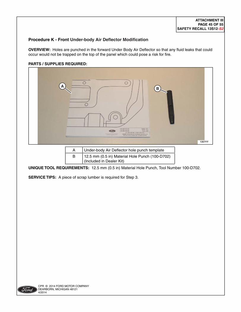
Procedure K - Front Under-body Air Defl ector Modifi cation
OVERVIEW: Holes are punched in the forward Under Body Air Defl ector so that any fl uid leaks that could occur would not be trapped on the top of the panel which could pose a risk for fi re.
PARTS / SUPPLIES REQUIRED:
1357YY
AB
A Under-body Air Defl ector hole punch template
B 12.5 mm (0.5 in) Material Hole Punch (100-D702) (Included in Dealer Kit)
UNIQUE TOOL REQUIREMENTS: 12.5 mm (0.5 in) Material Hole Punch, Tool Number 100-D702.
SERVICE TIPS: A piece of scrap lumber is required for Step 3.
ATTACHMENT IIIPAGE 46 OF 55
SAFETY RECALL 13S12-S2
CPR © 2014 FORD MOTOR COMPANYDEARBORN, MICHIGAN 481214/2014
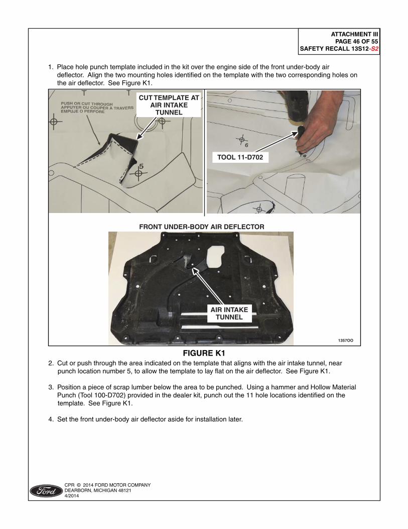
2. Cut or push through the area indicated on the template that aligns with the air intake tunnel, near punch location number 5, to allow the template to lay fl at on the air defl ector. See Figure K1.
3. Position a piece of scrap lumber below the area to be punched. Using a hammer and Hollow Material Punch (Tool 100-D702) provided in the dealer kit, punch out the 11 hole locations identifi ed on the template. See Figure K1.
4. Set the front under-body air defl ector aside for installation later.
FIGURE K1
1357OO
TOOL 11-D702
FRONT UNDER-BODY AIR DEFLECTOR
CUT TEMPLATE ATAIR INTAKE
TUNNEL
AIR INTAKETUNNEL
1. Place hole punch template included in the kit over the engine side of the front under-body air defl ector. Align the two mounting holes identifi ed on the template with the two corresponding holes on the air defl ector. See Figure K1.

ATTACHMENT IIIPAGE 47 OF 55
SAFETY RECALL 13S12-S2
CPR © 2014 FORD MOTOR COMPANYDEARBORN, MICHIGAN 481214/2014
Procedure L - Lower Active Grille Shutter (AGS) Modifi cation
OVERVIEW: The second and third row shutters in the lower Active Grille Shutter (AGS) assembly will be removed to provide additional airfl ow in the engine compartment.
PARTS / SUPPLIES REQUIRED: None
UNIQUE TOOL REQUIREMENTS: Coarse 18 tooth-per-inch hacksaw blade and hacksaw blade holder (commercially available).
SERVICE TIPS: Follow the procedure to remove the 2nd and 3rd row grille shutters from the bottom of the lower AGS assembly. Verify all remaining AGS Shutters are connected and move freely by moving the mechanism physically after modifi cation.
NOTICE: Place a suitable cover on the lower front bumper grille opening to protect the paint from damage during the cutting operation.
1. Locate the shutters in the 2nd and 3rd positions from the bottom of the lower AGS assembly through the lower front bumper grille opening. See Figure L1.
FIGURE L1
1357PP
2ND AND 3RD ROWFROM BOTTOM AGS ASSEMBLY
SHUTTERS
HAND SAW
PIVOT LOCATION2ND AND 3RD ROW
FROM BOTTOM AGS ASSEMBLY
SHUTTERS
2. Remove the 2nd and 3rd row shutters from the lower AGS assembly through the lower front bumper grille opening. See Figures L1.
a. Cut through the 2nd and 3rd row shutters at approximately 2-inches from center on both sides of the AGS assembly. b. Push the center portion of the 2nd and 3rd row shutters upward to disengage them from the center of the AGS assembly track. c. Bend the detached center portion of the 2nd and 3rd position grill shutters back and forth to break them apart and remove them. d. Slide the remaining LH and RH portions of the cut shutters out from their pivot locations at each side of the AGS assembly. e. Verify all remaining shutters move and do not bind.

ATTACHMENT IIIPAGE 48 OF 55
SAFETY RECALL 13S12-S2
CPR © 2014 FORD MOTOR COMPANYDEARBORN, MICHIGAN 481214/2014
Procedure M - Battery B+ Terminal Cable Routing Inspection and Tie-Strap Retention
OVERVIEW: Ensure the battery positive cable to the generator is routed correctly. If routed incorrectly, the cable may contact and chafe at the transmission lifting eye on top of the transmission. Upon inspection, if the cable is routed incorrectly, it must be routed properly and secured to the engine main wiring harness using a tie strap.
PARTS / SUPPLIES REQUIRED:
1357ZZ
A
A Tie-strap
UNIQUE TOOL REQUIREMENTS: None
SERVICE TIPS: None

ATTACHMENT IIIPAGE 49 OF 55
SAFETY RECALL 13S12-S2
CPR © 2014 FORD MOTOR COMPANYDEARBORN, MICHIGAN 481214/2014
1. Inspect the battery B+ terminal cable for improper routing and/or any signs of wire and insulation damage. See Figure M1.
- If the battery cable is damaged, replace it prior to proceeding. - A properly routed cable can be identifi ed by having the cable routed from the generator across the front of the engine and with the cable secured to the main engine wiring harness with a zip tie near the forward left side of the intake manifold. See Figure M1. - An improperly routed cable can be identifi ed by the cable being routed forward of the engine near the radiator, and is not attached to the main engine wiring harness with a zip tie. See Figure M2.
FIGURE M1
1357KK
CORRECT ROUTING
CLIP
CLIP
INSTALLTIE-STRAP
TRANSMISSION LIFTING EYE
BATTERYB+ CABLE
FIGURE M2
1357BL
CLIP
CLIP
BATTERYB+ CABLE
TRANSMISSION LIFTING EYE
IMPROPER ROUTING

ATTACHMENT IIIPAGE 50 OF 55
SAFETY RECALL 13S12-S2
CPR © 2014 FORD MOTOR COMPANYDEARBORN, MICHIGAN 481214/2014
2. If the battery positive terminal cable is routed improperly and isn’t damaged, pull it back through to the center of the engine compartment. Then re-route it up and near the front left side of the engine. Secure it to the main engine wiring harness using the tie-strap and existing clips as shown. See Figure M1.
• If required to disconnect the battery B+ terminal cable for rerouting, the battery negative cable must be disconnected. For additional information, refer to WSM Section 414-01. Reconnect the battery after the rerouting and reinstallation of the battery B+ terminal cable is completed. • If removed, tighten the battery B+ terminal cable to 12 Nm (106 lb-in).
3. Install the tie-strap provided in the kit to secure the starter/generator battery positive cable to the engine wire harness and prevent the cable from contacting the transmission lifting eye. See Figure M1.

ATTACHMENT IIIPAGE 51 OF 55
SAFETY RECALL 13S12-S2
CPR © 2014 FORD MOTOR COMPANYDEARBORN, MICHIGAN 481214/2014
Procedure N - Vehicle Reassembly and PCV Tube Retention, Powertrain Control Module (PCM) Reprogramming, and Engine Oil Level Indication Updates
OVERVIEW: The vehicle is reassembled, the cooling system is fi lled, pressure tested and bled; and a PCV tube retainer is installed. The PCM is reprogrammed and coolant level sensor operation is validated. The dipstick is replaced and an oil identifi cation label is attached to the engine cover to complete the repair.
PARTS / SUPPLIES REQUIRED:
A
B
C
1355AAA
A PCV Tube Retainer / Tie strap
B Engine Oil Dipstick (Kit -6750-)
C Engine Oil Fill Label (Kit -6750-)
D Motorcraft® Metal Brake Parts Cleaner (PM-4-A or PM-4-B)(Dealer Procured) (Not Shown)
E Motorcraft® Orange Antifreeze / Coolant Prediluted (VC-3DIL-B (U.S.) CVC-3DIL-B (Canada) / WSS-M97B44-D2)(Dealer Procured) (Not Shown)
UNIQUE TOOL REQUIREMENTS: None
SERVICE TIPS: Follow procedure steps to verify proper coolant fi ll.

ATTACHMENT IIIPAGE 52 OF 55
SAFETY RECALL 13S12-S2
CPR © 2014 FORD MOTOR COMPANYDEARBORN, MICHIGAN 481214/2014
NOTE: This procedure contains unique steps for reassembly, including installation of new components.
1. If disconnected previously, connect the battery B+ terminal cable. a. Disconnect the battery negative cable to ground. For additional information, refer to WSM Section 414-01. b. Install and tighten the battery B+ terminal cable to 12 Nm (106 lb-in). c. Connect the battery negative cable to ground. For additional information, refer to WSM Section 414-01.
NOTE: Remove protective covers that were placed over the turbocharger air intake system before re-installing components.
2. Install the turbocharger inlet pipe and connect the PCV hose to the turbocharger inlet pipe. See Figure A3.
• Tighten the turbocharger inlet pipe fasteners to 5 Nm (44 lb-in). • Tighten the turbocharger inlet pipe-to-turbocharger clamp to 5 Nm (44 lb-in).
3. Vacuum fi ll the cooling system. Refer to WSM Section 303-03 for coolant specifi cations.
• Do not bleed the cooling system at this time. • Coolant level should be fi lled to the "MAX" mark on the degas bottle.
4. Install a coolant pressure tester with adapter onto the degas bottle. Pressurize to 138 kPa (20 psi). Once pressure stabilizes, pressure should hold at 138 kPa (20 psi) for a minimum of 2 minutes. - If pressure test fails, the source of pressure loss must be identifi ed and repaired as appropriate before proceeding. Retest the cooling system, if required.
5. Vehicles built on or before July 11, 2012, AND identifi ed in OASIS as having program code 13Y03 open, proceed to "Fuel Line Jumper Inspection" within Attachment V. Once complete, continue with procedure below.
6. Install the air cleaner assembly. See Figure A2.
a. Install the air cleaner assembly. b. Attach the fresh air intake tube fl ap. c. Connect the mass air fl ow sensor electrical connector. d. Tighten the clamp to 5 Nm (44 lb-in).
7. Connect the EVAP line quick connect coupling to the air intake tube center section and install the retention clip. See Figure A1.

ATTACHMENT IIIPAGE 53 OF 55
SAFETY RECALL 13S12-S2
CPR © 2014 FORD MOTOR COMPANYDEARBORN, MICHIGAN 481214/2014
9. Install the front under-body air defl ector and retainers. See Figure A4.
10. Bleed the cooling system. For additional information, refer to WSM Section 303-03A.
11. Reprogram the PCM using IDS release 89.04A or higher. For additional information, Refer to "Procedure F" (Important Information for Module Reprogramming).
8. Install the PCV tube retainer / tie strap provided in the vehicle parts kit. See Figure N1.
a. Attach the clamp onto the PCV tube and secure. b. Wrap the tie strap around the air intake tube center section and tighten. c. Trim the excess length from the tie strap.
FIGURE N1
1357QQ
PCV TUBERETAININGTIE-STRAP
PCV TUBECLAMP
AIR INTAKE TUBECENTER SECTION

ATTACHMENT IIIPAGE 54 OF 55
SAFETY RECALL 13S12-S2
CPR © 2014 FORD MOTOR COMPANYDEARBORN, MICHIGAN 481214/2014
12. Using IDS select "Coolant Level Sensor Check". See Figure N2. • Follow the on screen instructions to complete the "Coolant Level Sensor Check" procedure.
FIGURE N2
1357BN
13. Remove the portable battery charger and install the battery cover.
14. Install the cowl panel. For additional information, refer to WSM, Section 501-02.
15. Install the engine appearance cover.

ATTACHMENT IIIPAGE 55 OF 55
SAFETY RECALL 13S12-S2
CPR © 2014 FORD MOTOR COMPANYDEARBORN, MICHIGAN 481214/2014
16. Clean the area on the engine appearance cover that the new engine oil fi ll label will be installed. Use Motorcraft® Metal Brake Parts Cleaner (PM-4-A or PM-4-B), and allow to dry. See Figure N3.
17. Install the new engine oil fi ll label onto the engine appearance cover as shown. See Figure N3.
FIGURE N3
1314A
NEW OIL FILL LABELNEW OIL DIPSTICK
ENGINE APPEARANCECOVER
18. Replace the vehicle's engine oil dipstick with the new engine oil dipstick. See Figure N3.
• Discard the original engine oil dipstick.
19. Verify that the engine oil level is correct, using the new engine oil dipstick.
• If the engine oil level is above the specifi ed level on the new engine oil dipstick, adjust the engine oil level as appropriate using normal procedures.
20. Perform any other open recalls.
21. Coolant level should be fi lled to the "MAX" mark on the degas bottle once the engine is cold, prior to returning the vehicle to the customer.

Vehicle Identification Number (VIN)
I I I I I I I IATTACHMENT IV
INSPECTION I CHECK SHEETSAFETY RECAll 13S12-S2
13512 VEHICLE INSPECTION I CHECK SHEETTechnician ID: Repair Order#:. _
Vehicle Mileage:. Repair Date:. _
Vehicle Build Date: Open FSA(s): _INSTRUCTIONS: Complete this Inspection / Check Sheet and attach / file it with the recall repair order
following completion.
1. Record any DTCs present. Check appropriate box.
D Pass - No DTCs present.D Fail - DTCs present.
If fail, document any DTCs retrieved below, and reference during "Procedure B".
2. Visually inspect the coolant level in the degas bottle. Check appropriate box.
D Pass - Coolant level is visible in the degas bottle.D Fail - Coolant level is not visible in the degas bottle, needed to add coolant.
If fail, document any repairs performed below.
3. Pressure test cooling system. Check appropriate box.
D Pass - Cooling system holds pressure for 2 minutes.D Fail - Cooling system does not hold pressure for 2 minutes.
If fail, document any repairs performed below.
4. Visually check for coolant leaks with the system under pressure. Check appropriate box.
D Pass - No coolant leak(s) found.D Fail - Coolant leak(s) found.
If fail, document any repairs performed below.
5. Visually inspect the engine oil level and check for engine oil leaks at the rear surface of cylinder head,above exhaust manifold. Check appropriate box.
D Pass - No engine oilleak(s) found.D Fail - Engine oilleak(s) found.
D Pass - Correct oil level.D Fail - Engine oil not at correct level.
If fail, document any repairs performed below.
CPR © 2014 FORD MOTOR COMPANYDEARBORN, MICHIGAN 481214/2014

ATTACHMENT VPAGE 1 OF 8
SAFETY RECALL 13S12-52
CERTAIN 2013 MODEL YEAR ESCAPE VEHICLES EQUIPPED WITH A 1.6L ENGINE- FUEL LINE JUMPER INSPECTION
OVERVIEW
In certain 2013 Escape models equipped with a 1.6L engine built on or before July 11, 2012; the servicefuel line jumper that was installed during Safety Recall 12S35 may have been installed incorrectly. Animproperly positioned fuel line jumper may chafe on other engine components over a period of time andleak fuel.
At this time, dealers are to inspect the fuel line jumper for correct installation and replace it only if it is notinstalled properly.
Updated information for Safety Recall 13S12 will be provided to dealers late in the first quarter of 2014when it is anticipated that repair instructions and parts ordering information will be available to supportconcerns for a risk of overheating that may result in engine fires.
SERVICE PROCEDURE
Fuel Line Jumper Inspection (Certain Vehicles Built On Or Before July 11, 2012 andIdentified in OASIS by Program Code 13Y03)
1. Using OASIS determine if "Safety Recall 12S35" has been performed on the vehicle.
- If "Safety Recall 12S35" was not previously performed (12S35 is open in OASIS), perform"Safety Recall 12S35" and also claim the "Inspection Passed" labor operation.
- If "Safety Recall 12S35" ~ previously performed on the vehicle (12S35 is not open in OASIS),continue with this procedure to inspect the fuel line jumper.
NOTICE: When working with liquid or vapor tube connectors, make sure to use compressed air toremove any foreign material from the connector retaining clip area before separatingfrom the tube or damage to the tube or connector retaining clip can occur. Apply cleanengine oil to the end of the tube before inserting the tube into the connector.
NOTICE: Do not use any tools to disconnect the quick connect coupling on the air intake tubecenter section. The use of tools may cause a deformity in the clip components whichmay cause leaks.
NOTICE: Whenever turbocharger air intake system components are removed, always cover openports to protect from debris. It is important that no foreign material enter the system.The turbocharger compressor vanes are susceptible to damage from even smallparticles. All components should be inspected and cleaned, if necessary, prior toinstallation or reassembly.
2. Remove the engine appearance cover.
CPR @ 2014 FORD MOTOR COMPANYDEARBORN, MICHIGAN 481214/2014

ATTACHMENT VPAGE 2 OF8
SAFETY RECALL 13S12-S2
3. Disconnect the EVAP line quick connect coupling from the air intake tube center section. Set the clipaside for re-installation to prevent it from falling into the engine compartment. See Figure 1.
4. Loosen the 2 clamps and remove the air intake tube center section. See Figure 1.
• To install, tighten to 5 Nm (44 Ib-in).
CPR e 2014 FORD MOTOR COMPANYDEARBORN, MICHIGAN 481214/2014
EVAP LINEQUICK CONNECT
COUPLING
FIGURE 1

ATTACHMENT VPAGE 3 OF 8
SAFETY RECALL 13S12-52
5. Inspect the fuel line jumper orientation. See Figure 2, 3, and 4.
- There are three different style service Fuel Line Jumpers that may have been installed duringSafety Recall 12S35.
• Type 1 - Plastic line with fuel pulse damper.• Type 2 - Plastic line without fuel pulse damper.• Type 3 - Plastic line without fuel pulse damper and with silver foil protective covering.
For all three of these line types, the correct installation is with the white "ENGINE SIDE" tagon the line closest to the engine connection side. See Figure 2, 3, and 4, for examples of correctinstallations.
- If the fuel line jumper is installed as shown, with the "ENGINE SIDE" tag located closest to theengine (front of vehicle), no further action is required. Reassemble the vehicle by reversing theremoval procedure.
- If the fuel line jumper ~ installed as shown, with the white "ENGINE SIDE" tag locatedclosest to the engine (front of vehicle), proceed to "Fuel Line Jumper Replacement".
1357N
FIGURE 2
CPR e 2014 FORD MOTOR COMPANY4111*e- DEARBORN, MICHIGAN 481214/2014

ATTACHMENT VPAGE40F8
SAFETY RECALL 13S12-S2
1357L
FIGURE 3
13S7M
FIGURE 4
I CPR @ 2014 FORD MOTOR COMPANY
tN!"~ilftili'!I.!IF' DEARBORN, MICHIGAN 48121- •••• - 412014

ATTACHMENT VPAGE 5 OF8
SAFETY RECALL 13512-S2
Fuel Line Jumper Replacement
& WARNING: Before beginning this service procedure, review the Safety Warnings contained inWorkshop Manual (WSM), Section 100-00.
NOTICE: Do not loosen any fittings or plugs on the fuel injection pump.
NOTE: The fuel line jumper should only be replaced if the existing line on the vehicle is verified to beinstalled incorrectly.
1. Remove the two retainers and the lower passenger side Instrument Panel (IP) insulator, to access theBody Control Module (BCM). See Figure 5.
LOWER PASSENGER SIDEINSTRUMENT PANEL (IP)
INSULATOR 1235A
FIGURE 52. Remove Fuse #56 (Fuel Pump Module fuse), from the BCM. See Figure 6.
12358
FIGURE 6

ATTACHMENT VPAGE 6 OF 8
SAFETY RECALL 13512·52
3. Start the engine and allow it to idle until the engine stalls.
4. Crank the engine for approximately five seconds to make sure that the fuel rail pressure is released.
5. Turn the ignition switch to the OFF position.
6. Disconnect the battery ground cable. Refer to WSM, Section 414-01.
7. Remove the two bolts and position the master cylinder reservoir aside. See Figure 7.
12350
FIGURE 7
.-:ii!! CPR © 2014 FORD MOTOR COMPANY•••.'IIIII!IiIAi!~I1'iiI.!!JIII'DEARBORN, MICHIGAN 48121
•• - 4/2014

ATTACHMENT VPAGE 70F8
SAFETY RECALL 13S12-52
NOTICE: Fuel injection equipment is manufactured to very precise tolerances and fine clearances.It is essential that absolute cleanliness is observed when working with thesecomponents or component damage can occur. Always install plugs to any open orificesor tubes.
NOTE: Use a shop towel to absorb any residual fuel that is released when disconnecting the fuel lines.
8. Remove and discard the fuel line jumper. See Figure 8.
• Using Special tool 310-S039 or equivalent disconnect the fuel line quick connect couplings.
NOTE: The fuel line jumper shown is installed in the incorrect orientation with the "ENGINESIDE" tag not located closest to the engine (further from front of vehicle).
1357K
FIGURE 8
e CPR e 2014 FORD MOTOR COMPANY-\r- DEARBORN, MICHIGAN 481214/2014

ATTACHMENT VPAGE 80F8
SAFETY RECALL 13S12-S2
Fuel Line Jumper Installation
NOTE: The new fuel line jumper design does not have a fuel pulse damper.
NOTE: Once the fuel line jumper is installed, the yellow "ENGINE CONNECTION" tag should bepositioned closest to the engine (front of vehicle). See Figure 9.-_...•.
FIGURE 9NOTICE: When connecting the new fuel line jumper, do not force it in at an angle or damage to
the fuel line o-rings may occur. Minimal effort is required to connect the fuel line. Ifexcessive effort is observed, re-align and try again.
1. To install the new fuel line jumper, reverse the removal procedure.
• Be sure that the yellow "ENGINE CONNECTION" tag is positioned closest to the engine (front ofvehicle) before attachment. See Figure 9.
• Connect the engine side of the fuel line jumper first.• Push the fuel line jumper connectors onto the lines. Listen for a click, then pull on the connectors
to verify proper attachment.• After installation is complete, carry out a Key ON Engine OFF (KOEO) visual inspection forfuel leaks.
CPR © 2014 FORD MOTOR COMPANYDEARBORN, MICHIGAN 481214/2014


![Automated Autonomous Vehicles: Prospects and …thinking Transportation 2020-2030” [4]. The report claimed that vehicles equipped with gasoline fueled internal combustion engine](https://img.pdfslide.net/doc/110x75/5f206a0c09f2a96278431928/automated-autonomous-vehicles-prospects-and-thinking-transportation-2020-2030a.jpg)