Embed Size (px)
Citation preview

from the archives of Bob Grove MONITORING TIMES 1
N o subject is more widely discussed in the radio field as antennas, and with good reason; after you select
your radio equipment, no accessory is more important. There are many myths surrounding antennas, and we’re going to put them to rest in this series.
Radio Waves: Some Basics When we connect a wire between the two terminals of a battery, electric current flows. This current generates a combined electric and magnetic energy “field,” a zone which extends at the speed of light into space. When we break the circuit, the energy field collapses back onto the wire. If we reverse the connections back and forth rapidly, each successive pulse’s electrical (positive and negative) charges and magnetic (north and south) poles reverse as well. This simulates a basic radio wave which consists of a magnetic and electric field vibrat-ing simultaneously, or in phase. The electric field (“E” for electro-motive force, measured in volts) is parallel to the axis of the wire, while the magnetic field (“H” named after researcher Joseph Henry) is perpendicular to it. This field is described as electromagnetic. Familiar illustrations depict-ing radio waves as wavy lines or crosshatched arrows are graphic representations only. There are no “lines of force” as implied when iron filings line up during magnet demonstrations; those filings line up because they all become little magnets, attracting and repelling one another. Radio waves are only a continuous field of energy which, like a beam of light, is strongest at its source, weakening with distance as it spreads its energy over an ever-widening area. In fact, radio waves and light waves differ only in frequency over a continuous electro-magnetic spectrum, with higher-frequency light having greater energy and the ability to be seen by some living organisms. Scientists even refer to an antenna as being illuminated by radio energy. Radio waves can be reflected by buildings, trees, vehicles, moisture, metal sur-faces and wires, and the electrically-charged ionosphere. They can be refracted (bent) by
boundaries between air masses, and they can be diffracted (scattered) by a ground clutter of reflective surfaces. Radio and light waves travel through the vacuum of space approximately 186,000 miles (300 million meters) per second, but when they pass through a dense medium, they slow down; this velocity factor, is given as a specifica-tion for transmission lines. When we specify antenna and transmission line lengths, these are electrical wavelengths which are shorter than free-space wavelengths because of this reduction in speed.
Propagation We refer to the behavior of radio waves as they travel over distance as propagation. Ground waves stay close to the earth’s surface, never leaving the lower atmosphere. They are severely attenuated (reduced), rarely reaching more than a few hundred miles even under ideal conditions. Surface waves, the lowest ground waves, often reach-ing their destination by following the curvature of the earth. Space waves are the line-of-sight ground waves which travel directly from antenna to antenna. Space waves at VHF and UHF, when encountering abrupt weather boundary changes, experience temperature inversions and ducting as well as other influences that can funnel signals into significantly extended ground wave coverage. At the upper reaches of our atmo-sphere, ultraviolet rays (UV) from the sun ionize (electrically charge) the air atoms, lending the name ionosphere to this highest zone of the earth’s atmosphere. Radio waves which reach these ionized layers, averaging 25-200 miles high, are called sky waves The lowest regions of the ionosphere, the D and E layers, are influenced directly by sunlight; their effects begin at sunrise, peak at noon, and disappear after sunset. They absorb radio signals. In other words, the longer the wavelength
(that is, the lower the frequency), the more the absorption. This explains why daytime recep-tion below roughly 10 megahertz (MHz) is so poor. But, the E layer also reflects shorter-wavelength (higher frequency) signals back to Earth; the higher the frequency, the more the reflection. This is what provides distance (DX) on the higher shortwave frequencies. Most DX, however, is produced by the next region up, the F layer, which retains its elec-trical charge well into the night, reflecting signals back to the earth over great distances. All of these solar influences increase during the maximum sunspot cycle every 11 years, then gradually diminish again. The earth itself can reflect radio waves, allowing a phenomenon called multihop; combinations of earth reflections and iono-spheric refractions producing as many as five skips! More skips than that would be attenu-ated by ionospheric absorption and terrestrial
ALL ABOUT ANTENNAS Part 1 of a Series
By Bob Grove W8JHD, Publisher, Monitoring Times
Signal propagation is a combination of ground waves and sky waves.

2 from the archives of Bob Grove
scattering, rendering the signal unreceivable. Internet sites like www.hfradio.org/propa-gation.html publish continuously-updated radio propagation forecasts, and a variety of prediction computer programs are available elsewhere, allowing the user to plan ahead for the most productive use of the spectrum. Tropospheric scattering in the E and F2 layers is fairly common in the 30-50 MHz spectrum, especially during the daytime and during sunspot peaks. It favors the east in the morning and the west in the afternoon. At VHF and UHF, ionospheric propagation is rare. Some sporadic E skip, lasting from a few minutes to an hour or more, may occur in the 50-200 MHz range. It is caused by erratic clouds of ionization at an altitude of 75-100 miles. A similar phenomenon is produced when meteors enter the E layer. At such high speeds, the meteor vaporizes, producing an ionized trail which is capable of reflecting VHF signals back to earth 1000 more miles away, most dramatically in the 50-80 MHz spectrum. It is estimated that some 200 tons of me-teor material, from visible to dust size, strikes the earth every day; much more vaporizes in the upper atmosphere. Because of this constant bombardment, there are completely automated systems relying on this technique for long-distance data transfer.
Patterns The shape of the field of energy emit-ted by a transmitting antenna, as well as the geometric response by a receiving antenna, is known as its pattern. It may be a simple donut shape surrounding the axis of the wire as in a
half-wave, or smaller, dipole, called a doublet, or it may be multi-lobed, as in a multiple-wavelength antenna, called a longwire. The elevation pattern, variously called radiation angle, takeoff angle, maximum am-plitude elevation, and launch angle, is affected by height above ground, length of the antenna element(s), and the presence of nearby metal, including other antenna elements. It is an in-tegral part of an antenna’s gain characteristics which we will discuss in a later issue.
The higher the frequency, the shorter the wavelength and the easier it is for a signal to get through an opening in an absorptive or reflective enclosure.
Nearby trees, buildings and hills take their toll, too. Locating an antenna inside a large building with steel frame and metal reinforce-ments may attenuate signals up to 25 dB at VHF and UHF, according to one study. Brick walls, slate or tile roofs can account for 6 dB, even more when wet. Shorter wavelengths (900 MHz) get through small windows in shielded walls where longer wavelengths (150 MHz) do not.
Location, Location, Location…
The Radio Horizon Radio waves, like light waves, follow the line of sight. Because of the curvature of the earth, higher antennas “see” a farther horizon. Assuming a flat, unobstructed terrain, the visual horizon is about 8 miles for a 30-foot-elevated antenna, increasing to only 16 miles at 120 feet! Notice the square law effect: it requires roughly four times the height to get twice the distance. Once an antenna is high enough to “see” past nearby obstructions, it takes at least double that height to notice any improvement. The lower the frequency, the more radio waves are capable of following the curvature of the earth beyond the visual horizon. Typical base-to-mobile communications ranges are about 50 miles in the 30-50 MHz band, 30 miles at 150-174 MHz, 25 miles at 450-512 MHz, and 20 miles at 806-960 MHz. Obviously, these distances will vary depending upon radiated power, receiver sensitivity, antenna gain, elevation and location. Although the higher the antenna the better, coax cable losses may compromise any signal improvement; the higher the frequency, the worse those losses. For example, at 450 MHz, extend-ing a 30-foot antenna to 60 feet could increase signal strengths by 5 dB, but if you are using common RG-58/U coax, signal strengths may be attenuated by the same amount, resulting in no improvement at all! At 800 MHz, using this small diameter, lossy RG-58U, signals would get worse with height! Worst of all is thin RG-174U which has all the bad characteristics; in long lengths at UHF, you might as well short-circuit your antenna connector! Always use low-loss cable such as the following, listed in increasing performance: RG-8/X, RG-8/U, Belden 9913, or 1/2” foam (Andrews), Heliax (all 50 ohm cables); or RG-59/U, RG-6/U or RG-11/U (72 ohm cables).
Terrain, trees, wiring, metal siding, nearby buildings and other reflective surfaces all affect antenna performance. The lower the antenna, the more obstructed it is likely to be. A basement would be a very poor antenna location. Signals are unpredictably reflected by metal and wiring in and on the walls and ceiling; nearby electric and electronic appliances invite interference to reception; soil absorbs transmitted energy and also reflects signals upward; and signals come mostly from overhead (there aren’t many there) rather than from the horizon.
Antennas are designed to favor certain direc-tions, both for transmitting and receiving. The lower the frequency, the more the signal is capable of following the contour of the ter-rain, and the less likely it is to be absorbed by trees and foliage. One study showed that with dense trees and vertical polarization, attenu-ation at 30 MHz is about 3 dB, increasing to 10 dB at 100 MHz.
from the archives of Bob Grove MONITORING TIMES 3
L ast month we examined some of the char-acteristics (peculiarities?) of radio waves and the importance of proper placement of
an antenna. This month we’ll take a close look at the antenna itself.
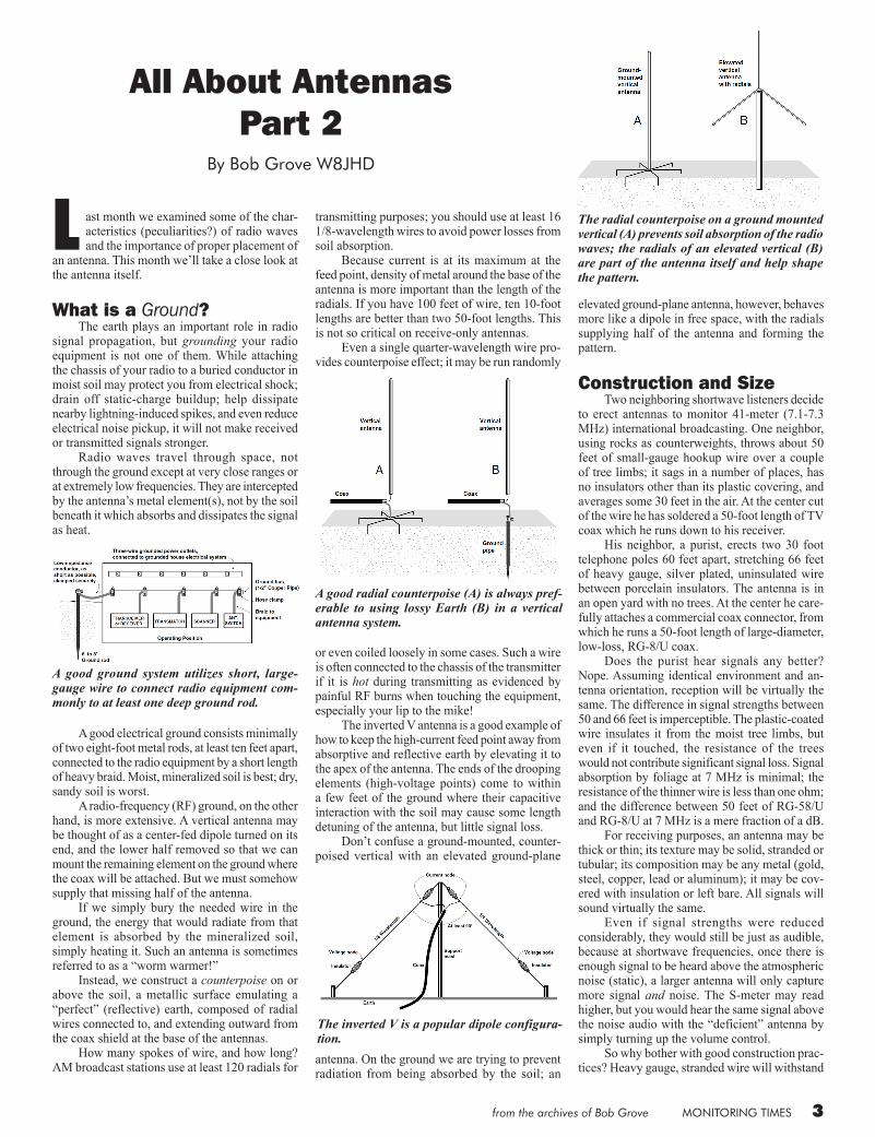
What is a Ground? The earth plays an important role in radio signal propagation, but grounding your radio equipment is not one of them. While attaching the chassis of your radio to a buried conductor in moist soil may protect you from electrical shock; drain off static-charge buildup; help dissipate nearby lightning-induced spikes, and even reduce electrical noise pickup, it will not make received or transmitted signals stronger. Radio waves travel through space, not through the ground except at very close ranges or at extremely low frequencies. They are intercepted by the antenna’s metal element(s), not by the soil beneath it which absorbs and dissipates the signal as heat.
A good electrical ground consists minimally of two eight-foot metal rods, at least ten feet apart, connected to the radio equipment by a short length of heavy braid. Moist, mineralized soil is best; dry, sandy soil is worst. A radio-frequency (RF) ground, on the other hand, is more extensive. A vertical antenna may be thought of as a center-fed dipole turned on its end, and the lower half removed so that we can mount the remaining element on the ground where the coax will be attached. But we must somehow supply that missing half of the antenna. If we simply bury the needed wire in the ground, the energy that would radiate from that element is absorbed by the mineralized soil, simply heating it. Such an antenna is sometimes referred to as a “worm warmer!” Instead, we construct a counterpoise on or above the soil, a metallic surface emulating a “perfect” (reflective) earth, composed of radial wires connected to, and extending outward from the coax shield at the base of the antennas. How many spokes of wire, and how long? AM broadcast stations use at least 120 radials for
transmitting purposes; you should use at least 16 1/8-wavelength wires to avoid power losses from soil absorption. Because current is at its maximum at the feed point, density of metal around the base of the antenna is more important than the length of the radials. If you have 100 feet of wire, ten 10-foot lengths are better than two 50-foot lengths. This is not so critical on receive-only antennas. Even a single quarter-wavelength wire pro-vides counterpoise effect; it may be run randomly
or even coiled loosely in some cases. Such a wire is often connected to the chassis of the transmitter if it is hot during transmitting as evidenced by painful RF burns when touching the equipment, especially your lip to the mike! The inverted V antenna is a good example of how to keep the high-current feed point away from absorptive and reflective earth by elevating it to the apex of the antenna. The ends of the drooping elements (high-voltage points) come to within a few feet of the ground where their capacitive interaction with the soil may cause some length detuning of the antenna, but little signal loss. Don’t confuse a ground-mounted, counter-poised vertical with an elevated ground-plane
antenna. On the ground we are trying to prevent radiation from being absorbed by the soil; an
elevated ground-plane antenna, however, behaves more like a dipole in free space, with the radials supplying half of the antenna and forming the pattern.
Construction and Size Two neighboring shortwave listeners decide to erect antennas to monitor 41-meter (7.1-7.3 MHz) international broadcasting. One neighbor, using rocks as counterweights, throws about 50 feet of small-gauge hookup wire over a couple of tree limbs; it sags in a number of places, has no insulators other than its plastic covering, and averages some 30 feet in the air. At the center cut of the wire he has soldered a 50-foot length of TV coax which he runs down to his receiver. His neighbor, a purist, erects two 30 foot telephone poles 60 feet apart, stretching 66 feet of heavy gauge, silver plated, uninsulated wire between porcelain insulators. The antenna is in an open yard with no trees. At the center he care-fully attaches a commercial coax connector, from which he runs a 50-foot length of large-diameter, low-loss, RG-8/U coax. Does the purist hear signals any better? Nope. Assuming identical environment and an-tenna orientation, reception will be virtually the same. The difference in signal strengths between 50 and 66 feet is imperceptible. The plastic-coated wire insulates it from the moist tree limbs, but even if it touched, the resistance of the trees would not contribute significant signal loss. Signal absorption by foliage at 7 MHz is minimal; the resistance of the thinner wire is less than one ohm; and the difference between 50 feet of RG-58/U and RG-8/U at 7 MHz is a mere fraction of a dB. For receiving purposes, an antenna may be thick or thin; its texture may be solid, stranded or tubular; its composition may be any metal (gold, steel, copper, lead or aluminum); it may be cov-ered with insulation or left bare. All signals will sound virtually the same. Even if signal strengths were reduced considerably, they would still be just as audible, because at shortwave frequencies, once there is enough signal to be heard above the atmospheric noise (static), a larger antenna will only capture more signal and noise. The S-meter may read higher, but you would hear the same signal above the noise audio with the “deficient” antenna by simply turning up the volume control. So why bother with good construction prac-tices? Heavy gauge, stranded wire will withstand
All About AntennasPart 2
By Bob Grove W8JHD
A good ground system utilizes short, large-gauge wire to connect radio equipment com-monly to at least one deep ground rod.
A good radial counterpoise (A) is always pref-erable to using lossy Earth (B) in a vertical antenna system.
The inverted V is a popular dipole configura-tion.
The radial counterpoise on a ground mounted vertical (A) prevents soil absorption of the radio waves; the radials of an elevated vertical (B) are part of the antenna itself and help shape the pattern.

4 from the archives of Bob Grove
ice, wind loading, and flexing better than thin solid wire, and it will radiate transmitted power more efficiently. Commercially made center insulators with built-in connectors are more rigid and water resistant than soldered connections and they can be easily disconnected for servicing or inspection. Sturdy, insulated suspension is more durable over time, and keeping antennas away from tree foliage may avoid some signal loss at higher frequencies.
Skin Effect A thin, hollow, metal tube is just as efficient in conducting and radiating radio-frequency energy as a solid wire of the same diameter and material. This is because RF energy barely dips below the surface of the conductor, and the higher the frequency, the shallower the depth. The larger the surface, the less resistance, which would waste power as heat. Skin depth varies inversely with the square root of the conductivity and the per-meability (magnetic attraction) of the metal; the better the conductor, the deeper the skin effect. At microwave frequencies (10 GHz), the skin depth of silver, an excellent conductor, is 0.64 micrometers (µm), while that of aluminum, a poorer conductor, is 0.80 µm. Iron is a very poor conductor and has high permeability; its skin depth is only 1/7 that of copper, making it a poor choice as a conductor at radio frequencies.
Antenna Size The energy-intercepting area of an antenna is called its aperture (another similarity to light as in the aperture of a camera lens) or capture area; the larger its aperture, the more signal it captures. Curiously, a large antenna is not necessarily bet-ter at transmitting (or receiving) than a smaller antenna. If a small element can be designed to be just as efficient as a large antenna, and radiates the same pattern, there is no benefit in using a larger antenna unless it can be configured to offer gain, which comes from shaping the directionality of the antenna. Similarly, all antennas of the same size (wire dipoles, folded dipoles, fans, trap anten-nas, cages, or any other) radiate the same amount of power. Their relative advantages come from pattern directivity. The U.S. Coast Guard found several de-cades ago that a five-foot antenna was adequate for HF reception 100% of the time. Remember, the purpose of an antenna is to detect enough signal to overcome the receiver’s own internally-generated noise; once that is accomplished, more signal only means more atmospheric noise with its attendant interference from strong-signal overload. Below approximately 50 MHz, atmospheric noise (static) becomes increas-ingly worse the lower we tune. This background hiss is a composite of thousands of lightning strikes occur-ring simultaneously, around the world. Once we detect enough signal to overcome
the receiver’s own self-generated circuit noise, a larger aperture will only increase the atmospheric noise right along with the signal. If the noise is locally generated (power lines or an electrically-noisy neighbor, for example) a beam or loop antenna can be rotated away from the source of the noise to null the interference, hopefully toward the direction of the signal as well. As we tune upwards from 50 MHz, atmo-spheric noise diminishes; therefore, larger and better-matched antenna systems do improve reception because they help overcome receiver noise, which can be higher than atmospheric noise at VHF and UHF frequencies. Ultimately, once the aperture is great enough to overcome receiver noise at these higher frequencies, larger aperture will only pick up more noise (just as at the lower frequencies) so directivity should be the goal for better reception.
Antenna Gain Signal improvement may come from a larger aperture, or from intentionally distorting (shaping) the field to produce a narrower pattern. While larger aperture increases background noise as well as signal strengths, directivity favors one or more directions at the expense of others. This reduces overall pickup (better signal-to-noise-ratio), con-centrating on a target direction for receiving and/or transmitting, and reducing reception interfer-ence from the sides and back. Such pattern re-direction often refers to front-to-back ratio and side-lobe rejection, describing how improvement in one direction is accompanied by the desirable loss in other directions. The pattern can be shaped by adding parasitic elements, which are unconnected but secured to the boom, called reflectors and direc-tors (see Yagi below). Feed point mismatch does not affect an antenna’s gain or pattern. Adding a second identical antenna separated by ½ wavelength and connected in phase, known
as stacking will increase transmitted and received sig-nal strengths by 3 dB, regard-less of the original gain. Thus, two 1-dB-gain antennas will provide 4 dB total gain, and two 20-dB-gain intercon-nected antennas will provide 23 dB total gain. Antenna performance is usually compared to a half-wave dipole reference. Some manufacturers compare the gain of their antennas to an “isotropic” radiator which is a theoretical (and nonexistent) antenna that has a spheri-cal radiation pattern. This gives manufacturers a 2.1 dB
higher gain claim than if they compared it to a real antenna: a half-wave dipole. Unless the claimed gain figure is followed by dBd or dBi, referencing a dipole or isotropic radiator in free space, it is meaningless and suspect. Assuming we run the transmission line away at right angles from the antenna for at least a quarter wavelength, the location of the feed point causes very little distortion of the pattern, but the impedance selection varies dramatically. Is a good transmitting antenna always a good receiving antenna? Yes, if its aperture is large enough to capture enough signal to overcome receiver noise. The law of reciprocity states that if an antenna system efficiently radiates a signal into space, it will just as efficiently deliver an intercepted signal to a receiver. Is a good receiving antenna a good trans-mitting antenna? Not necessarily. If randomly erected, it may be susceptible to power loss due to impedance mismatch. Its pattern will be unpre-dictable and reactance may shut down a transmit-ter with built-in protection against mismatches.
Arrays Depending upon its thickness, taper and length, a mass of metal, brought within one-quarter-wavelength of a radiator (the driven element, connected to the feed line), will interact with the field, focusing (there’s that light analogy again!) the energy to produce directivity or gain. Probably the best known of these combina-tions is the Yagi-Uda array, named for the two Japanese scientists who developed the antenna in 1928. While Uda actually did all the develop-mental work, Yagi published the results, so the antenna, as fate would have it, usually bears his name alone.
Curiously, the Japanese did not use the Yagi in World War II. The modern Yagi consists of a half-wave-length driven element, a single rear reflector about 5% longer, and one or more forward directors about 5% shorter. The elements are usually spaced 0.15-0.2 wavelengths apart. Depending upon the number of directors, a Yagi may have six to twenty decibels (6 - 20 dBd) gain over a half-wave dipole in free space. There are many computer programs available in handbooks and on the Web for designing Yagi as well as other effective antennas.
Next Month : What do we mean by “matching” an an-tenna? What is “impedance?” Is it possible to re-motely “tune” an antenna for best performance? Stay tuned for the next thrilling installment!
Atmospheric noise decreasing with frequency.
Stacking any two identical antennas, regardless of their individual gain, will increase the total gain by 3dB.
The Yagi is a popular beam antenna with forward gain.

from the archives of Bob Grove MONITORING TIMES 5
All About AntennasPart 3
By Bob Grove W8JHD
L ast month we discussed the many physi-cal aspects of antenna design, not only in construction but in location. Now
let’s take a close look at some of the electrical considerations.
Matching the System The term “impedance matching” always comes up when referring to an antenna and transmission line. To impede means to oppose, so what is being opposed in an antenna system? When a battery is connected to a light bulb, the resistance of the filament is the impedance, dissipating the opposed energy as heat and light. Ohm’s law reveals that there is a simple relation-ship between resistance, voltage and current. When a transmitter is connected to an antenna in free space, RF energy is radiated into space; the voltage and current are controlled both by the antenna’s radiation resistance and any capacitive or inductive reactance which may be present. Why does an open circuit like a dipole accept and radiate power? An antenna is a spe-cialized form of transmission line; it is coupled to space, which has an impedance of 377 ohms. The center feed point impedance of a half-wave dipole, however, is much lower than that.
Resonance The impedance of an antenna is a combina-tion of radiation resistance, conductor resistance, and reactance. Radiation resistance is desirable; it’s what accepts power and radiates it into space. Conductor resistance, however, wastes power as heat. Reactance opposes incoming energy; it is caused when an antenna is too long or too short at a particular frequency, so that when the wave (signal voltage) traveling along the antenna is reflected from the ends, it returns to the feed point “out of phase” with the incoming wave. A half-wave antenna is naturally “reso-nant”; an arriving signal travels that half-wave length in half its cycle, then reflects back in the other direction, finishing that cycle when it returns to its starting point, the electromagnetic equivalent of a vibrating guitar string. Measurements will reveal maximum cur-rent (and minimum voltage) at the center, and maximum voltage (minimum current) at the ends of the wire. A multiple-half-wave (full-wave, wavelength-and-a-half, etc.) antenna will have a standing wave on every half-wavelength section.
Radiation Resistance An infinitely-thin, half-wave dipole in free space (at least several wavelengths away from other objects) would have a center feed point impedance (radiation resistance) of 73 ohms. Constructed of normal wire the impedance is
closer to 65 ohms; if thicker tubing, 55-60 ohms. This impedance rises as we move the feed point off center. If we use a folded dipole (See figure.) the feed point impedance rises to about 300 ohms. Proximity to the earth’s surface also alters
the feed point resistance of a horizontal dipole, typically dropping from 100 to nearly 0 ohms as the antenna is lowered from 0.33 wavelengths to the earth’s surface, and fluctuating between 60 and 100 ohms at heights between 0.33 and 1 wavelength. Vertical dipoles fare better, since their pat-
terns do not radiate directly downward where they would interact with the earth. Once elevated at least 0.25 wavelength, their impedance re-mains a relatively constant 70 ohms. A vertical antenna with drooping radials has lower impedance, nominally 50 ohms; if those radials were horizontal (at right angles to the vertical element), the feed-point impedance would be about 35 ohms. If 50-ohm coax is attached to an antenna’s 50-ohm feed point, we have a perfect (1:1 ratio) impedance match, but if that 50 ohm coax is at-tached either to a 25 or 100 (50/25 or 100/50), is that bad? No. Is 3:1? No. The simple fact is that if there is no resis-tive loss in the feed line or antenna (of course there always is), 100% of the generated power will be radiated by the antenna regardless of the mismatch. What really happens with an impedance mismatch? Some of the signal voltage reflects back from the antenna junction through the coax to the transmitter where it is re-reflected and
eventually radiated into space. The higher the voltage (that is, the worse the mismatch), the more power is absorbed by the resistive insula-tion, heating it. That’s where low-loss coax is important. An impedance mismatch does not produce radiation from the feed line. When receiving, all signal voltage gath-ered by a perfectly matched antenna is fed to the receiver, but with a mismatch, the reflected signal is radiated back into space. In practice, this is usually of minor consequence, especially at HF and below, where atmospheric noise is a dominant influence on signal interference.
The Transmission Line In the early days of radio when open-wire transmission lines were common, the voltage fields produced by standing waves would light up bulbs and deflect meters brought near the lines; nowadays, with the near-universal use of coaxial cable which encloses the electrostatic fields, such measurements are not as easy. Connecting an unbalanced line (coax) to a balanced antenna can cause RF currents to flow on the outside of the line, but these are not stand-ing waves. So what gives a transmission line its characteristic impedance (surge impedance)? A feed line can be considered as a radio-frequency, low-pass filter consisting of an infinite number of series inductances shunted by an infinite number of parallel capacitances. The impedance of this distributed network
is theoretical, based upon the dielectric constant of the insulation, the spacing of the conductors, no losses, and infinite length. While the most common feed line imped-ances are 50, 75 and 300 ohms (TV twin lead), there are more than two dozen commercially-available impedances from 32 to 600 ohms.
So why 50 or 75 ohms? Why have we chosen impedance standards like 50 and 75 ohms for coax? For transmitters, the best power-handling capability is at 77 ohms, while the best voltage tolerance occurs below 30 ohms. 50 ohms is a good compromise and it matches several standard antenna designs. For receiving purposes, 75 ohms is op-timum for low coax losses, so it was adopted by the cable TV industry. Conveniently, it also matches several antenna designs. The impedance a transmitter or receiver “sees” when it is mismatched to a length of transmission line connected to an antenna is a composite of the length of the line along with its losses, the SWR (see “Traveling Waves” below), and the load (feed point impedance of the antenna to which it is connected). If they are all properly matched, however, the impedance is determined only by the characteristic of the line.

6 from the archives of Bob Grove
Magical line lengths Trick No.1: The impedance measured at the bottom of an electrical-half-wavelength transmission line (or any whole-number mul-tiple of a half-wavelength), regardless of the characteristic impedance of the feed line, is the feed point impedance of the antenna.
For example, if, at some frequency, an antenna has a feed point impedance of, say, 143 ohms, then we will read 143 ohms at the bottom of a 50-, 72- or 300-ohm, electrical half-wavelength line connected to it. Keep in mind that this is an electrical half-wavelength; we must multiply the free-space half-wavelength by the velocity factor of the coax. For example, a half-wavelength at 14 MHz is 33 feet; using coax with a velocity factor of 66% would mean that you would actually cut the line to a length of 22 feet.
Trick No.2: We can use a quarter-wave-length piece of transmission line as an imped-ance-matching transformer using the formula:
For example, by substituting actual values in the solution below, if we wish to attach a 100-ohm antenna to a length of 50 ohm cable, we can insert a quarter-wavelength matching stub of 70 (often marked 72 or 75) ohm cable.
= = 70.7 ohms
Don’t forget to multiply the free-space quarter-wavelength by the velocity factor and shorten the length of the cable accordingly. For example, a quarter-wavelength at 14 MHz is 234/14, or 16.7 feet; using coax with a velocity factor of 66%, the actual physical length would be cut to 11 feet. If the line needs to be physically longer, use odd multiples of the quarter-wavelength and the transformation will remain the same.
But remember, most antennas exhibit a very narrow frequency bandwidth for a given impedance, so all this magic occurs only around one frequency; on single-element antennas like dipoles and verticals, it also works on odd-har-monic multiples, although the match degrades as we increase the number of multiples. Remember as well, to take into account the velocity factory of the coax. For example,
if a half-wavelength at 7 MHz is 66 feet in free space, then the electrical half-wavelength of coax with a velocity factor of 67% would be 44 feet.
Standing Waves or Traveling Waves?
When the system is non-resonant, the waves reflect back from any point where the impedance changes, passing across each other in phase. Typically, these changes occur where the transmission line attaches to the antenna. Early instrumentation could not detect which waves, forward or reflected, were being measured; their composite voltage was shown on a voltmeter, periodically distributed along the transmission line. They were assumed to be standing waves and the name has stuck. The comparison of those summed voltage peaks to the minimum voltages interspersed between them is called “voltage standing wave ratio” or “VSWR.” Engineers prefer to measure the “voltage reflection coefficient,” the com-parison of the reflected voltage to the incident voltage at any one point on the line. Since power (measured in watts) is a product of voltage times current, as the current rises, the voltage falls (and vice versa); thus, the current peaks are half way between the voltage peaks. The ratio of the current peak to minimum is the same as that of the voltage, so “VSWR” is usually shortened to “SWR” to accommodate both units. For example, if a 200-ohm resistive antenna feed point is attached to a 50-ohm line, we would have a 4:1 SWR. The presence of inductive or capacitive reactance adds further to an antenna’s impedance.
When transmitting, the high voltages produced by high SWR may arc across the feed line insulation or tuning components, and high current may waste energy by heating the feed line conductors. Since these are stationary points on the line for any particular frequency, the transmitter (or matching device) may experience either high voltage or high current, depending upon the length of the line. In a receiving system, antenna-to-transmis-sion-line mismatch will also produce losses in the transmission line; additionally, any imped-ance mismatch between the receiver and the
antenna system will reflect power back to the antenna where it will be re-radiated back into space.
Feedline loss Single-wire feed, popular in the early 1900s but now virtually abandoned, matched best at high-impedance feed points (hundreds or even thousands of ohms); it was commonly used to off-center-feed antennas in the early days of radio, often with an SWR exceeding 10:1, but they were efficient radiators. The lowest-loss transmission line commer-cially available is open-wire, parallel feed line known as “ladder line.” It accommodates high power and high SWR with virtually no loss.
Disadvantages of open-wire feeders in-clude:(1) A separation requirement between it and any
nearby moisture or metal by two to four times the separation of its two wires to avoid some SWR increase resulting from interaction with its unenclosed field;
(2) Unbalancing the line by allowing one wire to come closer than the other to nearby metal or moisture;
(3) Inability to bend at sharp angles without ad-ditional reflective losses;
(4) Impedance mismatch when attaching to standard low impedance antennas and transmitters (except when used in multiples of a half-electrical-wavelength long at specific frequencies);
(5) Balanced matching requirements when used with unbalanced equipment (like every trans-mitter made!);
(6) Vulnerability to electrical noise pickup if slightly unbalanced;
(7) Changes in characteristic impedance from rain, ice and snow;
(8) and rarity of parallel-line connectors on radio equipment.
Solid-dielectric, parallel feed line like TV twin lead may also be used for receiving and low-power transmitting provided all the caveats regarding open-wire feeders are observed. Because its closer conductor spacing con-fines its field more, it may be brought within two or three inches of nearby metal or moisture. But the plastic insulation on inexpensive TV twin-lead disintegrates with time, collecting moisture and residue in its cracks, making it lossy. Coaxial cable, on the other hand, may approach the efficiency of open wire, may be run underground or through metal pipe, is electrical-noise resistant, and mates easily with conventional connectors.
Here are the reasons that most coax is lossier than open-wire feed line:(1) Its conductors are smaller, offering more
resistance to waste the current as heat.(2) The dielectric (insulation) surrounding the
conductor dissipates some power; the higher the frequency, the higher the dissipation.
These two factors explain why large diam-eter, foam dielectric, short length, coax cables are preferred, especially for transmitting. There is also a safety reason: coax doesn’t radiate its energy. Of course, mammoth coax is wasted if smaller will do; after all, in house wiring, we

from the archives of Bob Grove MONITORING TIMES 7
don’t use enormous #4 bus wire when #12 safely passes all the current that is required. So what is the best coax? Generally speaking, the bigger the better, with aluminum-sheathed hard line taking the prize. But will you know the difference between that and, say, Belden 9913, foam dielectric RG-8/U, RG-213/U or RG-214/U? Not unless you are running at least 100 feet at 1000 MHz or higher, or are transmitting more than 1000 watts. For receiving purposes, or for transmitting up to 200 watts, it’s even easier. Since we aren’t developing high voltages, we can use smaller-diameter cable, just so long as it’s not lossy. Generally speaking, coax with a high veloc-ity factor rating suffers the least loss. Below 30 MHz use RG-58/U, RG-59/U, RG-6/U, or RG-8/X for runs of up to 100 feet. For VHF/UHF to 1000 MHz, use any of these but the RG-58/U. Don’t let 70 ohm (instead of 50 ohm) impedance throw you; you won’t hear the differ-ence for receiving, and the impedance mismatch for a 50 ohm transmitter is only 1.4:1 which is inconsequential, resulting in a loss of less than 0.2 dB, which is imperceptible. Generally speaking, the thinner the coax, the poorer the cable. Skinny RG-174/U should be used only for the shortest runs (a few feet). Never use shielded audio cable in place of coax for radio frequency work; it is very lossy, has dreadful shielding, inviting interference during reception, and radiation during transmis-sion. Its reputation for causing radio-frequency interference (RFI) when used to interconnect digital accessories is notorious! But even good coax deteriorates with time; foam-dielectric coax, initially superior in performance, loses grace first, falling victim to moisture intrusion. Many experts (especially cable vendors!) recommend replacing coax every five years. So, how can we tell if the coax is still good? One way is to short-circuit the far end of the cable and attach the near end to an SWR meter which, in turn, is connected to a low-power transmitter. The short will reflect 100% of the power reaching it, sending it back to be regis-tered as reflected power. The higher the SWR, the better, because it means that energy is not being absorbed along the way. Replace coax that shows a short-circuit SWR lower than 3:1. An easier test is to attach an ohmmeter on its high resistance scale across the shield and center conductor of the coax, leaving the far end open. There should be no reading on the meter (several megohms resistance). If there is a reading, the lower the resistance, the worse the coax. It may be showing the consequences of water intrusion or corrosion. A high SWR between the feed line and antenna may appear as a low SWR at the trans-mitter. Corroded or loose connectors, lossy cable and other resistive agents can all contribute to a deceptively low SWR reading. Since no cable is 100% efficient, the SWR measured at the transmitter will always be lower than the actual mismatch at the antenna; the poorer (lossier) the cable, the lower (and more misleading) the reading. Only by connecting an SWR meter directly to the antenna feed point can we get a true SWR
reading. Use good cable and that SWR differ-ence is but a few percent. So how does transmission line loss in decibels translate to percentage of power loss? If system impedances are matched properly, a 1 dB loss uses up 20% of the power; 3 dB represents 50%; and 6 dB attenuation means that 75% of the power is being used to heat the coax, whether transmitting or receiving.
In an unmatched system, line losses are even worse. High-SWR voltages dissipate more power in the transmission line’s dielectric (insu-lation breakdown), current peaks dissipate more power in the conductor (resistive losses) and both effects are aggravated by rising frequency. The result is that power is being wasted as heat. For example, a 6:1 SWR in 100 feet of RG-8/U at 14 MHz produces only a 1 dB loss, but at 450 MHz it becomes 6 dB, and at 900 MHz, 8 dB. With poorer-quality cable, losses are much worse. It pays to use good cable! Keep in mind that these are coax losses; if you use open-wire feeders, the loss at 10:1 or even 20:1 SWR is insignificant. Such high SWR was present on early, micro-power earth satel-lites, but we heard those fine 23,000 miles below, demonstrating once again that SWR alone has nothing to do with radiation efficiency. Contrary to popular myth, high antenna SWR does not radiate any more harmonics or television interference (TVI) than a 1:1 SWR, assuming that the transmitter is properly tuned on frequency. Keeping SWR to a minimum by proper transmission-line impedance matching is a pre-ventive against damage, especially to modern transceivers with marginal power specifications. Automatic power-reduction circuits often kick in with an SWR as low as 2:1, making matching a requirement to achieve full output power.
Tuning the System Antenna tuners, antenna tuning units (ATUs), transmatches, couplers and match-boxes are different names for the same thing: combinations of adjustable capacitors and coils to compensate for inductive and capacitive re-actances in the antenna system. Transmatches
(the preferred term) also provide adjustable im-pedance transformation between the receiver or transmitter and line, and some provide balanced-to-unbalanced matching as well. Every length of metal has some frequency or frequencies at which it is naturally resonant; that is, the inductive reactance equals the capaci-tive reactance, thus mutually canceling the reac-tance and leaving only the radiation resistance.If an antenna is too long for it to be naturally resonant at some desired frequency, we say it is inductive; a series capacitance can “tune out” that inductive reactance which opposes the incoming RF power. Conversely, an electrically-short (capaci-tive) antenna can be adjusted by a series induc-tance. Contrary to a popular notion, a loading coil does not “add the missing length” to a short antenna; its inductive reactance cancels the antenna’s capacitive reactance. We can also neutralize these reactances with a transmatch connected at the transmitter output. Quoting antenna guru Walt Maxwell, W2DU, when the transmatch is properly tuned, “...the entire system is made resonant...all re-actances in the system are cancelled...the net reactance is ZERO! In addition, by obtaining a conjugate match at the antenna tuner, a conju-gate match is inherently obtained at any other junction in the system where a mismatch existed prior to obtaining the match with the tuner.” A transmatch is adjusted to provide capaci-tive and inductive values of equal magnitude, but of opposite phase, to the returning reflected power, thus re-reflecting it back toward the antenna in phase with the transmitted power. We don’t electrically alter any reactance in the antenna system, we merely neutralize their effects, thus matching all impedances in the process. All that is left is the antenna’s radiation resistance, so all power is radiated.
This “tuned feed-line” approach can be used with single wire, open parallel line, twin lead, or coax equally well. Since a transmatch is typically connected between the transmitter (or receiver) and feed line, it can only impedance-match those two points; it has no affect whatso-ever on matching the feed line to the antenna. We would need to connect the transmatch between the feed line and antenna feed point to produce a match there.

8 from the archives of Bob Grove
Just because it’s a transmatch doesn’t mean it’s a good transmatch. Flimsy construction and small-gauge wire may mean additional losses, especially at higher power levels. High-power transmatches are invariably more efficient than the low-power variety.
Efficiency Efficiency is a commonly misunderstood concept in antenna system design; it is simply the percentage of transmitter-generated signal which is radiated by the antenna, or received signal voltage which is delivered to the receiver. If there were no resistive or insulation losses, any antenna and feed line would be 100% efficient whether or not they are properly matched.
Balanced or Unbalanced? Most elevated, horizontal antennas are fed at or near the center; they are said to be balanced, both from a standpoint of symmetry as well as reference to ground.
Most vertical antennas are unbalanced, often making use of radial systems as an artificial ground reference. There is nothing inherently superior about one over the other; it is merely a question of whether they are best fed by twin lead (balanced) or coax (unbalanced). Balun (balanced-to-unbalanced) transformers, which we will discuss later, as well as transmatches can be used to match balanced to unbalanced circuit elements, and to match impedances. What is the penalty for misbalancing the feed point? It may cause some RF current to flow on the surface of the feed line, or some stray radiation from the feed point, producing some distortion in the pattern’s symmetry, affecting gain somewhat.
Next Month The last part of this series. Choosing an antenna to match the task. How about acces-sories? Final take-home points.
The term “polarization” refers to the rela-tive position of the electric component of the radio wave with respect to the earth’s surface. A vertical antenna, often referred to as a “Mar-coni” (or “whip” if short), has its element(s), and therefore its electric field, perpendicular to the earth. A horizontal antenna, variously called a “Hertz”, “flat top” or “Zepp” (after the trailing antennas on the Zeppelins), has its element(s) and electric field parallel to the earth. Neither polarization is inherently superior. The choice is made on a basis of practical considerations such as the likelihood of a horizontal antenna causing television interfer-ence (TVI); the possibility of interaction with nearby metallic masses in the same plane; a desired pattern; reduction of noise pickup from power lines and accessories; the area available, or ease of mounting. Vertical antennas have only one mounting point and, properly placed, radiate uniformly toward the horizon in all compass directions; their low angle of radiation favors distant com-munications. Horizontal wire antennas must be elevated at least a half-wavelength above the earth for a low angle of radiation and reception; they utilize at least two suspension points, and radi-ate primarily at right angles to the wire axis. It is more practical to make a long horizontal antenna than a tall vertical antenna because of the support requirements. At high frequency (shortwave), there is little difference in performance between prop-erly installed horizontal and vertical antennas. Distant signals arrive with mixed polarization from multiple reflections, and sometimes even the compass direction (azimuth or bearing) is unpredictable. For VHF/UHF, vertical polarization is the rule since mobile communications dominate this part of the spectrum, and it is easiest to mount a whip antenna on the vehicle. Except
in the city where buildings reflect signals, short range VHF/UHF communications retain their original polarization.
Dipoles The most common basic antenna is the half-wave dipole, a length of wire at low fre-quencies, or tubing at VHF/UHF, which is cut at the center and connected to a transmission line. Such an antenna matches coax well for about +/-5% of its design center frequency, but the impedance steadily rises beyond that, requiring an antenna “tuner” (transmatch) for transmitting. On odd harmonics (3rd, 5th, etc.) of the fundamental design frequency, the impedance lowers again, making the antenna multiband even without a tuner. A half-wave dipole is a half-wavelength long only at one frequency; that same length is a full-wavelength at twice the frequency, and a quarter-wavelength at half the frequency. The theoretical length in feet of a half-wave dipole in free space is found by dividing 492 by the frequency in megahertz. But sup-
port insulators and wires at the ends (“end effect”) makes the antenna about 5% capacitively shorter. Divide, instead, 468 by the frequency in megahertz;Thus, a 7 MHz, half-wave dipole would be 67 feet long. Since it is more convenient at VHF and UHF to calculate in inches, divide 5616 (468 times 12 inches) by the frequency in megahertz. Thus, a 146 MHz dipole would be 38 inches long. At its design frequency and below, the radiation and receiv-
All about Antennas Part 4: Choosing Antennas
By Bob Grove W8JHD (all graphics courtesy the author)
The polarization of an antenna is simply its relationship to the surface of the earth.
The gain of an an-tenna may come from increasing its aperture (A) or narrowing its pattern(B).
from the archives of Bob Grove MONITORING TIMES 9
ing pattern is perpendicular to the element, but as the harmonic multiple increases, the pattern changes, and the lobes now favor the ends of the antenna with resultant gain. This should be taken into consideration for widefrequency applications. Such an antenna can be erected to favor ground-wave communications at the lower frequencies, and sky-wave DX at higher fre-quencies. While it may be tempting to erect the longest dipole we can, consistent with available real estate, a quarter-wave dipole captures only 3 dB (half and S-unit) less than a half-wave dipole. We won’t hear much difference. For transmitting, if properly matched, the radiated power is virtually identical.
The “Longwire” Many shortwave enthusiasts mistakenly refer to a random wire antenna as a “longwire,” but it doesn’t qualify unless it is at least one full wavelength long at its operational frequency. Thus, a 150 foot antenna is just a half-wave dipole at 3 MHz, but it is a longwire above 6 MHz.
So why doesn’t a long, horizontal short-wave antenna make a great scanner antenna? For one thing, as you use a given length antenna at higher and higher frequencies, it has large
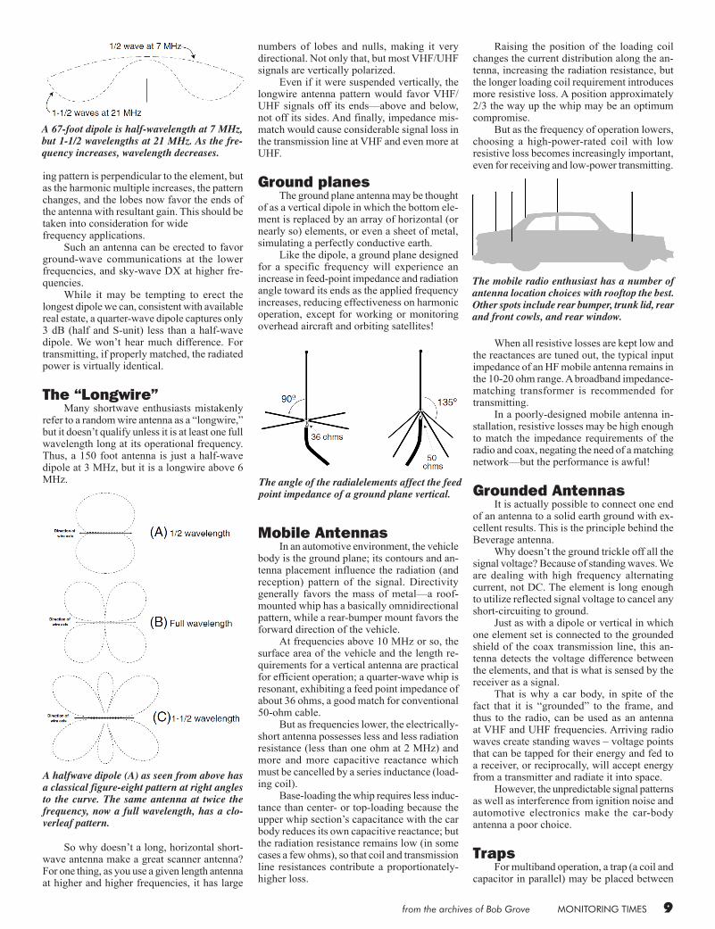
A 67-foot dipole is half-wavelength at 7 MHz, but 1-1/2 wavelengths at 21 MHz. As the fre-quency increases, wavelength decreases.
A halfwave dipole (A) as seen from above has a classical figure-eight pattern at right angles to the curve. The same antenna at twice the frequency, now a full wavelength, has a clo-verleaf pattern.
numbers of lobes and nulls, making it very directional. Not only that, but most VHF/UHF signals are vertically polarized. Even if it were suspended vertically, the longwire antenna pattern would favor VHF/UHF signals off its ends—above and below, not off its sides. And finally, impedance mis-match would cause considerable signal loss in the transmission line at VHF and even more at UHF.
Ground planes The ground plane antenna may be thought of as a vertical dipole in which the bottom ele-ment is replaced by an array of horizontal (or nearly so) elements, or even a sheet of metal, simulating a perfectly conductive earth. Like the dipole, a ground plane designed for a specific frequency will experience an increase in feed-point impedance and radiation angle toward its ends as the applied frequency increases, reducing effectiveness on harmonic operation, except for working or monitoring overhead aircraft and orbiting satellites!
Mobile Antennas In an automotive environment, the vehicle body is the ground plane; its contours and an-tenna placement influence the radiation (and reception) pattern of the signal. Directivity generally favors the mass of metal—a roof-mounted whip has a basically omnidirectional pattern, while a rear-bumper mount favors the forward direction of the vehicle. At frequencies above 10 MHz or so, the surface area of the vehicle and the length re-quirements for a vertical antenna are practical for efficient operation; a quarter-wave whip is resonant, exhibiting a feed point impedance of about 36 ohms, a good match for conventional 50-ohm cable. But as frequencies lower, the electrically-short antenna possesses less and less radiation resistance (less than one ohm at 2 MHz) and more and more capacitive reactance which must be cancelled by a series inductance (load-ing coil). Base-loading the whip requires less induc-tance than center- or top-loading because the upper whip section’s capacitance with the car body reduces its own capacitive reactance; but the radiation resistance remains low (in some cases a few ohms), so that coil and transmission line resistances contribute a proportionately-higher loss.
The angle of the radialelements affect the feed point impedance of a ground plane vertical.
Raising the position of the loading coil changes the current distribution along the an-tenna, increasing the radiation resistance, but the longer loading coil requirement introduces more resistive loss. A position approximately 2/3 the way up the whip may be an optimum compromise. But as the frequency of operation lowers, choosing a high-power-rated coil with low resistive loss becomes increasingly important, even for receiving and low-power transmitting.
When all resistive losses are kept low and the reactances are tuned out, the typical input impedance of an HF mobile antenna remains in the 10-20 ohm range. A broadband impedance-matching transformer is recommended for transmitting. In a poorly-designed mobile antenna in-stallation, resistive losses may be high enough to match the impedance requirements of the radio and coax, negating the need of a matching network—but the performance is awful!
Grounded Antennas It is actually possible to connect one end of an antenna to a solid earth ground with ex-cellent results. This is the principle behind the Beverage antenna. Why doesn’t the ground trickle off all the signal voltage? Because of standing waves. We are dealing with high frequency alternating current, not DC. The element is long enough to utilize reflected signal voltage to cancel any short-circuiting to ground. Just as with a dipole or vertical in which one element set is connected to the grounded shield of the coax transmission line, this an-tenna detects the voltage difference between the elements, and that is what is sensed by the receiver as a signal. That is why a car body, in spite of the fact that it is “grounded” to the frame, and thus to the radio, can be used as an antenna at VHF and UHF frequencies. Arriving radio waves create standing waves – voltage points that can be tapped for their energy and fed to a receiver, or reciprocally, will accept energy from a transmitter and radiate it into space. However, the unpredictable signal patterns as well as interference from ignition noise and automotive electronics make the car-body antenna a poor choice.
Traps For multiband operation, a trap (a coil and capacitor in parallel) may be placed between
The mobile radio enthusiast has a number of antenna location choices with rooftop the best. Other spots include rear bumper, trunk lid, rear and front cowls, and rear window.
10 from the archives of Bob Grove
sections of an antenna to provide automatic selection of appropriate lengths for given fre-quencies. The trap is high Q (sharply tuned) to the resonant frequency of the length closest to the feed point, providing several hundred ohms impedance isolation from the adjoining section(s). At other (non-resonant) frequencies, the coil simply adds slight electrical length be-tween the adjoining elements, all of which now add to the total antenna length. In this manner, a combination of elements and traps allow resonant operation on several bands without the need ofa transmatch. The sections are arranged in frequency order with the highest frequency closest to the feed point.
If a transmatch is available, a trapped antenna is undesirable since it suffers from the traps’ resistive losses, gaps in frequency coverage, more components to fail, and higher cost than a simple dipole.
Active or Passive Antennas?
With one singular exception, all antennas are passive; that is, they have no amplifying electronic circuitry. They simply reflect, re-fract, radiate or conduct the electromagnetic energy which reaches them. The exception is the active (voltage probe or E-field) antenna which consists of a short (a few inches to a few feet) receiving element coupled to a wideband, small-signal amplifier. It is not used for transmitting. While active antennas may have small size and wide bandwidth, and can deliver large signals to the receiver, they have their disadvantages. They are expensive, they re-quire power, they may burn out or degrade in performance from nearby lightning or strong signals, they generate noise and intermodula-tion interference (“intermod”), and they are usually placed close to interference-generating
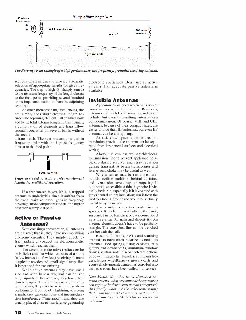
The Beverage is an example of a high performance, low frequency, grounded receiving antenna.
Traps are used to isolate antenna element lengths for multiband operation.
electronic appliances. Don’t use an active antenna if an adequate passive antenna is available.
Invisible Antennas Appearances or deed restrictions some-times require a hidden antenna. Receiving antennas are much less demanding and easier to hide, but even transmitting antennas can be inconspicuous. Of course, VHF and UHF antennas, because of their compact sizes, are easier to hide than HF antennas, but even HF antennas can be unimposing. An attic crawl space is the first recom-mendation provided the antenna can be sepa-rated from large metal surfaces and electrical wiring. Always use low-loss, well-shielded coax transmission line to prevent appliance noise pickup during receive, and stray radiation during transmit. A balun transformer and ferrite-bead choke may be useful as well. Wire antennas may be run along base-boards, ceiling molding, behind curtains, and even under eaves, rugs or carpeting. If outdoors is accessible, a thin, high wire is vir-tually invisible, especially if it is covered with grey (neutral color) insulation; run it from the roof to a tree. A ground rod would be virtually invisible by its nature. A wire antenna in a tree is also incon-spicuous. It can be run vertically up the trunk, suspended in the branches, or even constructed as a wire array for gain and directivity. An antenna element doesn’t have to be perfectly straight. The coax feed line can be trenched just beneath the soil. Resourceful hams, SWLs and scanning enthusiasts have often resorted to make-do antennas. Bed springs, filing cabinets, rain gutters and downspouts, aluminum window frames, curtain rods, disconnected telephone or power lines, metal flagpoles, aluminum lad-ders, fences, wheelbarrows, grocery carts, and even vehicle-mounted antennas coax-fed into the radio room have been called into service!
Next Month: Now that we’ve discussed an-tenna systems, what recommended accessories can improve both transmission and reception? And finally, what are the take-home points that mean the most? Don’t miss next month’s conclusion to this MT exclusive series on antennas!

from the archives of Bob Grove MONITORING TIMES 11
I n the four previous issues we’ve covered just about every aspect of antennas and their permutations. In this final chapter
we’ll discuss the best ways to connect them to radio equipment, and review the most important facts to remember. At audio frequencies, any kind of connec-tor will work as long as it can handle the voltage and current. But at radio frequencies, connector design is critical. Audio connectors, such as RCA phono connectors and earphone plugs, become increasingly deficient with frequency and have no specific impedance characteristics. They are usable up to about 30 MHz for receiv-ing purposes. Motorola connectors, developed for AM car radios, were grandfathered into VHF use when FM coverage was added to those radios. Early VHF converters needed Motorola con-nectors in order to interface with the car radios; then mobile scanners adopted them since the car antenna could be called into limited service for local scanner reception. Marginal in per-formance at VHF/UHF frequencies, Motorola plugs have been abandoned by scanner manu-facturers in favor of infinitely superior BNC connectors. The BNC was named for its configura-tion and inventors – it is a (B)ayonet design by (N)eill and (C)oncelman and is excellent for applications through at least 1,000 MHz (1 GHz). Neill also contributed his initial to the N connector, developed during World War II for military UHF communications. It is an excellent waterproof choice through at least 2 GHz, but harder to assemble since it is de-signed for large RG-8/U and R-213/U cables. Concelman’s initial adorns the less popular C connector of World War II.
The PL-259 (the so-called “UHF” con-nector), developed during the 1930s, is still a favorite for HF ham and CB transceivers as well as shortwave receivers. It works well up to at least 50-100 MHz. Low-cost, TV-type F connectors work extremely well through at least 1 GHz, but they require solid-center-wire cable, and adaptors are always needed to interconnect communica-tions equipment and accessories. Some imported nickel-plated connectors are poorly made; their loose fittings and out-of-tolerance thread pitches can add noise, intermit-tent performance, signal loss, and electrolytic corrosion to the system. On the other hand, a lab test at Grove Enterprises showed only a fraction of a dB loss at 1 GHz from five differ-ent, imported, nickel-plated adaptors cascaded in series. But, to be safe, it’s always better to choose a branded, silver (or gold) plated connector or adaptor if available. Better yet, use a cable with the correct connectors instead of adaptors.
Preamplifiers A preamplifier (“pre-amp” or “signal booster”) is simply a small-signal amplifier placed between the antenna and receiver. When integrated with a small receiving antenna, the combination is called an active antenna (previ-ously discussed). A preamplifier connected to a poorly-located antenna will not perform as well as a well-placed, larger “passive” (unamplified) antenna, but it may be the only alternative when the better antenna is not practical. If a shortwave receiving antenna is at least 20 feet long and in the clear, a preamplifier is probably
unnecessary. A preamp must have a lower noise figure (self-generated “hiss”) than the receiver, or the only thing it accomplishes is increasing both signal and noise, just as if you had merely turned up the receiver’s volume control. It must have wide dynamic range – the ability to amplify weak and strong signals equally without becoming overloaded and thus generating spurious signal products, known as intermodulation (intermod), which interfere with normal reception. At VHF and especially UHF frequencies and above, where transmission line losses may become significant, a preamplifier mounted at the antenna will boost signals above the loss characteristic of the line. Still, the preamp is vulnerable to all the problems described above. Even when working perfectly, a preamp can cause the receiver to overload and generate intermod of its own, desensitizing it to weak signals, aggravating images, or even damaging its delicate RF amplifier circuitry. Use it as a last resort.
Splitters and combiners A splitter is essentially a broadband RF transformer which allows one signal source to be equally divided into two or more paths; this allows, for example, several receivers to operate from one antenna. Since a typical two-way splitter is an RF voltage divider, each output will be reduced by 3 dB, half the original power level. Connected in reverse, a splitter becomes
All about Antennas Part 5: Accessories, Connectors and Adaptors
By Bob Grove W8JHD
The most common antenna connectors and their maximum recommended frequencies.
A preamplifier should only be used in excep-tionally weak signal areas.
12 from the archives of Bob Grove
a combiner, allowing two signal sources to add commonly. This allows, for example, two separate-frequency antennas to be used simul-taneously with one receiver. But, if the two antennas have a similar frequency response, they can produce destruc-tive interference (signal canceling) from certain directions, while providing 3 dB overall gain in other directions. Basically, they comprise a directional array – a “beam” antenna. TV splitters marked “V/U” or “VHF/UHF” or “54-890 MHz” actually work reason-ably well from the low HF range (typically 3 MHz) up through 1 GHz. While there are transmitter split-ters and combiners, those made for receivers are far more common and less expensive. They will also allow low power – a few watts – to pass without much problem, but higher power levels will heat the fine wind-ing and saturate the small ferrite core, wasting power and even destroying the device.
TV Splitters Splitters used to couple two or more TV sets to a common antenna system are quite suitable for general-purpose receiving installations. Most are marked with their recommended frequency application. Those intended for powering satellite-dish low-noise block down-converters (LNBs), marked 950-1450 MHz, should be avoided for short-wave and scanning, but those marked 5-900 MHz work well from shortwave right up through VHF/UHF scanning. Such splitters are usually DC passive; that is, their windings are electrically interconnected so that voltage may transferred through the splitter to activate an antenna-mount-ed preamplifier or down-converter. However, if you have voltage on the line but don’t want it to get through your DC-passive splitter, and don’t have a DC-blocked splitter available, there are accessory F-to-F
fittings that contain a DC-blocking capacitor that may be attached to the splitter. Some split-ters offer a combination of passive and blocked ports on the same device. Conventional installations which have no DC power requirements on the transmission line work just fine with either DC passive or DC blocked splitters.
Balun transformers The term “balun” (a contraction for “bal-anced to unbalanced”) is a wideband RF trans-former that allows an unbalanced transmission line (coax) to be used with a balanced antenna (dipole or beam). Many transmatches include balun circuitry. Balun transformers may incorporate a step-up ratio (typically 4:1) to allow low-impedance coax to correctly match high-impedance antenna feed points, or a simple 1:1 ratio to connect coax (unbalanced) to a balanced feed point. Instead of a 1:1 balun transformer, a ferrite bead RF choke at the antenna-coax feed point will reduce RF on the feed line by absorbing unbalanced power. Like splitters, VHF/UHF TV balun trans-formers can be used with VHF/UHF scanners, shortwave receivers down to about 3 MHz, and even for low-power (a few watts) transmitters. If a balun transformer is connected be-tween the feed line and antenna, a transmatch will still resonate the entire system – balun,
antenna, feed line, tuner, and interactive environment (tower, nearby wires, trees, rain gutters, etc.). But the tuner does not change the anten-na’s natural feed point impedance; if there was a mismatch be-tween it and the balun or feed line before the tune-up, it will remain even after the tuner is adjusted to resonance and shows a 1:1 match. A balun works properly only with resistive (non-reactive) loads; system reactances can cause impedance transformation ratios different from what was intended. Therefore, it is not a good idea to use a balun over a wide frequency range on a narrowband antenna. Baluns also add losses, due to wire resistance and possible core saturation during transmit.
Attenuators It may seem self-defeating to make re-ceived signals weaker, but under some condi-tions it is advisable. For example, if you live near several broadcast transmitters, or a high-powered paging transmitter, or if most signals in your area are quite strong, they may be too hot for your receiver or scanner to handle.
Receivers may “come apart” under these conditions, gen-erating spurious signals (intermod) or even desensitizing, making weak-signal reception virtually impossible. If your outdoor antenna causes either of these symptoms, an attenuator may be the prescription; some receivers and scanners have them built in. But if an attenuator is likely to make desirable weak signals unreadable, try a filter.
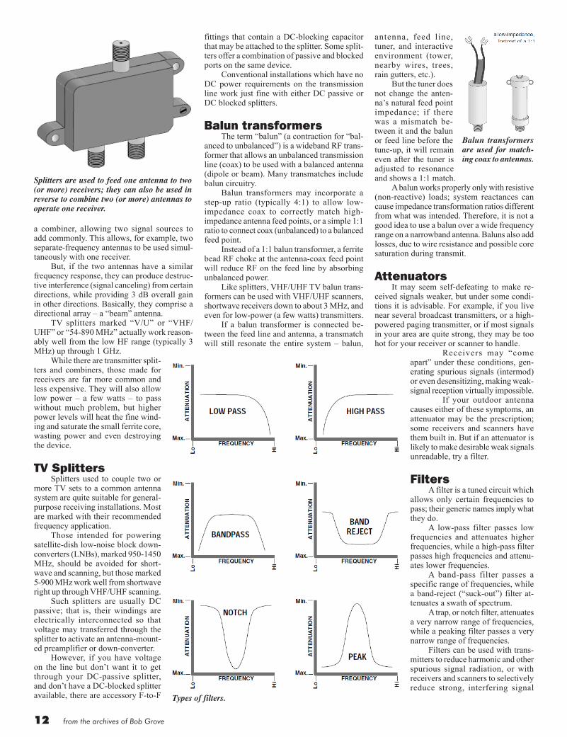
Filters A filter is a tuned circuit which allows only certain frequencies to pass; their generic names imply what they do. A low-pass filter passes low frequencies and attenuates higher frequencies, while a high-pass filter passes high frequencies and attenu-ates lower frequencies. A band-pass filter passes a specific range of frequencies, while a band-reject (“suck-out”) filter at-tenuates a swath of spectrum. A trap, or notch filter, attenuates a very narrow range of frequencies, while a peaking filter passes a very narrow range of frequencies. Filters can be used with trans-mitters to reduce harmonic and other spurious signal radiation, or with receivers and scanners to selectively reduce strong, interfering signal
Balun transformers are used for match-ing coax to antennas.
Types of filters.
Splitters are used to feed one antenna to two (or more) receivers; they can also be used in reverse to combine two (or more) antennas to operate one receiver.

from the archives of Bob Grove MONITORING TIMES 13
frequencies. No filter is perfect in its characteristics; desired signals near the edges of the design range (cutoff frequencies) will also be attenu-ated somewhat. Even at the center of its attenu-ation range, some strong signals may still get through. A credible manufacturer will publish the response curves of his filters to reveal their limitations.
Antenna switches It is often desirable to select among two or more antennas for optimum reception or transmission. For receiving purposes, or even for low power (a few watts) transmitting, TV coax antenna switches work admirably from DC through 1000 MHz. CB-type antenna switches work fine up to about 30MHz, for both receiving and transmitting. For higher power, especially at higher fre-quencies, select a commercial coax switch rated for the frequency range and power required.
Biohazards It has long been known that electromag-netic radiation can produce effects in biological organisms; of particular concern to radio hob-byists is the influence of radio waves on the human body. If we consider the adult as an antenna, it has a natural resonance between 35 MHz (standing, grounded) and 70 MHz (insulated from ground). Body parts, too, are resonant – the head at around 400 MHz (700 MHz for infants). Since the body is a lossy conductor, it dissipates much of the induced energy as heat. But in most cases it is not thermal affects that are of the greatest concern. On-going controversy revolves around whether cancers may be induced by low-level
AC fields from power lines and associated equipment and appliances, as well as transmit-ted radio fields. Virtually all studies suggest that power levels under 100 watts or so into an elevated outdoor antenna are safe. Concern mounts with indoor, attic, mobile, and low-elevation, directional, transmitting antennas. Until all the facts are known, it is best to follow these guidelines:(1) Keep away from antennas and open-wire feed
lines that are transmitting.(2) Elevate well overhead any transmitting an-
tennas, especially directional beams which concentrate their energy.
(3) Operate nearby transmitting antennas (mo-bile, attic, in-room) at low power (nominally no more than 25 watts).
(4) Operate RF power amplifiers with their covers in place.
(5) Hold hand-held transceivers away from your head by using extension mikes.
(6) Stay at least two feet away from power trans-formers.
Take-Home Points – Facts, Not Fiction
As we close this five-part series on antenna systems, here are some of the most important parts to remember:
1. Except for very thin wires, most antennas are efficient radiators. Virtually all losses in an antenna system occur in the feed line.
2. A high standing wave ratio (SWR of 3:1, 6:1, etc.) merely indicates the presence of power reflections on the feed line due to impedance mismatch. If there are no loss-es in the feed line, all reflected transmitter power will be returned to and radiated by the antenna.
For receiving systems, all captured signal power will be returned to the receiver. If there is an impedance mismatch between the receiver and transmission line; how-ever, reflected signal power will return to the antenna where it will be re-radiated back into space
3. Reflected power does not flow back into the transmitter and cause damage or overheating. If damage occurs, it is due to mistuning the amplifier.
4. A low SWR reading only means that the transmitter, feed line and antenna system are impedance-matched; it does not nec-essarily mean that everything is working properly.
Corroded or intermittent connectors, ineffective grounds, lossy cable and other resistive agents can all give a deceptively low SWR. Unless an antenna is broadband by design, a low impedance maintained over a wide frequency range without retun-ing is particularly suspect.
5. Neither an antenna nor the feed line needs to be self-resonant (no inductive or capacitive reactances) to perform properly. Virtually any antenna and its feed line, no matter how reactive, can be brought to resonance by a properly designed trans-match.
6. Using low-loss transmission line, and at frequencies below 30 MHz or so, signals experiencing an SWR of at least 3:1 and perhaps as high as 5:1 will be indistin-
guishable from signals produced by a perfect 1:1 impedance match.
7. Adjusting a transmatch at the radio posi-tion does not alter the reactance or im-pedance of either the antenna or the feed line; it brings the entire mismatched and reactive system into resonance by “conju-gate matching,” introducing reactance-canceling capacitances and inductances of its own, so that the attached receiver or transmitter senses only a resistive load.
8. A large antenna does not radiate more power than a small antenna, nor is more power radiated from a particular configu-ration (dipole, vertical, beam, quad, cage, bowtie, rhombic, loop, etc.). But a large antenna does radiate a more concentrat-ed, directional field than a small antenna, and it captures more signal energy during reception.
9. No transmission line needs to be a specific length if a transmatch is available. Adjust-ing the length of a feed line does not alter the SWR, just the impedance measured at the tuner/feed line connection.
10. High SWR in a coax feed line does not cause RF currents to flow on the outside of the line, nor will the coax radiate. High SWR on an open wire feed line will not cause the feed line to radiate as long as the currents are balanced, wire spacing is small compared to wavelength, and there are no sharp bends.
11. Assuming low-loss feed line, an SWR meter will read the same at the antenna feed point, anywhere on the feed line, and at the transmitter.
12. Raising or lowering an antenna to adjust its feed point impedance has no significant effect on power radiated, only the shape of its elevation pattern. However, raising the pattern between 3 and 20 degrees from the horizon can improve DX communica-tions.
13. A frequency meter or dip oscillator con-nected at the bottom of a feed line cannot measure the resonant frequency of the antenna; it measures only the combined resonance of the antenna plus the feed line.
14. A balun transformer on a transmitting antenna will match impedances correctly only if it is used within its power limitations; excessive current may saturate its core, wastefully heating the balun while giving a deceptive SWR reading.
15. A loading coil on a short antenna doesn’t add missing length, it adds inductive re-actance to cancel the capacitive reactance of the short antenna.
16. A transmatch doesn’t “fool” the transmitter or receiver into “thinking” it is connected to the correct impedance any more than an AC wall adaptor “fools” a radio into “thinking” it is getting 12 volts DC when it is plugged into 120 volts AC. In both cases power and impedance transformations really occur.
RECOMMENDED READING
The ARRL Antenna Book, published by the Ameri-can Radio Relay League, 225 Main St., Newington, CT 06111.
Antennas J.D. Krauss, second edition, 1988; McGraw-Hill Book Co.
Filters are used to remove unwanted signal interferences.
Antenna switches should be chosen care-fully, both to handle high power when used for transmitting, and for low loss when used at VHF/UHF.