Embed Size (px)
Citation preview

OOFFFFIICCEE OOFF TTHHEE SSPPEECCIIAALL IINNSSPPEECCTTOORR GGEENNEERRAALL FFOORR IIRRAAQQ RREECCOONNSSTTRRUUCCTTIIOONN
AAALLL BBBAAASSSRRRAAAHHH OOOIIILLL TTTEEERRRMMMIIINNNAAALLL
BBBAAASSSRRRAAAHHH,,, IIIRRRAAAQQQ
SSSIIIGGGIIIRRR PPPAAA---000666---000888000 AAAPPPRRRIIILLL 222666,,, 222000000777

Report Documentation Page Form ApprovedOMB No. 0704-0188
Public reporting burden for the collection of information is estimated to average 1 hour per response, including the time for reviewing instructions, searching existing data sources, gathering andmaintaining the data needed, and completing and reviewing the collection of information. Send comments regarding this burden estimate or any other aspect of this collection of information,including suggestions for reducing this burden, to Washington Headquarters Services, Directorate for Information Operations and Reports, 1215 Jefferson Davis Highway, Suite 1204, ArlingtonVA 22202-4302. Respondents should be aware that notwithstanding any other provision of law, no person shall be subject to a penalty for failing to comply with a collection of information if itdoes not display a currently valid OMB control number.
1. REPORT DATE 26 APR 2007 2. REPORT TYPE
3. DATES COVERED 00-00-2007 to 00-00-2007
4. TITLE AND SUBTITLE Al Basrah Oil Treatment Basrah, Iraq
5a. CONTRACT NUMBER
5b. GRANT NUMBER
5c. PROGRAM ELEMENT NUMBER
6. AUTHOR(S) 5d. PROJECT NUMBER
5e. TASK NUMBER
5f. WORK UNIT NUMBER
7. PERFORMING ORGANIZATION NAME(S) AND ADDRESS(ES) Office of the Special Inspector General for Iraq Reconstruction,400 ArmyNavy Drive,Arlington,VA,22202
8. PERFORMING ORGANIZATIONREPORT NUMBER
9. SPONSORING/MONITORING AGENCY NAME(S) AND ADDRESS(ES) 10. SPONSOR/MONITOR’S ACRONYM(S)
11. SPONSOR/MONITOR’S REPORT NUMBER(S)
12. DISTRIBUTION/AVAILABILITY STATEMENT Approved for public release; distribution unlimited
13. SUPPLEMENTARY NOTES
14. ABSTRACT
15. SUBJECT TERMS
16. SECURITY CLASSIFICATION OF: 17. LIMITATION OF ABSTRACT Same as
Report (SAR)
18. NUMBEROF PAGES
77
19a. NAME OFRESPONSIBLE PERSON
a. REPORT unclassified
b. ABSTRACT unclassified
c. THIS PAGE unclassified
Standard Form 298 (Rev. 8-98) Prescribed by ANSI Std Z39-18

SPECIAL INSPE CTOR GENE RAL FOR IRAQ RECONSTRUCTION
April 26, 2007
MEMORANDUM FOR DIRECTOR, IRAQ RECONSTRUCTION MANAGEMENT OFFICE
COMMANDING GENERAL, GULF REGION DIVISION, U.S. ARMY CORPS OF ENGINEERS
SUBJECT: Report on the Al Basrah Oil Terminal, Basrah, Iraq (Report Number SIGIR PA-06-090)
The Office of the Special Inspector General for Iraq Reconstruction is providing this report for your information and use. We assessed the design and construction work being performed at the Al Basrah Oil Terminal Basrah, Iraq to determine whether the intended objectives of the four selected Unique Record Identifiers were or will be achieved. This is the first in a series of reports dealing with the objective of increasing Al Basrah Oil Terminal’s loading capacity and enhancing the reliability and safety of terminal operations. This assessment was made to provide you and other interested parties with real-time information on relief and reconstruction projects to enable appropriate action to be taken, if warranted. The assessment team included an engineer/inspector and two auditors/inspectors. The comments received from the Commanding General, Gulf Region Division in response to a draft of this report addressed the recommendations, and the actions taken and planned should address the issues we identified. As a result, comments to this final report are not required. We appreciate the courtesies extended to our staff. If you have any questions please contact Mr. Brian Flynn at [email protected] or at 914-360-0607. For public or congressional queries concerning this report, please contact SIGIR Congressional and Public Affairs at [email protected] or at 703-428-1100.
Stuart W. Bowen, Jr. Inspector General

i
Special Inspector General for Iraq Reconstruction
SIGIR PA-06-080 April 26, 2007
Al Basrah Oil Terminal, Basrah, Iraq
Synopsis Introduction. This project assessment was initiated as part of our continuing assessments of selected sector reconstruction activities for oil. The overall objectives were to determine whether selected sector reconstruction contractors were complying with the terms of their contracts or task orders and to evaluate the effectiveness of the monitoring and controls exercised by administrative quality assurance and contract officers. We conducted this project assessment in accordance with the Quality Standards for Inspections issued by the President’s Council on Integrity and Efficiency. The assessment team included a professional engineer/inspector and two auditors/inspectors. The objective of this project was to increase the Al Basrah Oil Terminal loading capacity to 3 million barrels per day, while enhancing the reliability and safety of terminal operations. The project was funded through the Iraq Relief and Reconstruction Fund and administered by the United States Army Corps of Engineers, Gulf Region South. The United States Army Corps of Engineers, Fort Worth District, Fort Worth, Texas awarded Contract W9126G-04-D-0002, an Indefinite Delivery/Indefinite Quantity, cost plus award fee for the continuing operations of the Iraq oil infrastructure to Parsons Iraqi Joint Venture, Houston, Texas. In order to accomplish these objectives at the Al Basrah Oil Terminal, 15 individual projects were originally identified1, with each project having its own Unique Record Identifier. This is the first in a series of reports dealing with the objective of increasing Al Basrah Oil Terminal’s loading capacity and enhancing the reliability and safety of terminal operations. This report will deal specifically with the following four Unique Record Identifiers:
• Refurbishment of Berths 1 and 2 loading arms • Second repair of Berths 3 and 4 loading arms • Lifeboats and deployment system • Emergency evacuation plan
Since work is currently in-progress at the Al Basrah Oil Terminal by the contractor, an additional site visit may be required to assess the status and quality of the remaining work. Additional reports will follow dealing with the remaining projects, such as metering, fire protection system, and emergency shutdown system. Project Assessment Objectives. The objective of this project assessment was to provide real-time relief and reconstruction project information to interested parties to enable appropriate action, when warranted. Specifically, we determined whether:
1. Project components were adequately designed prior to construction or installation; 2. Construction or rehabilitation met the standards of the design;
1 Of the original fifteen projects, two projects were subsequently cancelled.

ii
3. The contractor’s quality control plan and the United States Government’s quality assurance program were adequate;
4. Project sustainability was addressed; and 5. Project results were consistent with original objectives.
Conclusions. The assessment determined that:
1. Design information submitted for the refurbishment of Berths 1 and 2 loading arms and the repair of Berths 3 and 4 loading arms appeared to be satisfactory for the refurbishment and repair of the loading arms. Parson Iraq Joint Venture’s Project Scope and Status Report for the refurbishment of the Berths 1 and 2 loading arms required the installation of scaffolding on the entire loading arms to carry out the work. Refurbishment included the draining of waste oil, removal of corrosion from the arms and structure, and removing all waste products from the area. To restore the proper working of the mechanism several tasks were required: stripping down the loading arm swivel joints, replacement of all hydraulic seals, hydro testing the risers, function testing the loading arms, and testing all of the hydraulic systems. The repair of the Berths 3 and 4 loading arms required replacing the 24-inch loading arm isolations valves, 24-inch hydraulic power unit valves, and 24-inch local control panel valves.
Design information submitted for the lifeboat deployment system appeared to be incomplete and lacked necessary details. The design package did not properly identify the specific type of life raft needed nor did it establish the exact material composition of the life raft. In addition, Parsons Iraq Joint Venture did not provide the government design drawings with technical details, such as the specification of material used for the proposed life rafts and physical measurements and buoyancy/stability data of the life rafts during rough sea conditions of up to 15 foot waves. This information is critical in order to determine if the life rafts are capable of holding the required number of passengers in a stable floating condition. Finally, the design package did not acknowledge that there is no internationally agreed upon standard that applies to this specific type of offshore crude oil export terminal; therefore, the government representatives responsible for this project needed to thoroughly review the requirements to determine if the recommended life raft was appropriate for an offshore crude oil terminal.
2. Based upon our time limited on-site assessment, the refurbishment of Berths 1 and 2 loading arms and repair of Berths 3 and 4 loading arms appeared to meet the standards of the Scope of Work and design. The refurbishment and repair of the four Berths loading arms improved the arms previously dilapidated and operationally damaged condition. The installation of the lifeboat deployment system had not occurred at the time of our site visit; therefore, we cannot comment on the quality of the construction. However, after our site visit, we were informed of the installation points for the eight life rafts on the Al Basrah Oil Terminal. We are concerned not only in the adequacy of the use of the selected life rafts, but also the strategic location of the life rafts throughout the Al Basrah Oil Terminal. Parsons Iraq Joint Venture’s Safety and Environmental Management Program does not identify the designated muster points for an emergency evacuation from the terminal. Without identifying the pre-designated muster points, we could not determine if the life rafts were installed at the correct locations.

iii
3. The contractor’s quality control plan was sufficiently detailed to effectively guide the contractor’s quality management program. The daily quality control reports documented daily observations of what occurred at the site, weekly overview, construction activities, and critical issues. However, there was a significant lack of detailed site photographs to reinforce the narrative information within the reports. We reviewed 345 daily quality control reports, which included 554 site photographs. Considering the significant amount of work ongoing at the Al Basrah Oil Terminal, we believe more site photographs are needed to reinforce the narrative information within the daily quality control reports. In addition, there was no quality control deficiency log. The government quality assurance program was effective in monitoring the contractor’s quality control program. The United States Army Corps of Engineers, Gulf Region South, which was responsible for the Al Basrah Oil Terminal projects, had dedicated personnel on site at the Al Basrah Oil Terminal during significant construction activities. We found the daily quality assurance reports sufficiently complete, accurate, and timely.
4. The contract and task order adequately addressed sustainability; specifically, requiring the contractor to provide training courses, commissioning, preventive maintenance plan, spare parts, a list of two years of recommended spare parts, and management training. To date, Parsons Iraq Joint Venture has provided a majority of the required training courses. Commissioning, preventive maintenance plan, spare parts, illustrative spare parts, and management training are still pending.
5. The Al Basrah Oil Terminal projects to refurbish and repair the four berths loading arms were consistent with original task order objectives. The task order objective was to increase the loading capacity of the terminal to 3 million barrels per day, and the two projects resulted in the restoration of the Al Basrah Oil Terminal’s design capacity of 4 million barrels per day. One objective of the overall task order was to enhance the reliability and safety of terminal operations. The United States Army Corps of Engineers stated that the Al Basrah Oil Terminal is much safer today than before the task order started; specifically, they believe Fire Protection System project has significantly increased the terminal’s ability to fight fires and lessen the chance of a major terminal fire. However, even with the most sophisticated and advanced systems, the possibility of a major oil fire requiring a full scale terminal evacuation cannot be discounted. We selected three projects which deal with the ability of terminal personnel to safely and adequately account for and evacuate from a potential major terminal fire. The three specific projects we reviewed, the Emergency, Evacuation, and Accountability Program, the Health, Safety, and Environmental Program, and the Lifeboat Deployment System, were not consistent with the task order objective to enhance the safety of terminal operations. Parsons Iraq Joint Venture issued the Safety and Environmental Management Program, which combined the Emergency, Evacuation, and Accountability Program and the Health, Safety, and Environmental Program into one document. The Safety and Environmental Management Program does not address the possibility of a large scale fire on the terminal. Specifically, there is limited discussion of a complete terminal evacuation. In addition, it lacks the basic features, such as identifying the designated muster points for an emergency evacuation, the type of evacuation craft, or the transfer of personnel from the terminal to the designated evacuation craft. Regarding the Lifeboat Deployment System, we have concerns about the

iv
type of life raft, the required number of life rafts, the location of the life rafts, and the lack of training provided to terminal personnel in the use of the life rafts.
Recommendations. We recommend that the Commanding General, Gulf Region Division:
1. Contact the life raft manufacturer directly to determine: a. Whether this particular life raft is appropriate for its intended use as an
evacuation vehicle for an offshore oil platform b. The material of which the life raft canopy is made c. The analysis performed to determine the number of occupants the life raft
will safely hold while maintaining a stable floating condition
2. Require Parsons Iraq Joint Venture to update the Health, Safety and Environmental Management Program to include:
a. Procedures in the event of a major fire b. Points of contact and phone numbers for the Al Faw Terminal to contact in
case of an emergency and the 48-inch crude lines need to be shut off c. Locations for strategic muster points d. Situations requiring a full evacuation of the terminal e. Identity of the evacuation escape vehicles and their locations on the
terminal 3. Provide immediate training to the Al Basrah Oil Terminal operating personnel in
the use of the life rafts. Specifically, request a demonstration video from the manufacturer to use for training terminal personnel
Management Comments. The Gulf Region Division concurred with the recommendations contained in the report. Evaluation of Management Comments. Actions taken during the course of the inspection and planned are fully responsive and should correct potential problems.

Table of Contents
Synopsis i Introduction 1
Objective of the Project Assessment 9 Pre-Site Assessment Background 9
Contract, Task Order and Costs 9 Project Objective 9 Description of Facility (pre-construction) 9 Scope of Work of the Task Order 16 Current Project Design and Specifications 17
Site Assessment
Work Observed 19 Work Completed Since Site Visit 31
Project Quality Management
Contractor’s Quality Control Program 45 Government Quality Assurance Program 45
Project Sustainability 46 Conclusions 48 Recommendations 50 Management Comments 50 Evaluation of Management Comments 50 Appendices
A. Scope and Methodology 51 B. Organization of the Iraqi Ministry of Oil 52 C. Contract, Task Orders, and Modifications 53 D. Scope of Work for Specific URI Project 57 E. Fire Incident at the KAAOT Loading Platform 60 F. Management Comments 64 G. Acronyms 67 H. Report Distribution 68 I. Project Assessment Team Members 70

1
Introduction Iraq has the world’s second largest proven oil reserves. The Iraqi oilfields have proven reserves of approximately 100 billion barrels, with the potential of as high as 200 billion barrels. The Iraqi oilfields account for approximately 16% of all Middle East oil reserves. With the world’s second largest crude oil reserves, the Iraq oil industry is perhaps the most critical link to re-establishing the country as a major economy in the Arabian Gulf. Currently, oil exports provide over 95% of the country’s revenue and are critical to the successful funding of the Iraqi government, since export revenues are used to fund the Iraqi Ministries. Iraq’s oilfields are divided into two distinct production areas: the southern fields and the northern fields (Figure 1). The southern oil fields are dominated by the Rumaila oil fields, with production capacity of approximately 2.4 million barrels per day (bpd); while the northern oil fields are dominated by the Kirkuk fields, with production capacity of approximately 900,000 bpd. There are three major refineries within Iraq – Baiji in the North, Daura in Baghdad, and Basrah in the South. The Rumaila oil fields provide the crude oil for the Basrah refinery, which is then sent to the two gulf oil terminals, the Al Basrah Oil Terminal (ABOT) and the Khor Al Amaya Oil Terminal (KAAOT). The Kirkuk oil fields provide all crude oil for the Baiji refinery, 40 to 45% of the crude oil for the Daura refinery and export of crude oil to Turkey (Figures 2 and 3). Along with providing constant revenue to the Iraqi government, oil and gas fuel are used to operate electrical generation facilities, which in turn support oil, water, telecommunications, and other essential services. In short, Iraq’s entire infrastructure is dependent on the constant and sustainable production of oil. Figure 4 provides an oil system overview.

2
Figure 1. Map of Iraq’s northern and southern oil fields
Kirkuk oilfields 600 wells
Rumaila oilfields 1000 wells

3
Figure 2. Flow of Iraqi crude oil pipelines to the refineries to the export terminals (ABOT and KAAOT)
Figure 3. Enlarged section of the Basrah refinery area and export terminals ABOT and KAAOT
Basrah
Kuwait
Iran
ABOT
KAAOT

4
Figure 4. Oil system overview for Iraq from source to export

5
Iraqi Oil Production History Oil was discovered in Iraq in 1903. Only 17 of 80 oil fields have been developed, with the most significant fields being Kirkuk in the north and Rumaila in the south. The giant Kirkuk fields were discovered in 1927; while the Rumaila fields were discovered in the 1970s. There has been virtually no exploration for many years, which suggests that Iraq may have significantly more oil than originally estimated. Iraq’s peak production occurred in December 1979 at 3.7 million bpd, and then just prior to its invasion of Kuwait in July 1990 at 3.5 million bpd. However, after the invasion of Kuwait, exports were halted due to the international boycott. From 1991–1996, when production crashed due to the war, Iraqi oil output increased slowly, to approximately 600,000 bpd. Iraqi’s southern oil industry was decimated in the first Gulf War, with production capacity falling to approximately 75,000 bpd in mid-1991. The first Gulf War resulted in the destruction of gathering centers and compression/degassing stations at Rumaila, storage facilities, the 1.6 million bpd ABOT export terminal, and pumping stations along the 1.4 million bpd (pre-war capacity) Iraqi Strategic (North-South) Pipeline. With Iraq’s acceptance in late 1996 to U.N. Resolution 986, which allowed limited Iraqi oil exports in exchange for food and other supplies (“Oil for Food”), the country’s oil output began increasing more rapidly, from approximately 1.2 million in 1997 to approximately 2.6 million bpd in January 2003. Although Iraq was able to increase oil production in the 1990s, this was accomplished primarily through the use of improvised maintenance techniques, scavenged spare parts, and the cannibalization of equipment, especially at the country’s refineries. Organization of the Iraqi Ministry of Oil The Iraqi Ministry of Oil (MOO) oversees the nationalized oil industry though the Iraq National Oil Company (INOC). The charter of the MOO is to be the “premier oil supplier to the world through effective exploration, production, and supply.” The MOO functional areas are divided into the following: upstream, downstream, and distribution and marketing (Appendix B). Autonomous companies under the INOC include the following: State Company for Oil Projects – design and engineering of upstream and downstream projects; Oil Exploration Company – exploration; North Oil Company and South Oil Company (SOC) – upstream activities in northern/central and southern Iraq, respectively; State Organization for Oil Marketing – crude oil sales and OPEC relations; and Iraqi Oil Tankers Company. Upstream is responsible for oil production, which consists of exploration, drilling, and moving crude. Downstream is responsible for oil refinement, which consists of the production of refined products, gas bottling, distribution, and pipeline repair. Distribution and marketing is responsible for the sale and purchase of oil, specifically contracts to individual companies for buying crude and fuel oil. Task Force - Restore Iraqi Oil The United States Army Corps of Engineers (USACE) was assigned the responsibility to repair and restore the oil infrastructure by the Department of Defense. The mission, called Task Force – Restore Iraqi Oil (TF-RIO) was assigned to the USACE
6
Southwestern Division, located in Dallas, TX. TF-RIO was constituted prior to the beginning of Operation Iraqi Freedom. The mission included the following:
• Extinguishing oil well fires following hostilities • Safe shut down of oil facilities during the initial stages of the war • Provide environmental restoration for both marine and land-based oil spills • Repair and restoration of facilities damaged as a result of the war • Assist the Oil Ministry in the restart, operation, maintenance, and distribution of
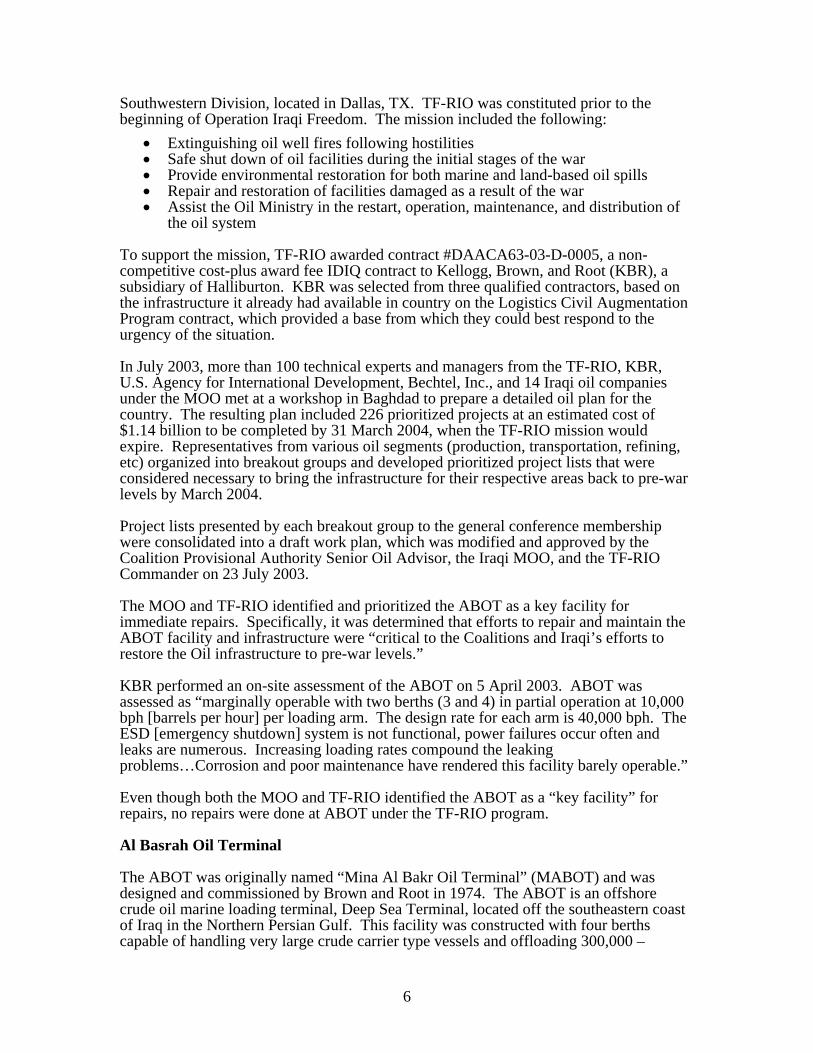
the oil system To support the mission, TF-RIO awarded contract #DAACA63-03-D-0005, a non-competitive cost-plus award fee IDIQ contract to Kellogg, Brown, and Root (KBR), a subsidiary of Halliburton. KBR was selected from three qualified contractors, based on the infrastructure it already had available in country on the Logistics Civil Augmentation Program contract, which provided a base from which they could best respond to the urgency of the situation. In July 2003, more than 100 technical experts and managers from the TF-RIO, KBR, U.S. Agency for International Development, Bechtel, Inc., and 14 Iraqi oil companies under the MOO met at a workshop in Baghdad to prepare a detailed oil plan for the country. The resulting plan included 226 prioritized projects at an estimated cost of $1.14 billion to be completed by 31 March 2004, when the TF-RIO mission would expire. Representatives from various oil segments (production, transportation, refining, etc) organized into breakout groups and developed prioritized project lists that were considered necessary to bring the infrastructure for their respective areas back to pre-war levels by March 2004. Project lists presented by each breakout group to the general conference membership were consolidated into a draft work plan, which was modified and approved by the Coalition Provisional Authority Senior Oil Advisor, the Iraqi MOO, and the TF-RIO Commander on 23 July 2003. The MOO and TF-RIO identified and prioritized the ABOT as a key facility for immediate repairs. Specifically, it was determined that efforts to repair and maintain the ABOT facility and infrastructure were “critical to the Coalitions and Iraqi’s efforts to restore the Oil infrastructure to pre-war levels.” KBR performed an on-site assessment of the ABOT on 5 April 2003. ABOT was assessed as “marginally operable with two berths (3 and 4) in partial operation at 10,000 bph [barrels per hour] per loading arm. The design rate for each arm is 40,000 bph. The ESD [emergency shutdown] system is not functional, power failures occur often and leaks are numerous. Increasing loading rates compound the leaking problems…Corrosion and poor maintenance have rendered this facility barely operable.” Even though both the MOO and TF-RIO identified the ABOT as a “key facility” for repairs, no repairs were done at ABOT under the TF-RIO program. Al Basrah Oil Terminal The ABOT was originally named “Mina Al Bakr Oil Terminal” (MABOT) and was designed and commissioned by Brown and Root in 1974. The ABOT is an offshore crude oil marine loading terminal, Deep Sea Terminal, located off the southeastern coast of Iraq in the Northern Persian Gulf. This facility was constructed with four berths capable of handling very large crude carrier type vessels and offloading 300,000 –
7
400,000 bpd per each berth (Site Photo 1). The ABOT suffered significant damage during the 1980-1988 Iran-Iraq War; however, it remained in service until 1989, when Brown and Root attempted to refurbish it in 1990 (after the conclusion of the Iraq-Iran War). Work stopped when Iraq invaded Kuwait in 1990 and the facility was inflicted with further damage during the Gulf War. In addition, the platform was operated under the Oil for Food program for several years thereafter with minimal maintenance. The terminal was later renamed ABOT. The ABOT is one of Iraq’s two main export outlets – the other outlet being the KAAOT. Crude oil produced for export from the southern Iraqi oilfields is carried through a 48-inch pipeline to the southern most tip of the Al Faw Peninsula, then undersea approximately 50 kilometers (km) south to the ABOT platform (Figure 5).
Site Photo 1. Aerial view of ABOT’s four berths (Photo courtesy of USACE)

8
Figure 5. Overview of Iraqi southern distribution system from the oil fields to Al Faw to ABOT
Two 48” pipelines

9
Objective of the Project Assessment The objective of this project assessment was to provide real-time relief and reconstruction project information to interested parties to enable appropriate action, when warranted. Specifically, we determined whether:
1. Project components were adequately designed prior to construction or installation; 2. Construction or rehabilitation met the standards of the design; 3. The contractor’s quality control (QC) plan and the U.S. Government’s quality
assurance (QA) program were adequate; 4. Project sustainability was addressed ; and 5. Project results were consistent with original objectives.
Pre-Site Assessment Background
Contract, Task Order, and Costs The ABOT project was completed under Contract W9126G-04-D-0002, awarded on 16 January 2004, as an Indefinite Delivery/ Indefinite Quantity, cost plus award fee for the continuing operations of the Iraq oil infrastructure. The contract was between the USACE, Fort Worth District, Fort Worth, Texas and Parsons Iraq Joint Venture (PIJV), Houston, Texas. The guaranteed minimum of Contract W9126G-04-D-0002 is $500,000 (Base Period) and the estimated not-to-exceed amount of $800,000,000. There were five modifications to the initial contract; however, only Modification P00005 to the initial contract was located. There is one task order (TO) associated with this particular project – TO 0016. TO 0016 currently contains 23 modifications. For a detailed list of the contract, TO, and modifications, see Appendix C. Project Objective The overall objective of TO 0016 was to increase the ABOT loading capacity to 3 million bpd, while enhancing the reliability and safety of terminal operations. The existing facility normally operates at a loading capacity of approximately 1.2 million bpd.
Description of the Facility (pre-construction) The description of the facility was based on information obtained from the contract, the project file, the Gulf Region Division (GRD)/Project and Contracting Office (PCO) personnel, PIJV personnel, and the ABOT personnel. The ABOT is situated in the Persian Gulf off the southeastern coast of Iraq (Figure 6). The ABOT facility consists of a series of steel piled structures, with steel decks, interconnected by walkways (Site Photo 2). The terminal facility is approximately 1.6 kilometers long and is located in a water depth of approximately 36 meters (m) due to the large size of the tankers hauling oil (Site Photo 3).

10
Figure 6. ABOT, located in the Persian Gulf near the port of Umm Qasr
Umm Qasr

11
Site Photo 2. Aerial photo of ABOT platform (Photo courtesy of USACE)
Site Photo 3. Dimensions of ABOT
1.6 km in length
36 meters deep
Helipad
Berth 4
Berth 1
Berth 3 Platform B
MD6
Platform A
Living Quarters
Berth 2

12
The crude oil loading system involves the direct transfer of crude oil from the pumping station at the Al-Faw onshore terminal, located on the Al Faw peninsula, to the two loading platforms of the ABOT, via two 48-inch diameter by 50 km long sub-sea export pipelines (Figure 7 and Site Photos 4 and 5). The Al Faw Terminal serves as oil storage and pumping stations for the deep sea terminals. The facility lies in an east-west orientation. It has two rectangular main platforms, A and B, with a berth of the north and south end of each platform. These platforms are steel piled structures with steel decks. Each berth is fitted with three articulated loading arms, 24-inches in diameter. There is an accommodation space/living quarters for platform personnel at the extreme west end of the terminal facility and a helipad at the extreme east end. The helipad is currently not in use due to the presence of the staged equipment there. There are two utilities platforms, mooring dolphin (MD) 2 and MD6. MD2 is located between the accommodation living quarters and platform A; MD6 is located between platform A and platform B. There are nine further MD designated platforms, which act as mooring dolphins and as interconnecting bridge support structures. The ABOT was originally designed to have a maximum design loading rate of 4 million bpd. The “as new” tanker loading capacity of the terminal allows the concurrent loading of two fully loaded tankers up to 350,000 Deadweight Tons (DWT) and two 85,000 DWT or smaller tankers (Site Photo 6). The tankers currently being loaded at ABOT have a 2 million barrel capacity. According to GRD Oil representatives, the loading time is approximately 60 hours per tanker. The two connected, independent crude loading platforms designated as platform A and platform B, respectively, deliver crude oil fluids via four independent berths (platform A – Berths 1 and 2, platform B – Berths 3 and 4) to Very Large Crude Carrier tankers. The 48-inch pipelines go first to platform A where they rise to the platform deck and then back to the ocean floor and on to platform B. At each platform, they are connected to a valve manifold system that can deliver crude oil to either of the two tanker loading berths on each platform. The ABOT was operating at reduced production rates because of the dilapidated condition of the crude oil loading arms and the missing and damaged ancillary equipment. The initial assessment of the loading arms on Berths 1 and 2 found severe rust, corrosion, and oil leakage (Site Photos 7, 8, and 9). According to PIJV’s site visit report, for platform B, Berths 3 and 4 loading arms were refurbished in 2003. However, they suffered operational damage and developed hydraulic leaks, which required repairs. Limitations to increase production rates Even though the intent of TO 0016 was to increase the terminal loading capacity to 3 million bpd (considered the “pre-war” rate), the work performed at ABOT will not automatically increase production rates significantly. According to GRD Oil and IRMO Oil representatives, the Iraqi oil infrastructure is in desperate need of upgrades and improvements and until the entire infrastructure is dramatically improved, drastic increases in production rates will not occur. For example, a limiting factor for the loading rate is the current distressed condition of the 48-inch sub-sea pipelines. Due to the large number of leaks and temporary repairs the operating pressure of the pipeline is significantly reduced therefore “slowing” down

13
the delivery of the crude oil to the terminal. There was no work performed or planned for the pipeline under this contract.
Figure 7. Illustration of the crude oil loading system from the Al Faw storage terminal to ABOT through two 48-inch lines
Site Photo 4. Two 48-inch incoming sea lines
Site Photo 5. Close-up view of Site Photo 4

14
Site Photo 6. Four tankers berthed at ABOT (Photo courtesy of USACE)

15
Site Photo 7. Location of Berths 1 and 2 loading arms (Photo courtesy of USACE)
Site Photo 8. Previous condition of Berth 1 loading arm Site Photo 9. Previous condition of Berth 2 loading arm
Berth 1 loading arms
Berth 2 loading arms
Severe rust, corrosion, and oil leakage

16
Scope of Work of the Contract The objective of TO 0016 was to increase the ABOT loading capacity to 3 million bpd, while enhancing the reliability and safety of terminal operations. Specifically, TO 0016’s Scope of Work (SOW) required the contractor to:
URI2 Number Title of Project3 18031 Berths 1 and 2 Loading Arm Refurbishment 18033 ABOT Pipeline Repairs 18034 ABOT Emergency Shutdown System 18035 Metering 18037 ABOT Power Generation and Cable 18038 ABOT Fire Protection System 18039 ABOT Grating and Handrail Repair 18157 Terminal Oil Spill Containment 20782 ABOT Marine Works and Life Support 22670 On the Job Training 22671 Emergency Evacuation Plan 22672 Health, Safety, and Environmental Program 22673 Lifeboats and Deployment System 22674 Second Repair Berth 3 and 4 Loading Arms 22675 Hydraulic Bridge System
The ABOT projects were divided into two phases. Phase 1 work was to be from 3 October 2005 through 31 March 2006; while Phase 2 was to be from to 1 April 2006 through 31 December 2006. Phase 1 work included the following:
• Design, engineering, and procurement for all projects for all phases, including metering streams to be installed during Phase 2
• Repair and refurbish Berths 1, 2, 3, and 4 loading arms • Repair of the hydraulic systems for all loading arms, 24-inch valves, and 48-inch
valves, • Repair of hydraulic bridging systems • Complete development of emergency evacuation program • Complete development of health, safety, and environmental program • Operation, refurbishment, and maintenance training
Phase 2 work included the following:
• Completion of design, engineering, and procurement for all projects • Installation of a complete emergency shutdown system, including containerized
control room for each platform; installation of separate flow metering computer system, and separate ESD/F&G system for each platform
• Refurbishment and installation of 2 generators on MD 6 and single auxiliary building for platform A
• Completion of fire protection system, including foam skids • Installation of 2 new turbine meter streams and the connection of 3 existing meter
streams on platform A, including instrumentation, flow control valves, and motorized valves
2 URI is the acronym for Unique Record Identifier 3 For a complete description of each URI Project, see Appendix D

17
• Replacement of positive displacement meter streams on platform B with the same turbine meter streams of platform A
• Installation of 2 new compact prover loops for platforms A and B • Complete life raft installation • Pre-commissioning and commissioning all operation systems • Operations, maintenance, and sustainment training on essential equipment for
recommended terminal staff Current Project Design and Specifications According to the TO SOW the “contractor will develop and provide material and services in accordance with this SOW Section 2 and of the Basic Contract. Unless indicated otherwise, performance standards will be in accordance with applicable and current industry recognized, international codes and standards for the type of work being performed and the Contract. A list of these standards shall be provided by the Contractor prior to the execution of the task or tasks associated with this SOW. The Government retains the right to approve/disapprove proposed standards, as well as to specify its own standards as required.” For the refurbishment of the Berths 1 and 2 loading arms, PIJV’s Project Scope and Status Report (PSSR), dated 3 May 2005, required the installation of scaffolding on the entire loading arms, chemical cleaning of the waste oil and corrosion from the arms and structure and removing all waste product from the area, stripping down the loading arm swivel joints, inspecting the base riser, style 40, style 50, style 80 top insulation joint and style 80 swivel joint down, and replacing joints regardless of condition. Also included is the replacement of all hydraulic seals, including face seals, ball trunnions, cylinders, flange seals, and all tubing and hoses, hydro testing the risers, function testing the loading arms, and testing all of the hydraulic systems. Since Berths 3 and 4 loading arms were refurbished in 2003, the necessary repairs to the loading arms were replacing the following:
• 24-inch loading arm isolation valves • 24-inch hydraulic power unit valves • 24-inch local control panel valves
Based upon our review of the design information submitted for the refurbishment of Berths 1 and 2 loading arms and the repair of Berths 3 and 4 loading arms, it appeared to be satisfactory for the contractor to refurbish and repair the loading arms. For the Lifeboat Deployment System project, in November 2005, PIJV listed a major fire on ABOT as the need to upgrade ABOT’s existing lifeboats. PIJV initially stated a minimum of five motorized lifeboats and ten life rafts were needed to meet the minimum American Bureau of Shipping (ABS) guidelines. The requirement for motorized lifeboats was later de-scoped and instead the project consisted of 15 life rafts, each capable of holding 16 people. In March 2006, PIJV submitted a PSSR entitled “Engineering Standard Equipment Specification – Life Rafts.” In this PSSR, PIJV did not specify the exact material composition of the life rafts; instead the PSSR stated that “every inflatable survival device shall be constructed, tested, inspected and serviced in compliance with SOLAS [Safety of Live at Sea] and the requirements of the Life Saving Equipment Regulations.” The PSSR did not provide the government design drawings with technical details, such as the specification of material used for the proposed life rafts and physical measurements and buoyancy/stability data of the life rafts.

18
PIJV referred to the life raft as an “inflatable survival device” and further stated that “all materials and components used in the construction and repair of the inflatable survival appliances shall be of good quality and suitable for the intended purpose.” However, according to PIJV’s PSSR, the requirement was for “emergency and/or fast rescue boats to be placed on the terminal platform for personnel in the event of an emergency.” The original emergency, as stated by PIJV in November 2005, was a “major fire,” which would require the ability to quickly leave the area of the fire through the use of the life rafts. In order to quickly leave an area, each life raft would need a motor; however, the PSSR does not address this issue. GRD Oil representatives contend that ABOT’s current safety posture is “remarkably improved;” however, offshore oil drilling and loading terminals are inherently dangerous places to work and live because of the very high probability of an explosion and/or fire due to the flammable nature of oil and gas. Even under ideal circumstances (i.e. the implementation of every health and safety rule/law/guideline and using the most up to date technological equipment), safety remains a paramount concern for the owners and operators. Disasters have occurred on newer oil platforms located throughout the world equipped with state of the art technology, communications, and life safety equipment. Since the worst case scenario would be a major oil fire not only on the ABOT but more than likely spilling into the Persian Gulf, we believe the minimum requirement needed to be an enclosed capsule that is fire retardant. The PSSR required a “canopy to protect the occupants from exposure;” however, this requirement does not address the probability of oil on the ocean surface being ablaze and any openings on the life raft would result in significant injuries, if not deaths. With this PSSR, the original requirement of motorized lifeboats was changed to life rafts and the standard switched from ABS guidelines to SOLAS. However, according to GRD Oil representatives, there is no internationally agreed upon standard that applies to this specific type of offshore crude oil export terminal. Specifically, GRD Oil stated that the SOLAS is the “defacto standard for many marine applications, including offshore platforms.” Based upon our review of the design information submitted for the lifeboat deployment system, it appeared to be incomplete and lacked necessary details. The design package did not properly identify the specific type of life raft needed nor did it establish the exact material composition of the life raft. In addition, PIJV did not provide the government design drawings with technical details, such as the specification of material used for the proposed life rafts and physical measurements and buoyancy/stability data of the life rafts during rough sea conditions of up to 15 foot waves. This information is critical in order to determine if the life rafts are capable of holding the required number of passengers in a stable floating condition. Finally, the design package did not acknowledge that there is no internationally agreed upon standard that applies to this specific type of offshore crude oil export terminal; therefore, the government representatives responsible for this project needed to thoroughly review the requirements to determine if the recommended life raft was appropriate for an offshore crude oil terminal. Further, according to the SOW, the “Government retains the right to approve/disapprove proposed standards, as well as to specify its own standards as required.” According to GRD representatives, since the cost of the life rafts was below the $250,000 threshold, PIJV “had no requirement to seek the Government consent to place an order for the life rafts.” However, PIJV submitted its PSSR entitled “Engineering Standard Equipment Specification” for life rafts on 28 March 2006. In March 2007, the government and its technical experts, Foster Wheeler, stated they did not review the PIJV PSSR submittal.

19
Copies of deliverables, such as (but not limited to) plans, schedules, data, software, etc, will be provided to PCO Oil and/or designated representatives in accordance with Section C of the basic contract. Additional submittals are required in accordance with this Statement of Work. Unless otherwise specified in the document matrix or elsewhere in this task order, deliverables shall consist of a minimum of one (1) electronic copy and three (3) paper copies. Prior to the start of any activity associated with the implementation of this SOW, a quality system shall be developed and submitted for approval to PCO Oil (send information copy to the GRD Area Engineer - Oil) in accordance with Section E of the basic contract. Inspection by the Contracting Officer or other government representatives does not relieve the contractor of the overall responsibility for the quality of associated work. Site Assessment On 19 November 2006, we performed a limited on-site assessment of the ABOT. Due to security concerns, we performed an expedited assessment. The time allotted for the entire assessment was approximately one hour; therefore, a complete review of all project work completed and in progress was not possible. On the day of the site visit, work was in progress by PIJV and its subcontractor. Due to the severe time limitation on ABOT, we were able to visually inspect only the loading arms and life boat project. Work Observed Loading Arms URIs 18031 and 22674 Twelve 24-inch diameter loading arms were installed new when ABOT was constructed in 1975. Each loading berth has three identical 24-inch diameter by 80 foot long LUCEAT DCMA loading arms (Figure 8 and Site Photo 10). These 12 loading arms have hydraulically powered inboard and outboard arms. Each loading arm is comprised of a vertical riser base assembly supporting the arm, an inboard section, an outboard section, a counter-weight and pantograph system for balancing the arm in all positions, a 24-inch selector valve, a set of hydraulic cylinders to control movement, and a hydraulically operated coupling. The couplings are fitted with adapters to allow coupling to tanker manifold flanges ranging in size from 16 to 24 inches. The hydraulic cylinders are attached to the loading arms to control their movement. The three main movements of the arms are the following:
1. Slewing (rotation in the horizontal plane) of the complete arm 2. Raising and lowering of the inboard section of the arm 3. Raising or lowering of the outboard section
Berths 1 and 2 loading arms have not been serviced since they were commissioned. According to PIJV’s initial site survey report, dated 8 April 2005, the loading arms and their ancillary equipment on platform A were inspected and found to be in urgent need of repair/replacement. The six 24-inch diameter loading arms on Berths 1 and 2 required refurbishing and a full mechanical inspection and overhaul. In addition, the loading arm hydraulic units and local control panels required complete overhaul and refurbishment.

20
Figure 8. Schematic view of the 12 ABOT loading arms
Site Photo 10. View of 48” lines, meter skid, and 24” loading arms
12 LUCEAT DCMA loading arms, each 24” in diameter

21
During our site visit to ABOT, we identified the 12 loading arms, which were hydraulically powered and remotely controlled to engage and disengage to the tanker. We observed the recently refurbished loading arms (Site Photos 11 and 12). The refurbished loading arms are under the operational control of the SOC, who are responsible for its usage and maintenance. This is of crucial importance for sustaining the current level of loading volume. At the time of our site visit, three large tankers were docked at ABOT; however, only two tankers were being loaded with crude oil (Site Photos 13, 14, and 15). The loading arms for Berths 3 and 4 were connected to the tankers, performing its intended function (Site Photos 16, 17, and 18). As a result, Berths 3 and 4 were being used to load crude oil onto the tankers via the repaired loading arms. However, it is important to note that because of time and security constraints we did not witness the fully automated and remotely initiated sequence of movements of the loading arm system making connection to the tanker. The function of an automated operating sequence initiated from a local control room on a berth is the following – after the loading arm makes a positive connection to the tanker and oil begins to flow through the pipes of the loading arms, sensors can detect a leak or other malfunction within the loading arm system and stop the flow of oil.
Site Photo 11. Loading arms in stand-by position Site Photo 12. Loading arm connector for the tanker

22
Site Photo 13. Three tankers docked at ABOT on 19 November 2006 – two tankers receiving oil
Site Photo 14. Two tankers receiving oil Site Photo 15. Tanker docked but not receiving oil
3 large tankers docked at ABOT on 19 November 2006
2 tankers receiving crude oil

23
Site Photo 16. Two loading arms engaged to the receiving tanker
Site Photo 17. Enlarged view of one engaged loading arm Site Photo 18. Connection of loading arm to receiving tanker
Tanker receiving crude oil via two loading arms

24
All actively engaged arms delivering oil to the tankers did not exhibit any malfunction during our visit. Based upon our observation, the refurbishment of Berths 1 and 2 loading arms and repair of Berths 3 and 4 loading arms appeared to improve the arms previously dilapidated and operationally damaged condition. As a result, for the first time in many years, all four berths are in operation. In addition, according to GRD representatives, this has significantly improved loading efficiency by allowing four tankers to berth at the same time. With regards to the original intent of the TO to increase the ABOT loading capacity to 3 million bpd, GRD representatives stated the following:
“However, although 4 tankers can now berth [simultaneously] only 2 tankers can load at any one time. Thus although the loading capacity has been fully restored there will not be a notable increase in exports until the onshore pumps, storage and pipelines are re-built…Therefore, although ABOTs 4.0 million barrel per day design capacity has been restored the limiting factor is the integrity of the system as a whole back from the reservoir and oil wells.”
Repair/Replace Life Boats URI 22673 On 3 May 2005, PIJV described ABOT’s life support, safety management, and emergency evacuations facilities as “nonexistent.” There were two lifeboat davits situated on the accommodation platform main deck that were not operational and the lifeboats were missing. There was one lifeboat lying in a redundant state on platform B, rendering it “totally useless in the event of a platform emergency evacuation” (Site Photo 19). PIJV’s report concluded by stating there was an “acute absence of life rafts, life vests, and life rings” at ABOT. GRD Oil representatives assert that “significant safety improvements” have been made to ABOT, which have a “direct bearing on the probability of needing to use the life rafts.” In addition, GRD Oil representatives stated the safety posture will be significantly increased “when all work is completed.” However, the intent of this project was to provide “emergency and/or fast rescue boats” to be used in the “event of an emergency.” Therefore, this project was evaluated based upon not the likelihood of an emergency but rather on the suitability of the life rafts for use in an emergency.

25
Site Photo 19. Existing ABOT lifeboat (page 201) sitting on platform B in May 2005
(Photo courtesy of PIJV) PIJV, in its November 2005 PSSR, stated the following:
“With regard to the current practice used for offshore structures, a minimum of five motorized lifeboats and ten life rafts will meet this project requirement and fall within the minimum guidelines of similar ABS Rules.”
The PSSR stated the SOW for this project would be the following: • Five new lifeboats (motorized), 30 person capacity, to be placed strategically
near the living quarters, platform A, and platform B • Davits for handling the lifeboats • Ten new life rafts, 16 person capacity with cradles
The original estimated cost for the project was approximately $1.8 million. Figures 9, 10, and 11 show the number and location of the lifeboats and life rafts. In May 2006, a revised SOW deleted the requirement for motorized lifeboats and reduced the project amount to $425,188. GRD Oil representatives stated the requirement for motorized lifeboats was de-scoped due to funding limitations. A 13 June 2006 GRD briefing chart stated the new SOW required the contractor to “replace four existing lifeboats with fifteen 16-person capacity life rafts with cradles…Design and install the life raft deployment system.” However, on 22 May 2006, PIJV placed an order with the supplier for only eight life rafts.
Existing ABOT lifeboat found on platform B in May 2005

26
Figure 9. Original number and location of motorized lifeboats and life rafts on ABOT
Figure 10. Enlarged view of location of motorized lifeboats Figure 11. Enlarged view of MD2 near living quarters
Location of motorized lifeboats and rafts

27
Schedule for providing life rafts According to GRD documentation, dated 17 March 2007, this specific project was significantly behind schedule. The original baseline start date was 18 August 2006 and the baseline completion date was 14 September 2006. However, the actual current start date was 3 January 2007 and the revised completion date is 27 April 2007. Consequently, the project was 138 days late in starting and is currently 225 days late for completion (Figures 12 and 13). Figure 14 provides a complete timeline for the lifeboat/deployment system project. According to GRD representatives, the eight life rafts arrived in Kuwait on 5 September 2006, cleared customs on 11 September 2006, and were installed on ABOT on 10 January 2007. Even though all life rafts have been installed on ABOT, the remaining “deployment system” has not been completed. The deployment system, according to GRD representatives, consists of “new platforms, ladders/stairs, grating and handrails, lights, and warning signs in order to safely gain access to the life rafts.” Consequently, the project to elevate ABOT’s emergency evacuation capabilities from “nonexistent” to meeting the standards of SOLAS was approximately 3 months behind schedule at the time of our site visit. Specifically, the absence of life rafts identified by PIJV in May 2005 had not been corrected by the time of our site visit in November 2006 and was not completed until January 2007. At the time of our site visit no new life rafts existed on ABOT. During our site visit, we located the two existing evacuation escape capsules previously identified by PIJV during its initial site assessment (Site Photos 20 and 21). According to GRD documentation, in March 2006, the SOC repaired the lifeboat davits for the accommodation platform and hung the two existing escape capsules.

28
Figure 12. Chart from GRD’s “Weekly Schedule Assessment” week ending 17 March 2007
Figure 13. Chart from GRD’s “Weekly Schedule Assessment” week ending 17 March 2007 Lifeboat Deployment System highlighted

29
Figure 14. Timeline for significant Lifeboat Deployment System activities and decisions
May 2005, PIJV described ABOT as “extremely dangerous” and its emergency evacuation facilities “nonexistent.”
2005
November 2005, PIJV recommends minimum 5 motorized lifeboats and 10 life rafts to meet ABS Rules
28 May 2006, motorized lifeboats de-scoped; replaced with 15 life rafts capable of holding 16 people each – standard mentioned is now SOLAS
2007
22 May 2006, PIJV placed order for 8 life rafts from supplier
8 life rafts arrive in Kuwait on 5 September 2006 and clear customs on 11 September 2006
10 January 2007, PIJV installs 8 life rafts on ABOT
27 April 2007 – “estimated” completion date of lifeboat deployment system
2006
March 2007, GRD makes reference to new guidance – API Standard 14J

30
Site Photo 20. Existing two enclosed evacuation escape capsules
Site Photo 21. Close-up of evacuation escape capsule
ABOT lifeboat davits – repaired by SOC in March 2006

31
Work Completed Since Site Visit GRD representatives stated that eight life rafts arrived on ABOT in January 2007. GRD provided us with the life raft specifications on 27 February 2007. The supplier is from Norway and the manufacturer of the life rafts is from mainland China. We reviewed the limited life raft specification documentation provided to determine if it addressed our concerns from the design submittals; specifically the type of life raft, the life raft material, the required number of life rafts, the location of the life rafts, training, and the method of escape from a major fire. Type of life raft Since PIJV’s primary concern in its November 2005 PSSR was the “unacceptable condition in terms of life preservation in the event of a major fire and the need to evacuate the approximate 180 operational personnel,” determining the correct type of safety vehicle to escape the major fire was paramount. The most common “major fire” for an oil terminal is an explosion, which would result in oil spilling into the ocean and igniting. In this case, a fire retardant, fully enclosed escape capsule is essential to allow ABOT personnel to safely escape from burning oil over ocean water. The information provided by the manufacturer did not include a photograph of the entire life raft, instead relying solely upon an illustration (Figure 15). The only photographs available of the life raft were provided by the company that inspected the life rafts. However, full length views of the front and rear of the life raft were not provided; instead only various angles of the life raft were available. Site Photos 22 and 23 provide an interior and exterior view of the life raft, respectively. GRD representatives have stated the “the life rafts are totally enclosed,” which complies with PIJV’s specification that the “life raft shall have a canopy to protect the occupants from exposure…” The life raft chosen is not completely enclosed (Site Photos 24 and 25) and will not provide the occupants any protection from a major fire. In addition, GRD representatives stated that the life rafts are a “covered type design that would protect life raft from waves during heavy seas.” According to GRD representatives, sea waves of approximately 15 feet are not uncommon for the ABOT area. We have concerns that this particular life raft, which is not fully enclosed and made of a soft skin cover, would survive long in such sea conditions. According to GRD Oil representatives, the standard for life raft is SOLAS and the life rafts procured comply with it; therefore, the life rafts are acceptable. However, this project was to provide “emergency and/or fast rescue boats” to be used in the “event of an emergency.” The emergency described in PIJV’s November 2005 PSSR was a “major fire.” In the event of a major fire on the terminal, we believe the life rafts would not be an adequate means of escape. The existing escape capsules offer the best opportunity for survival not only because they are fully enclosed but they also provide front, rear, and side viewing to navigate through an ocean of burning oil (Site Photos 26 and 27). Further, the manufacturer’s certification stated that the life raft was
“found to be in compliance with relevant requirements of 1996 Amendment to the international Convention for the Safety of Life at sea, 1974 and that it is fit for using ships engaged on international voyages.”

32
The certification confirmed the life raft is “fit for using ships engaged on international voyage” and does not mention its fitness for use on an offshore oil platform. Figure 15. Illustration of a fully inflated life raft (note life raft does not appear to hold 20 occupants) Site Photo 22. Interior of life raft Site Photo 23. Exterior of life raft
8 feet
6 feet
16 feet

33
Site Photos 24 and 25. Fully inflated life raft, which is not fully enclosed

34
Site Photo 26. Front and side viewing areas
Site Photo 27. Side and rear viewing areas are entry/exit doors
Windows for viewing
Entry/exit into/out of escape capsule
Lifeboat motor to quickly evacuate from hazardous conditions

35
Life Raft Material According to the manufacturer’s documentation, the life raft is “made of rubberized polyamide fabric.” According to GRD Oil representatives, Kevlar and Nomex are made of polyamide; while the rubber component of the “raft is most likely used for waterproofing and air containment.” However, according to GRD representatives, “per discussion with vendor the material is fire retardant but not designed to be launched into burning oil.” We have additional concerns regarding the life raft’s canopy, specifically if the material is fire retardant, because the manufacturer’s documentation does not specify the type of material used. The manufacturer provided each individual life raft in a small storage barrel (folded and not inflated). This was done to easily store the container on the ABOT and also to protect it from the weather. However, this material, if it is maintained in a folded position, may develop cracks and holes over time, which would render the life raft unusable and unsafe. PIJV did not provide any historical data for this type of raft in terms of past successes saving lives in high risk environments. GRD Oil representatives believe the life raft material is acceptable because it “meets the standards required for SOLAS certification.” Considering that the most significant safety concern for ABOT is a sizeable oil spill/explosion/fire, we believe using a life raft which the manufacturer stated is “not designed to be launched into burning oil” is ill advised. Further, because of the danger of oil spill/explosion and fire, we particularly do not believe a life raft that has not been determined to be fire retardant should be purchased and installed. The contractor and government representatives did not identify and procure a safety vehicle with the highest probability of surviving an intensive ocean fire. Number of Life Rafts Required According to the requirements of the PSSRs, the number of workers on ABOT varied between 150 and 180. The November 2005 PSSR identified the “need to evacuate the approximate 180 operational personnel” at ABOT. The original requirement was a minimum of five motorized lifeboats and 10 life rafts to effectively evacuate all ABOT personnel. Due to funding limitations, this requirement was changed to fifteen 16-person capacity life rafts; however, PIJV ultimately installed only eight life rafts. In the USACE Gulf Region South (GRS) daily QA report, dated 10 January 2007, there was a disagreement on site at ABOT regarding the number of life rafts to be installed. The daily QA report stated the following:
“AFI completed the installation of the life rafts, URI 22673, today. There is some question about the quantity of rafts that are being installed. The AFI, PIJV, and USACE on location thought that there were supposed to be ten rafts installed, but the PIJV warehouse in Kuwait says that only eight were purchased.”
According to GRD representatives, the number of life rafts “varied depended on the selected vendor, some had higher number of occupants which reduced the number of rafts required…PIJV has determined that 8no [number] life rafts each of 20 persons capacity are required.” We reviewed the manufacturer’s documentation and could not locate the maximum number of people each life raft can hold safely. Included with the manufacturer’s information was the Technical Inspection of the life raft. This inspection was concerned with making sure the life raft opened, inflated to the correct size, and had the necessary ancillary equipment. The Technical Inspection included a photograph of the markings of one life raft storage barrel, which listed the “carrying capacity” of “20.”

36
However, neither the Technical Inspection nor the manufacturer’s documentation addressed the issue of the maximum cumulative amount of weight of 20 people or the issue of the buoyancy of the life raft with 20 people on board. Without this information, it is questionable how the manufacturer determined each life raft has a carrying capacity of 20 people. GRD representatives, when asked these questions, stated that “GRD does not know if such tests were performed for this particular order placed by PIJV.” The manufacturer’s documentation indicated each life raft is approximately 16 feet in length, 8.5 feet wide, and the canopy is 6 feet high (Site Photo 23). This appears to be an extremely tight fit for 20 people. Even if the eight life rafts can each hold 20 people, the requirement was to evacuate “180 operational personnel.” In order to accommodate 180 ABOT personnel, GRD has counted the capacity of the two previously existing capsules. The SOC repaired the lifeboat davits in March 2006 and hung the two existing capsules; however, the condition of the existing capsules is unknown. GRD Oil representatives stated that SOC wanted to use the existing capsules and that is why GRD included the capsules’ capacity. However, the carrying capacity of the existing capsules is unknown; therefore, there is the potential that an adequate number of escape vehicles (life rafts and existing escape capsules) are not available on ABOT to evacuate 180 operational personnel in the event of a complete terminal evacuation. Location of Life Rafts According to GRD representatives, the eight life rafts were installed at the helipad, MD6, and MD2 (Figure 16). Currently, there are no known muster points for an emergency evacuation on ABOT; therefore, we cannot determine if the life rafts were installed at the correct spots.
Figure 16. Current location of the two existing evacuation escape capsules and eight life rafts Training Training for the use of the life rafts in an emergency evacuation is critical to avoid any mistakes during an actual event. Any mistake during an actual event could result in significant injuries or even loss of lives. Even though the life rafts were installed on ABOT on 10 January 2007, there has yet to be any training on the use of them. In March 2007, GRD representatives stated that “training has been scheduled once the life
2 existing motorized lifeboats
4 life rafts
2 life rafts each

37
raft deployment system is fully installed.” At this point, according to GRD documentation, the deployment system will not be completed until at least 27 April 2007. In addition, GRD representatives stated they will not allow the use of a current life raft as a training aide because, once used, the life raft will have to be “repacked by a qualified vendor or maintenance depot to ensure that they will deploy properly when needed.” GRD representatives said there are no demonstration videos for the ABOT personnel nor will the supplier or manufacturer be required to provide a demonstration on the proper use and maintenance of the life rafts. GRD Oil representatives stated that a “walk through of the container and how it is operated is all that is required.” However, if this is the official training, no explanation has been given for why the training has not already occurred. Further, we believe a demonstration video is a more appropriate form of training in the use of the life rafts. A demonstration video will provide ABOT personnel the ability to easily and continuously train new personnel as they arrive; while also providing the opportunity for refresher courses as needed. Since the life rafts were installed on 10 January 2007, the only instructions and/or training available to ABOT personnel are the directions listed on the life raft barrel itself (Site Photos 28, 29, and 30). We do not believe the limited directions are adequate for equipment with such importance as emergency evacuation and saving lives.

38
Site Photo 28. Life raft in storage barrel Site Photo 29. Life raft in storage barrel
Site Photo 30. Close-up on instructions located on the life raft storage barrel (NOTE: ABOT personnel will have to decipher the instructions while trying to escape a potentially burning platform)

39
Method of Escape In the event of a major oil fire, the ability to quickly and safely escape from the danger area is critical. The obvious choice would be a motorized propulsion escape vehicle, which would allow for both a hasty escape from the flash point and the ability to relocate far from the danger zone. According to GRD Oil representatives, funding limitations resulted in the de-scoping of the five motorized lifeboats. After de-scoping the motorized lifeboats, PIJV supplied and GRD Oil approved and accepted inflatable life rafts with the only source of propulsion being the manual use of two oars (Site Photos 31 and 32). The oars provided do not appear to be of a high quality material and are not appropriate for heavy sea conditions. Considering each life raft is to hold approximately 20 people, the probability of rowing at a minimum 3,000 pounds (20 people x 150 pounds/per person) quickly out of the burning ocean water with only two oars is miniscule. According to GRD representatives, the “[l]ife rafts are not intended to be the primary evacuation vehicle…The primary escape from platforms would be via helicopter or ship, the second would be via motorized lifeboat, the third would be via the life rafts.” In addition, GRD Oil representatives also stated that tug boats would be an “obvious means of rescue, for both personnel on the terminal and those who deploy one of the life rafts.” The use of helicopters as the primary evacuation vehicle is questionable for several reasons. First of all, it is completely dependent upon US and Coalition assets continually being present in the area. In addition, GRD Oil representatives stated that helicopters would be “immediately put in the air by coalition forces;” however, the nearest helicopters are located in Basrah, which is at least 45 minutes from ABOT. In the event of an emergency, time is precious and the ABOT personnel may not have 45 minutes to wait for a helicopter to arrive. Further, this plan also relies upon a large number of helicopters being continuously available in the area to rescue ABOT personnel. The use of tug boats could present an option for ABOT personnel to escape a terminal fire; however, it also depends upon where the tug boats are at the time of an incident. If a tug is pulling a tanker into/out of the terminal, its effectiveness in providing an escape is greatly diminished. In addition, a terminal explosion would result in oil spilling into the ocean and igniting. We believe a tug boat captain would attempt to save as many ABOT personnel as possible; however, the captain’s primary responsibility is to ensure the safety of his crew and employer’s boat and would not stay in the area too long.

40
Site Photo 31. Two oars provided with each life raft
Site Photo 32. Enlarged view of the life raft oars, which appear to be made of plastic Conclusion Emergency evacuation capabilities are very important for the protection of personnel working on ABOT. The work environment and nature of offshore oil drilling and loading terminals are innately dangerous, with the ever present potential for an explosion or fire.

41
Two explosions occurred at nearby KAAOT in May 20064, which resulted in significant destruction to the terminal and the loss of lives. GRD Oil representatives stated that for ABOT
“PIJV put temporary safety systems in place first in order to significantly reduce the possibility of a similar incident [as on KAAOT], and if such an incident did occur, appropriate fire fighting equipment would be available to react to the incident in order to save lives as well as the terminal.”
While GRD’s efforts have made conditions safer at ABOT than KAAOT, KAAOT provides an example of an explosion at an offshore crude terminal. Considering the age and condition of ABOT prior to construction, safety must be the single most important concern for the U.S. government and the owners and operators of the terminal. According to GRD Oil representatives, the standard for life raft is SOLAS and the life rafts procured comply with it; therefore, the life rafts are acceptable. However, the manufacturer stated this life raft is “fit for using [on] ships engaged on international voyages,” not for offshore oil terminals. There is a tremendous difference between evacuating from a ship or ferry and a potentially exploding offshore oil terminal. GRD Oil representatives provided the American Petroleum Institute (API) Standard 14J, “Recommended Practice for Design and Hazards Analysis for Offshore Production Facilities,” as another example of an industry standard for offshore oil terminals. API Standard 14J includes a “Hazard Tree for Production Facility,” which identifies the causes of not only accidents and explosions, but also the “inability to escape” an explosion or fire – “inappropriate survival capsule design or location” and “inadequate training” (Figure 17). We have shown that the design of the life rafts is not adequate for a potential oil terminal fire; specifically, the type of escape vehicle, material of the life raft, number of life rafts, and method of escape are not appropriate for a major oil fire. In addition, the location of the life rafts is questionable and GRD has acknowledged that no training in the use of the life rafts has occurred. Consequently, according to API Standard 14J, the inability of ABOT personnel to escape a major fire is a significant concern. We have concerns about the type of life raft, the required number of life rafts, the location of the life rafts, and the lack of training for terminal personnel in the use of the life rafts. While the life rafts may be appropriate for some kinds of evacuations, we do not believe they are appropriate in the event of an evacuation for a major terminal fire. In addition, this specific project was significantly behind schedule. The original baseline start date was 18 August 2006 and the baseline completion date was 14 September 2006. However, the actual current start date was 3 January 2007 and the revised completion date is 27 April 2007. Consequently, the project was 138 days late in starting and is currently 225 days late for completion.
4 For a complete description of the KAAOT explosion, see Appendix E.

42
Figure 17. API 14J “Hazard Tree for Production Facility”

43
Emergency, Evacuation, and Accountability (EEA) Program and Health, Safety, and Environmental (HSE) Program URIs 22671 and 22672 As mentioned earlier in the Lifeboat section of this report, offshore platforms are inherently dangerous work sites because of the very high probability of explosion and/or fire due to the flammable nature of oil and gas. The probability of fires and other hazardous events that require an evacuation of the platform always exists. For example, an explosion occurred at the KAAOT terminal in May 20065. According to PIJV’s November 2005 PSSR, the “ABOT platform does not have any system in place to provide for an emergency mustering point, orderly collection of the personnel on the platform and evacuation of the personnel off the platform and an accounting of all personnel.” PIJV recommended the development of an EEA plan and HSE program manual for the ABOT personnel. The EEA plan was to provide the following:
• Terminal personnel not engaged in firefighting activities are to react by mustering to pre-designated areas
• Accounting of all present or accounted for is to be relayed to a central emergency control station
• If necessary, a pre-planned orderly evacuation of the platform will commence • After evacuation, another accounting of personnel will be conducted
The HSE program manual was to cover the following topics:
• Management of the HSE • Organization for HSE • Planning for HSE – setting objectives, hazard identifications, generic risk
assessment, trained first aid, and emergency practice exercises • Auditing and reviewing of performance • Protecting the environment – minimizing the waste, storage of harmful
materials, disposal of non-hazardous waste, and sea and water pollution PIJV completed and submitted its Safety and Environmental Management Program (SEMP) on 18 May 2006, which was later revised on 10 June 2006. The SEMP combined the EEA plan and HSE program manual into one document. We reviewed the SEMP and found it to very generic. However, in several significant and potentially life threatening areas, we found the SEMP to be deficient. For example, the SEMP does not discuss the possibility of a large scale fire on the terminal, which would require immediately shutting off the 48-inch crude lines coming in from the Al Faw Terminal. The names and phone numbers of the individuals responsible for shutting off the crude lines at Al Faw should be clearly listed throughout the terminal. Further, even though the SEMP encompasses the EEA plan, there is limited, if any, discussion of a complete terminal evacuation. Appendix F is entitled the “Fire and Emergency Response Procedure for the Al Basra Oil Terminal.” Page 7 of this appendix deals with the “Evacuation of Buildings and Platforms;” however, it only stated that “in the event a complete facility Evacuation is ordered, all personnel will assemble at their assigned evacuation mustering point.” The only mention of any evacuation method is that there is “one escape craft leader per escape craft.” There is no further discussion of what this “escape craft” is, how to operate it, or where it is located in relation to the mustering point(s). Considering PIJV procured the ABOT life rafts and deployment
5 For a complete description of the KAAOT explosion, see Appendix E.

44
system, additional specific details regarding the escape crafts were essential for this document. Further, since GRD Oil representatives stated that helicopters or ships are the primary escape methods, there is no mention as to how these assets would be contacted and deployed in the event of an emergency. We researched the U.S. Coast Guard regulation for the minimum requirements for an Emergency Evacuation Plan (EEP). Some of the basic features of the U.S. Coast Guards’ requirements for an EEP are the following:
1. Be written in language that is easily understood by the facility’s operating personnel (in this case, it needed to be in Arabic language)
2. List the name, telephone number, and function of each person to be contacted under the EEP and state the circumstances in which that person should be contacted
3. Describe the recognized circumstances, such as fires or blowouts, and environmental conditions, such as approaching hurricanes or ice floes, in which the facility or its personnel would be placed in jeopardy and a mass evacuation of the facility’s personnel would be recommended
4. For each of the conditions described in #3 above, identify the means and procedures for:
• Retrieving persons from the water during an evacuation • Transferring persons from the facility to designated standby vessels,
lifeboats, or other types of evacuation craft • Retrieving persons from designated standby vessels, lifeboats, or other
types of evacuation craft • The ultimate evacuation of all persons on the facility to land, another
facility, or other location where the evacuees would be reasonably out of danger under the circumstance or condition being addressed
After reviewing the SEMP, these essential features were not addressed or included. Without identifying the need to determine the most appropriate method to evacuate personnel from a potentially burning oil terminal, the ABOT personnel are not prepared for any major catastrophe and are at serious risk of injury or death. In addition, PIJV, in its November 2005 PSSR, listed a “major fire” as a possible ABOT scenario; however, Appendix F only refers to a fire that can be contained with a “fire extinguisher.” During our site visit, we noticed the complete absence of even a rudimentary life safety system or plan in place. The terminal is completely deficient of an emergency gathering point (i.e. muster point). The SOC personnel working on ABOT could not explain the methodology to be used for the systematic collection of personnel or the quick and orderly accounting and evacuation of terminal personnel to safety. In addition, after reviewing the daily QA and QC reports, there appears to have been no mustering and/or evacuation plan or drill. In March 2007, we met with GRD representatives who stated that in the case of a major terminal fire resulting in a mass evacuation of ABOT personnel, the “primary escape from platforms would be via helicopter or ship, the second would be via motorized lifeboat, the third would be via the life rafts.” The SEMP needed to be updated to include this information; specifically, the means and methods of contacting helicopter or ship assets to navigate to the burning terminal for evacuation purposes. In addition, the muster points must be re-evaluated to determine the most advantageous point for use during an evacuation.

45
Project Quality Management Contractor’s Quality Control Program Department of the Army Engineering Regulation (ER) 1180-1-6, dated 30 September 1995, provides general policy and guidance for establishing quality management procedures in the execution of construction contracts. According to ER 1180-1-6, “…obtaining quality construction is a combined responsibility of the construction contractor and the government.” The TO required the contractor provide a Quality Plan, which described the full extent of QA and QC measures implemented throughout all phases. The Quality Plan shall included: commentaries on objectives, activities, list of proposed Inspection and Test Plans, vendor QA/QC, inspection of received materials and equipment, field QC, documentation (with sample examples), witnessing, etc. The TO required the contractor maintain a comprehensive daily log, including: a description of the day’s activities of work performed, workers present, major equipment present, weather conditions, and significant events or concerns. In addition, the daily logs include the contractor’s project superintendent’s assessment of the project progress and documentation of the QA/QC inspections and corrective actions. We reviewed all daily QC reports for the ABOT projects. The daily QC reports generally documented daily observations of what occurred at the site, weekly overview, construction activities, and critical issues. The critical issues section documented problems encountered at the site that required that required immediate attention. However, there was a significant lack of detailed site photographs to reinforce the narrative information within the reports. We reviewed 345 daily QC reports from December 2005 through January 2007, which included 554 site photographs. Five months had 10 or fewer site photographs for the entire month. Considering the number of projects ongoing at ABOT, we believe more daily site photographs are necessary to supplement the narrative information within the report. In addition, there was no QC deficiency log, which was required to document all deficiencies noted during the QC inspections. The QC deficiency log is an important tool to determine if non-conforming work is identified and corrected. Government Quality Assurance Program The USACE ER 1110-1-12 and PCO Standard Operating Procedure (SOP) CN-100 specified requirements for a government QA program. Similar to the QC program, a crucial oversight technique is presence at the construction site. The USACE GRS, which was responsible for administration of the ABOT projects, had dedicated personnel on site at ABOT during significant construction activities. The USACE Quality Assurance Representatives (QARs) were on site during rehabilitation and construction events. The USACE GRS QAR maintained daily QA reports that documented any deficiencies noted at the site. Based on our review, we found the QAR’s reports to be sufficiently complete, accurate, and timely. In addition to containing project specific information to document construction progress and highlight deficiencies, the QAR also supplemented them with detailed photographs that reinforced the narrative information provided in the reports.

46
The PCO CN-102 requirement states that the QAR will maintain a QA deficiency log for all the deficiencies noted during the QA inspections, including digital photographs of any deficiencies noted. The USACE QAR did not maintain a QA deficiency log. The USACE QA program was adequate. The government QA program was effective in monitoring the contractor’s QC program for the ABOT construction projects. Project Sustainability In order for the Government of Iraq to properly operate and maintain the ABOT after project completion, the TO required the contractor to provide the following:
• Training • Commissioning • Preventive maintenance • Spare parts • Illustrative parts guide • Management training
Training The TO SOW states that “…the Contractor shall ensure that the Iraqi Operations and Maintenance (O&M) staffs are capable of efficiently operating and effectively maintaining the completed facilities in a sustainable manner.” If the installation of equipment or system where a degree of technical knowledge is required, the contractor shall include a training and maintenance plan. The Training and Maintenance Plan shall provide a list of all contractor- or vendor- provided training activities associated with the equipment or system that will be performed inside and outside Iraq, typical content, and durations. According to GRD documentation, PIJV has successfully provided training to Iraqi O&M personnel for the following courses:
• ABOT compact prover • Computerized metering system (2 classes) • Control system training for the ABOT SIS/F&G system (2 classes) • On the job training (OJT) on the emergency power system on ABOT platform • O&M training on the emergency power system on ABOT platform • OJT for phase 1 loading arms • Metering system training
The remaining training course is system operating and maintenance procedures. Commissioning The TO required the contractor provide the required technical manuals and applicable training for Iraqi O&M personnel. In addition, the Iraqi O&M personnel are to be used to the fullest extent possible during pre-commissioning, commissioning, and start-up. After commissioning, start-up shall include required operational manuals and applicable training for Iraqi O&M personnel. The commissioning plan shall contain the following:
• list of equipment items that require functional testing (factory and field) • list of the systems and sub-systems that require functional testing

47
• start-up sequence and procedures (not required if contained in the O7M manuals)
• length of time the system shall operate • conditions under which the system shall operate • modes in which the system shall operate • system parameters that shall be monitored and the frequency that they shall be
recorded • criteria for the system commissioning being considered acceptable
According to GRD representatives, commission is still to be undertaken by PIJV. Preventive Maintenance The TO required the contractor to develop a Preventive Maintenance Plan (PMP) to include:
• Procedures for routine maintenance, inspection, cleaning, replacing, repairing and adjusting, and calibrating critical equipment – these procedures shall be consistent with the best industry standards.
• Recommended schedules for which critical equipment and systems shall be examined to ensure continuity of performance and to preclude loss of service.
• A schedule for daily, weekly, monthly, quarterly, bi-annual, and annual preventive maintenance for all critical systems and equipment. Additional preventive maintenance schedules shall be included for unique systems or equipment, as necessary and appropriate.
• Shall be provided in English. According to GRD representatives, the requirement for PMP “is included in the original statement of work but PIJV have not developed these into their PSSR Scope of Work. It is our intention to do the work but not sure which Project it will be included under.” Spare Parts The TO required the contractor to provide a spare parts including:
• lists of spare parts and supplies required for maintenance and repair to ensure continued service or operation without unreasonable delays
• consideration for facilities at remote locations • identification of spare parts and supplies that have a long lead-time to obtain • list of vendors for parts that may be difficult to obtain or must be purchased out of
country • shall be provided in English
According to GRD documentation, PIJV is in the process of ordering the required spare parts. Illustrated Parts Guide The illustrated parts guide shall include the appropriate level of detail to provide the Iraqis with the necessary information to accurately identify critical system parts and components. In addition, the illustrated parts guide shall contain drawings of critical system parts and components that correspond to numbered keys that describe the part or component. The illustrated parts guide shall use names for parts and components that cross-reference directly to the approved spare parts list. The illustrated parts guide shall be provided in English.

48
According to GRD representatives, PIJV is currently compiling the required two year recommended spare parts list. Management Training The TO required the contractor identify the Iraqi management positions to be trained to manage completed facilities to be turned over to the Iraqis. The contractor develops the training curriculum, which includes classroom training and OJT. In addition, the contractor schedules and conducts the management training to coincide with the preparatory steps for effective facility handover. According to GRD documentation, the management training course is still to be completed. Conclusions Based upon the results of our site visit, we reached the following conclusions for assessment objectives 1, 2, 3, 4, and 5. Appendix A provides details pertaining to Scope and Methodology. 1. Based upon our review of the design information submitted for the refurbishment of
Berths 1 and 2 loading arms and the repair of Berths 3 and 4 loading arms, it appeared to be satisfactory for the refurbishment and repair of the loading arms. Parsons Iraq Joint Venture’s Project Scope and Status Report for the refurbishment of the Berths 1 and 2 loading arms required the installation of scaffolding on the entire loading arms to carry out the work. Refurbishment included the draining of waste oil, removal of corrosion from the arms and structure, and removing all waste products from the area. To restore the proper working of the mechanism several tasks were required: stripping down the loading arm swivel joints, replacement of all hydraulic seals, hydro-testing the risers, function testing the loading arms, and testing all of the hydraulic systems. The repair of the Berths 3 and 4 loading arms required replacing the 24-inch loading arm isolations valves, 24-inch hydraulic power unit valves, and 24-inch local control panel valves. Based upon our review of the design information submitted for the lifeboat deployment system, it appeared to be incomplete and lacked necessary details. The design package did not properly identify the specific type of life raft needed nor did it establish the exact material composition of the life raft. In addition, PIJV did not provide the government design drawings with technical details, such as the specification of material used for the proposed life rafts and physical measurements and buoyancy/stability data of the life rafts during rough sea conditions of up to 15 foot waves. This information is critical in order to determine if the life rafts are capable of holding the required number of passengers in a stable floating condition. Finally, the design package did not acknowledge that there is no internationally agreed upon standard that applies to this specific type of offshore crude oil export terminal; therefore, the government representatives responsible for this project needed to thoroughly review the requirements to determine if the recommended life raft was appropriate for an offshore crude oil terminal.
2. Based upon our time limited on-site assessment, the refurbishment of Berths 1 and 2 loading arms and repair of Berths 3 and 4 loading arms appeared to meet the standards of the Scope of Work and design. The refurbishment and repair of the four

49
Berths loading arms improved the arms previously dilapidated and operationally damaged condition. The installation of the lifeboat deployment system had not occurred at the time of our site visit; therefore, we cannot comment on the quality of the construction. However, after our site visit, we were informed of the installation points for the eight life rafts on the Al Basrah Oil Terminal. We are concerned not only in the adequacy of the use of the selected life rafts, but also the strategic location of the life rafts throughout ABOT. PIJV’s Safety and Environmental Management Program does not identify the designated muster points for an emergency evacuation from the terminal. Without identifying the pre-designated muster points, we could not determine if the life rafts were installed at the correct locations.
3. The contractor’s quality control plan was sufficiently detailed to effectively guide the contractor’s quality management program. The daily quality control reports documented daily observations of what occurred at the site, weekly overview, construction activities, and critical issues. However, there was a significant lack of detailed site photographs to reinforce the narrative information within the reports. We reviewed 345 daily quality control reports, which included 554 site photographs. Considering the significant amount of work ongoing at ABOT, we believe more site photographs are needed to reinforce the narrative information within the daily quality control reports. In addition, there was no quality control deficiency log. The government quality assurance program was effective in monitoring the contractor’s quality control program. The United States Army Corps of Engineers, Gulf Region South, which was responsible for ABOT projects, had dedicated personnel on site at ABOT during significant construction activities. We found the daily quality assurance reports sufficiently complete, accurate, and timely.
4. The contract and task order adequately addressed sustainability; specifically, requiring the contractor to provide training courses, commissioning, preventive maintenance plan, spare parts, a list of two years of recommended spare parts, and management training. To date, PIJV has provided a majority of the required training courses. Commissioning, preventive maintenance plan, spare parts, illustrative spare parts, and management training are still pending.
5. The ABOT projects to refurbish and repair the four berths loading arms were
consistent with original task order objectives. The TO objective was to increase the loading capacity of the terminal to 3 million barrels per day, and the two projects resulted in the restoration of ABOT’s design capacity of 4 million barrels per day. One objective of the overall task order was to enhance the reliability and safety of terminal operations. The USACE stated ABOT is much safer today than before the task order started; specifically, they believe Fire Protection System project has significantly increased the terminal’s ability to fight fires and lessen the chance of a major terminal fire. However, even with the most sophisticated and advanced systems, the possibility of a major oil fire requiring a full scale terminal evacuation cannot be discounted. We selected three projects which deal with the ability of terminal personnel to safely and adequately account for and evacuate from a potential major terminal fire. The three specific projects we reviewed, the Emergency, Evacuation, and Accountability Program, the Health, Safety, and Environmental Program, and the Lifeboat Deployment System, were not consistent with the task order objective to enhance the safety of terminal operations. PIJV issued the Safety and Environmental Management Program, which combined the Emergency,

50
Evacuation, and Accountability Program and the Health, Safety, and Environmental Program into one document. The Safety and Environmental Management Program does not address the possibility of a large scale fire on the terminal. Specifically, there is limited, if any, discussion of a complete terminal evacuation. In addition, it lacks the basic features, such as identifying the designated muster points for an emergency evacuation, the type of evacuation craft, or the transfer of personnel from the terminal to the designated evacuation craft. Regarding the Lifeboat Deployment System, we have concerns about the type of life raft, the required number of life rafts, the location of the life rafts, and the lack of training for terminal personnel in the use of the life rafts.
Recommendations We recommend that the Commanding General, Gulf Region Division:
1. Contact the life raft manufacturer directly to determine: a. Whether this particular life raft is appropriate for its intended use as an
evacuation vehicle for an offshore oil platform b. The material of which the life raft canopy is made c. The analysis performed to determine the number of occupants the life raft
will safely hold while maintaining a stable floating condition
2. Require Parsons Iraq Joint Venture to update the Health, Safety and Environmental Management Program to include:
a. Procedures in the event of a major fire b. Points of contact and phone numbers for the Al Faw Terminal to contact in
case of an emergency and the 48-inch crude lines need to be shut off c. Locations for strategic muster points d. Situations requiring a full evacuation of the terminal e. Identity of the evacuation escape vehicles and their locations on the
terminal 3. Provide immediate training to the Al Basrah Oil Terminal operating personnel in
the use of the life rafts. Specifically, request a demonstration video from the manufacturer to use for training terminal personnel
Management Comments The Gulf Region Division concurred with the recommendations contained in the report. Evaluation of Management Comments Actions taken during the course of the inspection and planned are fully responsive and should correct potential problems.

51
Appendix A. Scope and Methodology We performed this project assessment from November 2006 through April 2007 in accordance with the Quality Standards for Inspections issued by the President’s Council on Integrity and Efficiency. The assessment team included a professional engineer/inspector and two auditors/inspectors. In performing this Project Assessment we:
• Reviewed contract documentation to include the following: Contract, Contract Modifications, Task Order 0016 Phase I Statement of Work, Task Order 0016 Phase II SOW, Task Order 0016 Modifications, and additional project documentation;
• Reviewed the design package (drawings and specifications), quality control plan, contractor’s quality control reports, and the United States Army Corps of Engineers (USACE) quality assurance reports;
• Interviewed the USACE Sector Chief, Oil Infrastructure Reconstruction Programs, Programs Directorate, Gulf Region Division (GRD), Baghdad, Iraq;
• Interviewed the USACE GRD Oil Sector Field Office staff; the USACE GRD Oil Sector Lead Engineer and Project Engineer; PIJV’s Program Manager for Oil; and Foster Wheeler’s Project Manager for Oil; and
• Conducted an on-site assessment and documented results at the Al Basrah Oil Terminal Project in the Persian Gulf.

52
Appendix B. Organization of the Iraqi Ministry of Oil
Organization of the Iraqi Ministry of Oil (MOO)

53
Appendix C. Contract, Task Orders, and Modifications The Al Basrah Oil Terminal (ABOT) project was completed under Contract W9126G-04-D-0002, awarded on 16 January 2004, as an indefinite delivery indefinite quantity (IDIQ), cost plus award fee for the continuing operations of the Iraq oil infrastructure. The contract was between the U.S. Army Corps of Engineers (USACE), Fort Worth District, Fort Worth, Texas and Parsons Iraqi Joint Venture (PIJV), Houston, Texas. The guaranteed minimum of Contract W9126G-04-D-0002 is $500,000 (Base Period) and the estimated not-to-exceed amount of $800,000,000. There were five modifications to the initial contract; however, only Modification P00005 to the initial contract could be located.
• Modification # P00005, issued 16 December 2004, removed the existing special contract requirements (SCR) and replaced the SCR with the new version that is effective for the award fee period commencing 16 January 2005.
Task Order (TO) 0016, dated 11 March 2005, was undefinitized and initiated work on the contract line item numbers (CLINS) 0001 through 0008, shown in the following table.
CLIN ACTION/DESCRIPTION at ABOT URI NO.
0001 Berths 1 & 2 Loading Arm Refurbishment 18031 0002 Pipeline Repairs 18033 0003 Emergency Shutdown (ESD) System 18034 0004 Metering of Platforms A & B 18035 0005 Power Generation & Cable 18037 0006 Fire Protection System 18038 0007 Grating & Handrail Repair 18039 0008 Terminal Oil Spill Containment for ABOT & KAAOT 18157 0009* Marine Life Support 20782 0010** On the Job Training Program 22670 0011** Emergency Evacuation Plan 22671 0012** HSE Program 22672 0013** Repair/Replace Lifeboats & Deployment System 22673 0014** Second Repair of Berth 3 & 4 Loading Arms on Berth 3 & 4 22674 0015** Repair of Hydraulic Bridge System on Berth 3 & 4 22675 0016*** US Navy Security Detachment Requirements (ABOT &
KAAOT) 24924
0017**** Engineering and procurement of two new 1 MW diesel generators on ABOT
29794
Table 1. Contract Line Item Number descriptions TO 0016 currently contains 23 modifications.

54
TO 0016
MODIFICATION NO.
DATE DESCRIPTION/ACTION
01* 5 April 2005 Removed and replaced the Statement of Work (SOW), dated 11 March 2005.
02* 21 June 2005 Definitized CLINs 0001, 0003, 0004, 0005, 0006, 0007, and 0009.
03 7 July 2005 Definitized CLINs 0002 and 0008. Increased the funding from $8,455,389 to $38,636,451, an increase of $30,181,062.
04 5 September 2005 Initiated additional work performed requirements incorporating a new SOW, added new CLIN numbers (0010 to 0015) and URIs to the contract, and added additional funds (total not to exceed amount of $1,340,847.20) to the TO.
05 30 November 2005 Incorporated Phase I & II Management and Engineering man-hours up to 24 June 2005. Increased TO 0016 total funded amount from $39,997,298.20 to $40,423,492.00, an increase of $446,193.80.
06 6 December 2005 Increased the not to exceed amount ($40,423,492 to $41,429,127, an increase of $1,005,635) for additional work performance pending definitization upon DCAA audit and negotiations.
07 7 April 2006 Removed freight costs from TO 0016. Decreased funding amount by $1,002,678.00, from $41,429,127.00 to a not to exceed amount $40,426,449.00.
08 17 April 2006 Established CLIN 0016. Increased TO 0016 total amount from $40,426,449.00 to $40,466,449.00, an increase of $40,000.00.
09 6 May 2006 Provided additional funding for CLIN 0003. Increased TO 0016 total amount from $40,466,449.00 to $40,511,936.00, an increase of $45,487.00.
10* 21 May 2006 Corrected an administrative error on CLINs 0003 and 0005, P0007 and on CLIN 0003, P0009. TO 0016 total amount remains steady at $40,511,936.00.
11 26 May 2006 CLIN 0005, the power generation and cable was refurbished instead of replaced. De-scoped and de-obligated TO 0016 total amount from $40,511,936.00 to

55
$40,156,678.00, a decrease of $355,258.00. 12 26 May 2006 De-scoped CLIN 0006 - the fire protection
deluge piping. De-scoped TO 0016 total amount from $40,156,678.00 to $37,742,121.00, a decrease of $2,414,557.
13 26 May 2006 De-scoped CLIN 0007 - the grating and handrail. De-scoped and de-obligated TO 0016 total amount from $37,742,121.00 to $37,114,192.00, a decrease of $627, 929.
14 26 May 2006 De-scoped CLIN 0013 – replace life and deployment system. De-scoped the requirement for refurbishing existing life boats and deployment system and installing new life rafts. De-scoped and de-obligated TO 0016 total amount from $37,114,192.00 to $36,722,645.00, a decrease of $391,547.
15 26 May 2006 Added additional days to CLIN 0009 – Marine Life Support. Increased TO 0016 funding from $36,722,645.00 to $37,402,689.00, an increase of $680,044.00.
16 29 May 2006 Increased from one room to two rooms for CLIN 0003 – ESD System. Increased TO 0016 total amount from $37,402,689.00 to $40,672,571.00, an increase of $3,269,882.00.
17 29 May 2006 Issued a limited notice to proceed for CLIN 0003 – Metering at ABOT. Increased TO 0016 total amount from $40,672,571.00
18 21 July 2006 Improved CLIN 0003 (URI 18034) and CLIN 0006 (URI 18038) - the fire protection system on ABOT by procurement of nitrogen for the N2 blanketing system. Increased TO 0016 total amount from $42,583,986.00 to $43,307,922.00, an increase of $723,936.00.
19 30 August 2006 Established CLIN 0017 (URI 29794) for the engineering and procurement of two new 1 MW diesel generators on ABOT. Increased TO 0016 total amount from $43,307,922.00 to $46,120,609.00, an increase of $3,595,200.00.
20 12 September 2006 Settled an equitable adjustment caused by weather delays during phase one of the task order. Increased TO 0016 total amount from $46,120,609.00 to $46,326,584.00, an increase of $205,975.00.
21 17 September 2006 Increased CLIN 0009 – for the rental of an 80-ton crane for works on ABOT.

56
Increased TO 0016 total amount from $46,326,584.00 to $46,847,169.00, an increase of $520,585.00.
22 20 September 2006 Procured two additional loading arm values on ABOT for CLIN 0003 (URI 18034). Increased TO 0016 total amount from $46,847,169.00 to $47,039,949.00, an increase of $192,780.00.
23 29 September 2006 Provided additional staffing to support construction management at ABOT. Added funding and value to CLIN 0003, CLIN 0004, CLIN 0005, CLIN 0008, and CLIN 0009. Increased TO 0016 total amount from $47,039,949.00 to $48,239,066.00, an increase of $1,199,117.00.
*Did not increase or decrease the obligated funding for the Task Order 0016. Table 2. TO 0016 modifications

57
Appendix D. Scope of Work for Specific URI Project The objective of TO 0016 was to increase the ABOT loading capacity to 3 million bpd, while enhancing the reliability and safety of terminal operations. Specifically, TO 0016’s Scope of Work required the contractor to:
URI Number6
Title Berths / Platforms
Task
18031 Berths 1 & 2 Loading Arm Refurbishment
Berth 1 Repair, replace, & reinstate damaged equipment on the loading arm
18031 Berths 1 & 2 Loading Arm Refurbishment
Berth 2 Repair, replace, & reinstate damaged equipment on the loading arm
18033 ABOT Pipeline Repairs Examine & repair the cathodic protection system
18033 ABOT Pipeline Repairs Repair, replace, & reinstate damaged pipe sections
18034 ABOT Emergency Shutdown System
Platform A Repair & replace parts of ESD control room
18034 ABOT Emergency Shutdown System
Platform A Spare parts for second control room
18034 ABOT Emergency Shutdown System
Platform B Repair & replace parts of ESD system
18034 ABOT Emergency Shutdown System
Platform B Repair or replace hydraulic control panels
18034 ABOT Emergency Shutdown System
Repair & replace loading sensors & interlock systems
18034 ABOT Emergency Shutdown System
Repair & replace electrical generators
18034 ABOT Emergency Shutdown System
Platform A, Berths 1 & 2
Safety check function of all electrical systems & fire alarm & detection systems
18035 ABOT Metering Platform A Add 3 remaining meter streams & replace missing instrumentation
18035 ABOT Metering Platform A Repair & calibrate existing turbine meters
18035 ABOT Metering Platform A Repair & reinstate existing meter prover equipment
18035 ABOT Metering Platform A Add a new meter prover loop 18035 ABOT Metering Platform A Install associated / ancillary
electronic & valve equipment
6 URI is the acronym for Unique Record Identifier

58
needed to meter fluids 18035 ABOT Metering Platform B Refurbish & calibrate all positive
displacement meters 18035 ABOT Metering Platform B Repair & reinstate existing meter
prover equipment 18035 ABOT Metering Platform B Add a new meter prover loop 18035 ABOT Metering Platform B Install associated / ancillary
electronic & valve equipment needed to meter fluids
18035 ABOT Metering Platform B Repair & reinstate Data Acquisition System to minimum operating conditions
18037 ABOT Power Generation & Cable
Conduct analysis to determine repair or replace strategy for diesel generation units MD-2 & MD-6
18037 ABOT Power Generation & Cable
Replace & reinstate high power cable, not to exceed 5000 meters
18037 ABOT Power Generation & Cable
Conduct analysis of extent of cable tray refurbishment (high power, low power, & control cable tray) & refurbish as directed
18038 ABOT Fire Protection System
Platforms 1 & 2
Repair & reinstate emergency diesel pump
18038 ABOT Fire Protection System
Platforms 1 & 2
Repair, replace, & reinstate equipment needed in the foam suppression system
18038 ABOT Fire Protection System
Platforms 1 & 2
Purchase replacement parts for fire water suppression system
18038 ABOT Fire Protection System
Platforms 1 & 2
Evaluate & prepare a cost estimate for a deluge water system
18039 ABOT Grating & Handrail Repair
Repair access gangways
18039 ABOT Grating & Handrail Repair
Repair & replace hydraulic systems
18039 ABOT Grating & Handrail Repair
Repair & reinstate landing grating
18157 Terminal Oil Spill Containment
Follow Attachment 1, located on pages 25-26 of 26
20782 Marine Life Support Created CLIN 22670 On The Job Training
Program SOC workforce development,
operations training, and maintenance training programs
22671 Emergency Evacuation Development for SOC of emergency, evacuation, and

59
Plan accountability programs 22672 Health, Safety, &
Environmental (HSE) Program
Development for SOC of the HSE programs
22673 Repair/Replace Lifeboats & Deployment Center
Inspection and repair or replacement of lifeboats/life rafts and associated deployment systems
22674 Second Repair of Berth 3 & 4 Loading Arms on Berth 3 & 4
Berth 3 & 4 Inspection, repair, and re-instatement of damaged equipment on Berth 4 loading arm 3, including hydraulic systems and quick disconnecting coupling (QDC)
22675 Repair of Hydraulic Bridge System on Berth 3 & 4
Berth 3 & 4 Inspection, repair, and re-instatement of the hydraulic bridging system
24924 US Navy Security Detachment Requirements
ABOT & KAAOT
Note that the URI will be superseded by another URI for the actual improvements when the work is funded
29794 Engineering & procurement of two (2) new 1 MW diesel generators on ABOT
ABOT Engineering & procurement of two (2) new 1 MW diesel generators on ABOT
Table 3. Project tasks identified

60
Appendix E. Fire Incident at the KAAOT Loading Platform The Khor Al Amaya Oil Terminal (KAAOT) loading platform is located approximately 35 kilometers off the coast of the Iraq coastline (Figure 19). The KAAOT is fed by one 42-inch sub-sea export line running from the pump station on the Al Faw peninsula. It has two rectangular main platforms, with a berth on the north and south ends of the west platform. The platforms are steel piled structures with steel decks, and the platforms are connected by steel walkways. Each berth of the west platform is fitted with four articulated loading arms. There is a larger utility and living accommodation platform between the two loading platforms. A small platform is located approximately 50 meters off the southeast corner of the west loading platform. On 26 May 2006, two loud explosions approximately 1-2 seconds apart occurred at KAAOT (Site Photo 33). Prior to the incident, PIJV determined the condition of the west loading platform to be fair due to the lack of maintenance and the harsh environment in which it is located. At the request of GRD/PCO, PIJV conducted a site investigation of the west loading platform equipment and the platform’s structural integrity following two blasts causing a large oil fueled fire. PIJV could not determine the cause of the blasts; however, the magnitude of the blast was considered to be very large due to the damage caused to large structural members, large diameter pipe, and motors. A majority of the platform pipe work, including the metering equipment and other electrical/mechanical items, was severely damaged from the blasts and fires. The top level of the structural deck in some areas was also identified as being severely damaged. Structural joints and pipe welds had failed and much of the equipment and piping was displaced from its original location. Most of the large diameter pipe, large pumps, large structural beams, and the equipment support frames were considered “beyond repair.” PIJV concluded that “as a result of the two blasts, all equipment, piping, and deck surfacing will require complete removal and replacement with the exception of the equipment on the north section.” Site Photos 34 through 38 show KAAOT before and after the explosions.
Figure 19. Location of KAAOT from Iraq and ABOT
Basrah
Kuwait
Iran
ABOT
KAAOT

61
Site Photo 33. Two explosions at KAAOT
KAAOT Pre-blast
Site Photo 34. KAAOT platform prior to explosion

62
Site Photo 35. Condition of KAAOT platform prior to explosion
KAAOT Post-blast
Site Photo 36. KAAOT platform after the explosion

63
Site Photo 37. Condition of KAAOT platform after the explosion
Site Photo 38. KAAOT platform after the explosion

64
Appendix F. Management Comments

65

66

67
Appendix G. Acronyms ABOT Al Basrah Oil Terminal ABS American Bureau of Shipping API American Petroleum Institute bpd Barrels per day DWT Deadweight Tons EEA Emergency, Evacuation, and Accountability EEP Emergency Evacuation Plan ER Engineering Regulation GRD Gulf Region Division GRS Gulf Region South HSE Health, Safety, and Environmental INOC Iraq National Oil Company KAAOT Khor Al Amaya Oil Terminal KBR Kellogg, Brown, and Root km kilometer MABOT Mina Al Bakr Terminal MD Mooring Dolphin MOO Ministry of Oil OJT On the job training O&M Operations and Maintenance PCO Project and Contracting Office PIJV Parsons Iraq Joint Venture PSSR Project Scope and Status Report QA Quality Assurance QAR Quality Assurance Representative QC Quality Control SEMP Safety and Environmental Program SOC South Oil Company SOLAS Safety of Life at Sea SOP Standard Operating Procedure SOW Scope of Work TF-RIO Task Force – Restore Iraqi Oil TO Task Order URI Unique Record Identifier USACE United States Army Corps of Engineers

68
Appendix H. Report Distribution Department of State Secretary of State
Senior Advisor to the Secretary and Coordinator for Iraq Director of U.S. Foreign Assistance/Administrator, U.S. Agency for
International Development Director, Office of Iraq Reconstruction
Assistant Secretary for Resource Management/Chief Financial Officer, Bureau of Resource Management
U.S. Ambassador to Iraq Director, Iraq Reconstruction Management Office Mission Director-Iraq, U.S. Agency for International Development
Inspector General, Department of State
Department of Defense Secretary of Defense Deputy Secretary of Defense Under Secretary of Defense (Comptroller)/Chief Financial Officer Deputy Chief Financial Officer Deputy Comptroller (Program/Budget) Deputy Assistant Secretary of Defense-Middle East, Office of Policy/International
Security Affairs Inspector General, Department of Defense Director, Defense Contract Audit Agency Director, Defense Finance and Accounting Service Director, Defense Contract Management Agency
Department of the Army Assistant Secretary of the Army for Acquisition, Logistics, and Technology
Principal Deputy to the Assistant Secretary of the Army for Acquisition, Logistics, and Technology
Deputy Assistant Secretary of the Army (Policy and Procurement) Director, Project and Contracting Office Commanding General, Joint Contracting Command-Iraq/Afghanistan
Assistant Secretary of the Army for Financial Management and Comptroller Chief of Engineers and Commander, U.S. Army Corps of Engineers Commanding General, Gulf Region Division
Chief Financial Officer, U.S. Army Corps of Engineers Auditor General of the Army
U.S. Central Command Commanding General, Multi-National Force-Iraq
Commanding General, Multi-National Corps-Iraq Commanding General, Multi-National Security Transition Command-Iraq Commander, Joint Area Support Group-Central

69
Other Federal Government Organizations Director, Office of Management and Budget Comptroller General of the United States Inspector General, Department of the Treasury Inspector General, Department of Commerce Inspector General, Department of Health and Human Services Inspector General, U.S. Agency for International Development President, Overseas Private Investment Corporation President, U.S. Institute for Peace
Congressional Committees and Subcommittees, Chairman and Ranking Minority Member
U.S. Senate
Senate Committee on Appropriations Subcommittee on Defense Subcommittee on State, Foreign Operations and Related Programs
Senate Committee on Armed Services Senate Committee on Foreign Relations
Subcommittee on International Operations and Organizations, Democracy and Human Rights
Subcommittee on International Development and Foreign Assistance, Economic Affairs and International Environmental Protection
Subcommittee on Near East and South and Central Asian Affairs Senate Committee on Homeland Security and Governmental Affairs
Subcommittee on Federal Financial Management, Government Information, Federal Services and International Security
Permanent Subcommittee on Investigations Subcommittee on Oversight of Government Management, the Federal
Workforce, and the District of Columbia
U.S. House of Representatives
House Committee on Appropriations Subcommittee on Defense Subcommittee on State, Foreign Operations, and Related Programs
House Committee on Armed Services House Committee on Oversight and Government Reform
Subcommittee on Government Management, Organization, and Procurement Subcommittee on National Security and Foreign Affairs
House Committee on Foreign Affairs Subcommittee on Middle East and South Asia Subcommittee on International Organizations, Human Rights, and Oversight

70
Appendix I. Project Assessment Team Members The Office of the Assistant Inspector General for Inspections, Office of the Special Inspector General for Iraq Reconstruction, prepared this report. The principal staff members who contributed to the report were: Angelina Johnston
Kevin O’Connor
Yogin Rawal, P.E.