Embed Size (px)
DESCRIPTION
Citation preview

1
TRANSMISSION SYSTEM
General To investigate the hydraulic systems of the transaxle is a basic fundamental to understand its system. These systems or circuits are very important for correct operation of the transaxle. Without the hydraulic circuits present in the transaxle, none of the components could combine to produce motion, nor could the transaxle function automatically.
The transaxle is lubricated, cooled, shifted and connected to the engine by means of a fluid. Without hydraulic oil in the transaxle, none of these tasks could be performed satisfactorily. Therefore, it is imperative to learn the basics of hydraulic fundamentals before clutch and band application or hydraulic charts can be investigated thoroughly. 90% of all automatic transaxle failures can be diagnosed using hydraulic charts. If the understanding of hydraulic fundamentals is not complete, then these charts would be of little value to the service technician.

2
TRANSMISSION SYSTEM
PASCAL's Law In the early seventeenth century, Pascal, a French scientist, discovered the hydraulic lever. Through controlled laboratory experiments, he proved that force and motion could be transferred by means of a confined liquid. Further experimentation with weights and pistons of varying size, Pascal also found that mechanical advantage or force multiplication could be obtained in a hydraulic pressure system, and that the relationships between force and distance were exactly the same as with a mechanical lever.
From the laboratory data that Pascal collected, he formulated Pascal's Law, which states : "Pressure on a confined fluid is transmitted equally in all directions and acts with equal force on equal areas." This law is a little complex to completely understand as it stands right now. The following illustrations and explanations break down each concept and discuss them thoroughly enough for easy understanding and retention.
3
TRANSMISSION SYSTEM
FORCE AND PRESSURE RELATIONSHIPS (FORCE & PRESSURE) - Force
A simplified definition of the term force is : the push or pull exerted on an object. There are two major kinds of forces : friction and gravity. The force of gravity is nothing more than the mass, or weight of an object. In other words, if a steel block weighing 100 kg is sitting on the floor, then it is exerting a downward force of 100 kg on the floor. The force of friction is present when two objects attempt to move against one another. If the same 100 kg block were slid across the floor, there is a dragging feeling involved. This feeling is the force of friction between the block and the floor. When concerned with hydraulic valves, a third force is also involved. This force is called spring force. Spring force is the force a spring produces when it is compressed or stretched. The common unit used to measure this or any force is the kilogram (kg), or a division of the kilogram such as the gram (g).
- Pressure
Pressure is nothing more than force (kg) divided by area ( ), or force per unit area. Given the same 100kg block used above and an area of 10 on the floor ; the pressure exerted by the block is : 100kg/10 or 10kg per square meter.
4
TRANSMISSION SYSTEM
PRESSURE ON A CONFINED FLUID Pressure is exerted on a confined fluid by applying a force to some given area in contact with the fluid. A good example of this would be if a cylinder is filled with a fluid, and a piston is closely fitted to the cylinder wall having a force applied to it, thus, pressure will be developed in the fluid. Of course, no pressure will be created if the fluid is not confined. It will simply "leak" past the piston. There must be a resistance to flow in order to create pressure. Piston sealing, therefore, is extremely important in hydraulic operation. The force exerted is downward (gravity) ; although, the principle remains the same no matter which direction is taken.
The pressure created in the fluid is equal to the force applied ; divided by the piston area. If the force is 100 kg, and the piston area is 10 , then pressure created equals 10kg/ = 100kg/10 . Another interpretation of Pascal's Law is that : "Pressure on a confined fluid is transmitted undiminished in all directions." Regardless of container shape or size, the pressure will be maintained throughout, as long as the fluid is confined. In other words, the pressure in the fluid is the same everywhere. The pressure at the top near the piston is exactly same as it is at the bottom of the container, thus, the pressure at the sides of the container is exactly the same as at top and bottom.
5
TRANSMISSION SYSTEM
FORCE MULTIPLICATION
Going back to the previous figure and using the 10kg/ created in the illustration, a force of 1,000kg can be moved with another force of only 100kg. The secret of force multiplication in hydraulic systems is the total fluid contact area employed. The figure shows an area that is ten times larger than the original area. The pressure created with the smaller 100kg input is 10kg/ . The concept "Pressure is the same everywhere", means that the pressure underneath the larger piston is also 10 kg/ . Reverting back to the formula used before : Pressure = Force/Area or P = F/A, and by means of simple algebra, the output force may be found.
Example : 10kg/ = F(kg) / 100 . This concept is extremely important as it is used in the actual design and operation of all shift valves and limiting valves in the valve body of the transaxle. It is nothing more than using a difference of area to create a difference in pressure in order to move an object.

6
TRANSMISSION SYSTEM
PISTON TRAVELReturning to the small and large piston area discussion. The relationship with a mechanical lever is the same, only with a lever it's a weight-to-distance output rather a pressure-to-area output. Referring to following figure, using the same forces and areas as in the previous example ; it is shown that the smaller piston has to move ten times the distance required to move the larger piston 1m. Therefore, for every meter the larger piston moves, the smaller one moves ten meters. This principle is true in other instances, also.
A common garage floor jack is a good example. To raise a car weighing 1,000kg, an effort of only 25kg may be required. But for every meter the car moves upward, the jack handle move many times that distance downward.
A hydraulic ram is another good example where total input distance will be greater than the total output distance. The forces required in each case are reversed. That is, very little effort is required to produce a greater effort.

7
TRANSMISSION SYSTEM
HYDRAULIC SYSTEMNow that some of the basic principles of hydraulics have been covered and understood, it is time to explore hydraulic systems and see how they work. Every pressure type hydraulic system has certain basic components. This discussion will center on what these components are and what their function is in the system. Later on, the actual systems in the transaxle will be covered in detail. The figure reveals a basic hydraulic system that can be used in almost any situation requiring work to be performed. The basic components in this system are : Reservoir, Pump, Valving, Pressure lines, Actuating mechanism or mechanisms.
8
TRANSMISSION SYSTEM
THE FLUID RESERVOIRSince almost all fluids are nearly incompressible, the hydraulic system needs fluid to function correctly. The reservoir or sump, as it is sometimes called, is a storehouse for the fluid until it is needed in the system.
In some systems, (also in the automatic transaxle), where there is a constant circulation of the fluid, the reservoir also aids in cooling of the fluid by heat transfer to the outside air by way of the housing or pan that contains the fluid.
The reservoir is actually a fluid source for the hydraulic system. The reservoir has a vent line, pressure line, and a return line. In order for the oil pump to operate correctly, the fluid must be pushed up from the reservoir to the pump.
The purpose of the vent line is to allow atmospheric pressure to enter the reservoir. As the pump rotates, an area of low pressure results from the pump down to the reservoir via the pressure line. The atmospheric pressure will then push the oil or fluid up to the pump due to a pressure difference existing in the system.
The return line is important because with a system that is constantly operating, the fluid has to be returned to the reservoir for re-circulation through the system.
9
TRANSMISSION SYSTEM
THE PUMP
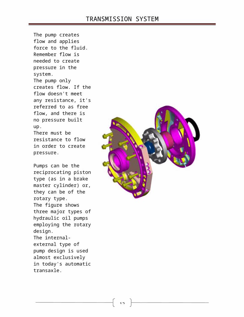
The pump creates flow and applies force to the fluid. Remember flow is needed to create pressure in the system.The pump only creates flow. If the flow doesn't meet any resistance, it's referred to as free flow, and there is no pressure built up. There must be resistance to flow in order to create pressure.
Pumps can be the reciprocating piston type (as in a brake master cylinder) or, they can be of the rotary type.
The figure shows three major types of hydraulic oil pumps employing the rotary design. The internal-external type of pump design is used almost exclusively in today's automatic transaxle.

10
TRANSMISSION SYSTEM
VALVE MECHANISM
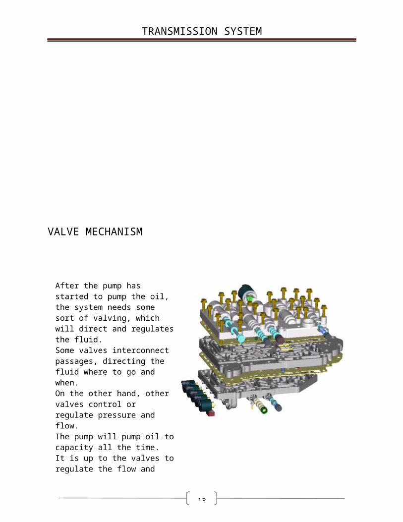
After the pump has started to pump the oil, the system needs some sort of valving, which will direct and regulates the fluid. Some valves interconnect passages, directing the fluid where to go and when. On the other hand, other valves control or regulate pressure and flow. The pump will pump oil to capacity all the time. It is up to the valves to regulate the flow and pressure in the system. One important principle to learn about valves in automatic transaxle hydraulics is that the valves can move in one direction or the other in a passage, opening or closing another passage. The valve may either move left or right, according to which force can overcome the other. When the spring force is greater than the hydraulic force, the valve is pushed to the left, closing the passage. When the hydraulic force builds up enough force to overcome the spring force, the hydraulic force will push the valve to the right compressing the spring even more, and re-directing the fluid up into the passage. When there is a loss of pressure due to the re-direction of oil, the spring force will close the passage again. This system is called a balanced valve system. A valve that only opens and closes passages or circuits, is called a relay valve.
11
TRANSMISSION SYSTEM
AN ACTUATING MECHANISM
Once the fluid has passed through the lines, valves, pump, etc., it will end up at the actuating mechanism. This is the point where the hydraulic force will push a piston causing the piston to do some sort of mechanical work. This mechanism is actually the dead end that the oil pump flow will finally encounter in the system. This dead end causes the pressure to build up in the system.
The pressure works against some surface area (piston) and causes a force to be applied. In hydraulics and transaxle technology, the actuating mechanism is also termed a servo. A servo is any device where an energy transformation takes place causing work as a result. The clutch assemblies found in the alpha automatic transaxle are actually servos, but they are termed "clutch" for ease of identification.
12
TRANSMISSION SYSTEM
Terms for torque converter
Element A factor has a function to multiply and transmit the power by oil flows. (Impeller, Turbine, Reactor (Stator): 3 Elements)
Stage The number of turbine (output element)Phase The number of functional change inside torque converterMax. DIA. ofFlow Path The factor effects the capacity of torque converter( 230, 240 ..)
Design Path The average valid oil path to define the inlet and outlet blade angle, radius
Torus Section The axis directional section of flow circuit inside of torque converterImpeller The power input element (usually it called "pump")Turbine The power output elementStator The reacting element (It determines the capacity of OWC)Shell The most outer wall of torus sectionCore The most inner wall of torus section
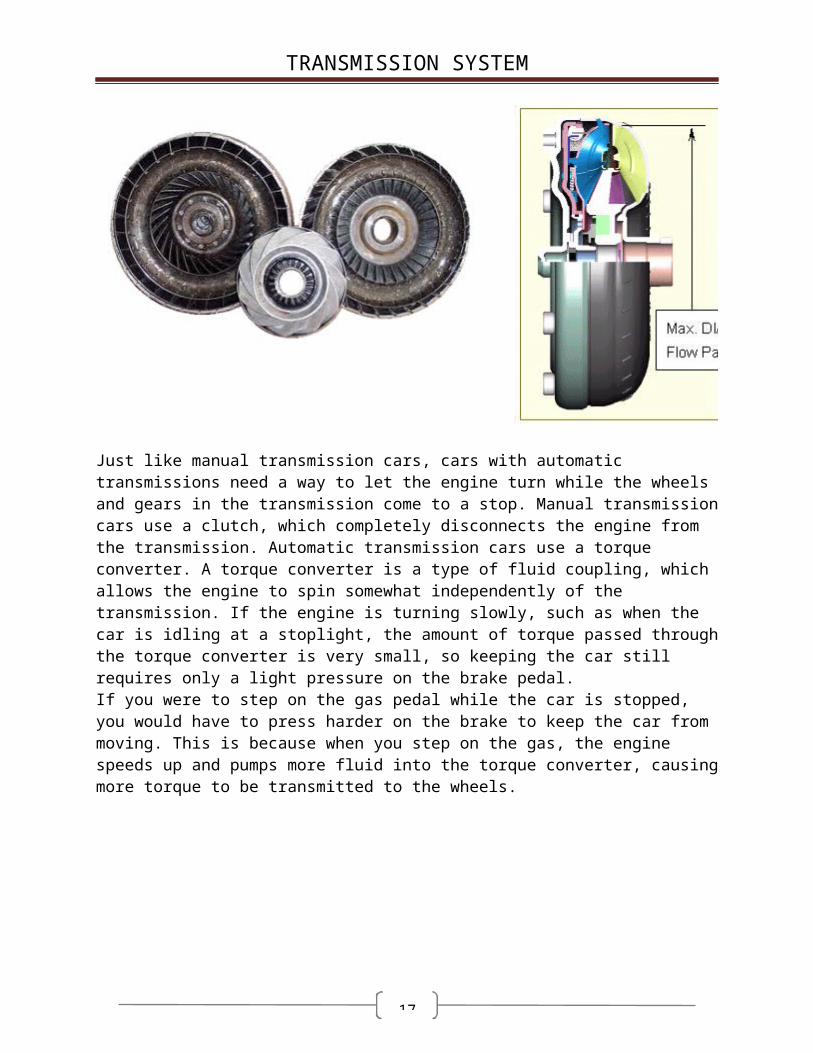
Just like manual transmission cars, cars with automatic transmissions need a way to let the engine turn while the wheels and gears in the transmission come to a stop. Manual transmission
13
TRANSMISSION SYSTEM
cars use a clutch, which completely disconnects the engine from the transmission. Automatic transmission cars use a torque converter. A torque converter is a type of fluid coupling, which allows the engine to spin somewhat independently of the transmission. If the engine is turning slowly, such as when the car is idling at a stoplight, the amount of torque passed through the torque converter is very small, so keeping the car still requires only a light pressure on the brake pedal. If you were to step on the gas pedal while the car is stopped, you would have to press harder on the brake to keep the car from moving. This is because when you step on the gas, the engine speeds up and pumps more fluid into the torque converter, causing more torque to be transmitted to the wheels.
In addition to the very important job of allowing your car come to a complete stop without stalling the engine, the torque converter actually gives your car more torque when you accelerate out of a stop. Modern torque converters can multiply the torque of the engine by two to three times. This effect only happens when the engine is turning much faster than the transmission. At higher speeds, the transmission catches up to the engine, eventually moving at almost the same speed. Ideally, though, the transmission would move at exactly the same speed as the engine, because this difference in speed wastes power. This is part of the reason why cars with automatic transmissions get worse gas mileage than cars with manual transmissions. To counter this effect, some cars have a torque converter with a lockup clutch. When the two halves of the torque converter get up to speed, this clutch locks them together, eliminating the slippage and improving efficiency.
14
TRANSMISSION SYSTEM
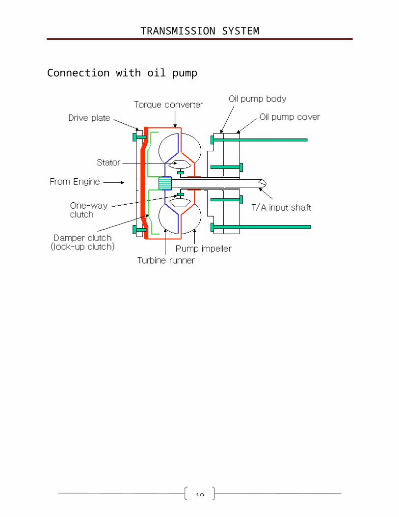
Connection with oil pump

15
TRANSMISSION SYSTEM
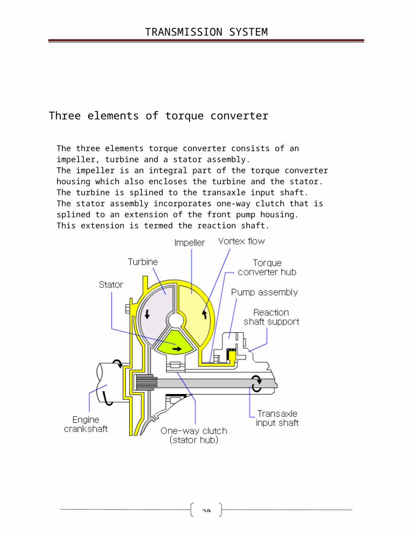
Three elements of torque converter The three elements torque converter consists of an impeller, turbine and a stator assembly. The impeller is an integral part of the torque converter housing which also encloses the turbine and the stator. The turbine is splined to the transaxle input shaft. The stator assembly incorporates one-way clutch that is splined to an extension of the front pump housing.This extension is termed the reaction shaft.

16
TRANSMISSION SYSTEM
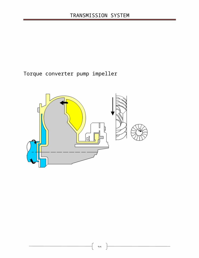
Torque converter pump impeller
17
TRANSMISSION SYSTEM
Turbine The turbine is the driven, or output, member of the converter.
The design of the turbine is similar to that of the impeller except that the turbine blades are curved in the opposite direction to the impeller blades.
Fluid from the impeller strikes the turbine blades and causes the turbine to rotate along with the impeller, thus turning the input shaft of the transaxle in the same direction as that of the engine crankshaft.

18
TRANSMISSION SYSTEM
Stator assembly The fluid leaving the turbine returns to the impeller by a third set of blades known as the stator assembly. The stator is mounted on a stationary shaft that is an integral part of the oil pump. The one-way clutch permits the stator to rotate only in the same direction as the impeller. The clutch locks the stator to the shaft in order to provide the torque multiplication effect.
19
TRANSMISSION SYSTEM
Stator action within the T/C When the vehicle stationary, the turbine is also stationary. As the engine begins to rotate, the oil is thrown into the turbine from the impeller with a great amount of force; due to the speed differential between the two members.The tendency for a bounce-back effect exists, as explained before. With this condition, the oil is leaving the trailing edges of the turbine vanes in a "hindering" direction. That is, if it's direction were not changed before it entered the impeller, it would tend to slow the impeller down. Under stall conditions, the oil strikes the faces of the stator vanes and tries to turn the stator opposite engine rotation. The one-way clutch locks up and holds the stator stationary. Now, as the oil strikes the stator vanes, it is turned in a "helping" direction before it enters the impeller. This circulation from impeller to turbine, turbine to stator, and stator back to impeller can produce a maximum torque multiplication of roughly 2.17:1.As vehicle speed increases, turbine speed approaches impeller speed and the torque multiplication drops off 1:1. At this point, the oil begins to strike the backs of the stator vanes. This causes the stator to start freewheeling, or to overrun. In effect, the stator gets out of the way of the oil and thereby no longer enters into the torque converter action. The converter then acts like a fluid coupling.
20
TRANSMISSION SYSTEM
21
TRANSMISSION SYSTEM
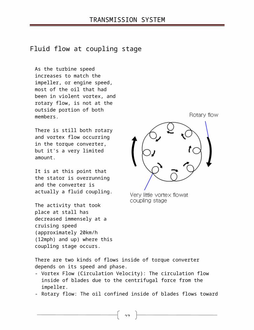
Fluid flow at coupling stage As the turbine speed increases to match the impeller, or engine speed, most of the oil that had been in violent vortex, and rotary flow, is not at the outside portion of both members.
There is still both rotary and vortex flow occurring in the torque converter, but it's a very limited amount.
It is at this point that the stator is overrunning and the converter is actually a fluid coupling.
The activity that took place at stall has decreased immensely at a cruising speed (approximately 20km/h (12mph) and up) where this coupling stage occurs. There are two kinds of flows inside of torque converter depends on its speed and phase. - Vortex Flow (Circulation Velocity): The circulation flow inside of blades due to the
centrifugal force from the impeller.- Rotary flow: The oil confined inside of blades flows toward impeller rotating direction.

22
TRANSMISSION SYSTEM
[The flows of vortex or rotary]
[The impeller vortex flow]
Those two kinds of flows (vortex and rotary) can be analyzed by vector diagram as follows.
23
TRANSMISSION SYSTEM
[The vector diagram of vortex and rotary flow]
[The vector diagram depends on the velocity ratio 'e' ]

24
TRANSMISSION SYSTEM
[The flows depends on the velocity ratio 'e']

25
TRANSMISSION SYSTEM
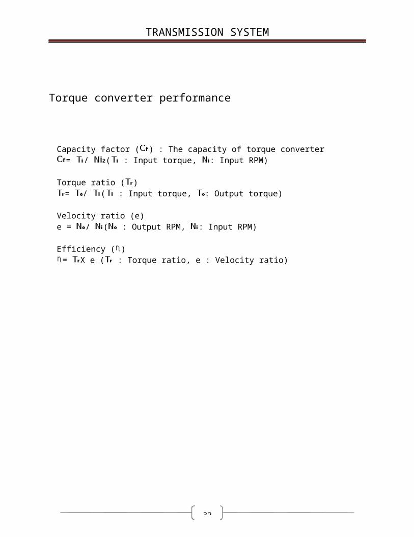
Torque converter performance
Capacity factor ( ) : The capacity of torque converter
= / ( : Input torque, : Input RPM)
Torque ratio ( ) = / ( : Input torque, : Output torque)
Velocity ratio (e)e = / ( : Output RPM, : Input RPM)
Efficiency ( )= X e ( : Torque ratio, e : Velocity ratio)

26
TRANSMISSION SYSTEM
Optimal design of torque convertor
When the automotive designer selects the torque converter, the stall rpm of torque converter should be positioned between 2,000rpm to 2,600rpm under the condition of wide-open throttle. If the stall rpm is out of above zone, there are some demerits as follows.- In case of 2,000 rpm or less: Capacity factor ( ) is high.
(Because input torque is high but input rpm is low) In this case, the fuel consumption at engine idle condition is poor and the foot braking effort will be high at idle situation because of higher input torque.
- In case of 2,600 rpm or more : Capacity factor ( ) is low. (Because input torque is low but input rpm is high) In this case, the overall fuel consumption will be poor and it will result in higher engine noise.
27
TRANSMISSION SYSTEM
Gear-ratio-to-engine match up is critical in automatic transaxles. We defined stall speed as the impeller speed(rpm's) when maximum torque multiplication is produced. To provide maximum torque to the drive wheels, we would like stall speed to be the same as the speed of the engine when it produces maximum torque. Maximum engine torque rpm's should match torque converter stall speed rpm's for optimum performance. If the torque converter is too large or too small for the application, driving performance may be seriously degraded. If the converter is too low a capacity for the engine, the engine will run at a higher than optimum rpm when transmitting maximum torque. If the converter is too large, too high a capacity for the engine, the engine won't be able to drive the impeller to the maximum torque point.The normal practice is to match stall speed and peak torque engine rpm's. The massage is that field mechanics should not try to alter the converter-engine size match up engineered by the manufacturer.

28
TRANSMISSION SYSTEM
Lock-up converters The idea of the lock-up torque converter is not new - it's has been around for a number of years. Benefits of the lock-up system are threefold: 1. Better fuel economy.2. Lower transmission operating temperature during highway operation.3. Less engine speed during highway operation. The lock-up feature has been added with no loss whatsoever in the normal smooth operation of the transaxle, in fact, most car drivers will not be aware of the lock-up action at all.

29
TRANSMISSION SYSTEM
Fluid couplings all slip a little Although fluid couplings provides smooth, shock-free power and torque transfer, it is natural for all fluid drives to slip somewhat, even in drive.
The lock-up clutch improves fuel economy by eliminating torque converter slip in direct gear above a predetermined speed.
With a conventional converter in direct drive, both the impeller and the turbine are rotating at approximately the same speed. The stator is freewheeling, and no torque multiplication is produced or needed. If we can now lock the turbine and the impeller together, we can achieve a condition of zero slippage in direct drive.

30
TRANSMISSION SYSTEM
Piston locks turbine to Impeller A moveable piston was added to the turbine, and friction material was added to the inside of the impeller housing. Now, by means of oil pressure, the turbine piston can be forced against the impeller friction material resulting in total converter lock-up.
[The torque converter clutch has a force of approximately 800pounds when applied. This value is less than that of a manual transmission clutch, because the lock-up clutch applies only in direct drive with the vehicle in motion. This is a much lower load than the required to engage a manual transmission from a dead stop. A greater force is not required to lock together the two members of the torque converter with the vehicle at speed.]

31
TRANSMISSION SYSTEM
The result is a straight-through 1:1 mechanical connection of the engine and transmission plus the elimination of all hydraulic fluid slippage in direct drive.
Dampers springs Since the locked-up mode has eliminated the vibration damping effect of the conventional fluid coupling, any torsion vibration load transmitted by the engine is now absorbed by eight damper springs between the lock-up piston and the turbine.
The lock-up mode is activated only in direct drive. Even though there is some hydraulic slippage in all gears, the lock-up feature cannot not be applied in low and second gears because lock-up eliminates the torque multiplication necessary for acceleration. This means lock-up only occurs after the 2-3 up shift.
[Lock-up could occur in lower gears if the *failsafe valve sticks. Up shifts would be harsher than normal, and there would be a loss of performance in lower
32
TRANSMISSION SYSTEM
gears due to the loss of torque multiplication in the torque converter]
* Fail-safe valve: Damper clutch control solenoid valve.
ATF (Automatic Transaxle Fluid) When new, ATF (Automatic Transaxle Fluid) should be red. The red dye is added to distinguish it from engine oil or antifreeze. As the vehicle is driven, the transaxle fluid will begin to look darker.
The color may eventually appear light brown. Also, the dye, which is not an indicator of fluid quality, is not permanent. Therefore, do not use fluid color as a criterion for replacing the transaxle fluid. However, further investigation of the automatic transaxle is required if,- The fluid is dark brown or black.- The fluid smells burnt. Metal particles can be seen or felt on the dipstick.

33
TRANSMISSION SYSTEM
ATF Temperature VS Oil Level