Embed Size (px)
Citation preview
Outsource Inspections
1 Revised on 03/16/11
All work on MoDOT right of way to be in accordance with the following:
• The latest editions of MoDOT’s Standard Drawings, MoDOT’s Standard Specifications for Highway Construction and the Manual for Uniform Traffic Control Devices (MUTCD).
• Permit Plans stamped – “Permit Plans (Date) MODOT District 6”. • For material testing, follow Addendum A.
The duties (not inclusive) of an Outsource Inspector will be as follows: 1. Communication
• Work closely with MoDOT’s Permit Inspector. i. Attend any preconstruction meetings.
ii. Keep Permit Inspector informed by e-mail, phone, fax, daily log, etc. iii. Submit a daily log to the Permit Inspector within 48 hours. iv. Submit copies of the certifications and test results that are required
and/or requested to the Permit Inspector. v. Inform the Permit Inspector of any proposed changes (They must
approve any construction changes). vi. Keep Permit Inspector advised of any controversial issue that arises
during the permit work. vii. Notify Permit Inspector of any changes in Outsource Inspector for
vacations, etc.
2. MoDOT’s Permit Plans • Review plans to become familiar with the work that has been approved. • Check the contractor’s construction layouts to ensure they are not deviating
from the approved plans.
3. Project File (to contain items below) • Copy of Permit • Permit Plans • Daily Log (to contain items below)
i. Weather ii. Major operation of the day
iii. Conversations pertaining to the work iv. Comments as to how work is progressing v. Note anything that might be pertinent after job is complete or might
cause a future problem for MoDOT

2 Revised on 03/16/11
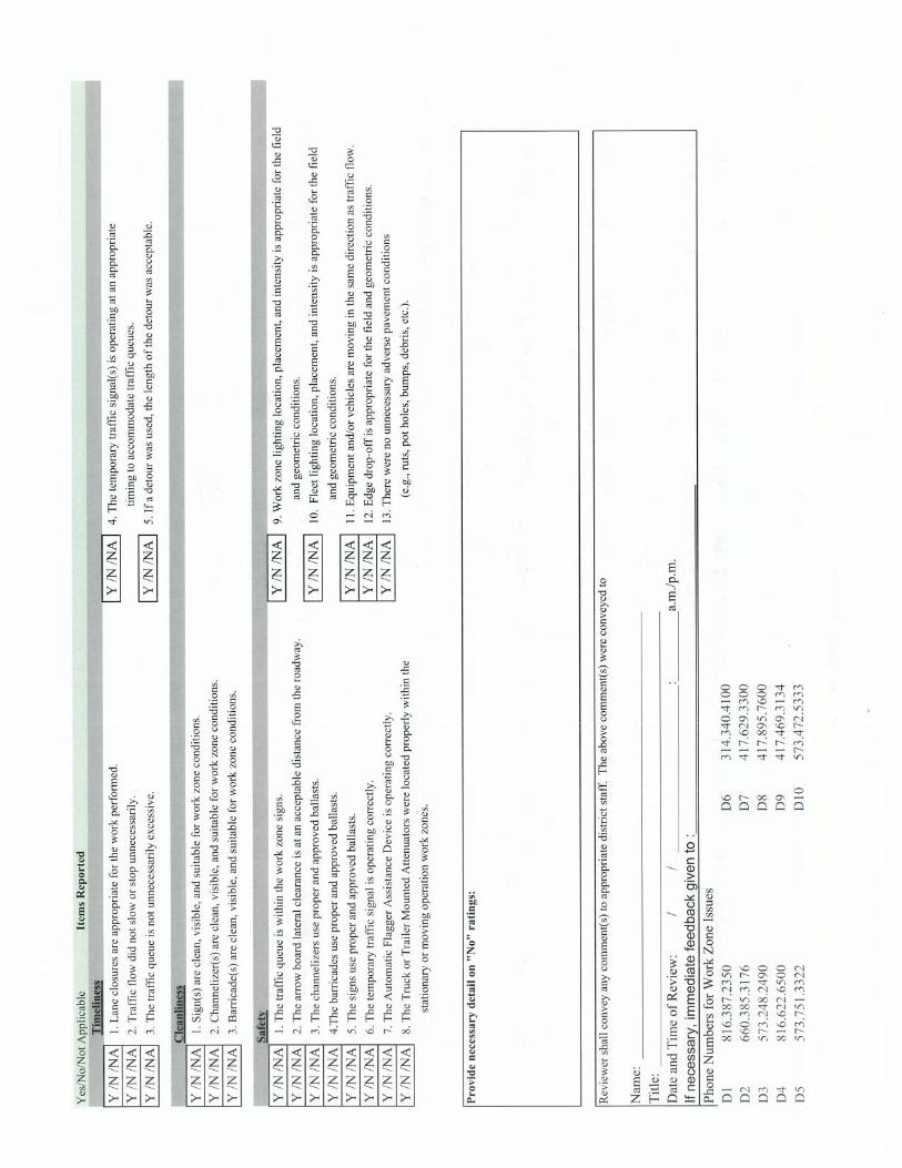
4. Traffic Control (Standard Specifications-Section 1063 and MUTCD Manual-Part VI)
• Verify that a MoDOT Workzone Verification Number has been given for any lane closures.
• Compare the Traffic Control Plan with the current conditions to see if any adjustments are needed.
• Submit Daily Workzone Inspection Form. • When not in use, ensure all traffic control devices are located in an area that
will not cause a hazard to the traveling public. • Make sure all traffic control devices are removed as soon as practical when
they are no longer needed. 5. Grading (Standard Specifications-Division 200)
• Make sure the contractor is following MoDOT spec’s concerning cuts and fills when doing grading.
6. Erosion Control (Standard Specifications-Section 806)
• Check that the silt fence, ditch checks, etc. are in place and working (if required on right of way).
• Check periodically for any breaches.
7. Pipes (Standard Specifications-Sections 725-730 & 732) • Check trench width, check pipe placement and see that backfill material is
free of large rocks, and debris. • Check size, length, condition and type of pipes. • Ensure flow lines are correct. • Check concrete pipe joints to ensure that they are sealed. Also, check that
the concrete pipes are installed with the bells in the correct direction. • Check corrugated metal pipes to ensure they are banded together properly.
8. Drainage Structures (Standard Specifications-Sections 731-733) • Check to ensure that the correct inlets are being used and built with the
correct materials and that the flow lines are correct. • If the structure is cast in place, make sure all support materials are removed. • Inlets and manholes located in the pavement (roadway surface) must have
locking lids.

3 Revised on 03/16/11
9. Base for Pavements (Standard Specifications-Division 300) • Make sure of correct grade and correct material. • Check thickness and compaction of each lift (requiring certifications where
necessary).
10. Pavements (Standard Specifications-Divisions 400 & 500)
• Concrete i. Check joint spacing, use of dowel baskets and/or tie bars and type of
finish. ii. Test air, slump and cylinders to ensure minimum requirements are
met. iii. Check cores for thickness and the time of placement so that
placement is done uninterrupted. Paver should proceed as continuously as possible.
iv. Monitor or perform surface smoothness tests with profilograph. v. Monitor timing of texturing and curing and surface texture test.
vi. Check joint sawing for time of sawing, spacing, depth, width, curing and sealing (if necessary).
• Asphalt
i. Check that loads are covered and that temperature is of acceptable range for mix.
ii. Check for segregation, separation and tack (if needed). iii. Check that paver maintains a speed that will minimize stop and start
operations. iv. Check cores and density tests to ensure compaction. v. Check surface with profilograph or straightedge for ride quality.
11. ADA Pedestrian Facilities
• See the attached ADA Post Inspection Checklist for inspection checks.
12. Signing (Standard Specifications-Section 903 and Addendum A, Section 1-3) • Check signing for size, reflectivity (NCHRP 350 compliant), and that the
message matches what is shown on the plans. • Check location of sign and make sure correct sign support is being used. • Check to ensure sign is placed at the correct height above the ground or
pavement. • Check overhead sign trusses and provide certifications.
4 Revised on 03/16/11
13. Striping (Standard Specifications-Section 1048) • Follow striping plan to ensure work is being done as planned. • Check that removal of any existing striping is done by a mechanical device
(grinder, sander, etc) or by sandblasting. It cannot be covered with oils, paint, etc.
• Check reflectivity of new striping. • Check mil thickness. • Use MoDOT’s Traffic Striping Manual or Policy to insure that materials,
locations and procedures are followed.
14. Lighting & Signals (Standard Specifications-Sections 901 & 902) • Use the attached sheet and checklist to ensure ALL work has been
completed and inspected.
15. Earthwork (Standard Specifications-Division 800) • Curbs are to be backfilled to top of the back of curb. • Manholes and inlets are to be at ground level, sloped if necessary to match
the surrounding earth. • All earth areas should be graded, seeded and mulched with straw or sod.
16. Guardrail (Standard Specifications-Section 606)
• Check for correct type. • Check for correct end treatment. • Check for correct installation.
17. Authority to Suspend Work
• Failing Test Results i. Reject if not passing and notify MoDOT
• Unsafe Conditions i. Inform contractor to correct before continuing work and notify
MoDOT • Requirements of Permit not met
i. Not following plans ii. Not submitting lane closure requests
• Changes to Plans i. MoDOT permit inspector has to approve any changes of plans,
whether verbal or written • Non-Compliance of Contractor
i. Job should be shut down if contractor does not comply with any of the above and MoDOT should be notified
5 Revised on 03/16/11
18. Semi-Final Inspection • Check to ensure that no silt has collected in any pipes, inlets or manholes. • Inspect inlets and manholes in the pavement (roadway surface) to ensure
they have locked lids. • Make a general inspection of the work area.
i. Make sure everything is in place that is called for in the permit. ii. Make sure the work area has been cleared of all excess items (signs,
cones, lumber, forms, etc.). iii. Make sure that the paving surface is free of dirt, mud, rocks and other
debris. iv. Make sure the MoDOT right of way has been policed with no debris
being left.
19. Final Inspection • Contact Permit Inspector
i. Walk project ii. Make a punch list of any items that need attention.
iii. Notify Developer (or developer’s representative) of any items that need attention.
20. NOTIFY PERMIT INSPECTOR WHEN ALL FINAL INSPECTION ITEMS HAVE BEEN COMPLETED.

MoDOT Permit Construction Observation DAILY WORK REPORT
Any questions, contact your MoDOT Permit Inspector, __________________________ at ______-______-________ or by fax at ______-______-________
Sheet ______ of ______ Permit # / Project: ________________________________________________ Site Inspector: ________________________________________ Route / County: ________________________________________________ Date: ________________________________________ Contractor: ________________________________________________ Inspector’s Arrival Time: ____________________________ Supervisor/Foreman: ________________________________________________ Inspector’s Departure Time: ____________________________ Air Temperature Weather 1. Clear 5. Sleet Road 1. Dry 4. Ice
Conditions 2. Cloudy 6. Freezing Rain Conditions 2. Wet 5. Mud High __________ 3. Rain 7. Fog or Mist 3. Snow Low __________ 4. Snow Any tests performed? yes no If yes, list all tests performed and attach results: _______________________________________________________________________________________ Traffic Control: Are all traffic control devices placed properly according to the Traffic Control Plan or any approved revisions and in good condition? yes no n/a Note Any Deficiencies: __________________________________________________________________________________________________________ Date & Time Corrections Made: ___________________________________________________________________________________________________ Detailed Description of Work Performed:______________________________________________________________________________________________________________________________________________________________________________________________________________________________________________________________________________________________________________________________________________________________________________________________________________________________________________________________________________________________________________________________________________________________________________________________________________________________________________________________________________________________________________________________________________________________________________________________________________________________________________________________________________________________________________________________________________________________________________________________________________________________________________________________________________________________________________________________________________________________________________________________________________________________________________________________________________________________________________________________________________________________________________________________________________________________________________________________________________________________________________________________________________________________________________________________________________________________________________________________________________________________________


Addendum A
1 Revised on 6/19/07
1. MATERIALS TESTING
1. Job control samples and tests shall be run by an independent inspection company as the work progresses to assure that the project is constructed in compliance with applicable specifications. All project sampling and testing of materials shall be performed by the independent inspection company's personnel. The independent inspection company shall have adequate equipment to perform all required tests and personnel capable of properly operating the equipment. Test reports or certifications are necessary for all materials incorporated into the work. The test report or certification must show the quantity of material being reported and if it meets the specifications. Actual test results of materials tested are preferred, although certifications from the supplier are acceptable on certain items. The independent inspection company should contact MoDOT district personnel for guidelines.
2. In order to facilitate the acceptance of small quantities of materials with a minimum of inspection and testing, MoDOT has approved a schedule of materials quantities which may be accepted without complying with the sampling and testing requirements noted above. This schedule is listed in Section 2 of this addendum. Any major deviation from this schedule should be cleared through MoDOT.
3. The following procedures have been established for the acceptance of structural steel.
Shop drawings shall be submitted to the engineer for review and approval. The approval will cover only the general design features, and in no case shall this approval be considered to cover errors or omissions in the shop drawings. The contractor shall utilize a fabricator who is currently certified for Category III by the American Institute of Steel Construction (AISC). All welding operations, including material and personnel, shall meet the American Welding Society (AWS) specifications. The consultant has the option of inspecting the steel units during fabrication or requiring the fabricator to furnish a certification of contract compliance and substantiating test reports. In addition, the following reports will be required.
(a) Certified mill test reports, including results of chemical and physical tests on all structural steel as furnished.
(b) Non-destructive testing reports.
The consultant must verify and document that dimensions of the units were checked at the job and found to be in compliance with the shop drawings.

2. ACCEPTANCE OF SMALL QUANTITIES OF MATERIALS The following guidelines may be used to reduce the amount of engineering control and sampling and testing for relatively small quantities of materials. These guidelines are intended for use on materials that will not adversely affect the traffic carrying capacity of the completed facility, and are not to be used for concrete in major structures, permanent mainline or ramp pavements or other structurally critical items. 1. Sampling and Testing of Small Quantities of Miscellaneous Materials
Samplings and testing of small quantities of miscellaneous materials may be waived by the project engineer and the material accepted on the basis of one of the two following methods.
(a) Acceptance on the basis of visual examination, provided the source has recently furnished similar material found to be satisfactory under the state's normal sampling and testing procedures.
(b) Acceptance on the basis of certification by the producer or supplier stating that the material complies with the specification requirements.
The primary documentation of acceptance of material under either of these two methods should be provided by the project engineer or individual approving the material. The documentation may consist of a daily inspector's report with a statement as to the basis of acceptance of the material and the approximate quantity of material covered by the acceptance.
The following quantities of material may be accepted under the methods indicated above.
(a) Aggregate - Not to exceed approximately 100 tons per day nor more than approximately 500 tons per project.
(b) Bituminous Mixtures - Not to exceed approximately 50 tons per day nor more than approximately 250 tons per project.
(c) Bituminous Material – Not to exceed approximately 100 gallons per project. (d) Paint - Not to exceed approximately 20 gallons per project - acceptance to be
based on weights and analysis on the container label. (e) Lumber - Recognized commercial grades only may be used.
(f) Masonry Items - Subject to checking for nominal size and visual inspection -not to exceed approximately 100 pieces.
(g) Plain concrete or clay pipe - 100 feet.
2 Revised on 6/19/07

2. Portland Cement Concrete
Concrete for the following items may be accepted on the basis of occasional conventional field sampling and testing for characteristics such as slump and air, where specified, and test cylinders, with only intermittent or random plant inspection as deemed necessary for control by the project engineer. Under this system, arrangements should be made for the producer to state the following on the delivery ticket accompanying each load of concrete: name of concrete plant, serial number of the ticket, date and truck number, name of contractor, specific project, route and county designation, specific class of concrete and quantity of concrete in cubic yards. Only concrete that meets MoDOT’s requirements shall be used.
(a) Sidewalk (b) Curb and/or gutter (c) Concrete base course (d) Pavement repair (e) Median barrier or strip (f) Slope protection (g) Paved ditch (h) Ditch liner (i) Guardrail anchorage (j) Fence posts (k) Pipe headwalls and collars (l) Manholes (m) Drop inlets (n) Lighting, signal and sign bases (o) Pull boxes (p) Grout (q) Flowable fill
3 Revised on 6/19/07
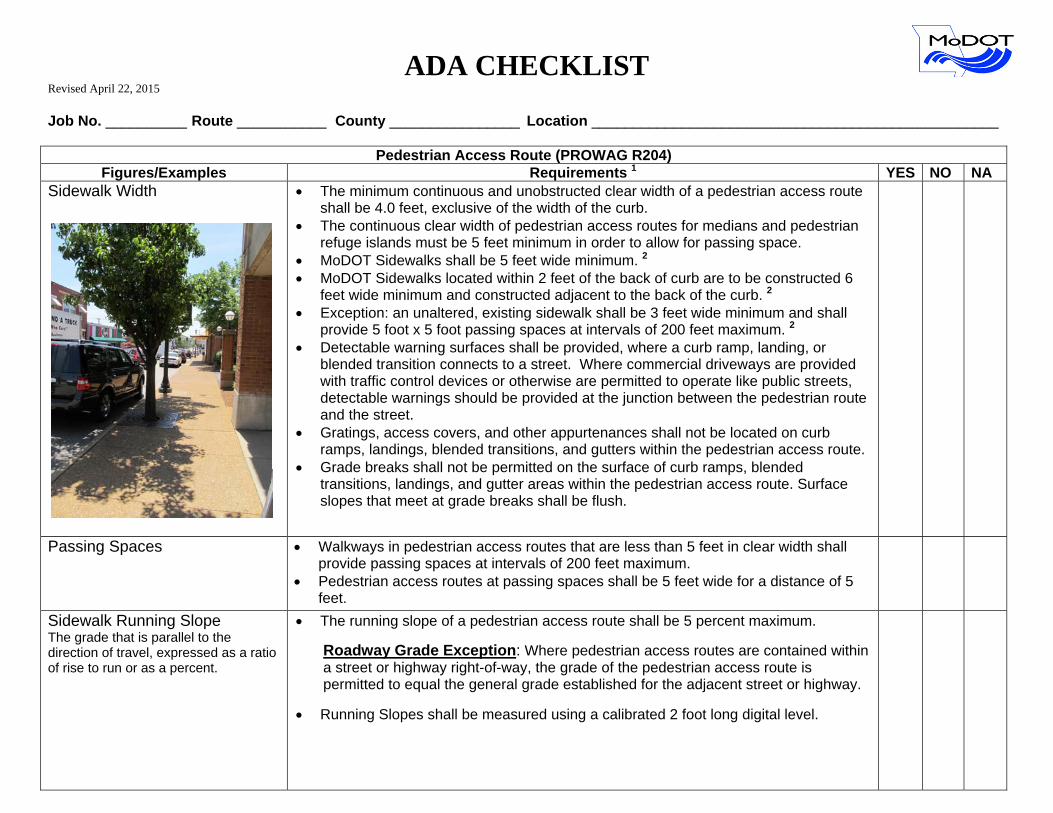
ADA CHECKLIST Revised April 22, 2015
Job No. __________ Route ___________ County ________________ Location __________________________________________________
Pedestrian Access Route (PROWAG R204)
Figures/Examples Requirements 1 YES NO NA Sidewalk Width
The minimum continuous and unobstructed clear width of a pedestrian access route shall be 4.0 feet, exclusive of the width of the curb.
The continuous clear width of pedestrian access routes for medians and pedestrian refuge islands must be 5 feet minimum in order to allow for passing space.
MoDOT Sidewalks shall be 5 feet wide minimum. 2 MoDOT Sidewalks located within 2 feet of the back of curb are to be constructed 6
feet wide minimum and constructed adjacent to the back of the curb. 2 Exception: an unaltered, existing sidewalk shall be 3 feet wide minimum and shall
provide 5 foot x 5 foot passing spaces at intervals of 200 feet maximum. 2 Detectable warning surfaces shall be provided, where a curb ramp, landing, or
blended transition connects to a street. Where commercial driveways are provided with traffic control devices or otherwise are permitted to operate like public streets, detectable warnings should be provided at the junction between the pedestrian route and the street.
Gratings, access covers, and other appurtenances shall not be located on curb ramps, landings, blended transitions, and gutters within the pedestrian access route.
Grade breaks shall not be permitted on the surface of curb ramps, blended transitions, landings, and gutter areas within the pedestrian access route. Surface slopes that meet at grade breaks shall be flush.
Passing Spaces
Walkways in pedestrian access routes that are less than 5 feet in clear width shall provide passing spaces at intervals of 200 feet maximum.
Pedestrian access routes at passing spaces shall be 5 feet wide for a distance of 5 feet.
Sidewalk Running Slope The grade that is parallel to the direction of travel, expressed as a ratio of rise to run or as a percent.
The running slope of a pedestrian access route shall be 5 percent maximum. Roadway Grade Exception: Where pedestrian access routes are contained within a street or highway right-of-way, the grade of the pedestrian access route is permitted to equal the general grade established for the adjacent street or highway.
Running Slopes shall be measured using a calibrated 2 foot long digital level.
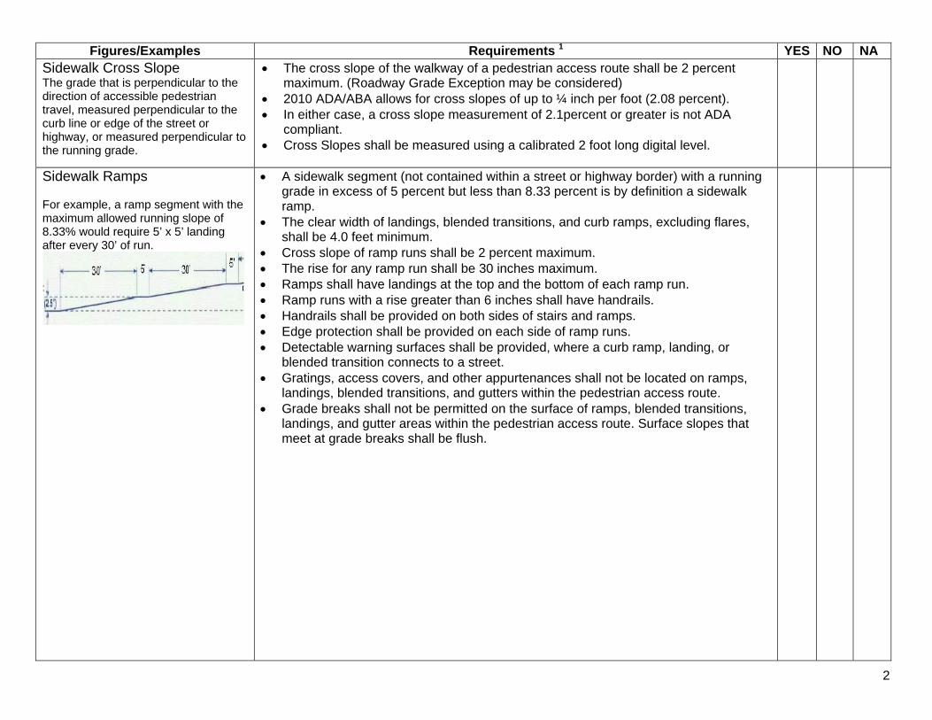
2
Figures/Examples Requirements 1 YES NO NA Sidewalk Cross Slope The grade that is perpendicular to the direction of accessible pedestrian travel, measured perpendicular to the curb line or edge of the street or highway, or measured perpendicular to the running grade.
The cross slope of the walkway of a pedestrian access route shall be 2 percent maximum. (Roadway Grade Exception may be considered)
2010 ADA/ABA allows for cross slopes of up to ¼ inch per foot (2.08 percent). In either case, a cross slope measurement of 2.1percent or greater is not ADA
compliant. Cross Slopes shall be measured using a calibrated 2 foot long digital level.
Sidewalk Ramps For example, a ramp segment with the maximum allowed running slope of 8.33% would require 5’ x 5’ landing after every 30’ of run.
A sidewalk segment (not contained within a street or highway border) with a running grade in excess of 5 percent but less than 8.33 percent is by definition a sidewalk ramp.
The clear width of landings, blended transitions, and curb ramps, excluding flares, shall be 4.0 feet minimum.
Cross slope of ramp runs shall be 2 percent maximum. The rise for any ramp run shall be 30 inches maximum. Ramps shall have landings at the top and the bottom of each ramp run. Ramp runs with a rise greater than 6 inches shall have handrails. Handrails shall be provided on both sides of stairs and ramps. Edge protection shall be provided on each side of ramp runs. Detectable warning surfaces shall be provided, where a curb ramp, landing, or
blended transition connects to a street. Gratings, access covers, and other appurtenances shall not be located on ramps,
landings, blended transitions, and gutters within the pedestrian access route. Grade breaks shall not be permitted on the surface of ramps, blended transitions,
landings, and gutter areas within the pedestrian access route. Surface slopes that meet at grade breaks shall be flush.
3
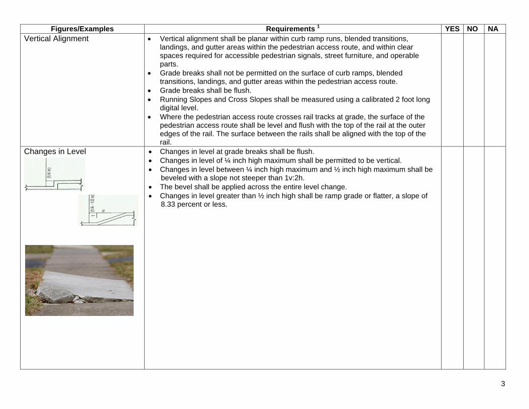
Figures/Examples Requirements 1 YES NO NA Vertical Alignment Vertical alignment shall be planar within curb ramp runs, blended transitions,
landings, and gutter areas within the pedestrian access route, and within clear spaces required for accessible pedestrian signals, street furniture, and operable parts.
Grade breaks shall not be permitted on the surface of curb ramps, blended transitions, landings, and gutter areas within the pedestrian access route.
Grade breaks shall be flush. Running Slopes and Cross Slopes shall be measured using a calibrated 2 foot long
digital level. Where the pedestrian access route crosses rail tracks at grade, the surface of the
pedestrian access route shall be level and flush with the top of the rail at the outer edges of the rail. The surface between the rails shall be aligned with the top of the rail.
Changes in Level
Changes in level at grade breaks shall be flush. Changes in level of ¼ inch high maximum shall be permitted to be vertical. Changes in level between ¼ inch high maximum and ½ inch high maximum shall be
beveled with a slope not steeper than 1v:2h. The bevel shall be applied across the entire level change. Changes in level greater than ½ inch high shall be ramp grade or flatter, a slope of
8.33 percent or less.
4
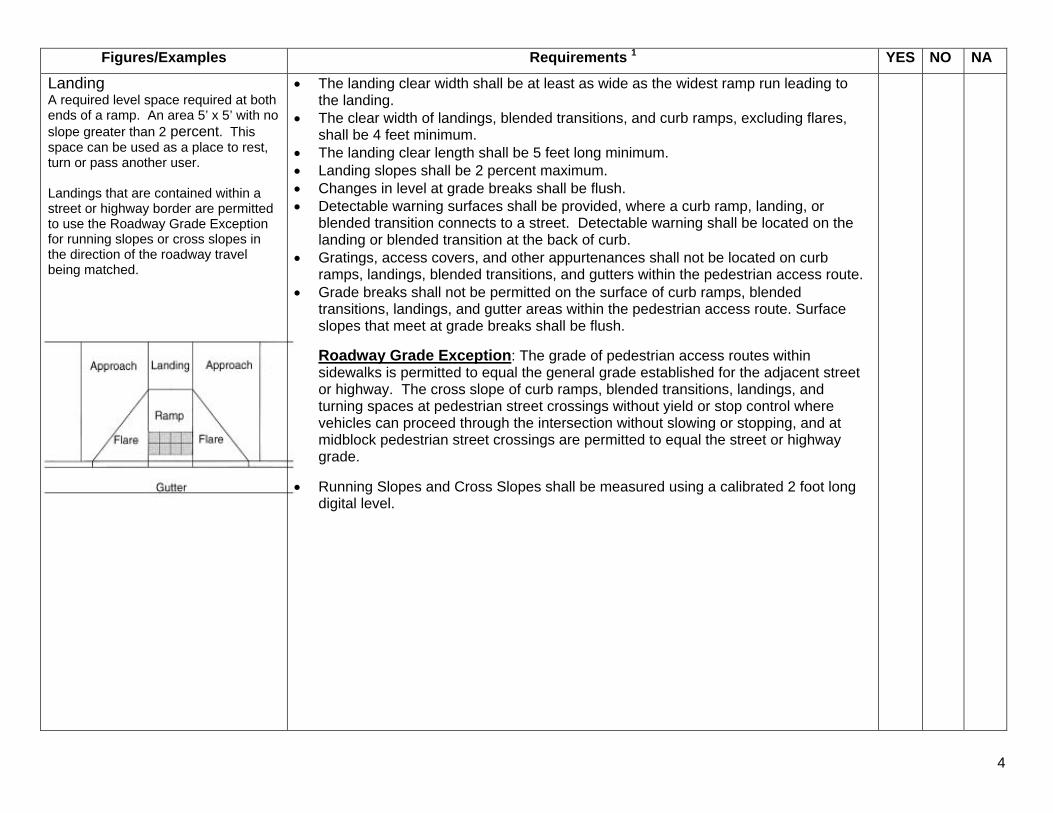
Figures/Examples Requirements 1 YES NO NA
Landing A required level space required at both ends of a ramp. An area 5’ x 5’ with no slope greater than 2 percent. This space can be used as a place to rest, turn or pass another user. Landings that are contained within a street or highway border are permitted to use the Roadway Grade Exception for running slopes or cross slopes in the direction of the roadway travel being matched.
The landing clear width shall be at least as wide as the widest ramp run leading to the landing.
The clear width of landings, blended transitions, and curb ramps, excluding flares, shall be 4 feet minimum.
The landing clear length shall be 5 feet long minimum. Landing slopes shall be 2 percent maximum. Changes in level at grade breaks shall be flush. Detectable warning surfaces shall be provided, where a curb ramp, landing, or
blended transition connects to a street. Detectable warning shall be located on the landing or blended transition at the back of curb.
Gratings, access covers, and other appurtenances shall not be located on curb ramps, landings, blended transitions, and gutters within the pedestrian access route.
Grade breaks shall not be permitted on the surface of curb ramps, blended transitions, landings, and gutter areas within the pedestrian access route. Surface slopes that meet at grade breaks shall be flush. Roadway Grade Exception: The grade of pedestrian access routes within sidewalks is permitted to equal the general grade established for the adjacent street or highway. The cross slope of curb ramps, blended transitions, landings, and turning spaces at pedestrian street crossings without yield or stop control where vehicles can proceed through the intersection without slowing or stopping, and at midblock pedestrian street crossings are permitted to equal the street or highway grade.
Running Slopes and Cross Slopes shall be measured using a calibrated 2 foot long digital level.

5
Figures/Examples Requirements 1 YES NO NA
Protruding objects on sidewalks and other pedestrian circulation paths shall not reduce the clear width required for pedestrian accessible routes.
Objects with leading edges more than 27 inches and not more than 80 inches above the finish floor or ground shall protrude 4 inches maximum horizontally into the circulation path.
Free-standing objects mounted on posts or pylons shall overhang circulation paths 4 inches maximum measured horizontally from the post or pylon base when located 27 inches minimum and 80 inches maximum above the finish floor or ground. The base dimension shall be 2.5 inches thick minimum. (2011 PROWAG R402.3)
Where a sign or other obstruction is mounted between posts or pylons and the clear distance between the posts or pylons is greater than 12 inches, the lowest edge of such sign or obstruction shall be 27 inches maximum or 80 inches minimum above the finish floor or ground.
Vertical clearance shall be 80 inches high minimum. Guardrails or other barriers shall be provided where the vertical clearance is less than 80 inches high. The leading edge of such guardrail or barrier shall be located 27 inches maximum above the finish floor or ground.
Guardrails or other barriers shall be provided where the vertical clearance is less than 80 inches high. The leading edge of such guardrail or barrier shall be located 27 inches maximum above the finish surface or ground.
Wrong Installation
Openings in floor and ground surfaces shall not allow passage of a sphere more than ½ inch diameter. Elongated openings shall be placed so that the long dimension is perpendicular to the dominant direction of travel.
Gratings, access covers, and other appurtenances shall not be located on curb ramps, landings, blended transitions, and gutters within the pedestrian access route.
Lift holes for manhole/utility covers shall not have an opening greater than ½ inch. Plugging of holes greater than ½ inch with a material approved by the engineer is acceptable as long as it complies with the changes in level requirements.
6
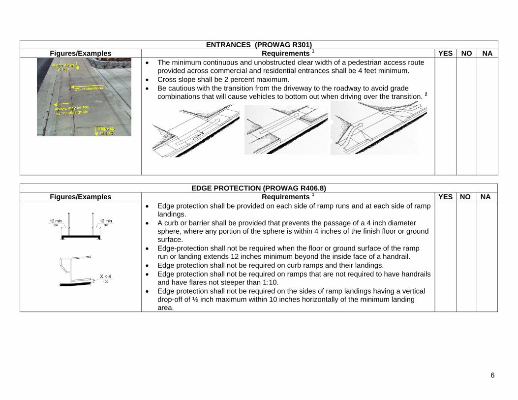
ENTRANCES (PROWAG R301) Figures/Examples Requirements 1 YES NO NA
The minimum continuous and unobstructed clear width of a pedestrian access route provided across commercial and residential entrances shall be 4 feet minimum.
Cross slope shall be 2 percent maximum. Be cautious with the transition from the driveway to the roadway to avoid grade
combinations that will cause vehicles to bottom out when driving over the transition. 2
EDGE PROTECTION (PROWAG R406.8)
Figures/Examples Requirements 1 YES NO NA
Edge protection shall be provided on each side of ramp runs and at each side of ramp landings.
A curb or barrier shall be provided that prevents the passage of a 4 inch diameter sphere, where any portion of the sphere is within 4 inches of the finish floor or ground surface.
Edge-protection shall not be required when the floor or ground surface of the ramp run or landing extends 12 inches minimum beyond the inside face of a handrail.
Edge protection shall not be required on curb ramps and their landings. Edge protection shall not be required on ramps that are not required to have handrails
and have flares not steeper than 1:10. Edge protection shall not be required on the sides of ramp landings having a vertical
drop-off of ½ inch maximum within 10 inches horizontally of the minimum landing area.

7
HANDRAIL AND PEDESTRIAN GUARDRAIL (PROWAG R408) Figures/Examples Requirements 1 YES NO NA
The clear width of walking surfaces shall be 4.0 feet minimum. Handrails are required on ramp runs with a rise greater than 6 inches and on certain
stairways. Handrails are not required on walking surfaces with running slopes less than 1:20. Where required, handrails shall be provided on both sides of stairs and ramps.
Handrails shall be continuous within the full length of each stair flight or ramp run. Inside handrails on switchback or dogleg stairs and ramps shall be continuous between flights or runs.
Top of gripping surfaces of handrails shall be 34 inches minimum and 38 inches maximum vertically above walking surfaces, stair nosings, and ramp surfaces. Handrails shall be at a consistent height above walking surfaces, stair nosings, and ramp surfaces.
Clearance between handrail gripping surfaces and adjacent surfaces shall be 1 1/2 inches minimum.
Handrail gripping surfaces with a circular cross section shall have an outside diameter of 1 1/4 inches minimum and 2 inches maximum.
Handrail gripping surfaces with a non-circular cross section shall have a perimeter dimension of 4 inches minimum and 6 1/4 inches maximum, and a cross-section dimension of 2 1/4 inches maximum.
Handrail gripping surfaces and any surfaces adjacent to them shall be free of sharp or abrasive elements and shall have rounded edges.
Handrails shall not rotate within their fittings. Ramp handrails shall extend horizontally above the landing for 12 inches minimum
beyond the top and bottom of ramp runs. Extensions shall return to a wall, guard, or the landing surface, or shall be continuous to the handrail of an adjacent ramp run.
At the top of a stair flight, handrails shall extend horizontally above the landing for 12 inches minimum beginning directly above the first riser nosing. Extensions shall return to a wall, guard, or the landing surface, or shall be continuous to the handrail of an adjacent stair flight.
At the bottom of a stair flight, handrails shall extend at the slope of the stair flight for a horizontal distance at least equal to one tread depth beyond the last riser nosing. Extension shall return to a wall, guard, or the landing surface, or shall be continuous to the handrail of an adjacent stair flight.
See Edge Protection section above (also PROWAG 406.8) for additional details.

8
STAIRWAYS (PROWAG R407) Figures/Examples Requirements 1 YES NO NA
All steps on a flight of stairs shall have uniform riser heights and uniform tread depths. Risers shall be 4 inches high minimum and 7 inches high maximum. Treads shall be 11 inches deep minimum.
Open risers are not permitted. The radius of curvature at the leading edge of the tread shall be 1/2 inch maximum.
Nosings that project beyond risers shall have the underside of the leading edge curved or beveled. Risers shall be permitted to slope under the tread at an angle of 30 degrees maximum from vertical. The permitted projection of the nosing shall extend 1 1/2 inches maximum over the tread below.
Stairs shall have handrails complying with PROWAG 2005 R408.
UNOBSTRUCTED REACH RANGES (PROWAG R404)
Figures/Examples Requirements 1 YES NO NA
Forward Reach Where a forward reach is unobstructed, the high forward reach shall be 48 inches
maximum and the low forward reach shall be 15 inches minimum above the finish floor or ground.
Side Reach Where a clear floor or ground space allows a parallel approach to an element and the
side reach is unobstructed, the high side reach shall be 48 inches maximum and the low side reach shall be 15 inches minimum above the finish floor or ground.
EXCEPTION: An obstruction shall be permitted between the clear floor or ground space and the element where the depth of the obstruction is 10 inches maximum. (2011 PROWAG R406.3)

9
CURB RAMPS (PROWAG R303) Figures/Examples Requirements 1 YES NO NA
A curb ramp, blended transition, or a combination of curb ramps and blended transitions shall connect the pedestrian access routes at each pedestrian street crossing.
15 Foot Rule: For a compliant curb ramp to exceed 8.33 percent running grade, its constructed length must exceed 15.0 feet.
The clear width of ramps, excluding the flares, shall be 4.0 feet minimum. Ramp runs shall have a running slope between 5 percent minimum and 8.33 percent
maximum but shall not require the ramp length to exceed 15.0 feet. Exception: 15 Foot Rule: The running slope for a curb ramp is not limited to 8.33 percent maximum if the constructed curb ramp length exceeds 15 feet in length.
Cross slope of ramp runs shall be 2 percent maximum. (Roadway Grade Exception may be considered)
The cross slope at midblock crossings shall be permitted to be warped to meet street or highway grade.
Ramps shall have landings at the top and the bottom of each ramp run. - The landing clear width shall be at least as wide as the widest ramp run leading to
the landing. - The landing clear length shall be 5.0 feet long minimum. - Ramps that change direction between runs at landings shall have a clear landing
5.0 feet minimum by 5.0 feet minimum. Handrails and Edge protection shall not be required on curb ramps and their landings. Curb height = 0 inches within curb ramp spaces. 2 Curb ramps must be flush with street. The counter slope of the gutter or street at the foot of a curb ramp, landing, or
blended transition shall be 5 percent maximum. (R303.3.5) The adjacent surfaces at transitions at curb ramps to walks, gutters, and streets shall
be at the same level. Flared sides with a slope of 10 percent maximum, measured parallel to the curb line,
shall be provided where a pedestrian circulation path crosses the curb ramp. - In alterations, where there is no landing at the top of curb ramps, curb ramp flares
shall be provided and shall not be steeper than 1:12. Detectable warning surfaces shall be provided, where a curb ramp, landing, or
blended transition connects to a street. Gratings, access covers, and other appurtenances shall not be located on curb
ramps, landings, blended transitions, and gutters within the pedestrian access route. Grade breaks shall not be permitted on the surface of curb ramps, blended
transitions, landings, and gutter areas within the pedestrian access route. Surface slopes that meet at grade breaks shall be flush.
Grade Breaks at the top and bottom of curb ramp runs shall be perpendicular to the direction of the ramp run.

10
Figures/Examples Requirements 1 YES NO NA
Perpendicular Ramps
X = 4’Min. Flared Sides in Pathway Flared Sides Not in Pathway
Roadway Grade Exception: Where curb ramps, landings and blended transitions are contained within a street or highway right-of-way, the grade of the pedestrian access route is permitted to be modified to equal the general grade established for the adjacent street or highway.
Perpendicular curb ramps shall have a running slope that cuts through or is built up to the curb at right angles or meets the gutter grade break at right angles.
The clear width of landings, blended transitions, and curb ramps, excluding flares, shall be 4.0 feet minimum.
The running slope shall be 5 percent minimum and 8.33 percent maximum but shall not require the ramp length to exceed 15.0 feet.
The cross slope at intersections shall be 2 percent maximum. (Roadway Grade Exception may be considered)
The cross slope at midblock crossings shall be permitted to be warped to meet street or highway grade. Roadway Grade Exception: The grade of pedestrian access routes within sidewalks is permitted to equal the general grade established for the adjacent street or highway. The cross slope of curb ramps, blended transitions, landings, and turning spaces at pedestrian street crossings without yield or stop control where vehicles can proceed through the intersection without slowing or stopping, and at midblock pedestrian street crossings are permitted to equal the street or highway grade.
A landing 4.0 feet minimum by 4.0 feet minimum shall be provided at the top of the curb ramp and shall be permitted to overlap other landings and clear space.
Flared sides with a slope of 10 percent maximum, measured parallel to the curb line, shall be provided where a pedestrian circulation path crosses the curb ramp.
If the flared sides are not in the pathway (grass next to ramp), then there is no maximum slope and can be vertical curbs. (See adjacent figure for further explanation.)
Detectable warning surfaces shall be provided, where a curb ramp, landing, or blended transition connects to a street.
Gratings, access covers, and other appurtenances shall not be located on curb ramps, landings, blended transitions, and gutters within the pedestrian access route.
Grade breaks at the top and bottom of perpendicular curb ramps shall be perpendicular to the direction of ramp run. At least one end of the bottom grade break shall be at the back of curb.
Grade breaks shall not be permitted on the surface of curb ramps, blended transitions, landings, and gutter areas within the pedestrian access route. Surface slopes that meet at grade breaks shall be flush.
Where both ends of the bottom grade break are 5.0 feet or less from the back of curb, the detectable warning shall be located on the ramp surface at the bottom grade break. Where either end of the bottom grade break is more than 5.0 feet from the back of curb, the detectable warning shall be located on the lower landing.

11
Figures/Examples Requirements 1 YES NO NA
Curb Ramps and landings that are contained within a street or highway border may use the Roadway Grade Exception for slopes or cross slopes in the direction of the roadway travel being matched.
Parallel curb ramps shall have a running slope that is in-line with the direction of sidewalk travel.
The clear width of landings, blended transitions, and curb ramps, excluding flares, shall be 4.0 feet minimum.
The running slope shall be 5 percent minimum and 8.33 percent maximum but shall not require the ramp length to exceed 15.0 feet.
The cross slope shall be 2 percent maximum. (Roadway Grade Exception may be considered) Roadway Grade Exception: The grade of pedestrian access routes within sidewalks is permitted to equal the general grade established for the adjacent street or highway. The cross slope of curb ramps, blended transitions, landings, and turning spaces at pedestrian street crossings without yield or stop control where vehicles can proceed through the intersection without slowing or stopping, and at midblock pedestrian street crossings are permitted to equal the street or highway grade.
A landing 4.0 feet minimum by 4.0 feet minimum shall be provided at the bottom of the ramp run and shall be permitted to overlap other landings and clear floor or ground space.
Where a parallel curb ramp does not occupy the entire width of a sidewalk, drop-offs at diverging segments shall be protected.
Detectable warning surfaces shall be provided, where a curb ramp, landing, or blended transition connects to a street.
Gratings, access covers, and other appurtenances shall not be located on curb ramps, landings, blended transitions, and gutters within the pedestrian access route.
Grade breaks shall not be permitted on the surface of curb ramps, blended transitions, landings, and gutter areas within the pedestrian access route. Surface slopes that meet at grade breaks shall be flush.
Blended Transitions shall have a running slope of 5 percent maximum and cross slope shall be 2 percent maximum.
The clear width blended transitions, excluding flares, shall be 4.0 feet minimum. Detectable warning surfaces shall be provided where a blended transition connects to
a street. Gratings, access covers, and other appurtenances shall not be located on blended
transitions within the pedestrian access route. Grade breaks at the top and bottom of perpendicular curb ramps shall be
perpendicular to the direction of ramp run. At least one end of the bottom grade break shall be at the back of curb. Grade breaks shall not be permitted on the surface of blended transitions and gutter areas within the pedestrian access route. Surface slopes that meet at grade breaks shall be flush.

12
Figures/Examples Requirements 1 YES NO NA
Diagonal Curb Ramps or corner type curb ramps are no longer preferred design types. A design that provides individual ramps for each crossing direction is recommended by the US Access Board.
Diagonal Curb Ramps or corner type curb ramps with returned curbs or other well-defined edges shall have the edges parallel to the direction of pedestrian flow.
The bottom of diagonal curb ramps shall have a clear space 48 inches minimum outside active traffic lanes of the roadway.
Diagonal curb ramps provided at marked crossings shall provide the 48 inches minimum clear space within the markings.
Diagonal curb ramps with flared sides shall have a segment of curb 24 inches long minimum located on each side of the curb ramp and within the marked crossing.
Roadway Grade Exception: The grade of pedestrian access routes within sidewalks is permitted to equal the general grade established for the adjacent street or highway. The cross slope of curb ramps, blended transitions, landings, and turning spaces at pedestrian street crossings without yield or stop control where vehicles can proceed through the intersection without slowing or stopping, and at midblock pedestrian street crossings are permitted to equal the street or highway grade.
Detectable warning surfaces shall be provided, where a curb ramp, landing, or blended transition connects to a street.
Gratings, access covers, and other appurtenances shall not be located on curb ramps, landings, blended transitions, and gutters within the pedestrian access route.
Grade breaks shall not be permitted on the surface of curb ramps, blended transitions, landings, and gutter areas within the pedestrian access route. Surface slopes that meet at grade breaks shall be flush.
Running and cross slope at midblock crossings shall be permitted to be warped to meet street or highway grade.

13
DETECTABLE WARNINGS DEVICES (TRUNCATED DOMES) (PROWAG R304) Figures/Examples Requirements 1 YES NO NA
A surface feature of truncated dome material built in or applied to the walking surface to advise of an upcoming change from pedestrian to vehicular way.
Detectable warnings shall consist of a surface of truncated domes aligned in a square or radial grid pattern complying with 2010 ADA Standards. Detectable warning surfaces shall contrast visually with adjacent gutter, street or highway, or walkway surfaces, either light-on-dark or dark-on-light.
Detectable warning surfaces shall extend 24 inches minimum in the direction of travel and the full width of the curb ramp (exclusive of flares), the landing, or the blended transition. Detectable warning surfaces are required where curb ramps, blended transitions, or landings provide a flush pedestrian connection to the street.
Sidewalk crossings of residential driveways should not generally be provided with detectable warnings, since the pedestrian right-of-way continues across most driveway aprons and overuse of detectable warning surfaces should be avoided in the interests of message clarity. However, where commercial driveways are provided with traffic control devices or otherwise are permitted to operate like public streets, detectable warnings should be provided at the junction between the pedestrian route and the street.
Perpendicular Curb Ramps: Where both ends of the bottom grade break are 5 feet or less from the back of curb, the detectable warning shall be located on the ramp surface at the bottom grade break. Where either end of the bottom grade break is more than 5 feet from the back of curb, the detectable warning shall be located on the lower landing.
Landings and Blended Transitions: The detectable warning shall be located on the landing or blended transition at the back of curb.
Rail Crossings: The detectable warning surface shall be located so that the edge nearest the rail crossing is 6 feet minimum and 15 feet maximum from the centerline of the nearest rail. The rows of truncated domes in a detectable warning surface shall be aligned to be parallel with the direction of wheelchair travel.
Detectable warnings at cut-through islands shall be located at the curb line in-line with the face of curb and shall be separated by a 2.0 foot minimum length of walkway without detectable warnings. Where the island has no curb, the detectable warning shall be located at the edge of roadway.
Exception, when detectable warnings are required by a manufacturer’s installation specifications to be embedded into concrete with a surrounding edge, domes may be installed at less than the required full width. Under this exception, the detectable warning surface shall never be more than 2 inches from the edge of the curb ramp, the landing, or the blended transition. 2
Detectable warnings shall not be stamped into concrete.
14
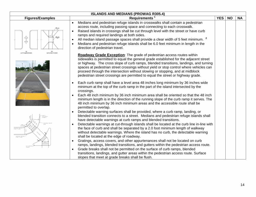
ISLANDS AND MEDIANS (PROWAG R305.4) Figures/Examples Requirements 1 YES NO NA
Medians and pedestrian refuge islands in crosswalks shall contain a pedestrian access route, including passing space and connecting to each crosswalk.
Raised islands in crossings shall be cut through level with the street or have curb ramps and required landings at both sides.
All median island passage spaces shall provide a clear width of 5 feet minimum. 2 Medians and pedestrian refuge islands shall be 6.0 feet minimum in length in the
direction of pedestrian travel. Roadway Grade Exception: The grade of pedestrian access routes within sidewalks is permitted to equal the general grade established for the adjacent street or highway. The cross slope of curb ramps, blended transitions, landings, and turning spaces at pedestrian street crossings without yield or stop control where vehicles can proceed through the intersection without slowing or stopping, and at midblock pedestrian street crossings are permitted to equal the street or highway grade.
Each curb ramp shall have a level area 48 inches long minimum by 36 inches wide minimum at the top of the curb ramp in the part of the island intersected by the crossings.
Each 48 inch minimum by 36 inch minimum area shall be oriented so that the 48 inch minimum length is in the direction of the running slope of the curb ramp it serves. The 48 inch minimum by 36 inch minimum areas and the accessible route shall be permitted to overlap.
Detectable warning surfaces shall be provided, where a curb ramp, landing, or blended transition connects to a street. Medians and pedestrian refuge islands shall have detectable warnings at curb ramps and blended transitions.
Detectable warnings at cut-through islands shall be located at the curb line in-line with the face of curb and shall be separated by a 2.0 foot minimum length of walkway without detectable warnings. Where the island has no curb, the detectable warning shall be located at the edge of roadway.
Gratings, access covers, and other appurtenances shall not be located on curb ramps, landings, blended transitions, and gutters within the pedestrian access route.
Grade breaks shall not be permitted on the surface of curb ramps, blended transitions, landings, and gutter areas within the pedestrian access route. Surface slopes that meet at grade breaks shall be flush.
15
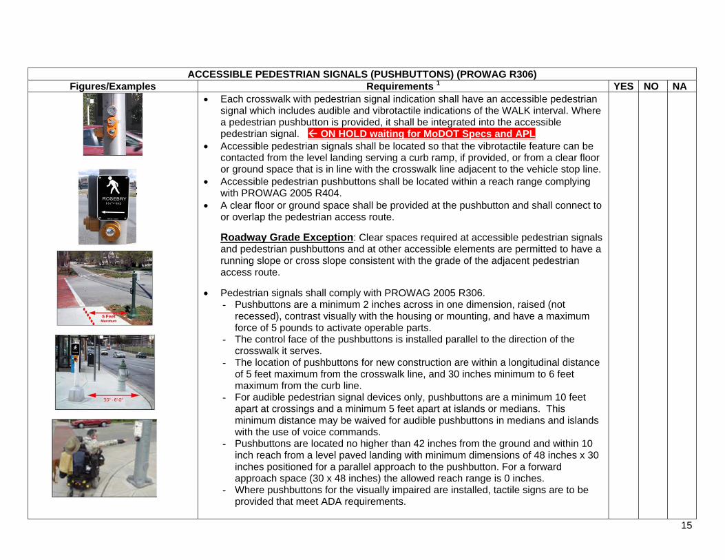
ACCESSIBLE PEDESTRIAN SIGNALS (PUSHBUTTONS) (PROWAG R306) Figures/Examples Requirements 1 YES NO NA
Each crosswalk with pedestrian signal indication shall have an accessible pedestrian signal which includes audible and vibrotactile indications of the WALK interval. Where a pedestrian pushbutton is provided, it shall be integrated into the accessible pedestrian signal. ON HOLD waiting for MoDOT Specs and APL
Accessible pedestrian signals shall be located so that the vibrotactile feature can be contacted from the level landing serving a curb ramp, if provided, or from a clear floor or ground space that is in line with the crosswalk line adjacent to the vehicle stop line.
Accessible pedestrian pushbuttons shall be located within a reach range complying with PROWAG 2005 R404.
A clear floor or ground space shall be provided at the pushbutton and shall connect to or overlap the pedestrian access route. Roadway Grade Exception: Clear spaces required at accessible pedestrian signals and pedestrian pushbuttons and at other accessible elements are permitted to have a running slope or cross slope consistent with the grade of the adjacent pedestrian access route.
Pedestrian signals shall comply with PROWAG 2005 R306. - Pushbuttons are a minimum 2 inches across in one dimension, raised (not
recessed), contrast visually with the housing or mounting, and have a maximum force of 5 pounds to activate operable parts.
- The control face of the pushbuttons is installed parallel to the direction of the crosswalk it serves.
- The location of pushbuttons for new construction are within a longitudinal distance of 5 feet maximum from the crosswalk line, and 30 inches minimum to 6 feet maximum from the curb line.
- For audible pedestrian signal devices only, pushbuttons are a minimum 10 feet apart at crossings and a minimum 5 feet apart at islands or medians. This minimum distance may be waived for audible pushbuttons in medians and islands with the use of voice commands.
- Pushbuttons are located no higher than 42 inches from the ground and within 10 inch reach from a level paved landing with minimum dimensions of 48 inches x 30 inches positioned for a parallel approach to the pushbutton. For a forward approach space (30 x 48 inches) the allowed reach range is 0 inches.
- Where pushbuttons for the visually impaired are installed, tactile signs are to be provided that meet ADA requirements.

16
PEDESTRIAN STREET CROSSINGS (PROWAG R305) Figures/Examples Requirements 1 YES NO NA
Crosswalks shall contain a pedestrian access route that connects to departure and arrival walkways through any median or pedestrian refuge island.
Marked crosswalks shall be 6 feet wide minimum. The grade of the pedestrian access route is permitted to equal the general grade
established for the adjacent street or highway, except that where pedestrian access routes are contained within pedestrian street crossings a maximum grade of 5 percent is required.
A 5 percent maximum cross slope is specified for pedestrian access routes contained within pedestrian street crossings without yield or stop control.
Crossings with Stop Control: The cross slope shall be 2 percent maximum. The cross slope at midblock crossings shall be permitted to be warped to meet street
or highway grade. The running slope shall be 5 percent maximum, measured parallel to the direction of
pedestrian travel in the crosswalk. Where pedestrian signals are provided at pedestrian street crossings, they shall
include accessible pedestrian signals and pedestrian pushbuttons complying with sections 4E.08 through 4E.13 of the MUTCD. Operable parts shall comply with R403. (2011 PROWAG R209.1) ON HOLD waiting for MoDOT Specs and APL
Crosswalk pavement marking is 6 inches wide white. Stop bar is at minimum 4 feet from the crosswalk. Curb ramps at marked crossings shall be wholly contained within the markings,
excluding any flared sides. Gratings, access covers, and other appurtenances shall not be located on curb
ramps, landings, blended transitions, and gutters within the pedestrian access route. Grade breaks shall not be permitted on the surface of curb ramps, blended
transitions, landings, and gutter areas within the pedestrian access route. Surface slopes that meet at grade breaks shall be flush.
Beyond the curb face, a clear space of 4.0 feet minimum by 4.0 feet minimum shall be provided within the width of the crosswalk and wholly outside the parallel vehicle travel lane.

17
ALTERNATE CIRCULATION PATH (PROWAG R302) Figures/Examples Requirements 1 YES NO NA
Alternate circulation paths shall contain a pedestrian access route. To the maximum extent feasible, the alternate circulation path shall be provided on
the same side of the street as the disrupted route. Where the alternate circulation path is exposed to adjacent construction, excavation
drop-offs, traffic, or other hazards, it shall be protected with a pedestrian barricade or channelizing device complying with MUTCD 6F-58, 6F-63, and 6F-66.
Pedestrian barricades and channelizing devices shall be continuous, stable, and non-flexible and shall consist of a wall, fence, or enclosures specified in section 6F-58, 6F-63, and 6F-66 of the MUTCD (incorporated by reference; see PROWAG 2005 R104.2.4).
A detectable continuous bottom edge shall be provided 2 inches maximum above the ground or walkway surface.
Devices shall provide a continuous surface or upper rail at 3.0 feet minimum above the ground or walkway surface.
Support members shall not protrude into the alternate circulation path.
BUS BOARDING AND ALIGHTING AREAS (PROWAG R410)
Figures/Examples Requirements 1 YES NO NA
Bus stop boarding and alighting areas shall have a firm, stable surface. Bus stop boarding and alighting areas shall provide a clear length of 8 feet minimum,
measured perpendicular to the curb or vehicle roadway edge, and a clear width of 5 feet minimum, measured parallel to the vehicle roadway.
Bus stop boarding and alighting areas shall be connected to streets, sidewalks, or pedestrian paths by an accessible route.
Parallel to the roadway, the slope of the bus stop boarding and alighting area shall be the same as the roadway, to the maximum extent practicable. Perpendicular to the roadway, the slope of the bus stop boarding and alighting area shall not be steeper than2 percent.
Bus shelters shall provide a minimum 30 inch by 48 inch clear floor or ground space entirely within the shelter.
Bus shelters shall be connected by an accessible route to a boarding and alighting area.
18
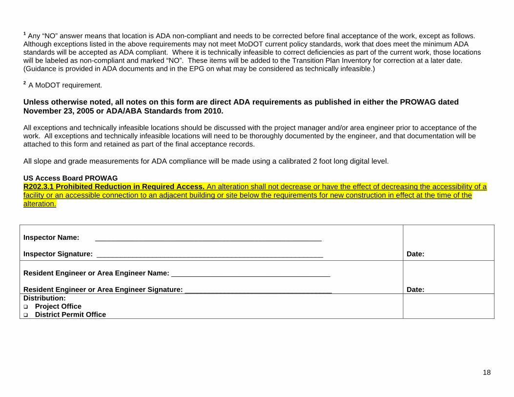
1 Any “NO” answer means that location is ADA non-compliant and needs to be corrected before final acceptance of the work, except as follows. Although exceptions listed in the above requirements may not meet MoDOT current policy standards, work that does meet the minimum ADA standards will be accepted as ADA compliant. Where it is technically infeasible to correct deficiencies as part of the current work, those locations will be labeled as non-compliant and marked “NO”. These items will be added to the Transition Plan Inventory for correction at a later date. (Guidance is provided in ADA documents and in the EPG on what may be considered as technically infeasible.) 2 A MoDOT requirement. Unless otherwise noted, all notes on this form are direct ADA requirements as published in either the PROWAG dated November 23, 2005 or ADA/ABA Standards from 2010. All exceptions and technically infeasible locations should be discussed with the project manager and/or area engineer prior to acceptance of the work. All exceptions and technically infeasible locations will need to be thoroughly documented by the engineer, and that documentation will be attached to this form and retained as part of the final acceptance records. All slope and grade measurements for ADA compliance will be made using a calibrated 2 foot long digital level. US Access Board PROWAG R202.3.1 Prohibited Reduction in Required Access. An alteration shall not decrease or have the effect of decreasing the accessibility of a facility or an accessible connection to an adjacent building or site below the requirements for new construction in effect at the time of the alteration. Inspector Name: _________________________________________________________ Inspector Signature: _________________________________________________________
Date:
Resident Engineer or Area Engineer Name: ________________________________________ Resident Engineer or Area Engineer Signature: _____________________________________
Date:
Distribution: Project Office District Permit Office

19
SAMPLE ADA EXCEPTIONS DOCUMENTATION
Job No. __________ Route ___________ County ________________ Location________________________________________ Item Location Standard As Built Discussion Sidewalk Width Third Street Sta 3+00 to 7+00 RT 5’ wide Exist 3’ wide Required 5’ x 5’ Passing Space added at 5+00 Curb Ramp Grade SE Quad of Main & First 8.33% 11.2% As-built Curb Ramp is 16.0’ long Parallel Ramp Sta 35+20 to 35+25 Rt Rte 14 Landing running grade (turning space) 2.00% 2.6% Landing running grade matches existing roadway grade Sidewalk Grade Sta 23+45 to 23+52 5.0% 8.4% Match existing floor at two exist doorways,
Straight grade between fixed elevations Inspector Name: _________________________________________________________ Inspector Signature: _________________________________________________________
Date:
Resident Engineer or Area Engineer Name: ________________________________________ Resident Engineer or Area Engineer Signature: _____________________________________
Date:
Distribution: Project Office District Permit Office
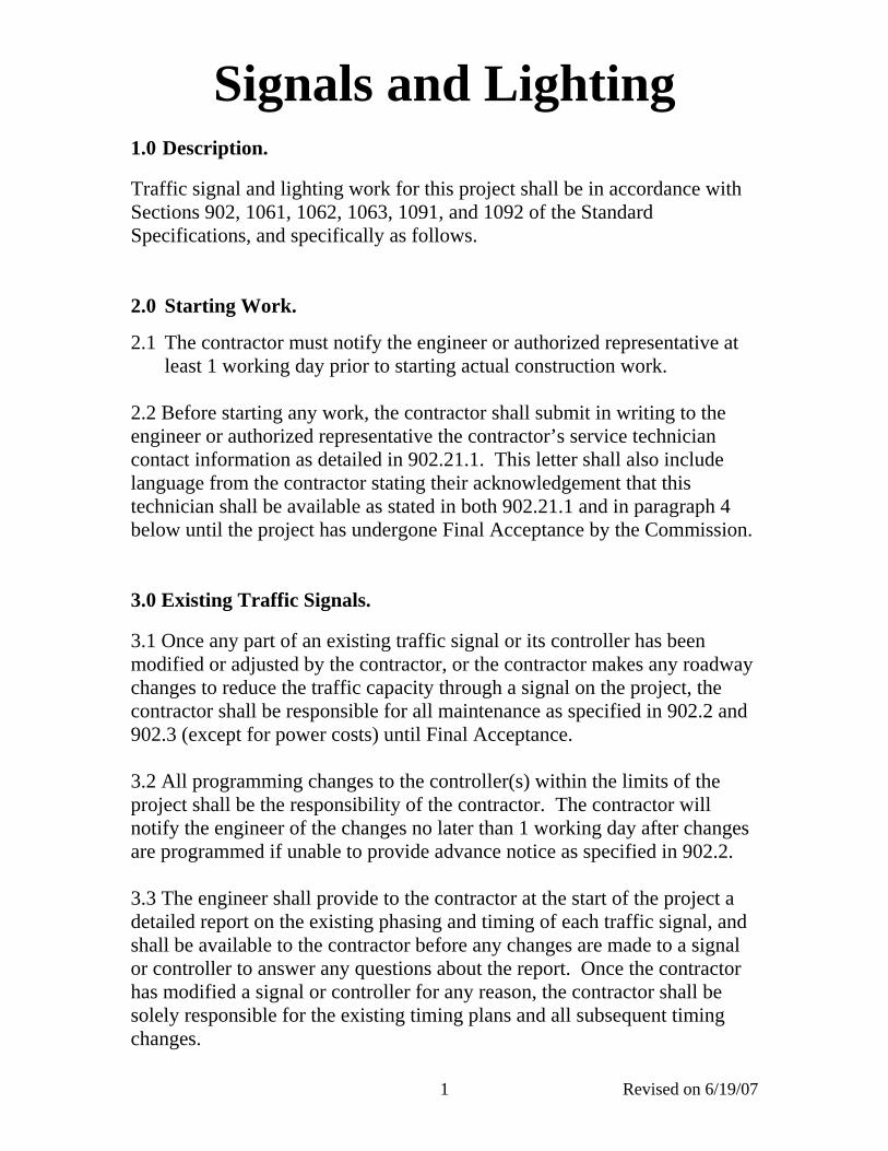
Signals and Lighting
1 Revised on 6/19/07
1.0 Description.
Traffic signal and lighting work for this project shall be in accordance with Sections 902, 1061, 1062, 1063, 1091, and 1092 of the Standard Specifications, and specifically as follows. 2.0 Starting Work.
2.1 The contractor must notify the engineer or authorized representative at least 1 working day prior to starting actual construction work.
2.2 Before starting any work, the contractor shall submit in writing to the engineer or authorized representative the contractor’s service technician contact information as detailed in 902.21.1. This letter shall also include language from the contractor stating their acknowledgement that this technician shall be available as stated in both 902.21.1 and in paragraph 4 below until the project has undergone Final Acceptance by the Commission. 3.0 Existing Traffic Signals.
3.1 Once any part of an existing traffic signal or its controller has been modified or adjusted by the contractor, or the contractor makes any roadway changes to reduce the traffic capacity through a signal on the project, the contractor shall be responsible for all maintenance as specified in 902.2 and 902.3 (except for power costs) until Final Acceptance. 3.2 All programming changes to the controller(s) within the limits of the project shall be the responsibility of the contractor. The contractor will notify the engineer of the changes no later than 1 working day after changes are programmed if unable to provide advance notice as specified in 902.2. 3.3 The engineer shall provide to the contractor at the start of the project a detailed report on the existing phasing and timing of each traffic signal, and shall be available to the contractor before any changes are made to a signal or controller to answer any questions about the report. Once the contractor has modified a signal or controller for any reason, the contractor shall be solely responsible for the existing timing plans and all subsequent timing changes.

3.4 All modifications to existing signal equipment not detailed in the plans to make it compatible with the proposed signal work is to be performed by the applicant's contractor only after they receive written approval of these modification by the engineer or authorized representative. 4.0 Existing Traffic Signal Maintenance and Response.
Once a signal has been modified as noted in paragraph 3.0 above, the contractor shall respond to any signal timing complaints or malfunction complaints as specified in 902.21.1. Response time shall be 1 hour for complaints received by the engineer between 6 AM and 6 PM on non-holiday weekdays, and 2 hours for all other times. For some cases (due to travel times or other extenuating circumstances) additional time may be acceptable within reason, but must be approved by the engineer. These timeframes will replace the '24 hour' response time in Section 105.14 for any signal-related incidents, where the entire cost of the work, if performed by MoDOT personnel or a third party, will be computed as described in Sec 108.9 and deducted from the payments due the contractor. 5.0 New Traffic Signal Equipment and Test Periods.
5.1 In order to satisfy the provisions of 902.2, the contractor shall, at least 5 working days prior to possible activation, request in writing to the engineer a list of new equipment which will be ready for operation and a proposed start date of the 15-day test period. This date will not be authorized until all signal work has been completed and approved by the engineer. 5.2 No signal will be turned on to full operation prior to the signing and striping being in place and turn on approval being given by the engineer or authorized representative. 5.3 Upon experiencing any failure or malfunction, the 15-day test period will be terminated. The 15-day test period will start over at day one (1) once the malfunction or failure has been corrected to the satisfaction of the engineer. 2 Revised on 6/19/07
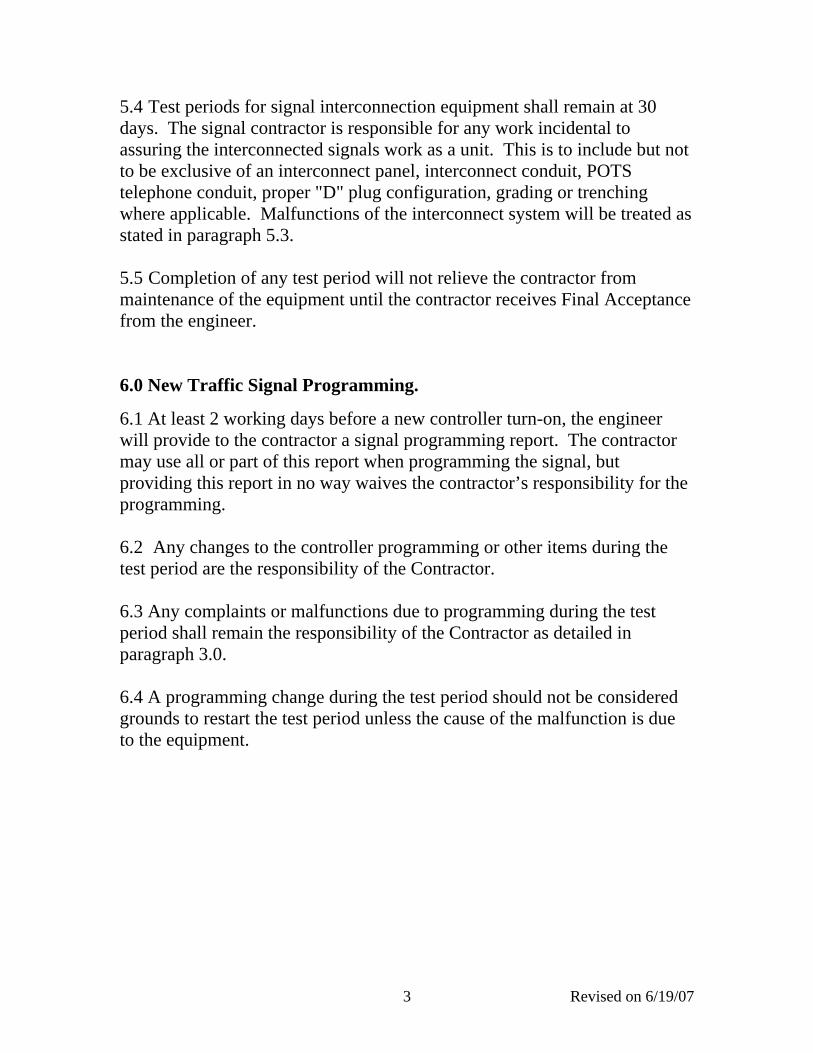
5.4 Test periods for signal interconnection equipment shall remain at 30 days. The signal contractor is responsible for any work incidental to assuring the interconnected signals work as a unit. This is to include but not to be exclusive of an interconnect panel, interconnect conduit, POTS telephone conduit, proper "D" plug configuration, grading or trenching where applicable. Malfunctions of the interconnect system will be treated as stated in paragraph 5.3. 5.5 Completion of any test period will not relieve the contractor from maintenance of the equipment until the contractor receives Final Acceptance from the engineer. 6.0 New Traffic Signal Programming.
6.1 At least 2 working days before a new controller turn-on, the engineer will provide to the contractor a signal programming report. The contractor may use all or part of this report when programming the signal, but providing this report in no way waives the contractor’s responsibility for the programming. 6.2 Any changes to the controller programming or other items during the test period are the responsibility of the Contractor. 6.3 Any complaints or malfunctions due to programming during the test period shall remain the responsibility of the Contractor as detailed in paragraph 3.0. 6.4 A programming change during the test period should not be considered grounds to restart the test period unless the cause of the malfunction is due to the equipment.
3 Revised on 6/19/07
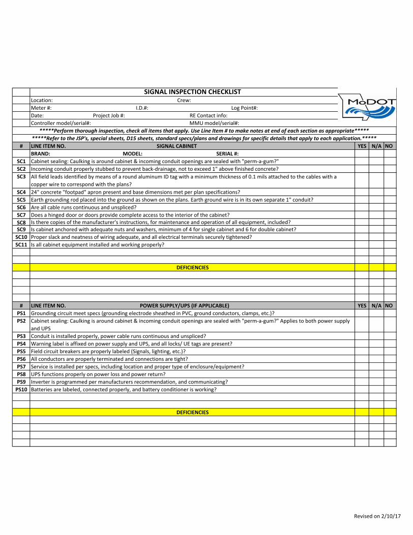
SIGNAL INSPECTION CHECKLIST
# LINE ITEM NO. SIGNAL CABINET YES N/A NO
BRAND: MODEL: SERIAL #:
SC1 Cabinet sealing: Caulking is around cabinet & incoming conduit openings are sealed with "perm‐a‐gum?"
SC2 Incoming conduit properly stubbed to prevent back‐drainage, not to exceed 1" above finished concrete?
SC3 All field leads identified by means of a round aluminum ID tag with a minimum thickness of 0.1 mils attached to the cables with a
copper wire to correspond with the plans?
SC4 24" concrete "footpad" apron present and base dimensions met per plan specifications?
SC5 Earth grounding rod placed into the ground as shown on the plans. Earth ground wire is in its own separate 1" conduit?
SC6 Are all cable runs continuous and unspliced?
SC7 Does a hinged door or doors provide complete access to the interior of the cabinet?
SC8 Is there copies of the manufacturer's instructions, for maintenance and operation of all equipment, included?SC9 Is cabinet anchored with adequate nuts and washers, minimum of 4 for single cabinet and 6 for double cabinet?
SC10 Proper slack and neatness of wiring adequate, and all electrical terminals securely tightened?
SC11 Is all cabinet equipment installed and working properly?
DEFICIENCIES
# LINE ITEM NO. POWER SUPPLY/UPS (IF APPLICABLE) YES N/A NO
PS1 Grounding circuit meet specs (grounding electrode sheathed in PVC, ground conductors, clamps, etc.)?
PS2 Cabinet sealing: Caulking is around cabinet & incoming conduit openings are sealed with "perm‐a‐gum?" Applies to both power supply
and UPS
PS3 Conduit is installed properly, power cable runs continuous and unspliced?
PS4 Warning label is affixed on power supply and UPS, and all locks/ UE tags are present?
PS5 Field circuit breakers are properly labeled (Signals, lighting, etc.)?
PS6 All conductors are properly terminated and connections are tight?
PS7 Service is installed per specs, including location and proper type of enclosure/equipment?
PS8 UPS functions properly on power loss and power return?
PS9 Inverter is programmed per manufacturers recommendation, and communicating?
PS10 Batteries are labeled, connected properly, and battery conditioner is working?
DEFICIENCIES
*****Refer to the JSP's, special sheets, D15 sheets, standard specs/plans and drawings for specific details that apply to each application.*****
Controller model/serial#: MMU model/serial#:
Date: Project Job #: RE Contact info:
Meter #: I.D.#: Log Point#:
Location: Crew:
*****Perform thorough inspection, check all items that apply. Use Line Item # to make notes at end of each section as appropriate*****
Revised on 2/10/17
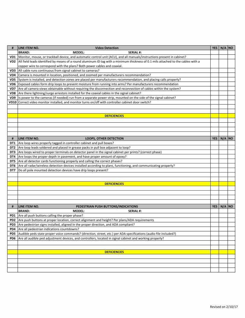
# LINE ITEM NO. Video Detection YES N/A NO
BRAND: MODEL: SERIAL #:
VD1 Monitor, mouse, or trackball device, and automatic control unit (ACU), and all manuals/instructions present in cabinet?
VD2 All field leads identified by means of a round aluminum ID tag with a minimum thickness of 0.1 mils attached to the cables with a
copper wire to correspond with the plans? Both power cables and coaxial.
VD3 All cable runs continuous from signal cabinet to cameras?
VD4 Camera is mounted in location, positioned, and zoomed per manufacturers recommendation?
VD5 System is installed, and detection zones are placed per manufacturers recommendation, and placing calls properly?
VD6 Exposed cables form drip loops to prevent moisture from running into arms? Per manufacturers recommendation
VD7 Are all camera views obtainable without requiring the disconnection and reconnection of cables within the system?
VD8 Are there lightning/surge arrestors installed for the coaxial cables in the signal cabinet?
VD9 Is power to the cameras (if needed) run from a separate power strip, mounted on the side of the signal cabinet?
VD10 Correct video monitor installed, and monitor turns on/off with controller cabinet door switch?
DEFICIENCIES
# LINE ITEM NO. LOOPS, OTHER DETECTION YES N/A NO
DT1 Are loop wires properly tagged in controller cabinet and pull boxes?
DT2 Are loop leads soldered and placed in grease packs in pull box adjacent to loop?
DT3 Are loops wired to proper terminals on detector panel in the signal cabinet per prints? (correct phase)
DT4 Are loops the proper depth in pavement, and have proper amount of epoxy?
DT5 Are all detector cards functioning properly and calling the correct phases?
DT6 Are all radar/wireless detection devices installed according to plans, functioning, and communicating properly?
DT7 Do all pole mounted detection devices have drip loops present?
DEFICIENCIES
# LINE ITEM NO. PEDESTRIAN PUSH BUTTONS/INDICATIONS YES N/A NO
BRAND: MODEL: SERIAL #:
PD1 Are all push buttons calling the proper phase?
PD2 Are push buttons at proper location, correct alignment and height? Per plans/ADA requirements
PD3 Are pedestrian signs installed, aligned in the proper direction, and ADA compliant?
PD4 Are all pedestrian indications countdowns?
PD5 Audible peds state proper voice commands? (direction, street, etc.) per ADA specifications (audio file included?)
PD6 Are all audible ped adjustment devices, and controllers, located in signal cabinet and working properly?
DEFICIENCIES
Revised on 2/10/17

# LINE ITEM NO. PULL BOXES YES N/A NO
PB1Conduit enters pull box a minimum of 2" and a maximum of 4" and hole shall not have a gap around conduit more than 1/2"?
PB2 All pull boxes have proper lids (labeled) and Penta head bolts?
PB3 Threaded hole that receives the cover lock‐down bolt, shall be open at the bottom to allow the cleanout of debris?
PB4 Ground bonding conductors and/or grounding rods and clamps are properly installed?
PB5 Slack in each cable is provided by a 6‐foot loop coiled in each pull box (hung and secured on J‐hook) and a 3‐foot loop coiled in each
junction box?PB6 All field leads identified by means of a round aluminum ID tag with a minimum thickness of 0.1 mils attached to the cables with a
copper wire to correspond with the plans?
PB7 Pull boxes are free of cracks/damage? Free from concrete slurry, dirt & debris?
PB8 Pull box installed per plans, is flush with surfaced area and approx. 1" above earth?
PB9 Drains for pull boxes constructed as shown on the plans, and drain properly?
PB10 General site cleanup, finish grading, and seeding performed. Concrete forms removed?
DEFICIENCIES
# LINE ITEM NO. SIGNAL POLES/STRUCTURES YES N/A NO
SP1 Are proper ground connections to uprights & posts, with 6 AWG stranded copper wire, installed?
SP2 Do upright base bolts have cover plates in place, screen, and proper weep holes installed?
SP3 Are cover plates installed on top of uprights, on mast arm ends, and on upright hand‐hole covers?
SP4 Signal uprights, arms, and structures mounted correctly? And correct sizes?
SP5 Does wire have any cuts, scrapes, splices, kinks, etc..?
SP6 Is proper signing present, and mounted and aligned properly? For all lanes and walks.
DEFICIENCIES
Revised on 2/10/17

# LINE ITEM NO. SIGNAL HEADS/INDICATIONS YES N/A NO
SH1 Are all signal indications illuminated with proper LED modules?
SH2 Are signal/pedestrian heads installed properly, with the correct hardware/alignment? (Entire assembly of head including indication) per
plans.
SH3 Are signal/pedestrian heads installed to the correct height? (ADA requirements)
SH4 Are gaskets in signal heads in place, and are heads tight?
SH5 Visors, louvers, and programmable heads properly aligned with appropriate lane?
SH6 In signal heads and splice boxes, is there proper slack and is the neatness of wiring adequate. Are all electrical terminals securely
tightened?
DEFICIENCIES
# LINE ITEM NO. FIBER/INTERCONNECT YES N/A NO
FB1 At each pull box and signal cabinet, the interconnect cable shall be visibly marked "Caution‐Fiber Optic Cable" by self‐adhesive
weatherproof tags.
FB2 Each pull box adjacent to a signal cabinet or a splice cabinet shall contain a minimum of 60 feet of coiled cable. Mid‐block pull boxes
shall contain a minimum of 10 feet of coiled cable. Stored cable shall be neatly coiled as per the manufacturer's minimum bending
radius specification. Where the size of the box precludes the coiling of cable above the minimum bend radius, the cable shall pass
straight through the pull box.
FB3Fiber optic interconnect cable shall be installed in continuous runs for each system, in conduit, pull boxes, splice cabinets or traffic
signal controller cabinets. Splices outside of the splice cabinets or controller cabinets will not be permitted.
DEFICIENCES
# LINE ITEM NO. GENERAL
G1 All equipment is on the APL (Approved Products List)?
G2 Old service, structures, cabinet, conduits, and equipment removed?
G3 Is all equipment as installed, the same as projected on the D15 sheet?
G4 If job states control modules for video, audible peds and ESB heads are to be provided, ensure correct # of units are provided
DEFICIENCES
Revised on 2/10/17
Revised 2/10/17
LIGHTING INSPECTION CHECK LIST FORM REV. 2-2017
Job No. Electrical Contractor: MoDOT RE:
LOCATION:
REVIEWED BY:
DATE REVIEWED
METER #
VOLTAGE:
TYPE OF CONTROL…(circle one) 30 AMP …..100 AMP Multi Circuit….100 AMP Multi Circuit Pad
Mount WATTAGE:
TYPE H.P.S.
or M.H. POLE TYPE / MOUNTING DESIGN:
MOUNTING HEIGHT
BREAKER #1 (meg ohms)
BREAKER #2 (meg ohms)
BREAKER #3 (meg ohms)
/ BREAKER #4 (meg ohms)
/
***REFER TO THE JSP’S, D-15 SHEETS, SPECIAL SHEETS, STANDARD PLANS AND DRAWINGS FOR SPECIFIC DETAILS THAT APPLY TO EACH APPLICATION***
SECTIONS 707, 901, 902, 1060, 1061, 1062, 1091, 1092 Perform thorough inspection, check of all items that apply. Use Line Item # to make notes on attached “DEFICIENCIES” sheet.
YES NO
CHECK CABINET FOR THE FOLLOWING: INSTALLATION CONFORMS TO STD. PLANS CC-1 Caulking is around cabinet and Incoming conduit openings are sealed with pliable putty
CC-2 Incoming conduit properly stubbed above cabinet floor to prevent back-drainage, not to exceed 1” above finished concrete?
CC-3 All field leads shall be identified by means of a round aluminum ID tag CC-4 Concrete “footpad” Apron present and Base Dimensions met per Plan Spec’s? CC-5 Cabinet Grounding circuit CC-6 Photo control is time delay CC-7 All Cabinet equipment installed and working properly? All equipment is on the Traffic A.P.L. CC-8 I.D. Labels are installed CC-9 Ground is at final grade CC-10 Circuits pass 10 meg ohm min test
DEFICIENCIES
Revised 2/10/17
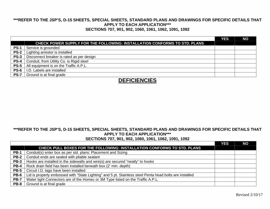
***REFER TO THE JSP’S, D-15 SHEETS, SPECIAL SHEETS, STANDARD PLANS AND DRAWINGS FOR SPECIFIC DETAILS THAT APPLY TO EACH APPLICATION***
SECTIONS 707, 901, 902, 1060, 1061, 1062, 1091, 1092
YES NO CHECK POWER SUPPLY FOR THE FOLLOWING: INSTALLATION CONFORMS TO STD. PLANS
PS-1 Service is grounded PS-2 Lighting arrestor is installed PS-3 Disconnect breaker is rated as per design PS-4 Conduit, from Utility Co. is Rigid steel PS-5 All equipment is on the Traffic A.P.L. PS-6 I.D. Labels are installed PS-7 Ground is at final grade
DEFICIENCIES
***REFER TO THE JSP’S, D-15 SHEETS, SPECIAL SHEETS, STANDARD PLANS AND DRAWINGS FOR SPECIFIC DETAILS THAT APPLY TO EACH APPLICATION***
SECTIONS 707, 901, 902, 1060, 1061, 1062, 1091, 1092 YES NO
CHECK PULL BOXES FOR THE FOLLOWING: INSTALLATION CONFORMS TO STD. PLANS PB-1 Conduit(s) enter box as per std. plans: Placement and Sizing PB-2 Conduit ends are sealed with pliable sealant PB-3 Hooks are installed in the sidewalls and wire(s) are secured “neatly” to hooks PB-4 Rock drain field has been installed beneath box (2’ min. depth) PB-5 Circuit I.D. tags have been installed PB-6 Lid is properly embossed with “State Lighting” and 5 pt. Stainless steel Penta head bolts are installed PB-7 Water tight Connectors are of the Homec or 3M Type listed on the Traffic A.P.L. PB-8 Ground is at final grade

Revised 2/10/17
DEFICIENCIES
***REFER TO THE JSP’S, D-15 SHEETS, SPECIAL SHEETS, STANDARD PLANS AND DRAWINGS FOR SPECIFIC DETAILS THAT APPLY TO EACH APPLICATION***
SECTIONS 707, 901, 902, 1060, 1061, 1062, 1091, 1092 YES NO
CHECK POLES FOR THE FOLLOWING: INSTALLATION CONFORMS TO STD. PLANS LP-1 Conduit(s) extend min. 6” above the foundation plate LP-2 Conduit ends are sealed with pliable sealant LP-3 Ground(s) are attached to the “Transformer Base” grounding lug LP-4 Access door is installed, hinged and has “Warning High Voltage” label or embossed LP-5 Fused disconnect devices have been installed LP-6 Lock & Flat washers have been used for all attachments LP-7 Bolt covers have been installed (external) at the Pole to Base connection LP-8 Cap has been installed at top of pole LP-9 Luminaires work and are correct type and proper angle (glass globe, wattage, design) Listed on the Traffic A.P.L.
LP-10 Ground is at final grade DEFICIENCIES
***REFER TO THE JSP’S, D-15 SHEETS, SPECIAL SHEETS, STANDARD PLANS AND DRAWINGS FOR SPECIFIC DETAILS THAT APPLY TO EACH APPLICATION***
SECTIONS 707, 901, 902, 1060, 1061, 1062, 1091, 1092 YES NO
CHECK UNDERPASS FOR THE FOLLOWING: INSTALLATION CONFORMS TO STD. PLANS UP-1 Conduit(s) are secured properly (max hanger spacing) UP-2 Conduit have weep holes to remove moisture UP-3 Ground(s) are attached UP-4 Fixture is correct type (glass globe, wattage, design) Listed on the Traffic A.P.L. UP-5 Fused disconnect devices have been installed when specified
Revised 2/10/17
UP-6 Lock & Flat washers have been used for all attachments DEFICIENCIES

Meter #
Date: Log Mile #
# LINE ITEM No. CABINET Yes N/A NOC1C2C3C4C5C6C7C8C9
# LINE ITEM No. PULL BOXES Yes N/A NOPB1
PB2PB3PB4
PB5PB6
PB7
PB8PB9
PB10
# LINE ITEM No. POWER SUPPLY Yes N/A NOPS1PS2
PS3PS4PS5PS6PS7PS8PS9
# LINE ITEM No. ITS POLES / STRUCTURES Yes N/A NOST1ST2ST3ST4ST5ST6ST7ST8ST9
# LINE ITEM No. GENERAL Yes N/A NOG1 All equipment on APL (Approved Products List)
Gateway Guide logo installed on the pole of the DMS structure.
Perform thorough inspection, check all items that apply. Use Line Item # to make notes at end of document as appropriate.
Network Radio installed per specifications.
All electrical terminals securely tightened.
Proper Ground Connections to Uprights & Poles with 6 AWG stranded copper? Air terminal installed where applicable.Upright Base Bolts have cover plates in place where applicable and rodent screen installed.All hand-hole covers, pipe plugs, and pole top cover are in place?
Fiber optic cables secured to pull box hangers with the required amount of slack. (30' in intermediate pull boxes, 60' in pull boxes adjacent to a cabinet, or other length as specified in plans.)Locator wire (trace wire) has been installed in all non-metallic underground conduits. Jacketed .10" THHN.General site cleanup, finish grading, and seeding performed. Concrete forms removed.MoDOT Buried Cable Drivable Delineator Post Installed next to pull box and along fiber run per spec.
Field Circuit Breakers properly labeled. (CCTV, DMS, RTMS, Signal, etc.)Power supply door properly label "ITS Disconnect" "Signal Disconnect" per application.
Concrete “footpad” Apron present and Base Dimensions met per Plan Spec’s.Cabinet Grounding Circuit properly installed.
RTMS installed per specifications.CCTV installed per specificationsDMS installed and oriented per specifications.
Service is grounded properly?Conduit is installed properly, power cable runs shall be continuous and unspliced from the power supply to the Utility disconnect.Silicone caulk installed between cabinet and footing. Conduit openings are sealed with “perm-a-gum.
Pull ropes installed in all empty conduit cells and textile innerducts. Pull ropes shall be polypropylene with a minimum tensile strength of 600 pounds.
Conduit Shall enter pull box minimum of 2” and maximum of 4” and hole shall not have a gap around conduit more than ½”. The conduit containing only fiber optic cable shall be PVC or high density PE Conduit in accordance with Sec 1060 and shall be orange in color.All Pull Boxes have proper lids (labeled) and Penta head bolts?
Ground Bonding Conductors and/or Ground Rods and clamps properly installed? Proper cad welded connections as needed.
ITS Pull Box installed, shall be flush with surface area and Class 2 and 5 have concrete apron installed.
Drains for pull boxes shall be constructed as shown on the plans? and drain properly.
Concrete “footpad” Apron present and Base Dimensions met per Plan Spec’s.Debris and metal drill shavings from inside of cabinets has been removed.Cabinet Grounding Circuit properly installed.Fiber optic cables and jumpers mounted securely and neatly in cabinet and splice enclosures.All electrical terminals securely tightened.
ITS PUNCH LIST FORM (SL District) Location:Unit/Crew:
Project Job #
UPS System installed and operating per specifications.
RE Office Contact:________________________
Solar Power System installed per specifications.
CAB Sealing: Caulking is around cabinet & Incoming conduit openings are sealed with “perm-a-gum?” Incoming conduit properly stubbed to prevent back-drainage, not to exceed 1” above finished concrete?All ITS equipment installed, online, and working properly.All field leads shall be labeled.
Continued on Back Revised 2/10/17
G2G3
Old service, structures, cabinet, conduits and equipment removedSite restored to its original condition any disturbed areas at sites including, but not limited to, pull box, conduit and pole base installations.
DEFICIENCIES AND COMMENTS ATTACHED
Revised 2/10/17

Outsource Inspector Evaluation Form
Evaluation Done By MoDOT Permit Inspector, ______________________________Date: __________
Inspector (name/company): ___________________________________________________________ Address/Phone #: ___________________________________________________________ Permit # / Project Name: ______________________________________ Rte/Co: _______________ 1) Preconstruction Meeting
Did the Outsource Inspector attend the meeting(s)? yes no Was the Outsource Inspector given the Outsource Inspection packet? yes no
2) Daily Reports
Were the reports completed with adequate information? yes no Were the reports received within 48 hours? yes no
3) Test Results
Were there any failing tests? yes no If yes, how were they resolved?_________________ _______________________________________________________________________________ Were the test results received within 48 hours? yes no
4) Questions pertaining to Project
Did the Outsource Inspector ask the questions? yes no If no, who?___________________ Could the answers have been easily found in spec book? yes no
5) Traffic Control
Was the lane closure request sent in? yes no Were there any problems with the traffic control? yes no
6) Signals and Lighting
Were there any complaints from the signal shop? yes no n/a Were there any complaints from the lighting shop? yes no n/a
7) Final Inspection
Did the Outsource Inspector conduct a semi-final inspection and do a punchlist? yes no Did the Outsource Inspector attend the final inspection? yes no
8) Recommendation
Would you recommend this inspector for future outsource inspection? yes no Why or Why Not? _______________________________________________________________ _______________________________________________________________________________ _______________________________________________________________________________ _______________________________________________________________________________ _____________________________________________________________________________________________________________________________________________________________________________________________________________________________________________
** If any no’s are checked, please explain on the back of this sheet and attach supporting documentation