Embed Size (px)
Citation preview
1 Copyright © 2013 by ASME
ASME 2013 7th International Conference on Energy Sustainability & 11th Fuel Cell Science, Engineering and Technology Conference
ES-FuelCell2013 July 14-19, 2013, Minneapolis, MN, USA
ES-FuelCell2013-18311
INVELOX: A NEW CONCEPT IN WIND ENERGY HARVESTING
Daryoush Allaei SheerWind, Inc.
Chaska, Minnesota, USA
Yiannis Andreopoulos City College of New York
New York, New York,
ABSTRACT The results of multi physics simulations involving
Computational Fluid Dynamics, used to evaluate a highly acclaimed innovative wind power generation system known as INVELOX, are presented. This patented technology significantly outperforms traditional wind turbines of the same diameter and aerodynamic characteristics under the same wind conditions and it delivers superior power output, at reduced cost. Furthermore, INVELOX solves all the major issues, such as low turbine reliability, intermittency issues and adverse environmental and radar impact that have so far undermined the wind industry. The innovative features of the INVELOX system are presented. First, it eliminates the need for tower-mounted turbines. These large, mechanically complex turbines, and the enormous towers used to hoist them into the sky, are the hallmark of today’s wind power industry. They are also expensive, unwieldy, inefficient, and hazardous to people and wildlife. The second innovative feature of INVELOX is that it captures wind flow through an omnidirectional intake and thereby there is no need for a passive or active yaw control. Third, it accelerates the flow within a shrouded Venturi section. Simulating the performance of this wind delivery system is quite challenging because of the complexity of the wind delivery system and its interaction with wind at the front end and with a turbine at the back end. One requires acceptable computational results used to design the INVELOX system based on the model predicted performance. The goals is to better model and understand the flow field inside the INVELOX where the actual wind turbine is located as well the external flow field which not only provides the intake flow but also has to match the exhaust flow of the system. The present computations involved cases with different incoming wind directions and changes in the intake geometry. The results are compared with those obtained by using another commercially available CFD package. Both velocity and pressure fields are compared in this analysis. Both packages show that it is possible to capture, accelerate and concentrate the wind.
Increased wind velocities result in significant improvement in the power output. These results led to the design of a demonstration unit briefly presented in this paper.
INTRODUCTION Wind energy conversion systems have more than 2000-
year history. Initially, wind energy was used to induce a function, such as moving boats using sail, cooling houses by circulating outside air, running machinery in farms, and even small production facilities. In late 1800s and early 1900s, conversion of wind energy to electrical power marked a turning point for the wind power generation industry. Due to energy crisis and changes in the political and social climates, wind turbines started to rapidly spread across the globe in the last three decades. However, wind power is far from its full potential.
Manufacturers have incrementally improved conventional wind turbines in the last two decades – but the greatest energy output gains have come from building turbines with ever-larger blades, perched on ever-taller towers, built at ever increasing expense and with ever increasing areas of land required. As the size and height of turbines and towers increase, often reaching beyond 100 meters – wide enough to allow one or two 747 aircrafts to fit within the sweep area of the blades – the cost of wind-generated power continues to exceed the cost of power generated by hydropower plants, coal and natural gas. Turbines are often subjected to excessive downtime, and failure and repair costs are high. Moreover, complaints of harm to wildlife continue to plague the industry, as do complaints of harm to human health from high-decibel low-frequency sound waves from wind turbines, propeller noise and flickering of light through rotating turbines.
The visual nuisances of large wind farms are another cause of complaints. Most alarming is the increase in the number of unhappy investors and financial institutions funding utility
2 Copyright © 2013 by ASME
scale wind power plants in recent years, because they do not believe their initial investment will ever be recovered.
Conversion of wind power to electrical energy is controlled by two major factors: free-stream wind speed and blade radius. Because of these two design parameters, the tower height and blade sizes in conventional systems have grown to be massive. In terms of manufacturing, logistics, installation and maintenance challenges and costs, the heights of the towers and size of the blades are reaching to very challenging limits.
In recent years, innovators across [1-15] the globe have developed approaches showing promise for certain applications. For example, airborne units have been developed with turbines at 300 to 500 meters above the ground. A variety of single and multiple array ducted turbines [1-3, 12-15] have also been developed. The single-ducted turbines have been shown to be effective and economical for small wind applications. Attempts have been made to scale up the single-ducted turbines for utility scale applications. However, due to the required excessive size of the shroud as the turbines grow in size, and the required speed increase, they have been proven to be uneconomical. Even though an array of ducted turbines can generate more electrical energy, they suffer from complexity in actual implementation for utility scale. As a result, the industry has remained on the same track – using turbines mounted on the top of towers – for almost a century.
In order to make wind power an acceptable mainstream electrical energy generation industry, a totally game-changing approach, with disruptive features, needs to be developed. Such a disruptive approach and way of thinking, with no doubt initially and naturally, will generate huge resistance and opposition from current experts in the industry.
A recently developed technology [4-11], INVELOX (increased velocity), has shown promise. The patented [10-11] INVELOX is simply a wind capturing and delivery system that allows more engineering control than ever before. While conventional wind turbines use massive turbine-generator systems mounted on top of a tower, INVELOX, by contrast, funnels wind energy to ground-based generators. Instead of snatching bits of energy from the wind as it passes through the blades of a rotor, the INVELOX technology captures wind with a funnel and directs it through a tapering passageway that passively and naturally accelerates its flow. This stream of kinetic energy then drives a generator that is installed safely and economically at ground or sub-ground level.
Even though the original idea of capturing and accelerating wind is based on a 100-year-old ducted turbine combining both Bernoulli and Venturi principals, INVELOX has certain unique features that could make it the breakthrough technology that the wind industry desperately needs.
INVELOX is a true game-changing technology. Along with all new technologies come strong skeptics with opposite views on their viability. A reason to be skeptical of INVELOX is the fact that in the past ducted turbines have not made any
significant headway in the industry due to financial viability, even though positive performance was in general demonstrated. It is also reasonable to question whether, once a turbine is placed inside an INVELOX system, the increase in speed might no longer be maintained, making the promise of superior performance no longer valid. It should be noted, however, that the same is true for traditional open-flow systems. The free-stream wind reduces speed when approaching the blades due to the induced velocity field by the vortex system shed in the wake of the turbine; it could reduce to a half to two-thirds, depending on the environmental and blade profile factors. In the case of ducted turbines like the present one inside INVELOX, mass conservation requires that the area-averaged velocity remains constant upstream and downstream of the turbine along a constant cross-section duct. It appears that the vortex sheets shed by the rotating blades are mostly affecting the wake flow more than the upstream flow. There is a small decrease of the incoming velocity in some parts of the upstream flow as it approaches stagnation particularly directly upstream of the blades, but at the same time other parts of the flow are accelerating to satisfy mass conservation.
In this paper, both computational and test results measured from a fielded unit are reported. The performance of the system was validated by recent measured field data. It has been shown that the increase in wind speed was maintained even when a turbine was installed inside INVELOX and thereby the daily energy production was significantly improved. This measured data is shown to be consistent with that obtained through laboratory and wind tunnel tests, and full-scale computational fluid dynamics models.
INVELOX technology has the potential to provide affordable electrical energy from micro to mega scale to anyone, anywhere around the globe.
NOMENCLATURE SR= speed ratio = U0 / Ut U0 = free stream wind speed Ut = wind speed right before turbine inside Venturi
section of INVELOX INVELOX = increased velocity WTG = wind turbine generator
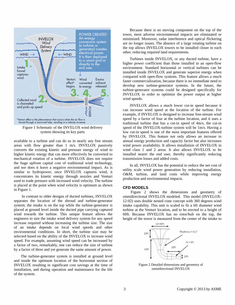
INVELOX SYSTEM The five key parts of INVELOX are shown in Figure 1.
These key parts are (1) intake, (2) pipe carrying and accelerating wind, (3) boosting wind speed by a Venturi, (4) wind energy conversions system, and (5) a diffuser. The fundamental of the INVELOX system is that it separates the turbine from the intake, very much like traditional hydropower plants that use large dams to build pressure and use wind density and gravity to reach turbines at high kinetic energy levels. The size of the dam is much bigger than the size of the hydro turbine. INVELOX is based on hydropower principals. The difference is INVELOX captures the wind kinetic energy and uses the pressure differentials to increase the kinetic energy
3 Copyright © 2013 by ASME
available to a turbine and can do so in nearly any free stream areas with flow greater than 1 m/s. INVELOX passively converts the existing kinetic and pressure energy of wind to higher kinetic energy that can more effectively be converted to mechanical rotation of a turbine. INVELOX does not require the huge upfront capital cost of traditional wind technology, and nor does it leave a negative environmental impact. As is similar to hydropower, once INVELOX captures wind, it concentrates its kinetic energy through nozzles and Venturi used to trade pressure with increased wind velocity. The turbine is placed at the point when wind velocity is optimum as shown in Figure 1.
In contrast to older designs of ducted turbines, INVELOX separates the location of the shroud and turbine-generator system; the intake is on the top while the turbine-generator is placed at ground level inside the ducted pipe carrying captured wind towards the turbine. This unique feature allows the engineers to size the intake wind delivery system for any speed increase required without increasing the turbine size. The size of an intake depends on local wind speeds and other environmental conditions. In short, the turbine size may be selected based on the ability of the INVELOX to increase wind speed. For example, assuming wind speed can be increased by a factor of two, remarkably, one can reduce the size of turbine by a factor of three and yet generate the same amount of power.
The turbine-generator system is installed at ground level and inside the optimum location of the horizontal section of INVELOX resulting in significant cost savings at the time of installation, and during operation and maintenance for the life of the system.
Because there is no moving component on the top of the tower, most adverse environmental impacts are eliminated or minimized. Moreover, radar interference and optical flickering are no longer issues. The absence of a large rotating turbine on the top allows INVELOX towers to be installed closer to each other, reducing required land requirements.
Turbines inside INVELOX, or any ducted turbine, have a higher power coefficient than those installed in an open-flow environment. Standard horizontal or vertical turbines can be installed inside INVELOX and generate superior energy when compared with open-flow systems. This feature allows a much faster commercialization, because there is no immediate need to develop new turbine-generator systems. In the future, the turbine-generator systems could be designed specifically for INVELOX in order to optimize the power output at higher wind speeds.
INVELOX allows a much lower cut-in speed because it can increase wind speed at the location of the turbine. For example, if INVELOX is designed to increase free-stream wind speed by a factor of four at the turbine location, and it uses a traditional turbine that has a cut-in speed of 4m/s, the cut-in speed of the INVELOX-turbine system will be 1m/s. Having a low cut-in speed is one of the most important features offered by INVELOX. This feature not only allows an increase in annual energy production and capacity factor but also increases wind power availability. It allows installation of INVELOX in wind class 1 and 2 areas. It also allows INVELOX to be installed nearer the end user, thereby significantly reducing transmission losses and added costs.
In all, INVELOX has the potential to reduce the net cost of utility scale wind power generation by reducing installation, O&M, turbine, and land costs while improving energy production and environmental impacts.
CFD MODELS Figure 2 shows the dimensions and geometry of
omnidirectional INVELOX modeled. This model (INVELOX-12-02) uses double nested cone concept with 360 degrees wind intake capability. This unit is scaled to fit a 6ft diameter wind turbine at the Venturi location, and to be erected to a height of 60ft. Because INVELOX has no rotor/hub on the top, the height of the tower is measured from the center of the intake to
Figure 2 Detailed dimensions and geometry of
omnidirectional INVELOX
Figure 1 Schematic of the INVELOX wind delivery system showing its key parts
5 Copyright © 2013 by ASME
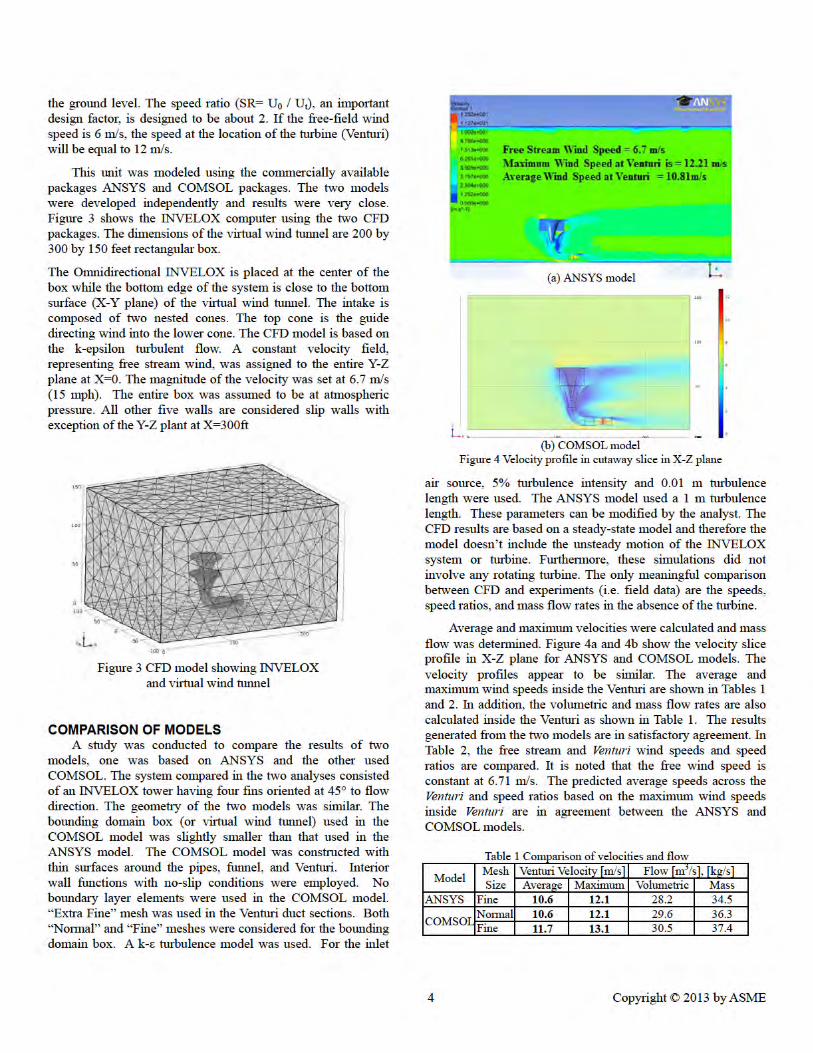
Table 2 Comparison of velocities and speed ratios (SR)
Model Mesh Size
Free Stream [m/s]
Venturi Velocity [m/s]
Speed Ratio (SR)
Average Max Average MaxANSYS Fine 6.71 10.6 12.1 1.58 1.80
COMSOL Normal 6.71 10.6 12.1 1.58 1.80Fine 6.71 11.7 13.1 1.74 1.95
FIELDED DEMOS AND MEASURED DATA INVELOX with No Turbine – In order to compare the
field data with those generated by the CFD models, we collected wind speed data when the turbine was not placed inside the Venturi section of INVELOX.
Figure 5A shows the measured free stream and Venturi wind speeds for 24 data sets with Sunforce turbine inside the Venturi section of INVELOX. The instantaneous speed ratio (SR) and average SR are also displayed. It is noted that SR varies from 1.5 to 2.1 with an average value of about 1.8. The SR values are in satisfactory agreement with those predicted by the CFD models and reported in Table 2.
Figure 5B shows the scaled version of the data presented in Figure 5A. In order to compare the result with those predicted by the CFD models, the data was scaled based on a constant free stream wind speed of 6.71 m/s. It is noted that the Venturi wind speed follows the same trend as the instantaneous SR shown in Figure 5A. The average mass flow was determined to be about 34.30 Kg/s; this value is in satisfactory agreement with those predicted by the CFD models in Table 2.
Figure 5A Raw field data and speed ratios for 24 data sets
Figure 5B Scaled field data based on constant free stream wind speed at 6.71 m/s and mass flow rate for 24 data sets
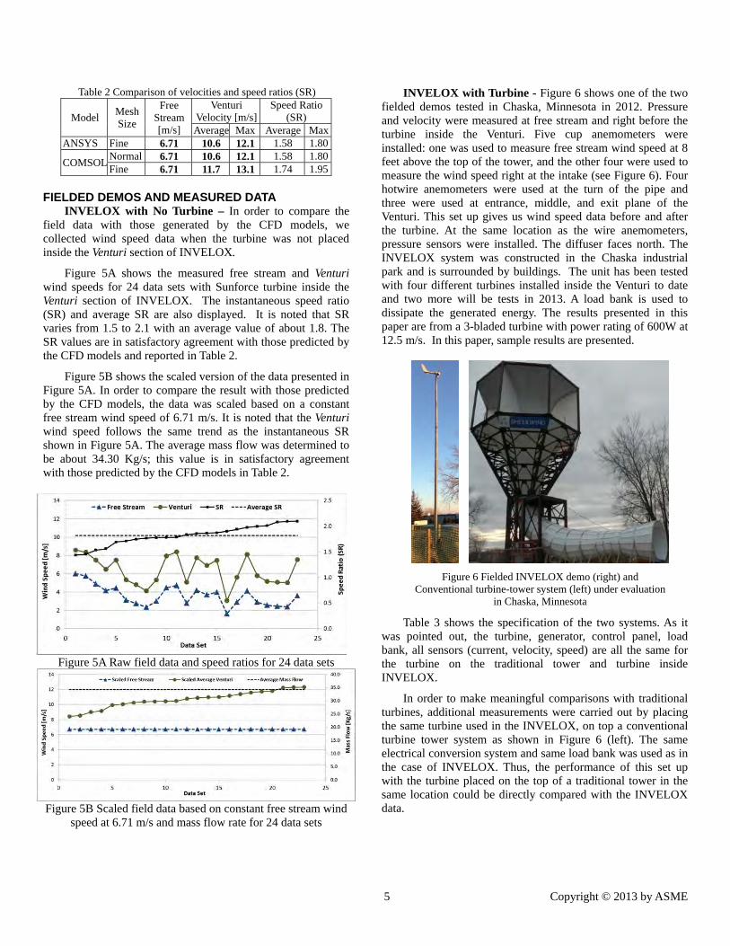
INVELOX with Turbine - Figure 6 shows one of the two fielded demos tested in Chaska, Minnesota in 2012. Pressure and velocity were measured at free stream and right before the turbine inside the Venturi. Five cup anemometers were installed: one was used to measure free stream wind speed at 8 feet above the top of the tower, and the other four were used to measure the wind speed right at the intake (see Figure 6). Four hotwire anemometers were used at the turn of the pipe and three were used at entrance, middle, and exit plane of the Venturi. This set up gives us wind speed data before and after the turbine. At the same location as the wire anemometers, pressure sensors were installed. The diffuser faces north. The INVELOX system was constructed in the Chaska industrial park and is surrounded by buildings. The unit has been tested with four different turbines installed inside the Venturi to date and two more will be tests in 2013. A load bank is used to dissipate the generated energy. The results presented in this paper are from a 3-bladed turbine with power rating of 600W at 12.5 m/s. In this paper, sample results are presented.
Table 3 shows the specification of the two systems. As it was pointed out, the turbine, generator, control panel, load bank, all sensors (current, velocity, speed) are all the same for the turbine on the traditional tower and turbine inside INVELOX.
In order to make meaningful comparisons with traditional turbines, additional measurements were carried out by placing the same turbine used in the INVELOX, on top a conventional turbine tower system as shown in Figure 6 (left). The same electrical conversion system and same load bank was used as in the case of INVELOX. Thus, the performance of this set up with the turbine placed on the top of a traditional tower in the same location could be directly compared with the INVELOX data.
Figure 6 Fielded INVELOX demo (right) and Conventional turbine-tower system (left) under evaluation
in Chaska, Minnesota

6 Copyright © 2013 by ASME
Table 3 System specifications
Item Traditional
Tower INVELOX
Model (SF = Sunforce) SF 600 SF 600 Rotor diameter [m] 1.31 1.31 Rated free stream wind speed [m/s] 12.5 6.25 Rated power [W] 600 600 Voltage [V] 24 24 Rated load Current [A], maximum 35 35 Generator 3-phase 3-phase
Free stream wind speed [m/s] Cut-in 2.0 1.0 Survival 70.0 35.0
Number of Blades 3 3 Blade material Fiber glass Fiber glass Resistive load bank [ohms] 10 10 Tower height [m] 10 18.3 Over-speed braking [rpm] 1400 1400
Figure 7 shows that higher wind speeds were maintained even when a turbine was placed inside the Venturi section of INVELOX. In addition, recorded data shows that the intake is indeed omnidirectional; the system performs well in all wind directions. Furthermore, Chaska, Minnesota is generally considered a class 1 or 2 wind area which is verified by free stream wind speeds recorded as shown in the figure. However, wind speeds recorded inside the Venturi section of INVELOX show that winds are converted to class 3.
Figure 8 shows the daily energy production improvements of INVELOX with respect to the traditional WTG system. The results show INVELOX generated 80% to 640% more
electrical energy than the traditional WTGs. The total energy production of INVELOX over 8 days is about 314%.
CONCLUSIONS
It was shown that INVELOX can be designed to capture and accelerate wind using an omnidirectional intake. Increased wind speed was maintained when turbine was installed inside the Venturi section. The system has low sensitivity with respect to wind direction. Due to increased wind speeds, INVELOX-turbine system generated significantly more energy than the tower-turbine systems with the same turbine size. INVELOX has a strong potential and is worthy of further development.
ACKNOWLEDGMENTS
This work was supported by SheerWind and CCNY. Their generous support is greatly appreciated.
REFERENCES 1. A. Grant and N. Kelly, “The Development of a Ducted Wind Turbine Simulation Model,” Eighth International IBPSA Conference, Eindhoven, Netherlands, 2003. 2. “First installation of a WindTamer Wind Turbine in Europe”, available at http://aristapower.com/2011/08/first-installation-of-a-windtamer-wind-turbine-in-europe/, 2011. 3. I.H. Al-Bahadly and A.F.T. Petersen, “A Ducted Horizontal Wind Turbine for Efficient Generation”, ISBN: 978-953-307-221-0, available at www.intechopen.com, 2011. 4. D. Allaei, J. E. Gonzalez, A. M. Sadegh, Y. Andreopoulos, D. Tarnowski, “INVELOX-Affordable Wind Power for Anyone Anywhere”, WindTech International, March 2013. 5. D. Allaei, “Game Changing Wind Power Technologies”, Invited Speaker, Clean Tech Connect, Phoenix, AZ, March 2013. 6. D. Allaei. “Using CFD to Predict the Performance of Innovative Wind Power Generators”, Proceedings of the 2012 COMCOL Conference in Boston, 2012. 7. D. Allaei, “Review of Alternative Wind Power Generation Technologies”, Second New Energy and Wind Energy Forum, Guangzhou, China, October 2012. 8. D. Allaei, “Wind Power Generation Technologies,” 2012 Energy Issues Summit, MN, August 2012. 9. D. Allaei, “Affordable Clean Power Solutions for Buildings Anywhere,” USGBC Minnesota’s First Annual IMPACT Conference, Minneapolis, MN, September 2012. 10. D. Allaei, “Turbine-Intake Tower for Wind Energy Conversion Systems,” 2010 US Patent No 7,811,048. 11. D. Allaei, “Power Generating Skin Structure and Power Generation System Thereof,” 2010 US Patent No 7,812,472. 12. Lawn CJ “Optimization of the power output from ducted turbines”, Proc. Instn Mech. Engrs Vol. 217, J. Power and Energy. 13. Politis, GK., and Koras, AD. “A performance prediction method for ducted medium loaded horizontal axis wind turbines”, Wind Engng, 19(5), 273–288, 1995. 14. Georgalas, CG, Koras, AD, and Raptis, SN, “Parameterization of the power enhancement calculated for ducted rotors with large tip clearance”, Wind Engng, 15(3), 128–136, 1991. 15. Frankovic, B. and Vrsalovic, I. “New high portable wind turbines”, Renewable Energy, 24, 491–499, 2001.
Figure 7 Free-stream and turbine wind speed and wind direction data measured over 8 days
Figure 8 Daily energy production improvements - the INVELOX with respect to traditional turbine-tower systems