Embed Size (px)
Citation preview

1
Introduction
Experience is a valuable asset to have in virtually all aspects of design and construction. With experience comesthe understanding of how concepts can become reality. But at what point do our preconceived beliefs on howthings work begin to limit change and progress?Albert Einstein summarized this concept in a simplequote, "Imagination is Much More Important thanKnowledge; Knowledge is Limited, ImaginationEncircles the World". Allan Block Corporation iscontinuing our quest to develop more efficient anddynamic building materials from the most versatile,environmentally friendly and affordable buildingmaterial known to mankind - concrete. In this sum-mary report we document how the AB Fence sys-tem performs when subjected to lateral loads, dif-ferential base support and expansive soil loading.
Product Profile
The AB Fence system combines the benefits of mortarless technology with the time proven performance of rein-forced concrete. The patented ball and socket seating elements have revolutionized the process of construct-ing masonry structures. The three main structural components are the AB Fence Post, the AB Fence Panel Blockand the AB Fence Capstone. Together they provide the ability to design and create a fence that meets the con-figuration requirements of each individual project.
The AB Post Blocks aredry-stacked on top ofreinforced pilings andfully grouted with rein-forcing steel. They arethe primary structuralelement in the system.
The AB Fence Cornerscreate 90º transitionswithout miter cuttingAB Post Blocks.
The AB Panel Blockfeatures a “ball andsocket” connectionthat allows the dry-stacked blocks to forma fully interlocked wallpanel without the useof mortar.
The AB Cap Block isused to finish the tops ofthe post and panels.
AB Post Block AB Panel Block
AB Cap Block Fence Corner Unit
Fence Testing Executive Summary
Page PageIntroduction 1-2 Test Procedures 7Test Objectives 3 Test Summary 8Facilities and Test Apparatus 4 Testing Photos 9-10Test Setup 5-6

2
The goal of this testing was to confirm the structural performance character-istics of the AB Fence System relative to a typical masonry design approach.Through testing we illustrate how concrete masonry structures, that vary fromtypical mortared structures, are able to provide benefits outside of the scopeof typical masonry construction. We demonstrate how the mortarless, dry-stacked AB Fence system performs under loads commonly applied to fenc-ing and sound barrier structures. The self weight of the AB Fence blocks mobi-lizes the ball and socket elements of the block. With the addition of selfweight, the ball and socket increases the rigidity of the panel while maintain-ing a flexible system. This combination of flexibility and increased rigidity cre-ates a system that absorbs a portion of the applied loads.
The post and panel configuration concept develops a structural columnapproach to transferring load from the panels to the columns. The columnsare anchored to the ground with variable depth and diameter pilesdepending on the spacing between the columns, the height of the structure,the soil conditions and the loading conditions. This concept begins withbasic principles used to construct masonry fences.
The results presented in this report substantiate the unparalleled perform-ance of a concrete masonry post and panel system that is flexible and ableto absorb load rather than simply transfer load. This provides the basis to usetypical masonry design methods for a system that performs better than blockand mortar construction. This testing also validates product specific baseddesign methods which utilize the efficiencies of the AB Fence System.
Research Team:Dr. Nigel Shrive, Department of Civil Engineering, University of CalgaryRyan Bakay, Department of Civil Engineering, University of CalgaryBlair Scholelfield, Department of Civil Engineering, University of Calgary
Full Scale Panel and Post Testing
3
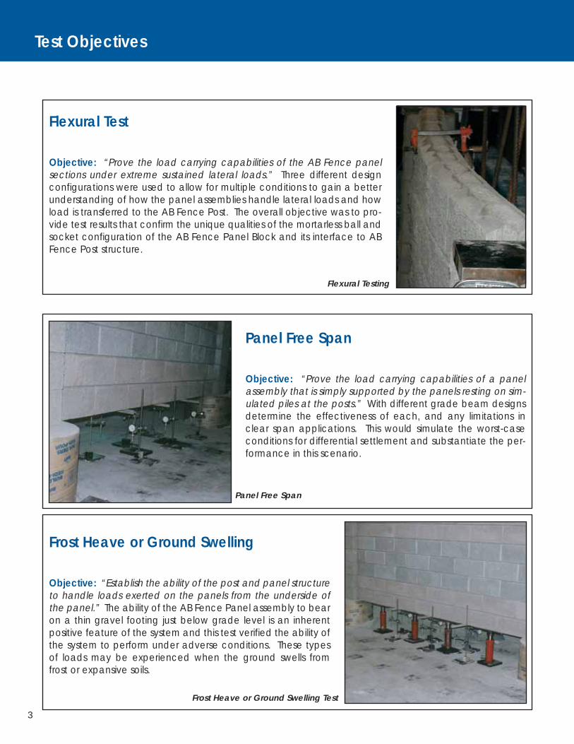
Flexural Test
Objective: “Prove the load carrying capabilities of the AB Fence panelsections under extreme sustained lateral loads.” Three different designconfigurations were used to allow for multiple conditions to gain a betterunderstanding of how the panel assemblies handle lateral loads and howload is transferred to the AB Fence Post. The overall objective was to pro-vide test results that confirm the unique qualities of the mortarless ball andsocket configuration of the AB Fence Panel Block and its interface to ABFence Post structure.
Panel Free Span
Objective: “Prove the load carrying capabilities of a panelassembly that is simply supported by the panels resting on sim-ulated piles at the posts.” With different grade beam designsdetermine the effectiveness of each, and any limitations inclear span applications. This would simulate the worst-caseconditions for differential settlement and substantiate the per-formance in this scenario.
Frost Heave or Ground Swelling
Objective: “Establish the ability of the post and panel structureto handle loads exerted on the panels from the underside ofthe panel.” The ability of the AB Fence Panel assembly to bearon a thin gravel footing just below grade level is an inherentpositive feature of the system and this test verified the ability ofthe system to perform under adverse conditions. These typesof loads may be experienced when the ground swells fromfrost or expansive soils.
Flexural Testing
Frost Heave or Ground Swelling Test
Panel Free Span
Test Objectives
4
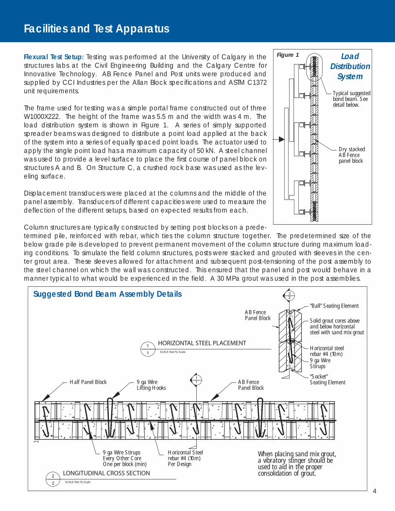
Flexural Test Setup: Testing was performed at the University of Calgary in thestructures labs at the Civil Engineering Building and the Calgary Centre forInnovative Technology. AB Fence Panel and Post units were produced andsupplied by CCI Industries per the Allan Block specifications and ASTM C1372unit requirements.
The frame used for testing was a simple portal frame constructed out of threeW1000X222. The height of the frame was 5.5 m and the width was 4 m. Theload distribution system is shown in Figure 1. A series of simply supportedspreader beams was designed to distribute a point load applied at the backof the system into a series of equally spaced point loads. The actuator used toapply the single point load has a maximum capacity of 50 kN. A steel channelwas used to provide a level surface to place the first course of panel block onstructures A and B. On Structure C, a crushed rock base was used as the lev-eling surface.
Displacement transducers were placed at the columns and the middle of thepanel assembly. Transducers of different capacities were used to measure thedeflection of the different setups, based on expected results from each.
Column structures are typically constructed by setting post blocks on a prede-termined pile, reinforced with rebar, which ties the column structure together. The predetermined size of thebelow grade pile is developed to prevent permanent movement of the column structure during maximum load-ing conditions. To simulate the field column structures, posts were stacked and grouted with sleeves in the cen-ter grout area. These sleeves allowed for attachment and subsequent post-tensioning of the post assembly tothe steel channel on which the wall was constructed. This ensured that the panel and post would behave in amanner typical to what would be experienced in the field. A 30 MPa grout was used in the post assemblies.
LoadDistribution
System
Figure 1
SCALE: Not To Scale
LONGITUDINAL CROSS SECTION 2
2
HORIZONTAL STEEL PLACEMENT SCALE: Not To Scale1
1
11
22
Half Panel Block 9 ga WireLifting Hooks
AB FencePanel Block
9 ga Wire StirupsEvery Other CoreOne per block (min)
9 ga WireStirups
Horizontal Steelrebar #4 (10m)Per Design
AB FencePanel Block Solid grout cores above
and below horizontalsteel with sand mix grout
Typical suggestedbond beam. Seedetail below.
Dry stackedAB Fencepanel block
Horizontal steelrebar #4 (10m)
“Socket”Seating Element
“Ball” Seating Element
Suggested Bond Beam Assembly Details
When placing sand mix grout,a vibratory stinger should beused to aid in the properconsolidation of grout.
Facilities and Test Apparatus
5
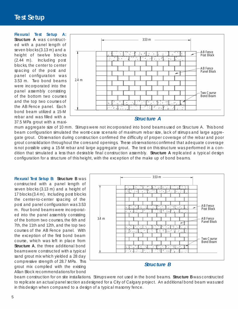
Flexural Test Setup A:Structure A was construct-ed with a panel length ofseven blocks (3.13 m) and aheight of twelve blocks(2.44 m). Including postblocks, the center to centerspacing of the post andpanel configuration was3.53 m. Two bond beamswere incorporated into thepanel assembly consistingof the bottom two coursesand the top two courses ofthe AB Fence panel. Eachbond beam utilized a 15-Mrebar and was filled with a37.5 MPa grout with a maxi-mum aggregate size of 10 mm. Stirrups were not incorporated into bond beams used on Structure A. This bondbeam configuration simulated the worst-case scenario of maximum rebar size, lack of stirrups and large aggre-gate grout. Observation during construction confirmed the difficulty of proper coverage of the rebar and poorgrout consolidation throughout the cores and openings. These observations confirmed that adequate coverageis not possible using a 15-M rebar and large aggregate grout. The test on this structure was performed in a con-dition that simulated a less than desirable final construction assembly. Structure A replicated a typical designconfiguration for a structure of this height, with the exception of the make up of bond beams.
Flexural Test Setup B: Structure B wasconstructed with a panel length ofseven blocks (3.13 m) and a height of17 blocks (3.4 m). Including post blocksthe center-to-center spacing of thepost and panel configuration was 3.53m. Four bond beams were incorporat-ed into the panel assembly consistingof the bottom two courses, the 6th and7th, the 11th and 12th, and the top twocourses of the AB Fence panel. Withthe exception of the first bond beamcourse, which was left in place fromStructure A, the three additional bondbeams were constructed with a typicalsand grout mix which yielded a 28 daycompressive strength of 28.7 MPa. Thisgrout mix complied with the existingAllan Block recommendations for bondbeam construction for on site installations. Stirrups were not used in the bond beams. Structure B was constructedto replicate an actual panel section as designed for a City of Calgary project. An additional bond beam was usedin this design when compared to a design of a typical masonry fence.
Structure A
Structure B
Test Setup
AB FencePost Block
AB FencePanel Block
Two CourseBond Beam
AB FencePost Block
3.53 m
2.4 m
3.53 m
3.4 m
AB FencePanel Block
Two CourseBond Beam
6
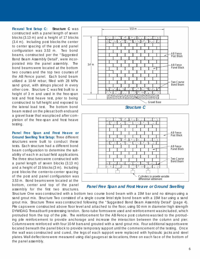
Flexural Test Setup C: Structure C wasconstructed with a panel length of sevenblocks (3.13 m) and a height of 17 blocks(3.4 m). Including post blocks the centerto center spacing of the post and panelconfiguration was 3.53 m. Two bondbeams, constructed per the “SuggestedBond Beam Assembly Detail”, were incor-porated into the panel assembly. Thebond beams were located at the bottomtwo courses and the top two courses ofthe AB Fence panel. Each bond beamutilized a 10-M rebar, filled with 28 MPasand grout, with stirrups placed in everyother core. Structure C was first built to aheight of 3 m and used in the free-spantest and frost heave test, prior to beingconstructed to full height and exposed tothe lateral load test. The bottom bondbeam rested on the piles at both ends anda gravel base that was placed after com-pletion of the free-span and frost heavetesting.
Panel Free Span and Frost Heave orGround Swelling Test Setup: Three differentstructures were built to conduct thesetests. Each structure had a different bondbeam configuration to determine the suit-ability of each in actual field applications.The three structures were constructed witha panel length of seven blocks (3.13 m)and a height of 15 blocks (3 m). Includingpost blocks the center-to-center spacingof the post and panel configuration was3.53 m. Bond beams were located at thebottom, center and top of the panelassembly for the first two structures.Structure One was constructed with a bottom two course bond beam with a 15M bar and no stirrups using asand grout mix. Structure Two consisted of a single course lintel style bond beam with a 15M bar using a sandgrout mix. Structure Three was constructed following the “Suggested Bond Beam Assembly Detail” (page 4).Pile caps were constructed above floor level and attached to the floor, using 50 mm in diameter high strengthDYWIDAG Threadbar® prestressing tendon. Sono-tube forms were used and reinforcement was included, whichprotruded from the top of the pile. The reinforcement for the AB Fence post columns was tied to the protrud-ing pile reinforcement to provide anchorage and increase the interaction between the column and pier.Columns were reinforced with four 10-M bars and grouted with a sand grout mix. Four additional supports werelocated beneath the panel block to provide temporary support until the commencement of the testing. Oncethe wall was constructed and cured, the legs of each support were replaced with hydraulic jacks and steelplates. Wall deflections were measured using dial gauges at six locations, three on each face of the bottom ofthe panel assembly.
Structure C
Panel Free Span and Frost Heave or Ground Swelling
AB FencePost Block
AB FencePanel Block
Two CourseBond Beam
AB FencePost Block
AB FencePanel Block
Two CourseBond Beam
Gravel Base
3.53 m
3.4 m
Cylinders to provide variabledifferential settlement

7
Flexural Test: To simulate a sustained wind load, a load spreading system was positioned on one side of the ABFence panels. On the other side of the panel, deflection gauges were placed at one-meter vertical intervals andone-meter horizontal intervals. A horizontal applied load from a hydraulic ram was applied to the fence with theload spreading system. Deflection readings were taken as the forces were applied. Strain gauges were attachedto the rebar in the bond beam to measure how much load was being transmitted to the bond beam reinforce-ment. This also provided information to derive how much load was absorbed by the ball and socket connection,which is integral to the panel block assemblies.
Incremental forces were applied and recorded to provide documentation of unfactored wind loads at 97 km/hthrough 386 km/h in increments of 16 km/h. The total time elapsed for the sustained load was recorded as wellas the time at each increment prior to increasing the load. Deflection readings at the panel and the posts wererecorded at each incremental load.
At completion of the test, the load was removed and the permanent deflection was recorded.
Panel Free Span: To simulate a complete free span condition of the panel assemblies, that are simply supportedby piles on both ends, the temporary supports were removed. Deflection was recorded after the removal of allsupports.
Frost Heave or Ground Swelling: Upon completion of the Panel Free Span test, floor supports were repositioned toestablish a level ground condition. To simulate the effects of localized frost heave, loads were applied at three loca-tions, the ¼ panel mark, ½ panel mark and ¾ panel mark. Loading was accomplished by using a jack that was push-ing on a steel plate measuring 150 mm by 450 mm located below the bond beam. Starting with the right side, thejack was engaged to apply a load of 30 kN, while the other panel marks were simply supported simulating stable sub-grade. A deflection reading was recorded to document the movement associated with a 30 kN ground movementload. The panel was lowered to its starting position. The test was conducted again in the mid point of the bondbeam and on the opposite side at the ¾ panel length mark. This procedure provides performance information fordifferential ground heave conditions within one panel assembly.
Test Procedures
In order for bulging to occur in the panel, the locking forces within the ball and socket joint of the dry-stacked unitsmust literally lift the courses of block above the bulge. The self weight of these courses enhances the strength andrigidity of the panel and continues to increase as you move lower in the panel.
Applied Wind Load Dry-stack unitsinterlock utilizing the ball and socketconfiguration.
8
Testing Summary
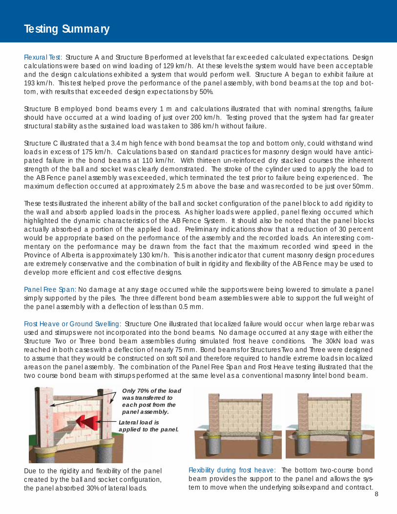
Due to the rigidity and flexibility of the panelcreated by the ball and socket configuration,the panel absorbed 30% of lateral loads.
Flexibility during frost heave: The bottom two-course bondbeam provides the support to the panel and allows the sys-tem to move when the underlying soils expand and contract.
Lateral load isapplied to the panel.
Only 70% of the loadwas transferred to each post from thepanel assembly.
Flexural Test: Structure A and Structure B performed at levels that far exceeded calculated expectations. Designcalculations were based on wind loading of 129 km/h. At these levels the system would have been acceptableand the design calculations exhibited a system that would perform well. Structure A began to exhibit failure at193 km/h. This test helped prove the performance of the panel assembly, with bond beams at the top and bot-tom, with results that exceeded design expectations by 50%.
Structure B employed bond beams every 1 m and calculations illustrated that with nominal strengths, failureshould have occurred at a wind loading of just over 200 km/h. Testing proved that the system had far greaterstructural stability as the sustained load was taken to 386 km/h without failure.
Structure C illustrated that a 3.4 m high fence with bond beams at the top and bottom only, could withstand windloads in excess of 175 km/h. Calculations based on standard practices for masonry design would have antici-pated failure in the bond beams at 110 km/hr. With thirteen un-reinforced dry stacked courses the inherentstrength of the ball and socket was clearly demonstrated. The stroke of the cylinder used to apply the load tothe AB Fence panel assembly was exceeded, which terminated the test prior to failure being experienced. Themaximum deflection occurred at approximately 2.5 m above the base and was recorded to be just over 50mm.
These tests illustrated the inherent ability of the ball and socket configuration of the panel block to add rigidity tothe wall and absorb applied loads in the process. As higher loads were applied, panel flexing occurred whichhighlighted the dynamic characteristics of the AB Fence System. It should also be noted that the panel blocksactually absorbed a portion of the applied load. Preliminary indications show that a reduction of 30 percentwould be appropriate based on the performance of the assembly and the recorded loads. An interesting com-mentary on the performance may be drawn from the fact that the maximum recorded wind speed in theProvince of Alberta is approximately 130 km/h. This is another indicator that current masonry design proceduresare extremely conservative and the combination of built in rigidity and flexibility of the AB Fence may be used todevelop more efficient and cost effective designs.
Panel Free Span: No damage at any stage occurred while the supports were being lowered to simulate a panelsimply supported by the piles. The three different bond beam assemblies were able to support the full weight ofthe panel assembly with a deflection of less than 0.5 mm.
Frost Heave or Ground Swelling: Structure One illustrated that localized failure would occur when large rebar wasused and stirrups were not incorporated into the bond beams. No damage occurred at any stage with either theStructure Two or Three bond beam assemblies during simulated frost heave conditions. The 30kN load wasreached in both cases with a deflection of nearly 75 mm. Bond beams for Structures Two and Three were designedto assume that they would be constructed on soft soil and therefore required to handle extreme loads in localizedareas on the panel assembly. The combination of the Panel Free Span and Frost Heave testing illustrated that thetwo course bond beam with stirrups performed at the same level as a conventional masonry lintel bond beam.

9
Assembled 17 Course Block WallStructure B
Displacement TransducersMeasuring Rotation
Top Bond Beam Structure A
Post-Tensioned Masonry Posts Top Bond Beam Structure A Deflection
Flexural Test Setup Structure C Flexural Test Setup Structure C(2 bond beams and 13 dry-stacked courses)
Testing Photos and Test Setup
Flexural Testing PhotosThe overall objective was to provide test results that confirmed the unique qualities of the mortarless ball and socket configuration of theAB Fence Panel Block and its interface to the AB Fence Post structure.

10
Panel Movement Under Frost Heave Loading
Hydraulic Jacks Dial Gauges for MeasuringDeflection
Panel Free Span and Frost Heave or Ground Swelling Testing Photos
A two part objective. The first to provethe load carrying capabilities of a panelassembly that is simply supported by thepanels resting on simulated piles at theposts. Second, to establish the ability ofthe post and panel structure to handleloads exerted on the panels from theunderside.
Bond beam first course.
#4 (10m) rebar at firstcourse (maximum size).
Lifting hook ifprecasting.
Small diameter stingervibrator to assist the flowof grout around rebar.
Sandgrout mix. Vertical hooked stirrups in
every other core. For ease ofinstallation place prior tostinging. Reposition as need-ed during final stages ofgrouting and stinging.
Bond beamsecond course.
Stirrup
Proper Bond Beam Construction
Assembled Block Wall

Allan Block Corporation is continuing our quest to develop more efficient and
dynamic building materials from the most versatile, environmentally friendly and
affordable material known to man kind, concrete. In this summary report we
document how the AB Fence system performs when subjected to lateral loads,
differential base support and expansive soil loading.
For more information on AB Fence visit our web site or call the
Allan Block Engineering Department at 800-899-5309.
© 2005 Allan Block Corporation 5300 Edina Industrial Blvd, Edina, MN 55439 952-835-5309 - Phone 952-835-0013 - Fax US Patent # 5,623,797 & 6,082,067 Canadian Patent #2,182,321 Int'l and other patents pending F0205-0607
The information shown here is for use with Allan Block products only.