Embed Size (px)
Citation preview
Alleviating Garbage Collection Interference through Spatial Separation in All Flash Arrays
Jaeho Kim, Kwanghyun Lim*, Youngdon Jung, Sungjin Lee, Changwoo Min, Sam H. Noh
*Currently with Cornell Univ. 30
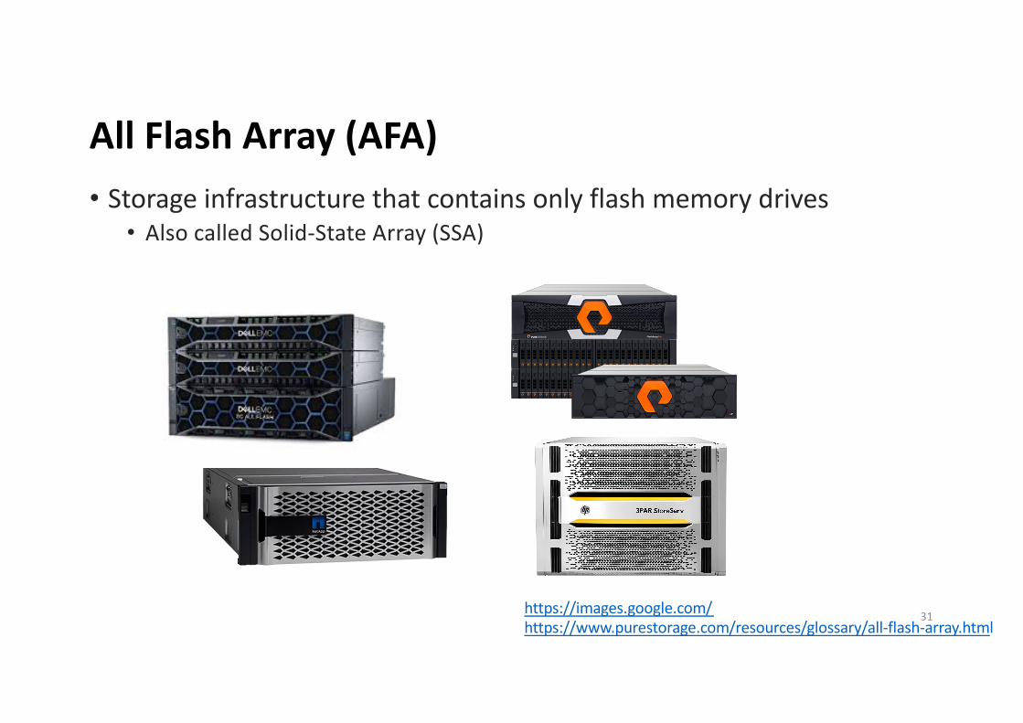
All Flash Array (AFA) • Storage infrastructure that contains only flash memory drives
• Also called Solid-State Array (SSA)
https://images.google.com/https://www.purestorage.com/resources/glossary/all-flash-array.html
31
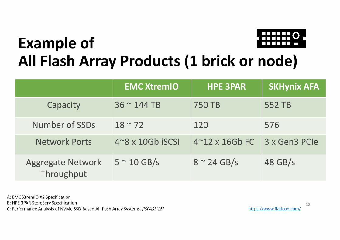
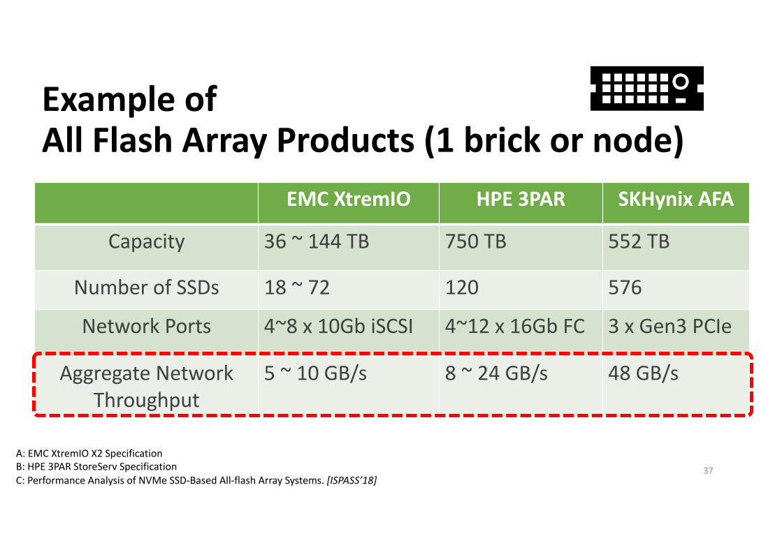
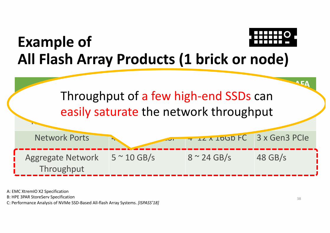
Example of All Flash Array Products (1 brick or node)
EMC XtremIO HPE 3PAR SKHynix AFA
Capacity 36 ~ 144 TB 750 TB 552 TB
Number of SSDs 18 ~ 72 120 576
Network Ports 4~8 x 10Gb iSCSI 4~12 x 16Gb FC 3 x Gen3 PCIe
Aggregate Network Throughput
5 ~ 10 GB/s 8 ~ 24 GB/s 48 GB/s
A: EMC XtremIO X2 SpecificationB: HPE 3PAR StoreServ SpecificationC: Performance Analysis of NVMe SSD-Based All-flash Array Systems. [ISPASS’18]
32https://www.flaticon.com/
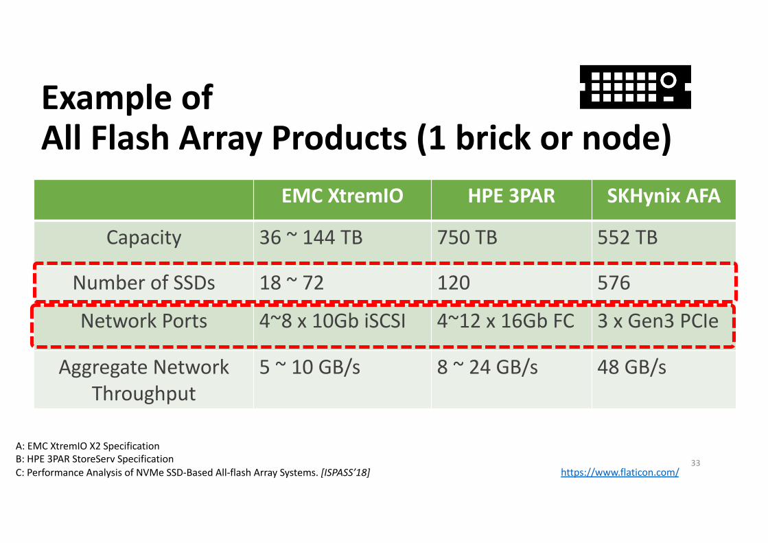
Example of All Flash Array Products (1 brick or node)
EMC XtremIO HPE 3PAR SKHynix AFA
Capacity 36 ~ 144 TB 750 TB 552 TB
Number of SSDs 18 ~ 72 120 576
Network Ports 4~8 x 10Gb iSCSI 4~12 x 16Gb FC 3 x Gen3 PCIe
Aggregate Network Throughput
5 ~ 10 GB/s 8 ~ 24 GB/s 48 GB/s
A: EMC XtremIO X2 SpecificationB: HPE 3PAR StoreServ SpecificationC: Performance Analysis of NVMe SSD-Based All-flash Array Systems. [ISPASS’18]
33https://www.flaticon.com/
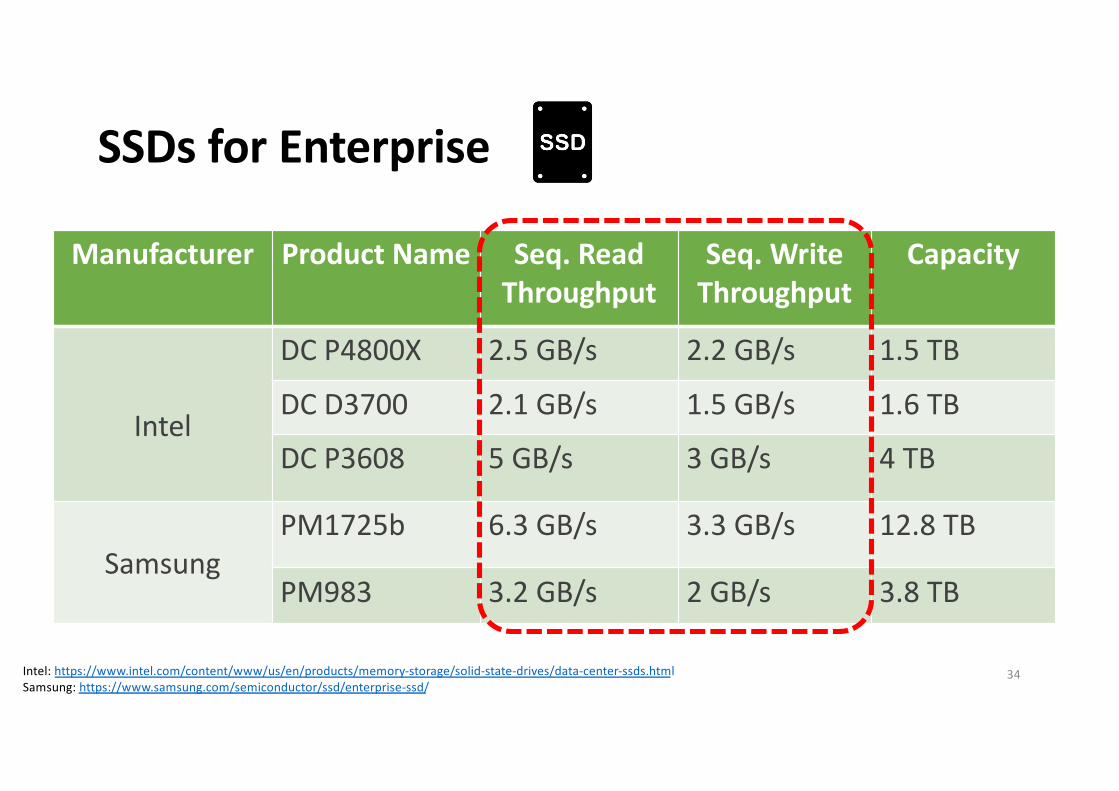
SSDs for Enterprise
Manufacturer Product Name Seq. Read Throughput
Seq. WriteThroughput
Capacity
Intel
DC P4800X 2.5 GB/s 2.2 GB/s 1.5 TB
DC D3700 2.1 GB/s 1.5 GB/s 1.6 TB
DC P3608 5 GB/s 3 GB/s 4 TB
SamsungPM1725b 6.3 GB/s 3.3 GB/s 12.8 TB
PM983 3.2 GB/s 2 GB/s 3.8 TB
Intel: https://www.intel.com/content/www/us/en/products/memory-storage/solid-state-drives/data-center-ssds.htmlSamsung: https://www.samsung.com/semiconductor/ssd/enterprise-ssd/
34
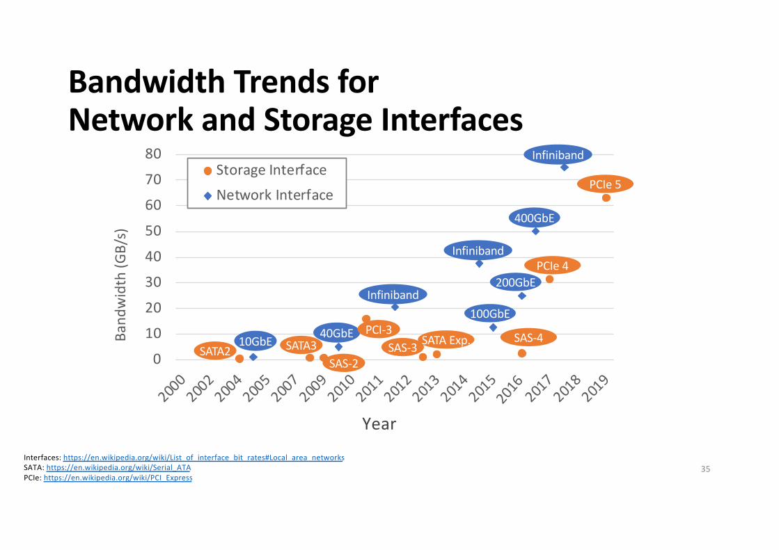
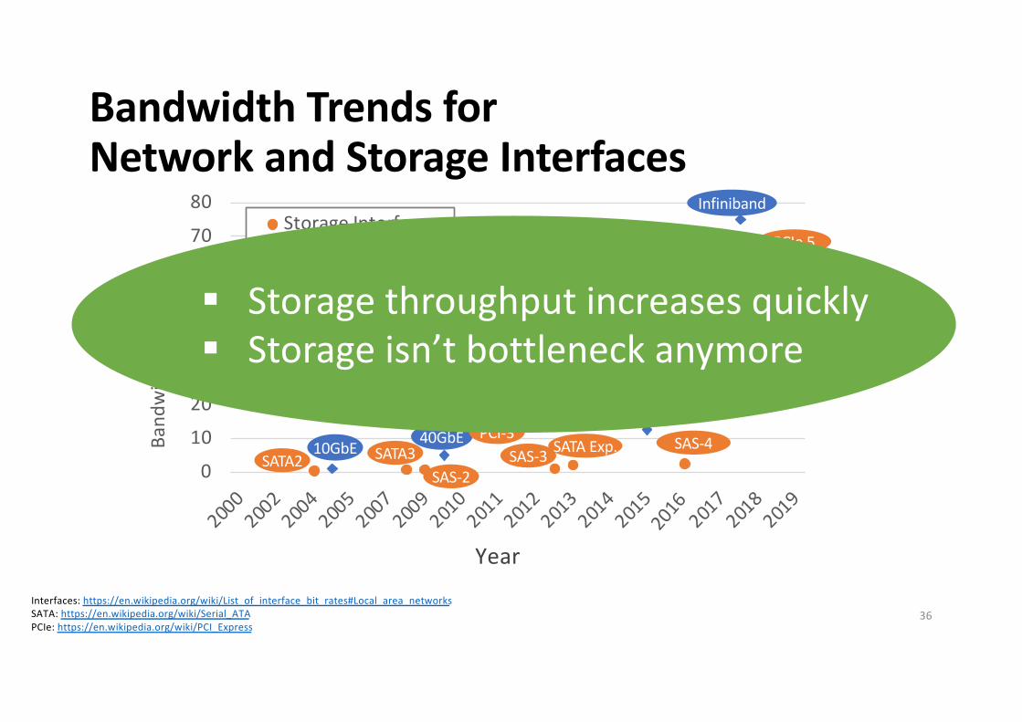
Bandwidth Trends for Network and Storage Interfaces
Interfaces: https://en.wikipedia.org/wiki/List_of_interface_bit_rates#Local_area_networksSATA: https://en.wikipedia.org/wiki/Serial_ATAPCIe: https://en.wikipedia.org/wiki/PCI_Express
01020304050607080
2000
2002
2004
2005
2007
2009
2010
2011
2012
2013
2014
2015
2017
2017
2018
2019
Band
wid
th (G
B/s)
Storage InterfaceNetwork Interface
Year
10GbE 40GbE
Infiniband
Infiniband
100GbE
200GbE
400GbE
Infiniband
SATA2 SATA3SAS-2
PCI-3SAS-3 SATA Exp. SAS-4
PCIe 4
PCIe 5
35
2016
Bandwidth Trends for Network and Storage Interfaces
Interfaces: https://en.wikipedia.org/wiki/List_of_interface_bit_rates#Local_area_networksSATA: https://en.wikipedia.org/wiki/Serial_ATAPCIe: https://en.wikipedia.org/wiki/PCI_Express
01020304050607080
2000
2002
2004
2005
2007
2009
2010
2011
2012
2013
2014
2015
2017
2017
2018
2019
Band
wid
th (G
B/s)
Storage InterfaceNetwork Interface
Year
10GbE 40GbE
Infiniband
Infiniband
100GbE
200GbE
400GbE
Infiniband
SATA2 SATA3SAS-2
PCI-3SAS-3 SATA Exp. SAS-4
PCIe 4
PCIe 5
§ Storage throughput increases quickly§ Storage isn’t bottleneck anymore
36
2016
Example of All Flash Array Products (1 brick or node)
EMC XtremIO HPE 3PAR SKHynix AFA
Capacity 36 ~ 144 TB 750 TB 552 TB
Number of SSDs 18 ~ 72 120 576
Network Ports 4~8 x 10Gb iSCSI 4~12 x 16Gb FC 3 x Gen3 PCIe
Aggregate Network Throughput
5 ~ 10 GB/s 8 ~ 24 GB/s 48 GB/s
A: EMC XtremIO X2 SpecificationB: HPE 3PAR StoreServ SpecificationC: Performance Analysis of NVMe SSD-Based All-flash Array Systems. [ISPASS’18]
37
Example of All Flash Array Products (1 brick or node)
EMC XtremIO HPE 3PAR SKHynix AFA
Capacity 36 ~ 144 TB 750 TB 552 TB
Number of SSDs 18 ~ 72 120 576
Network Ports 4~8 x 10Gb iSCSI 4~12 x 16Gb FC 3 x Gen3 PCIe
Aggregate Network Throughput
5 ~ 10 GB/s 8 ~ 24 GB/s 48 GB/s
A: EMC XtremIO X2 SpecificationB: HPE 3PAR StoreServ SpecificationC: Performance Analysis of NVMe SSD-Based All-flash Array Systems. [ISPASS’18]
Throughput of a few high-end SSDs can easily saturate the network throughput
38
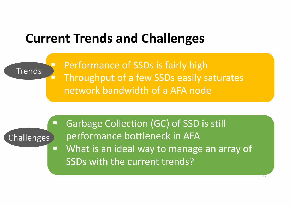
Current Trends and Challenges
§ Performance of SSDs is fairly high§ Throughput of a few SSDs easily saturates
network bandwidth of a AFA node
§ Garbage Collection (GC) of SSD is still performance bottleneck in AFA
§ What is an ideal way to manage an array of SSDs with the current trends?
Trends
Challenges
39
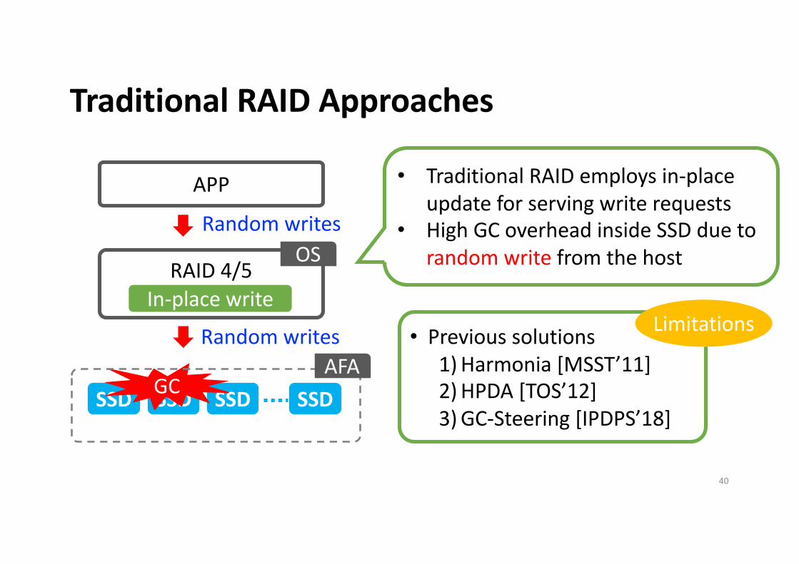
Traditional RAID Approaches
SSD SSD SSDSSD
Random writes
GC
• Previous solutions1) Harmonia [MSST’11]2) HPDA [TOS’12]3) GC-Steering [IPDPS’18]
• Traditional RAID employs in-place update for serving write requests
• High GC overhead inside SSD due to random write from the host
Random writes
RAID 4/5In-place write
OS
APP
AFA
Limitations
40
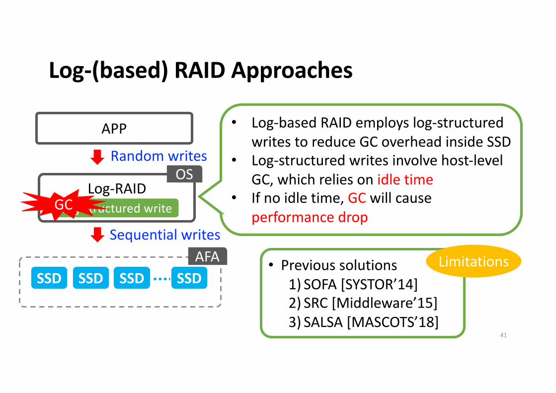
Log-(based) RAID Approaches
SSD SSD SSDSSD
Random writes
Sequential writes
Log-RAIDLog-structured write
OS
APP
AFA
GC
• Log-based RAID employs log-structured writes to reduce GC overhead inside SSD
• Log-structured writes involve host-level GC, which relies on idle time
• If no idle time, GC will cause performance drop
• Previous solutions1) SOFA [SYSTOR’14]2) SRC [Middleware’15]3) SALSA [MASCOTS’18]
Limitations
41
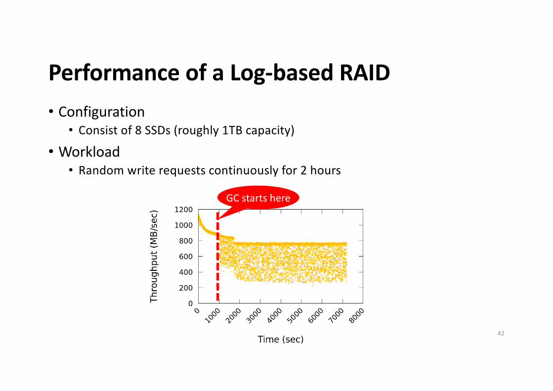
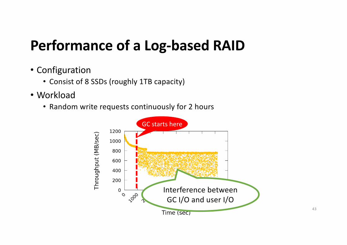
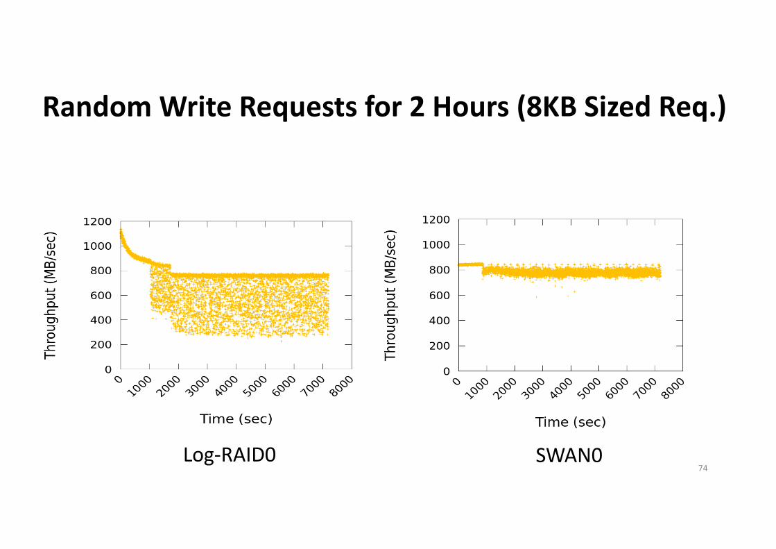
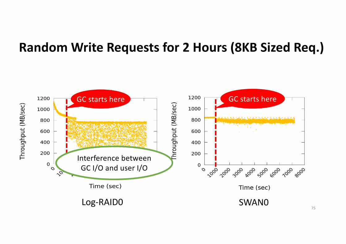
Performance of a Log-based RAID• Configuration
• Consist of 8 SSDs (roughly 1TB capacity)
• Workload• Random write requests continuously for 2 hours
GC starts here
42
Performance of a Log-based RAID• Configuration
• Consist of 8 SSDs (roughly 1TB capacity)
• Workload• Random write requests continuously for 2 hours
GC starts here
Interference between GC I/O and user I/O
43
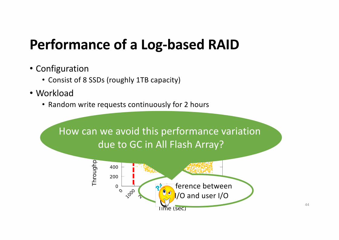
Performance of a Log-based RAID• Configuration
• Consist of 8 SSDs (roughly 1TB capacity)
• Workload• Random write requests continuously for 2 hours
GC starts here
Interference between GC I/O and user I/O
How can we avoid this performance variation due to GC in All Flash Array?
44
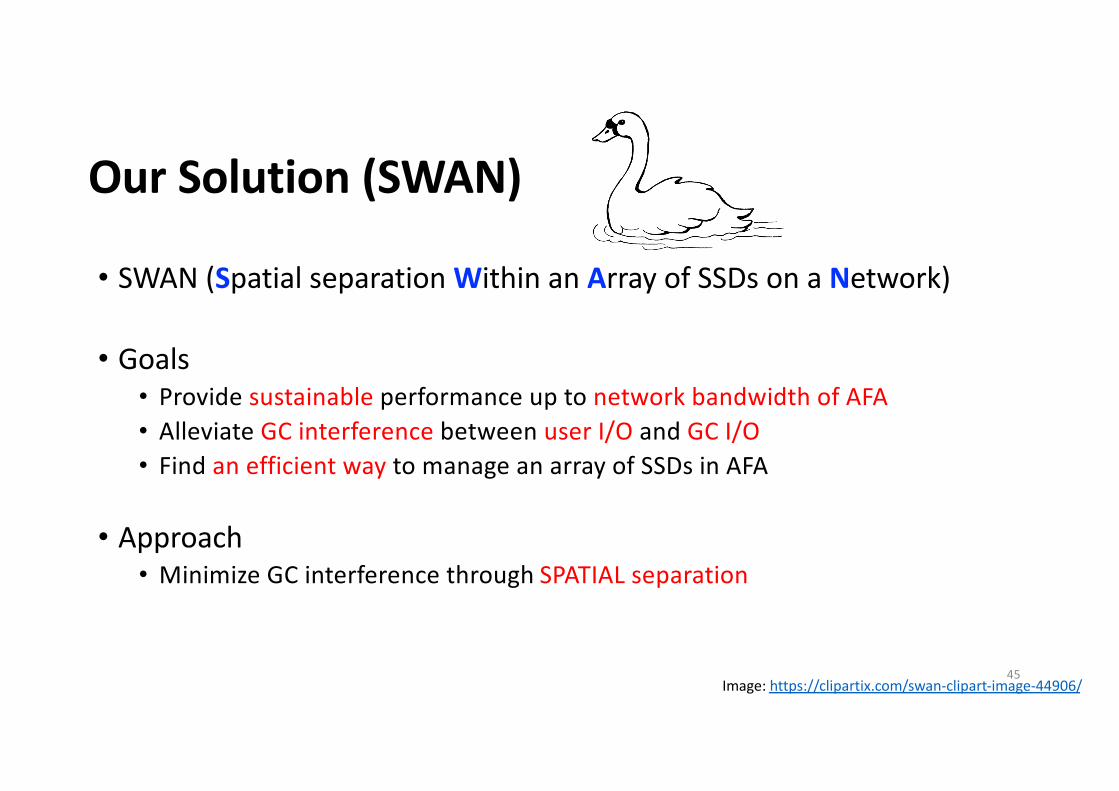
Our Solution (SWAN)
• SWAN (Spatial separation Within an Array of SSDs on a Network)
• Goals• Provide sustainable performance up to network bandwidth of AFA• Alleviate GC interference between user I/O and GC I/O• Find an efficient way to manage an array of SSDs in AFA
• Approach• Minimize GC interference through SPATIAL separation
Image: https://clipartix.com/swan-clipart-image-44906/45
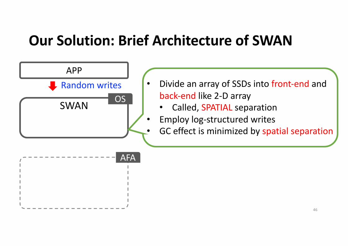
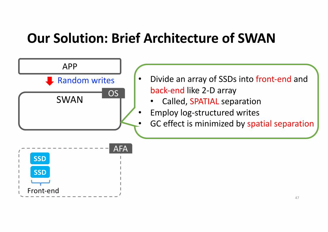
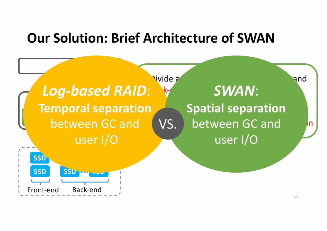
Our Solution: Brief Architecture of SWAN
Random writes
SWAN
• Divide an array of SSDs into front-end and back-end like 2-D array• Called, SPATIAL separation
• Employ log-structured writes• GC effect is minimized by spatial separation
OS
APP
AFA
46
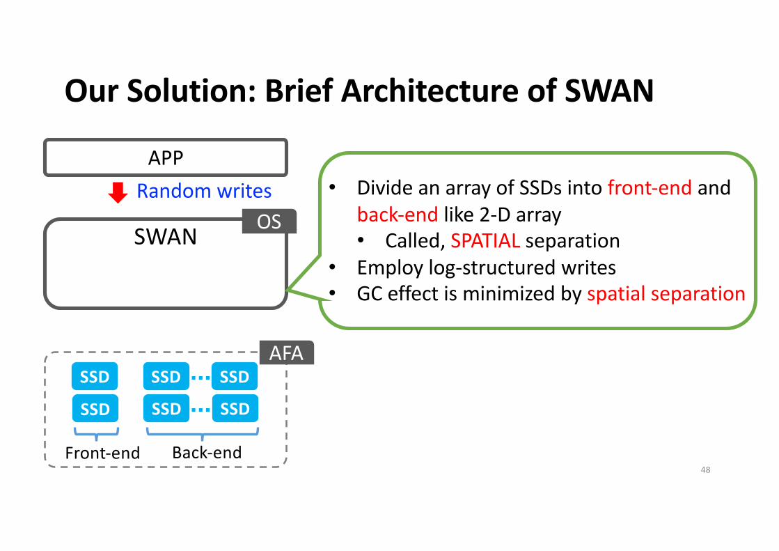
Our Solution: Brief Architecture of SWAN
Random writes
SWAN
SSD
SSD
Front-end
• Divide an array of SSDs into front-end and back-end like 2-D array• Called, SPATIAL separation
• Employ log-structured writes• GC effect is minimized by spatial separation
OS
APP
AFA
47
Our Solution: Brief Architecture of SWAN
Random writes
SWAN
SSD
SSD SSDSSDSSD SSD
Front-end Back-end
• Divide an array of SSDs into front-end and back-end like 2-D array• Called, SPATIAL separation
• Employ log-structured writes• GC effect is minimized by spatial separation
OS
APP
AFA
48
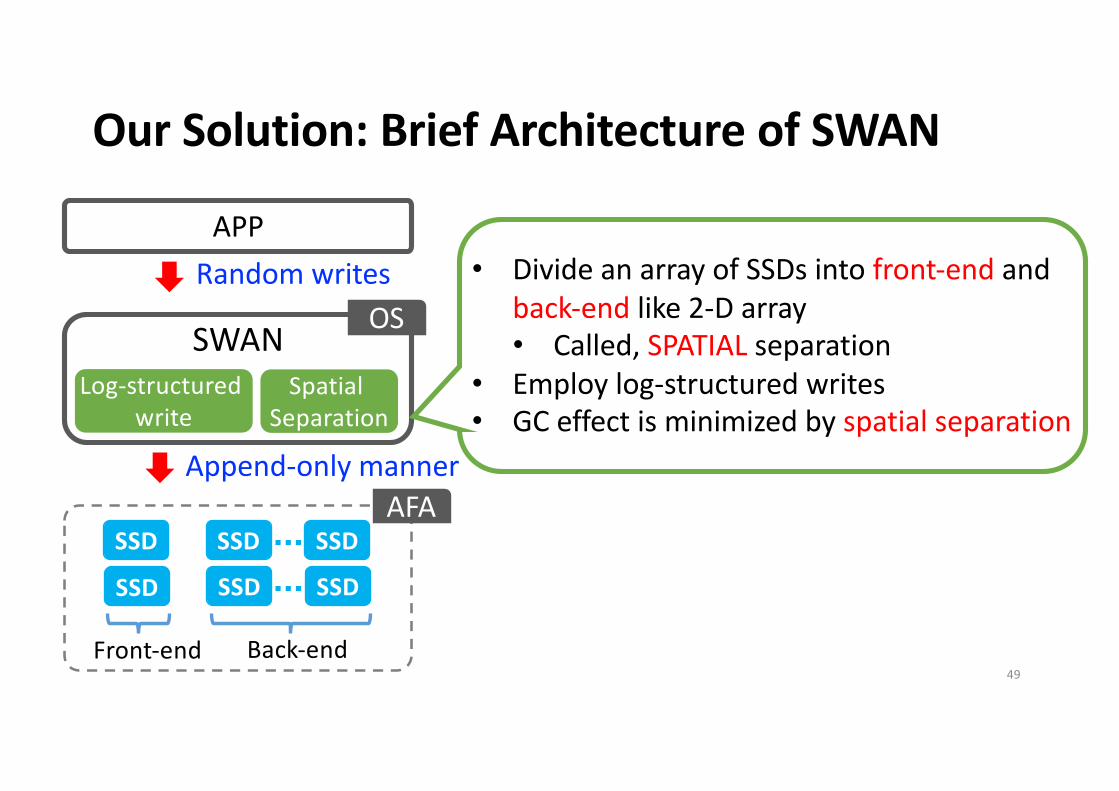
Our Solution: Brief Architecture of SWAN
Random writes
SWANLog-structured
write
Append-only manner
Spatial Separation
SSD
SSD SSDSSDSSD SSD
Front-end Back-end
• Divide an array of SSDs into front-end and back-end like 2-D array• Called, SPATIAL separation
• Employ log-structured writes• GC effect is minimized by spatial separation
OS
APP
AFA
49
Our Solution: Brief Architecture of SWAN
Random writes
SWANLog-structured
write
Append-only manner
Spatial Separation
SSD
SSD SSDSSDSSD SSD
Front-end Back-end
• Divide an array of SSDs into front-end and back-end like 2-D array• Called, SPATIAL separation
• Employ log-structured writes• GC effect is minimized by spatial separation
OS
APP
AFA
50
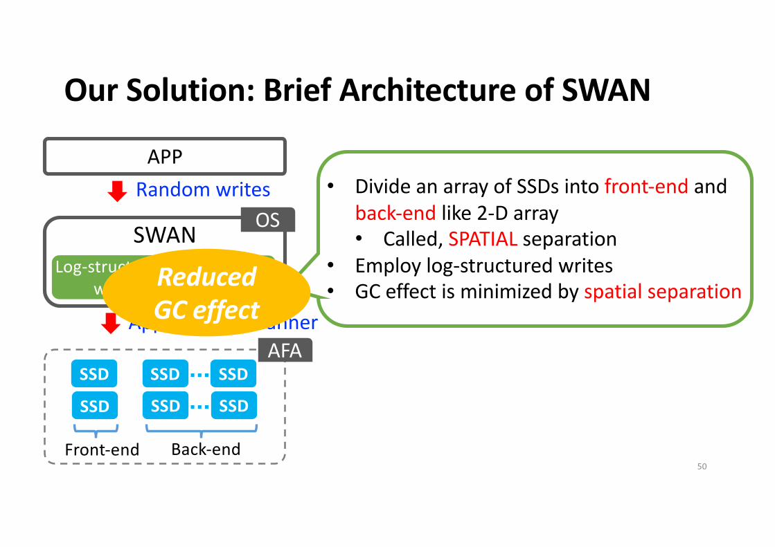
Reduced GC effect
Our Solution: Brief Architecture of SWAN
Random writes
SWANLog-structured
write
Append-only manner
Spatial Separation
SSD
SSD SSDSSDSSD SSD
Front-end Back-end
• Divide an array of SSDs into front-end and back-end like 2-D array• Called, SPATIAL separation
• Employ log-structured writes• GC effect is minimized by spatial separation
OS
APP
AFA
51
Reduced GC effect
Log-based RAID:Temporal separation
between GC and user I/O
SWAN:Spatial separationbetween GC and
user I/OVS.
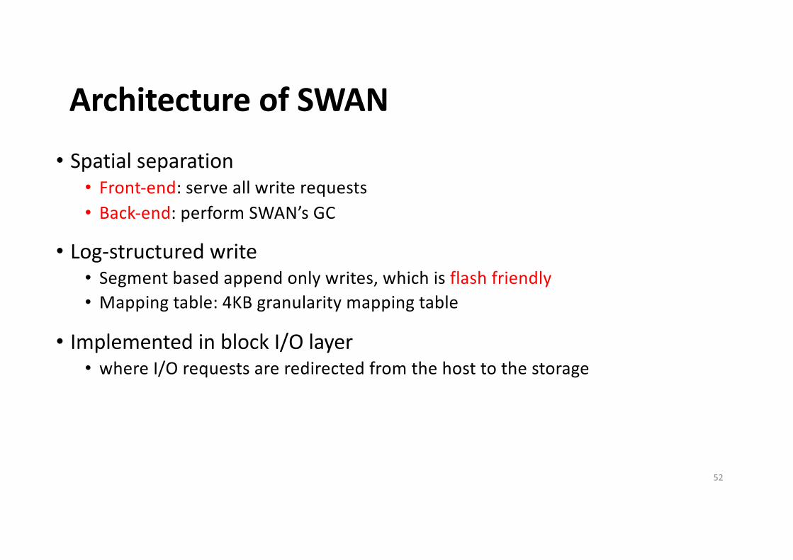
Architecture of SWAN• Spatial separation
• Front-end: serve all write requests• Back-end: perform SWAN’s GC
• Log-structured write• Segment based append only writes, which is flash friendly• Mapping table: 4KB granularity mapping table
• Implemented in block I/O layer• where I/O requests are redirected from the host to the storage
52
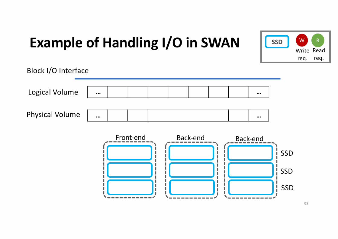
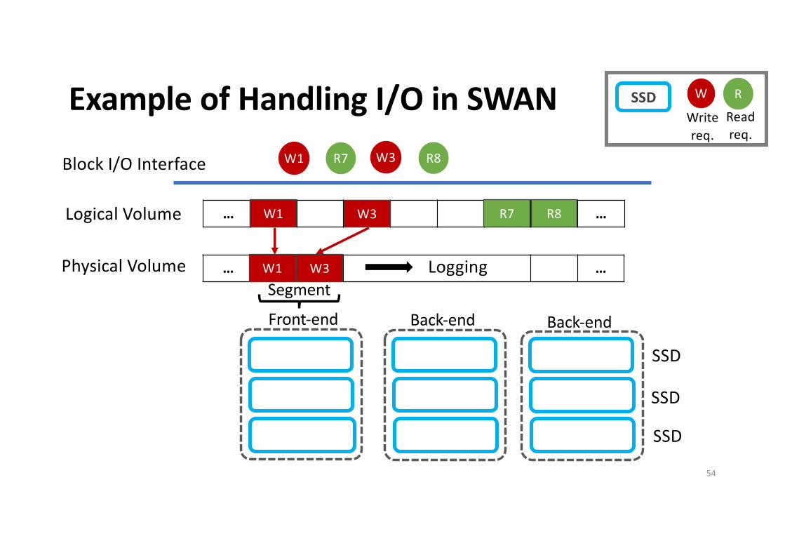
Example of Handling I/O in SWAN
… W1 W3 R7 R8 …
Block I/O Interface
… W1 W3 …
Logical Volume
Physical Volume
SSD
SSD
SSD
Writereq.
Readreq.
W RSSD
Front-end Back-end Back-end
53
Example of Handling I/O in SWAN
… W1 W3 R7 R8 …
Block I/O Interface W1 R7 W3 R8
… W1 W3 …
Logical Volume
Physical Volume LoggingSegment
SSD
SSD
SSD
Writereq.
Readreq.
W RSSD
R7 R8W1 W3
W1 W3
Front-end Back-end Back-end
54
Example of Handling I/O in SWAN
… W1 W3 R7 R8 …
Block I/O Interface W1 R7 W3 R8
… W1 W3 …
Logical Volume
Physical Volume Logging
W1
W3
Parity
Segment
SSD
SSD
SSD
Write
req.
Read
req.
W RSSD
R7
like RAID
parallelism
R8W1 W3
W1 W3
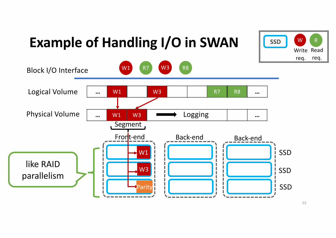
Front-end Back-end Back-end
55
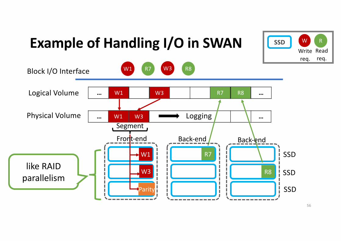
Example of Handling I/O in SWAN
… W1 W3 R7 R8 …
Block I/O Interface W1 R7 W3 R8
… W1 W3 …
Logical Volume
Physical Volume Logging
W1
W3
Parity
Segment
R7
R8
SSD
SSD
SSD
Write
req.
Read
req.
W RSSD
R7
like RAID
parallelism
R8W1 W3
W1 W3
Front-end Back-end Back-end
56
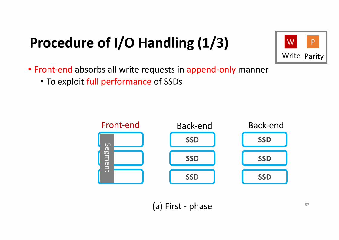
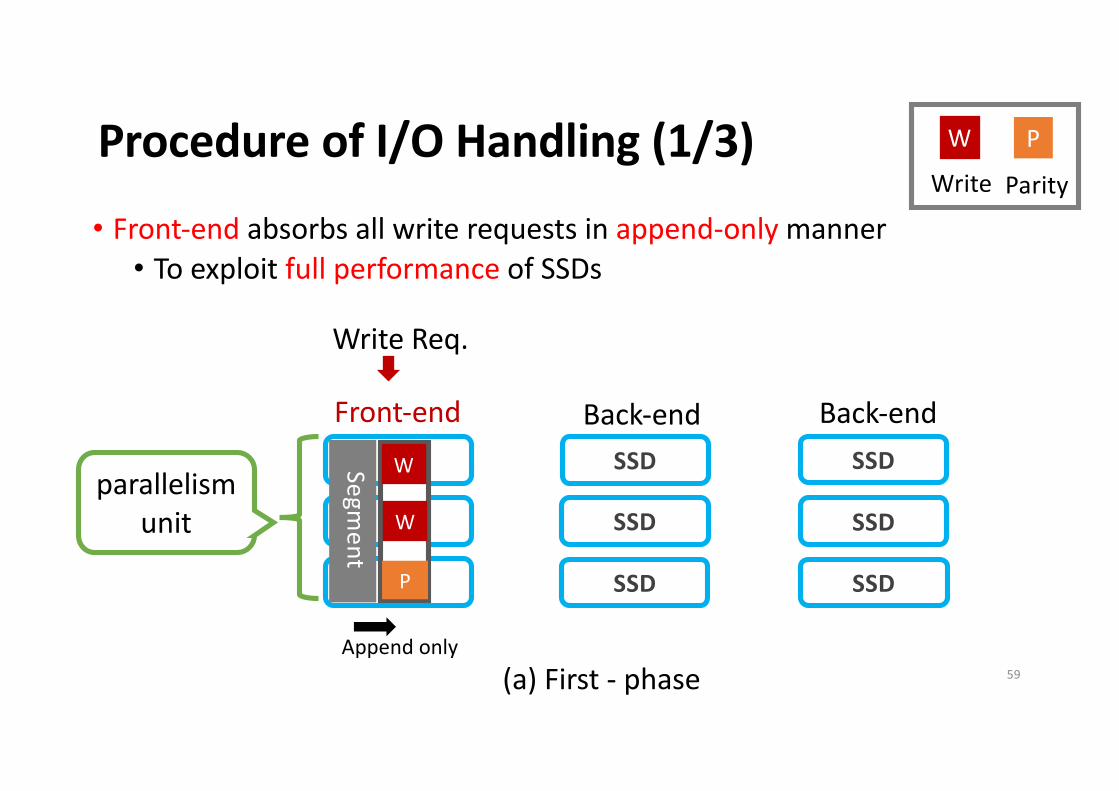
Procedure of I/O Handling (1/3)
SSD
SSD
SSD
SSD
SSD
SSD
Front-end Back-end Back-end
Segment
(a) First - phase
• Front-end absorbs all write requests in append-only manner• To exploit full performance of SSDs
Parity
PW
Write
57
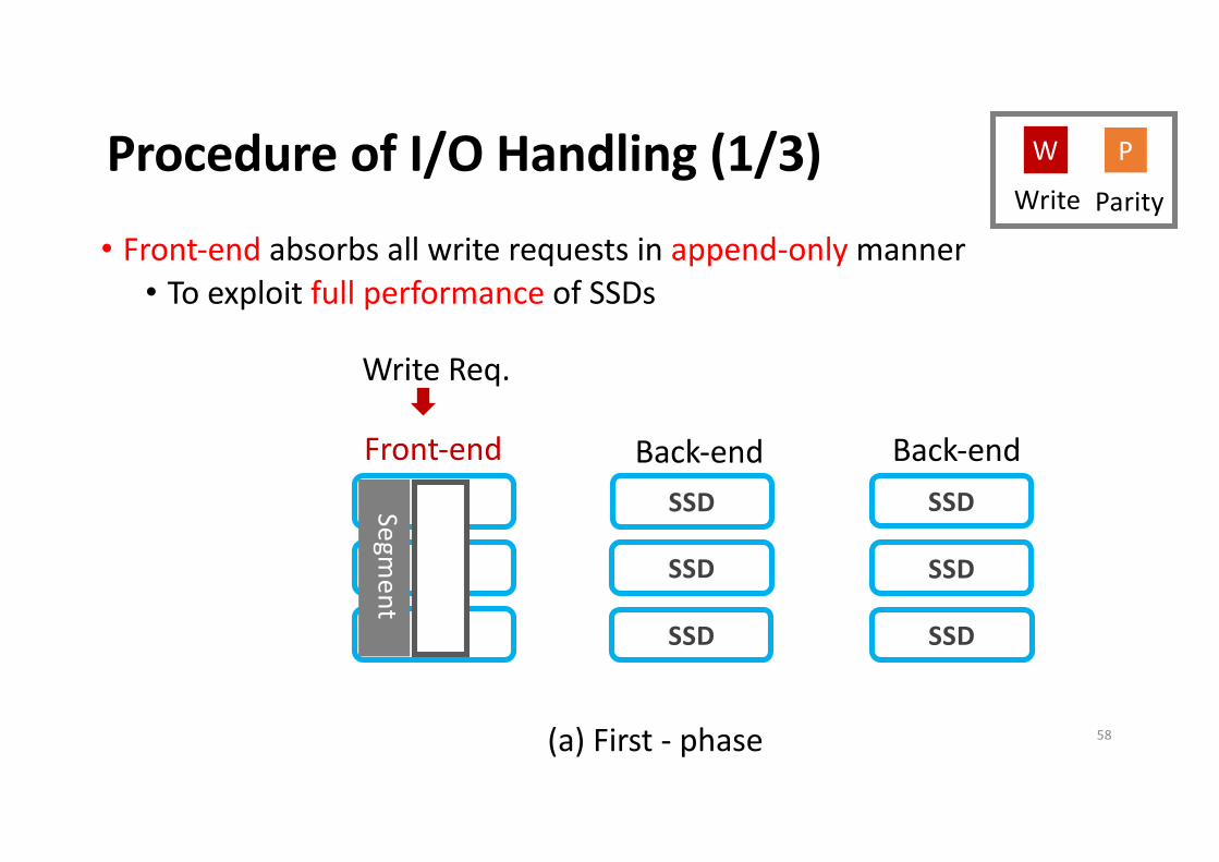
Procedure of I/O Handling (1/3)
SSD
SSD
SSD
SSD
SSD
SSD
Front-end Back-end Back-end
Segment
Write Req.
(a) First - phase
• Front-end absorbs all write requests in append-only manner• To exploit full performance of SSDs
Parity
PW
Write
58
Procedure of I/O Handling (1/3)
SSD
SSD
SSD
SSD
SSD
SSD
Front-end Back-end Back-end
Segment
W
W
P
Write Req.
Append only(a) First - phase
• Front-end absorbs all write requests in append-only manner• To exploit full performance of SSDs
parallelism unit
Parity
PW
Write
59
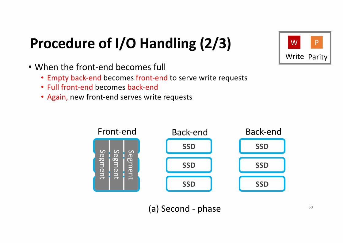
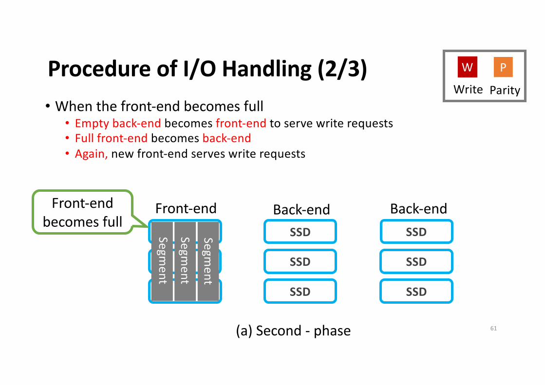
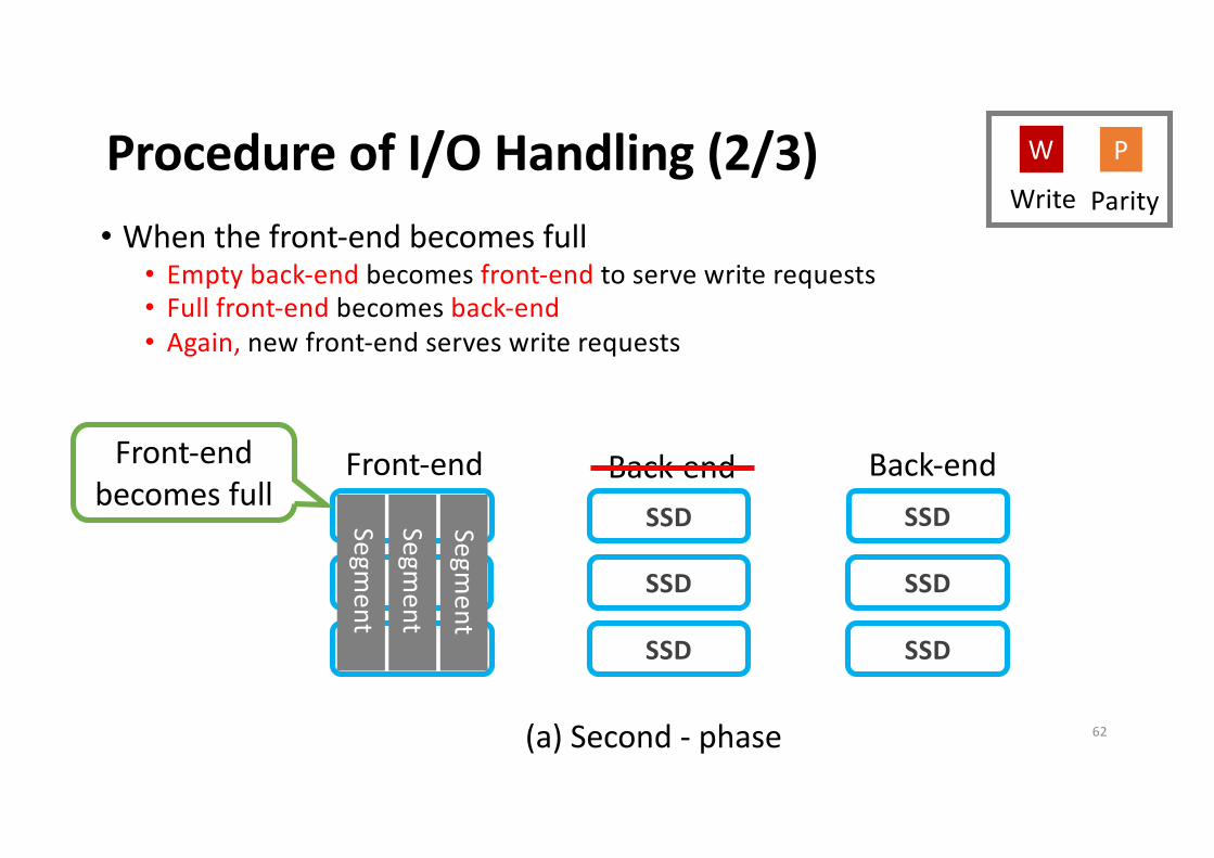
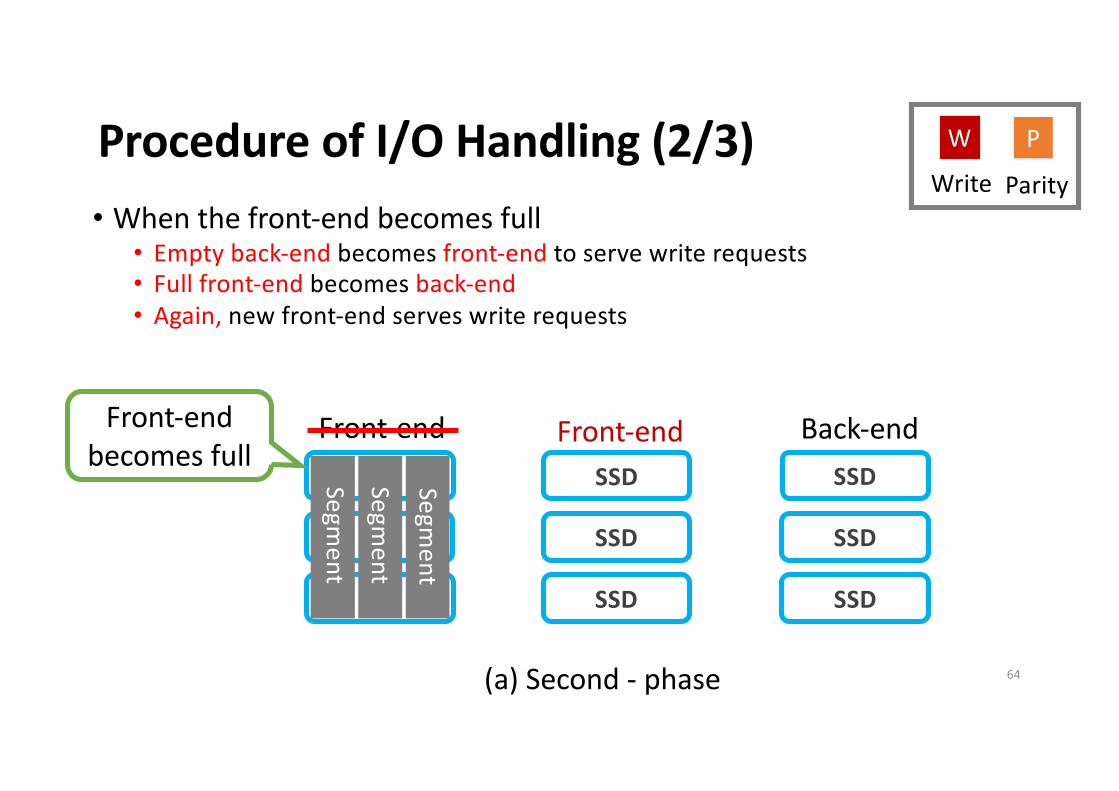
Procedure of I/O Handling (2/3)
SSD
SSD
SSD
SSD
SSD
SSD
Front-end Back-end Back-end
Segment
(a) Second - phase
• When the front-end becomes full• Empty back-end becomes front-end to serve write requests• Full front-end becomes back-end• Again, new front-end serves write requests
Parity
PW
Write
Segment
Segment
60
Procedure of I/O Handling (2/3)
SSD
SSD
SSD
SSD
SSD
SSD
Front-end Back-end Back-end
Segment
(a) Second - phase
• When the front-end becomes full• Empty back-end becomes front-end to serve write requests• Full front-end becomes back-end• Again, new front-end serves write requests
Parity
PW
Write
Segment
Segment
Front-end becomes full
61
Procedure of I/O Handling (2/3)
SSD
SSD
SSD
SSD
SSD
SSD
Front-end Back-end Back-end
Segment
(a) Second - phase
• When the front-end becomes full• Empty back-end becomes front-end to serve write requests• Full front-end becomes back-end• Again, new front-end serves write requests
Parity
PW
Write
Segment
Segment
Front-end becomes full
62

Procedure of I/O Handling (2/3)
SSD
SSD
SSD
SSD
SSD
SSD
Front-end Back-end Back-end
Segment
(a) Second - phase
• When the front-end becomes full• Empty back-end becomes front-end to serve write requests• Full front-end becomes back-end• Again, new front-end serves write requests
Parity
PW
Write
Front-end
Segment
Segment
Front-end becomes full
63
Procedure of I/O Handling (2/3)
SSD
SSD
SSD
SSD
SSD
SSD
Front-end Back-end Back-end
Segment
(a) Second - phase
• When the front-end becomes full• Empty back-end becomes front-end to serve write requests• Full front-end becomes back-end• Again, new front-end serves write requests
Parity
PW
Write
Front-end
Segment
Segment
Front-end becomes full
64

Procedure of I/O Handling (2/3)
SSD
SSD
SSD
SSD
SSD
SSD
Front-end Back-end Back-end
Segment
(a) Second - phase
• When the front-end becomes full• Empty back-end becomes front-end to serve write requests• Full front-end becomes back-end• Again, new front-end serves write requests
Parity
PW
Write
Front-endBack-end
Segment
Segment
Front-end becomes full
65
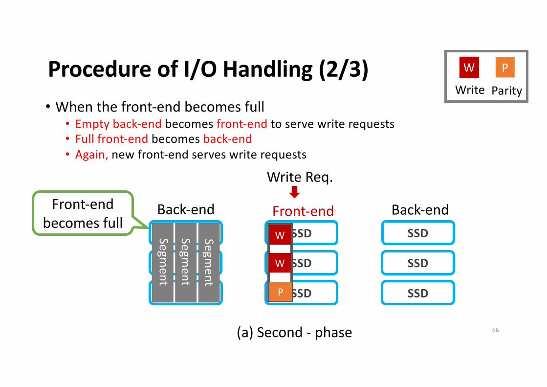
Procedure of I/O Handling (2/3)
SSD
SSD
SSD
SSD
SSD
SSD
Front-end Back-end Back-end
Segment
W
W
P
Write Req.
(a) Second - phase
• When the front-end becomes full• Empty back-end becomes front-end to serve write requests• Full front-end becomes back-end• Again, new front-end serves write requests
Parity
PW
Write
Front-endBack-end
Segment
Segment
Front-end becomes full
66

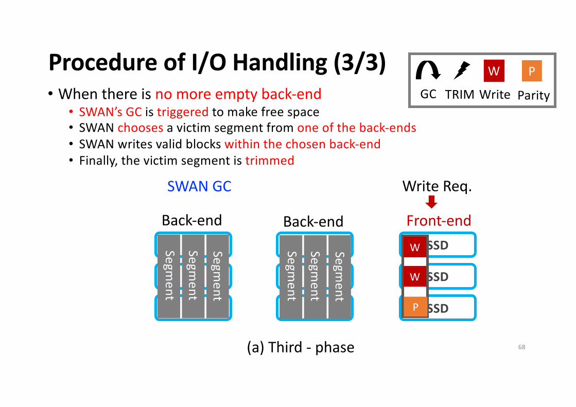
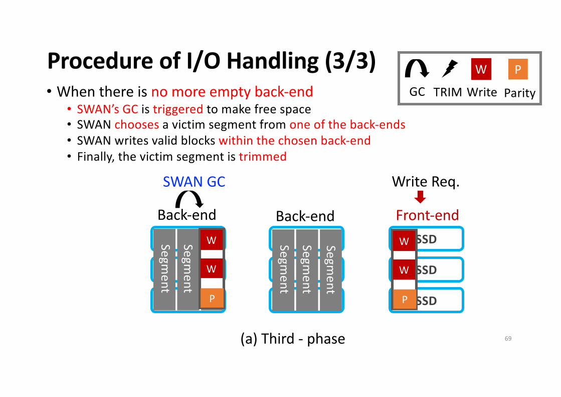
Procedure of I/O Handling (3/3)
SSD
SSD
SSD
SSD
SSD
SSD
Back-end Back-end Front-end
Se
gm
en
t
W
W
P
Write Req.
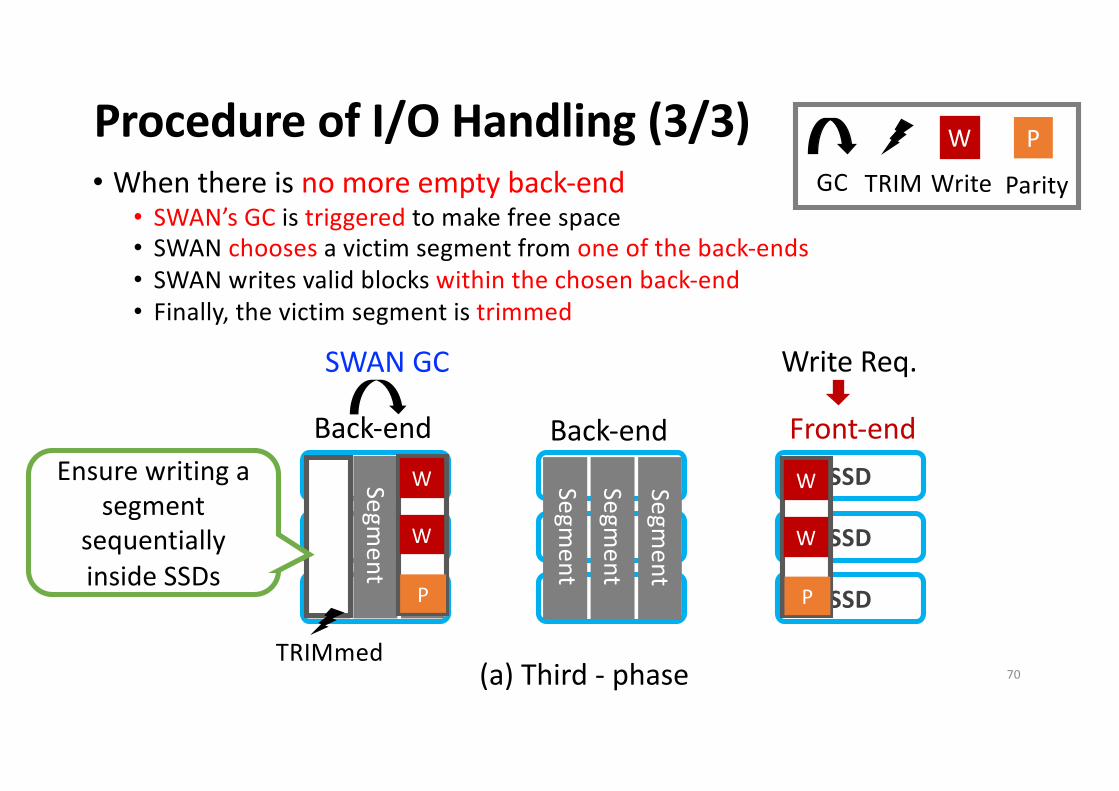
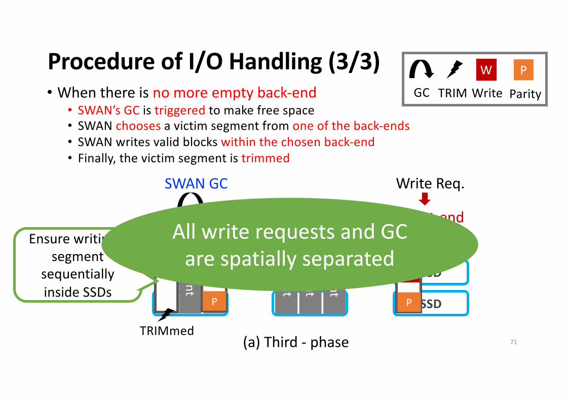
(a) Third - phase
• When there is no more empty back-end
• SWAN’s GC is triggered to make free space
• SWAN chooses a victim segment from one of the back-ends
• SWAN writes valid blocks within the chosen back-end
• Finally, the victim segment is trimmed
Parity
PW
Write
Se
gm
en
t
Se
gm
en
t
Se
gm
en
t
Se
gm
en
t
Se
gm
en
t
SWAN GC
GC TRIM
67
Procedure of I/O Handling (3/3)
SSD
SSD
SSD
SSD
SSD
SSD
Back-end Back-end Front-end
Se
gm
en
t
W
W
P
Write Req.
(a) Third - phase
• When there is no more empty back-end
• SWAN’s GC is triggered to make free space
• SWAN chooses a victim segment from one of the back-ends
• SWAN writes valid blocks within the chosen back-end
• Finally, the victim segment is trimmed
Parity
PW
Write
Se
gm
en
t
Se
gm
en
t
Se
gm
en
t
Se
gm
en
t
Se
gm
en
t
SWAN GC
GC TRIM
68
Procedure of I/O Handling (3/3)
SSD
SSD
SSD
SSD
SSD
SSD
Back-end Back-end Front-end
Se
gm
en
t
W
W
P
Write Req.
(a) Third - phase
• When there is no more empty back-end
• SWAN’s GC is triggered to make free space
• SWAN chooses a victim segment from one of the back-ends
• SWAN writes valid blocks within the chosen back-end
• Finally, the victim segment is trimmed
Parity
PW
Write
Se
gm
en
t
Se
gm
en
t
Se
gm
en
t
Se
gm
en
t
Se
gm
en
t
SWAN GC
GC TRIM
W
W
P
69
Procedure of I/O Handling (3/3)
SSD
SSD
SSD
SSD
SSD
SSD
Back-end Back-end Front-end
Se
gm
en
t
W
W
P
Write Req.
(a) Third - phase
• When there is no more empty back-end
• SWAN’s GC is triggered to make free space
• SWAN chooses a victim segment from one of the back-ends
• SWAN writes valid blocks within the chosen back-end
• Finally, the victim segment is trimmed
Parity
PW
Write
Se
gm
en
t
Se
gm
en
t
Se
gm
en
t
Se
gm
en
t
Se
gm
en
t
SWAN GC
TRIMmed
Ensure writing a
segment
sequentially
inside SSDs
GC TRIM
W
W
P
70
Procedure of I/O Handling (3/3)
SSD
SSD
SSD
SSD
SSD
SSD
Back-end Back-end Front-end
Se
gm
en
t
W
W
P
Write Req.
(a) Third - phase
• When there is no more empty back-end
• SWAN’s GC is triggered to make free space
• SWAN chooses a victim segment from one of the back-ends
• SWAN writes valid blocks within the chosen back-end
• Finally, the victim segment is trimmed
Parity
PW
Write
Se
gm
en
t
Se
gm
en
t
Se
gm
en
t
Se
gm
en
t
Se
gm
en
t
SWAN GC
TRIMmed
Ensure writing a
segment
sequentially
inside SSDs
GC TRIM
W
W
P
All write requests and GC
are spatially separated
71
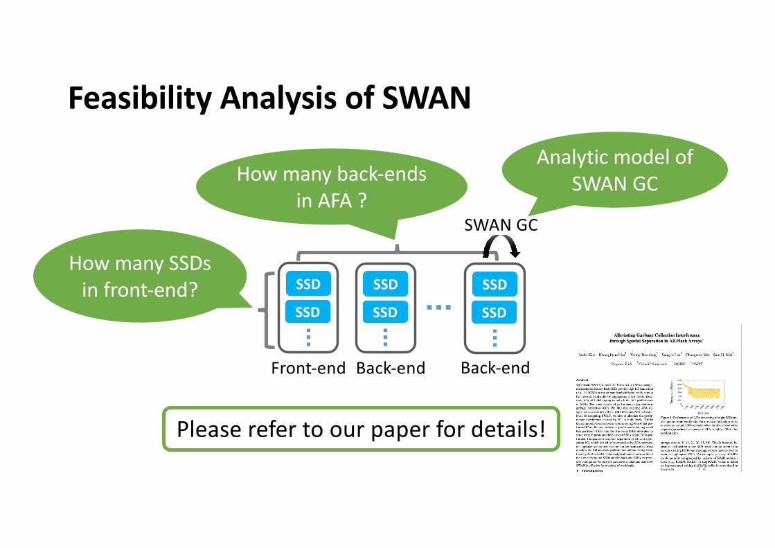
Feasibility Analysis of SWAN
Front-end Back-end Back-end
SSD
SSD
SSD
SSD
SSD
SSDHow many SSDs
in front-end?
How many back-ends in AFA ?
Please refer to our paper for details!
SWAN GC
Analytic model of SWAN GC
72
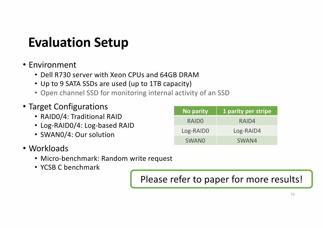
Evaluation Setup• Environment
• Dell R730 server with Xeon CPUs and 64GB DRAM
• Up to 9 SATA SSDs are used (up to 1TB capacity)
• Open channel SSD for monitoring internal activity of an SSD
• Target Configurations• RAID0/4: Traditional RAID
• Log-RAID0/4: Log-based RAID
• SWAN0/4: Our solution
• Workloads• Micro-benchmark: Random write request
• YCSB C benchmark
Please refer to paper for more results!
73
No parity 1 parity per stripeRAID0 RAID4
Log-RAID0 Log-RAID4
SWAN0 SWAN4
Random Write Requests for 2 Hours (8KB Sized Req.)
SWAN0Log-RAID074
Random Write Requests for 2 Hours (8KB Sized Req.)
SWAN0Log-RAID0
GC starts here GC starts here
Interference between GC I/O and user I/O
75
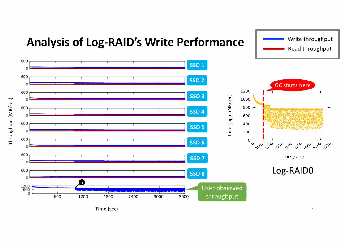
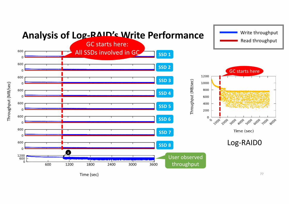
Analysis of Log-RAID’s Write Performance
a
Thro
ughp
ut (M
B/se
c)
Time (sec)
600 1200 1800 2400 3000 3600
SSD1
SSD2
SSD3
SSD4
SSD5
SSD6
SSD7
SSD8
USER
SSD 1
SSD 2
SSD 3
SSD 4
SSD 5
SSD 6
SSD 7
SSD 8
GC starts here
Log-RAID0
User observed throughput
Write throughputRead throughput
76
Analysis of Log-RAID’s Write Performance
a
Thro
ughp
ut (M
B/se
c)
Time (sec)
600 1200 1800 2400 3000 3600
SSD1
SSD2
SSD3
SSD4
SSD5
SSD6
SSD7
SSD8
USER
SSD 1
SSD 2
SSD 3
SSD 4
SSD 5
SSD 6
SSD 7
SSD 8
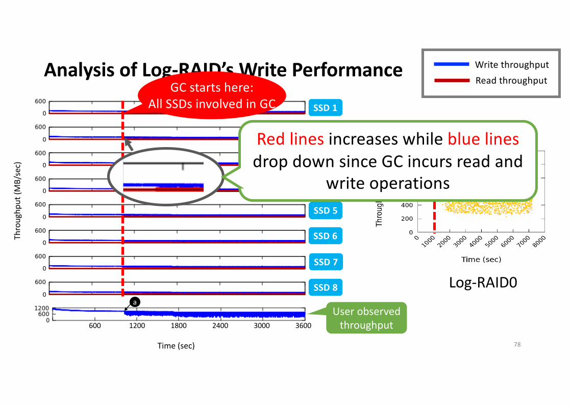
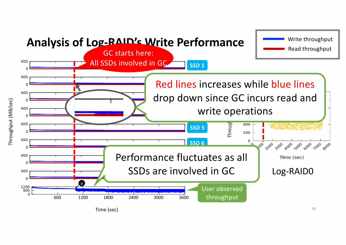
GC starts here:All SSDs involved in GC
GC starts here
Log-RAID0
User observed throughput
Write throughputRead throughput
77
Analysis of Log-RAID’s Write Performance
a
Thro
ughp
ut (M
B/se
c)
Time (sec)
600 1200 1800 2400 3000 3600
SSD1
SSD2
SSD3
SSD4
SSD5
SSD6
SSD7
SSD8
USER
SSD 1
SSD 2
SSD 3
SSD 4
SSD 5
SSD 6
SSD 7
SSD 8
GC starts here:All SSDs involved in GC
GC starts here
Log-RAID0
User observed throughput
Write throughputRead throughput
Red lines increases while blue linesdrop down since GC incurs read and
write operations
78
Analysis of Log-RAID’s Write Performance
a
Thro
ughp
ut (M
B/se
c)
Time (sec)
600 1200 1800 2400 3000 3600
SSD1
SSD2
SSD3
SSD4
SSD5
SSD6
SSD7
SSD8
USER
SSD 1
SSD 2
SSD 3
SSD 4
SSD 5
SSD 6
SSD 7
SSD 8
GC starts here:All SSDs involved in GC
GC starts here
Log-RAID0
User observed throughput
Write throughputRead throughput
Performance fluctuates as all SSDs are involved in GC
Red lines increases while blue linesdrop down since GC incurs read and
write operations
79
Analysis of SWAN’s Write Performance
b
c
Thro
ughp
ut (M
B/se
c)
Time (sec)
600 1200 1800 2400 3000 3600
SSD1
SSD2
SSD3
SSD4
SSD5
SSD6
SSD7
SSD8
USER
SSD 1
SSD 2
SSD 3
SSD 4
SSD 5
SSD 6
SSD 7
SSD 8
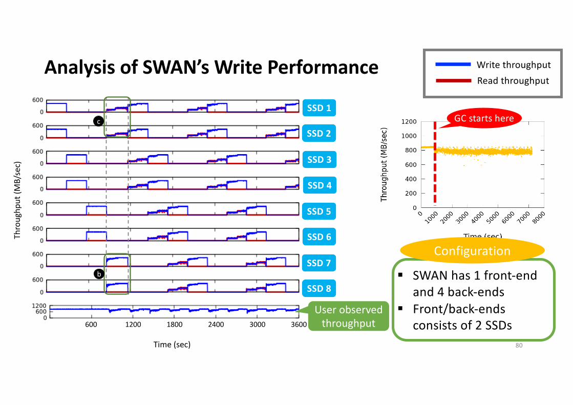
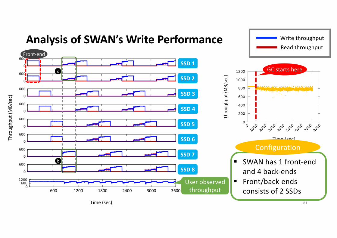
GC starts here
User observed throughput
Write throughputRead throughput
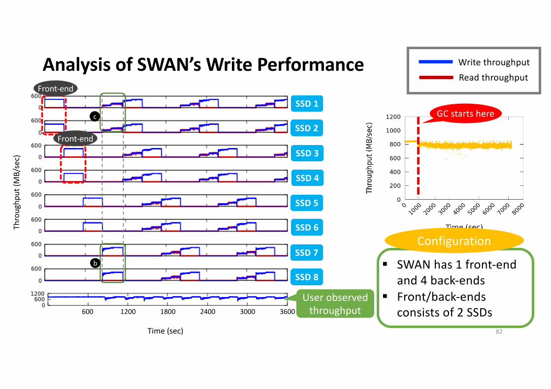
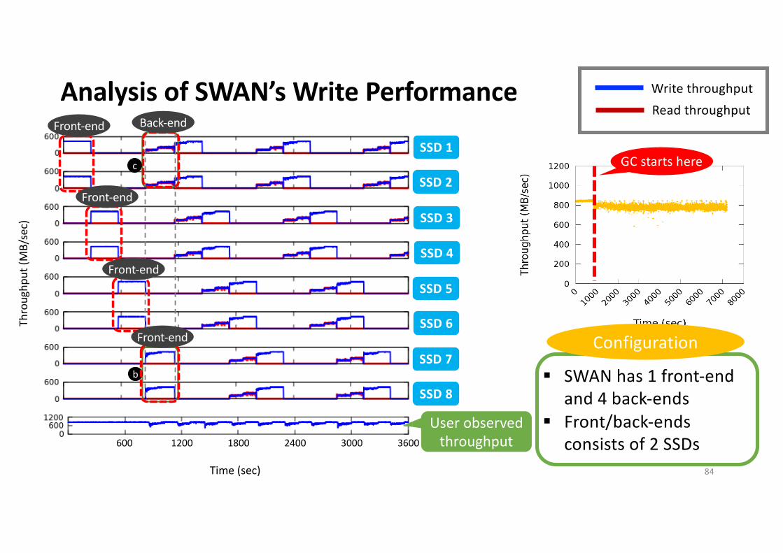
§ SWAN has 1 front-end and 4 back-ends
§ Front/back-ends consists of 2 SSDs
Configuration
80
Analysis of SWAN’s Write Performance
b
c
Thro
ughp
ut (M
B/se
c)
Time (sec)
600 1200 1800 2400 3000 3600
SSD1
SSD2
SSD3
SSD4
SSD5
SSD6
SSD7
SSD8
USER
SSD 1
SSD 2
SSD 3
SSD 4
SSD 5
SSD 6
SSD 7
SSD 8
GC starts here
User observed throughput
Front-end
Write throughputRead throughput
§ SWAN has 1 front-end and 4 back-ends
§ Front/back-ends consists of 2 SSDs
Configuration
81
Analysis of SWAN’s Write Performance
b
c
Thro
ughp
ut (M
B/se
c)
Time (sec)
600 1200 1800 2400 3000 3600
SSD1
SSD2
SSD3
SSD4
SSD5
SSD6
SSD7
SSD8
USER
SSD 1
SSD 2
SSD 3
SSD 4
SSD 5
SSD 6
SSD 7
SSD 8
GC starts here
User observed throughput
Front-end
Front-end
Write throughputRead throughput
§ SWAN has 1 front-end and 4 back-ends
§ Front/back-ends consists of 2 SSDs
Configuration
82
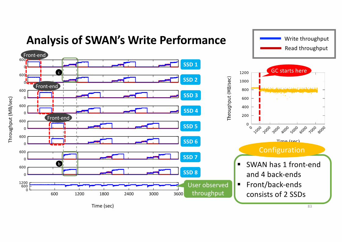
Analysis of SWAN’s Write Performance
b
c
Thro
ughp
ut (M
B/se
c)
Time (sec)
600 1200 1800 2400 3000 3600
SSD1
SSD2
SSD3
SSD4
SSD5
SSD6
SSD7
SSD8
USER
SSD 1
SSD 2
SSD 3
SSD 4
SSD 5
SSD 6
SSD 7
SSD 8
GC starts here
User observed throughput
Front-end
Front-end
Front-end
Write throughputRead throughput
§ SWAN has 1 front-end and 4 back-ends
§ Front/back-ends consists of 2 SSDs
Configuration
83
Analysis of SWAN’s Write Performance
b
c
Thro
ughp
ut (M
B/se
c)
Time (sec)
600 1200 1800 2400 3000 3600
SSD1
SSD2
SSD3
SSD4
SSD5
SSD6
SSD7
SSD8
USER
SSD 1
SSD 2
SSD 3
SSD 4
SSD 5
SSD 6
SSD 7
SSD 8
GC starts here
User observed throughput
Front-end
Front-end
Front-end
Front-end
Back-end
Write throughputRead throughput
§ SWAN has 1 front-end and 4 back-ends
§ Front/back-ends consists of 2 SSDs
Configuration
84
Analysis of SWAN’s Write Performance
b
c
Thro
ughp
ut (M
B/se
c)
Time (sec)
600 1200 1800 2400 3000 3600
SSD1
SSD2
SSD3
SSD4
SSD5
SSD6
SSD7
SSD8
USER
SSD 1
SSD 2
SSD 3
SSD 4
SSD 5
SSD 6
SSD 7
SSD 8
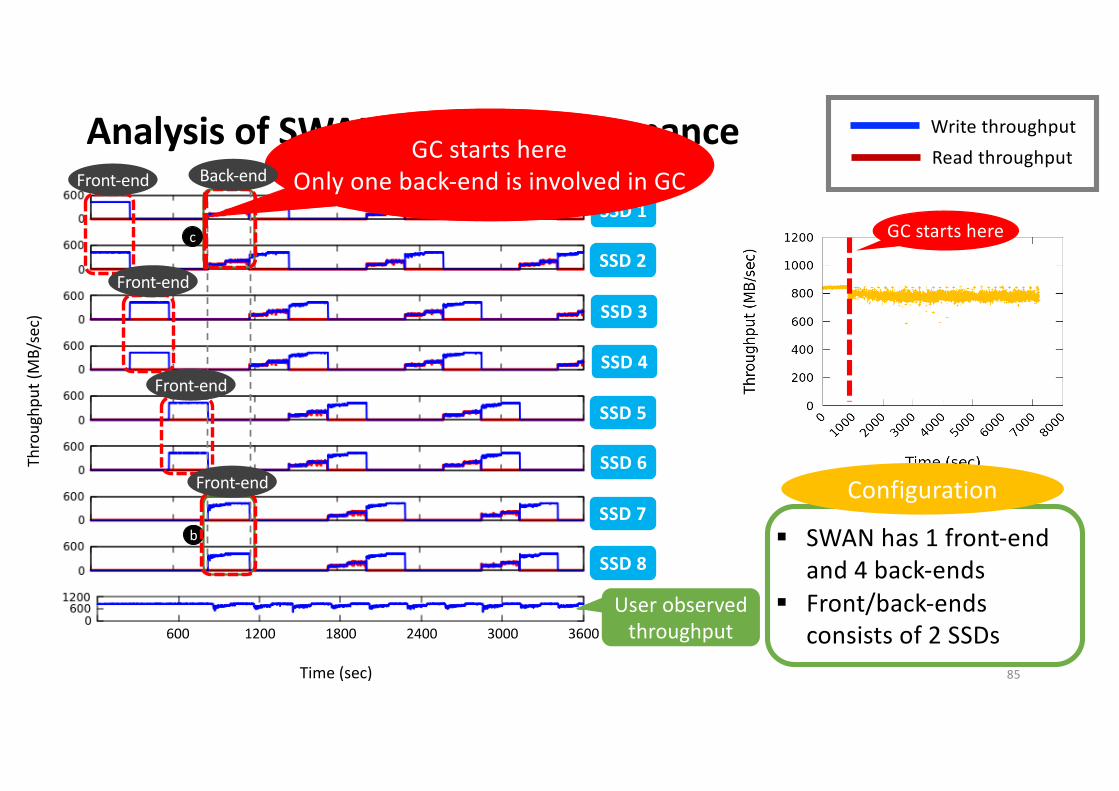
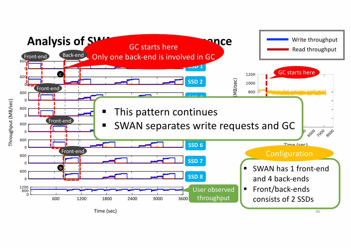
GC starts here
GC starts hereOnly one back-end is involved in GC
User observed throughput
Front-end
Front-end
Front-end
Front-end
Back-end
Write throughputRead throughput
§ SWAN has 1 front-end and 4 back-ends
§ Front/back-ends consists of 2 SSDs
Configuration
85
Analysis of SWAN’s Write Performance
b
c
Thro
ughp
ut (M
B/se
c)
Time (sec)
600 1200 1800 2400 3000 3600
SSD1
SSD2
SSD3
SSD4
SSD5
SSD6
SSD7
SSD8
USER
SSD 1
SSD 2
SSD 3
SSD 4
SSD 5
SSD 6
SSD 7
SSD 8
GC starts here
GC starts hereOnly one back-end is involved in GC
User observed throughput
Front-end
Front-end
Front-end
Front-end
Back-end
Write throughput
Read throughput
§ SWAN has 1 front-end and 4 back-ends
§ Front/back-ends consists of 2 SSDs
Configuration
§ This pattern continues§ SWAN separates write requests and GC
86
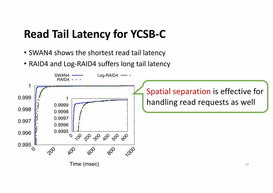
Read Tail Latency for YCSB-C• SWAN4 shows the shortest read tail latency• RAID4 and Log-RAID4 suffers long tail latency
0.995
0.996
0.997
0.998
0.999
1
0 20
0 40
0 60
0 80
0 10
00
Time (msec)
SWAN4RAID4
Log-RAID4
0.9995 0.9996 0.9997 0.9998 0.9999
1
0 10
0 20
0 30
0 40
0 50
0 60
0
Spatial separation is effective for handling read requests as well
87
Benefits with Simpler SSDs• SWAN can saves cost and power consumption w/o
compromising performance by adopting simpler SSDs1) Smaller DRAM size2) Smaller over-provisioning space (OPS)3) Block or segment level FTL instead of page-level FTL
88
SWAN sequentially writes data to segments and TRIMs a large chunk
of data in the same segment at once
Conclusion• Provide full write performance of an array of SSDs up to network
bandwidth limit
• Alleviate GC interference through separation of I/O induced by application and GC of All Flash Array
• Introduce an efficient way to manage SSDs in All Flash Array
89
Thanks for attention!Q&A
Backup slides
90
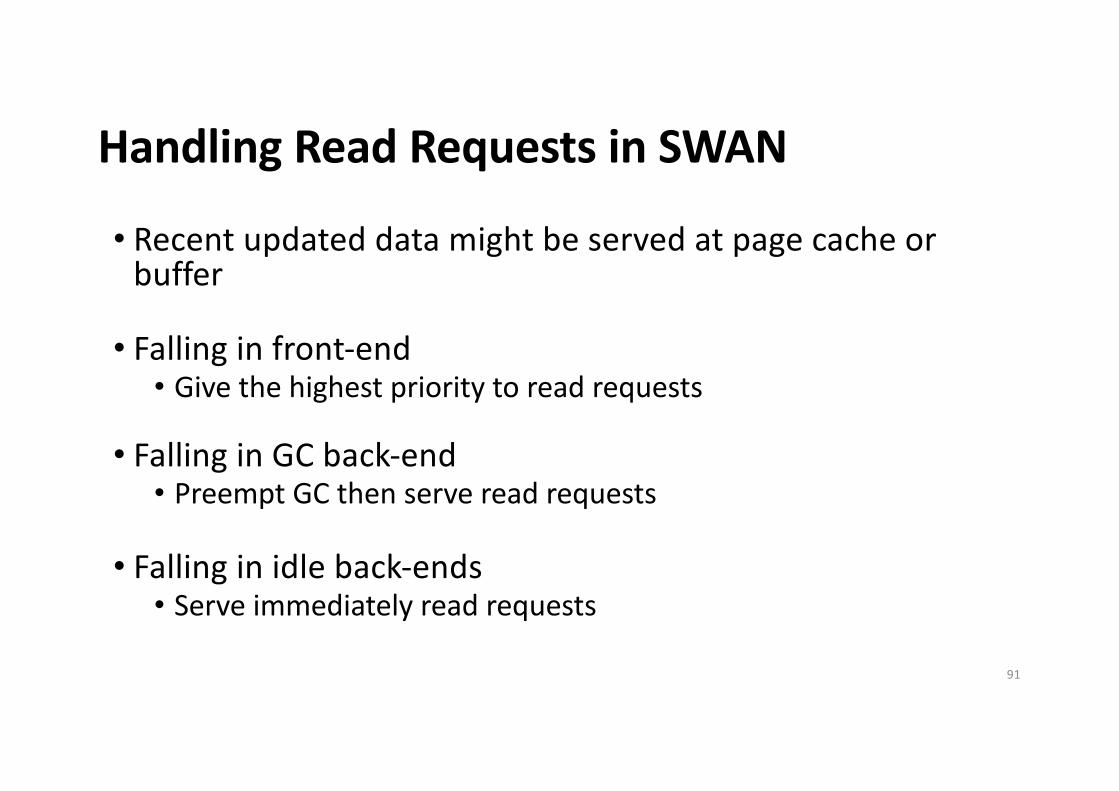
Handling Read Requests in SWAN
• Recent updated data might be served at page cache or buffer
• Falling in front-end• Give the highest priority to read requests
• Falling in GC back-end• Preempt GC then serve read requests
• Falling in idle back-ends• Serve immediately read requests
91
GC overhead inside SSDs
• GC overhead should be very low inside SSDs• SWAN writes all the data in a segment-based append-
only manner• Then, SWAN gives TRIMs to ensure writing a segment
sequentially inside SSDs
92
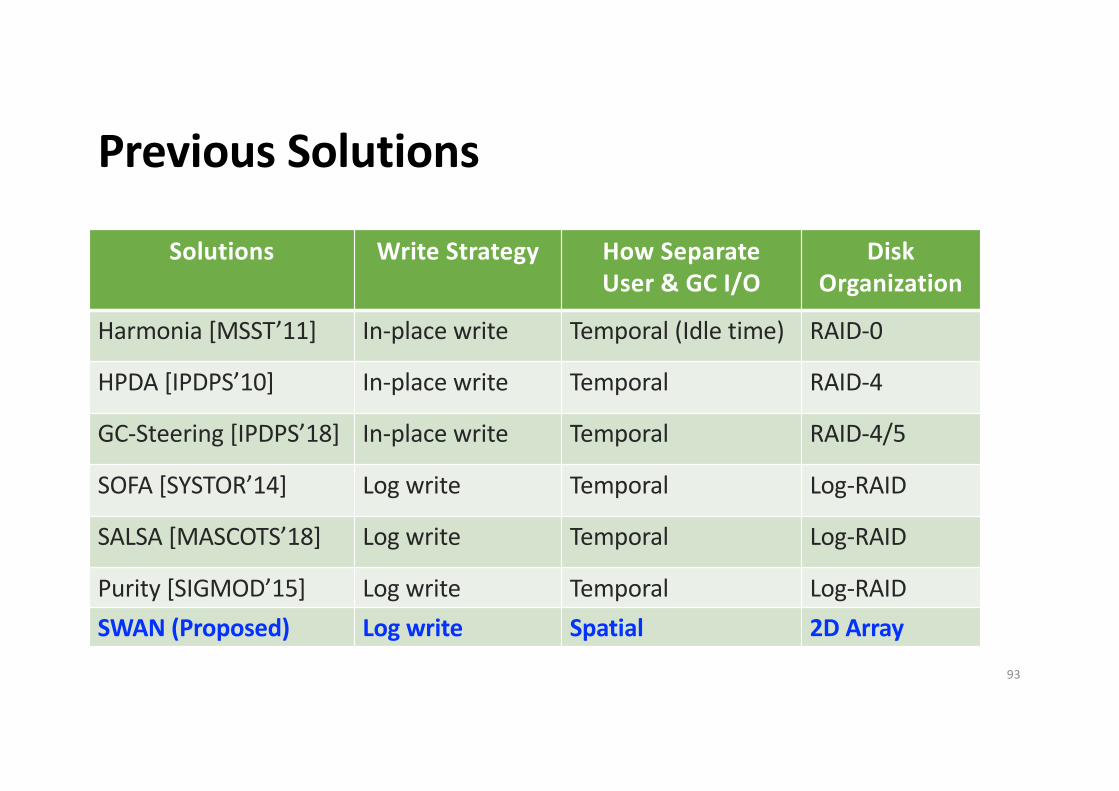
Previous Solutions
Solutions Write Strategy How Separate User & GC I/O
Disk Organization
Harmonia [MSST’11] In-place write Temporal (Idle time) RAID-0
HPDA [IPDPS’10] In-place write Temporal RAID-4
GC-Steering [IPDPS’18] In-place write Temporal RAID-4/5
SOFA [SYSTOR’14] Log write Temporal Log-RAID
SALSA [MASCOTS’18] Log write Temporal Log-RAID
Purity [SIGMOD’15] Log write Temporal Log-RAIDSWAN (Proposed) Log write Spatial 2D Array
93