Embed Size (px)
Citation preview
High-Performance Alloys for Automotive Engineering
Zuudee Super Alloys www.TiNiAlloys.com
2
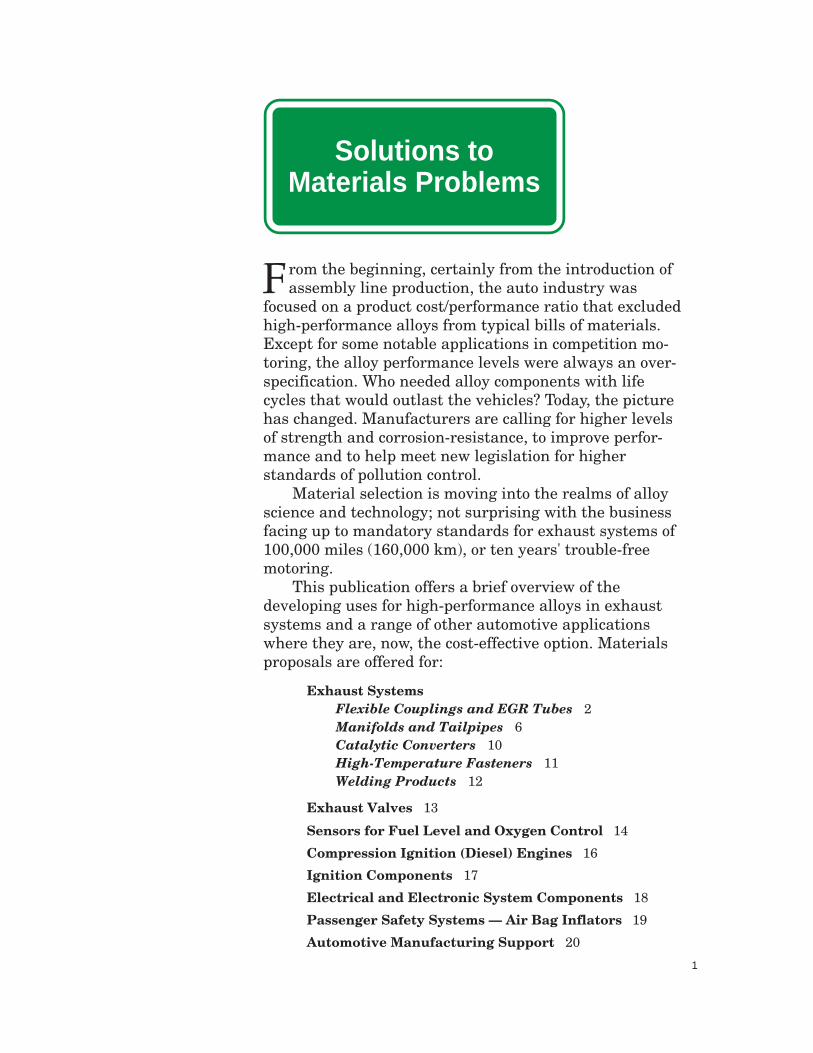
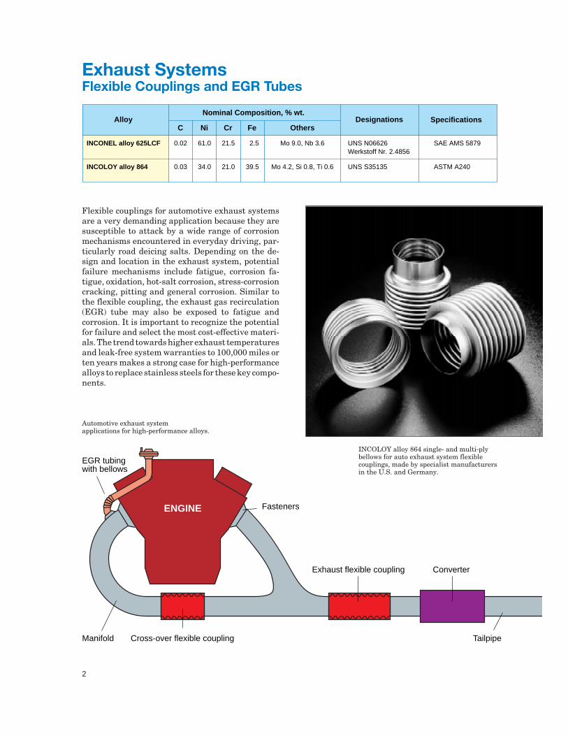
Flexible couplings for automotive exhaust systemsare a very demanding application because they aresusceptible to attack by a wide range of corrosionmechanisms encountered in everyday driving, par-ticularly road deicing salts. Depending on the de-sign and location in the exhaust system, potentialfailure mechanisms include fatigue, corrosion fa-tigue, oxidation, hot-salt corrosion, stress-corrosioncracking, pitting and general corrosion. Similar tothe flexible coupling, the exhaust gas recirculation(EGR) tube may also be exposed to fatigue andcorrosion. It is important to recognize the potentialfor failure and select the most cost-effective materi-als. The trend towards higher exhaust temperaturesand leak-free system warranties to 100,000 miles orten years makes a strong case for high-performancealloys to replace stainless steels for these key compo-nents.
Exhaust SystemsFlexible Couplings and EGR Tubes
INCOLOY alloy 864 single- and multi-plybellows for auto exhaust system flexiblecouplings, made by specialist manufacturersin the U.S. and Germany.
Automotive exhaust systemapplications for high-performance alloys.
Nominal Composition, % wt.Alloy
NiC Cr OthersDesignations Specifications
0.02
0.03
61.0
34.0
21.5
21.0
Mo 9.0, Nb 3.6
Mo 4.2, Si 0.8, Ti 0.6
UNS N06626 Werkstoff Nr. 2.4856
UNS S35135
SAE AMS 5879
ASTM A240
INCONEL alloy 625LCF
INCOLOY alloy 864
Fe
2.5
39.5
Fasteners
EGR tubingwith bellows
Manifold Cross-over flexible coupling
ConverterExhaust flexible coupling
Tailpipe
ENGINE
(Scan To Come)
3
Two of the Special Metals high-performancealloys demonstrate exceptional properties for flex-ible couplings: INCONEL alloy 625LCF andINCOLOY alloy 864. Adopted after many years ofsuccessful service in the aerospace industry,INCONEL alloy 625LCF is the premier material forflexible couplings used in the automotive industry,worldwide. INCOLOY alloy 864 was developed spe-cifically for the automotive industry as a cost-effec-tive alloy designed to provide better performancethan stainless steels for flexible coupling bellows
and other exhaust system applications. Both alloysare produced in thin strip suitable for bellows andEGR tubes, and both are readily formed and welded.
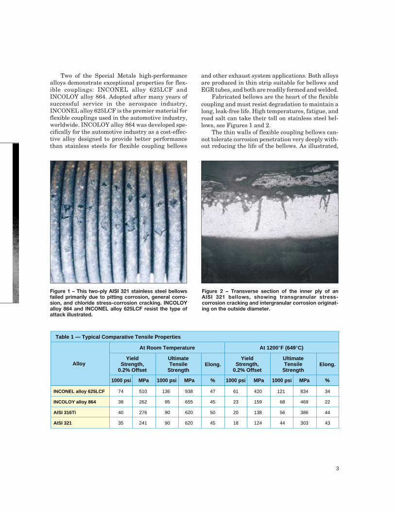
Fabricated bellows are the heart of the flexiblecoupling and must resist degradation to maintain along, leak-free life. High temperatures, fatigue, androad salt can take their toll on stainless steel bel-lows, see Figures 1 and 2.
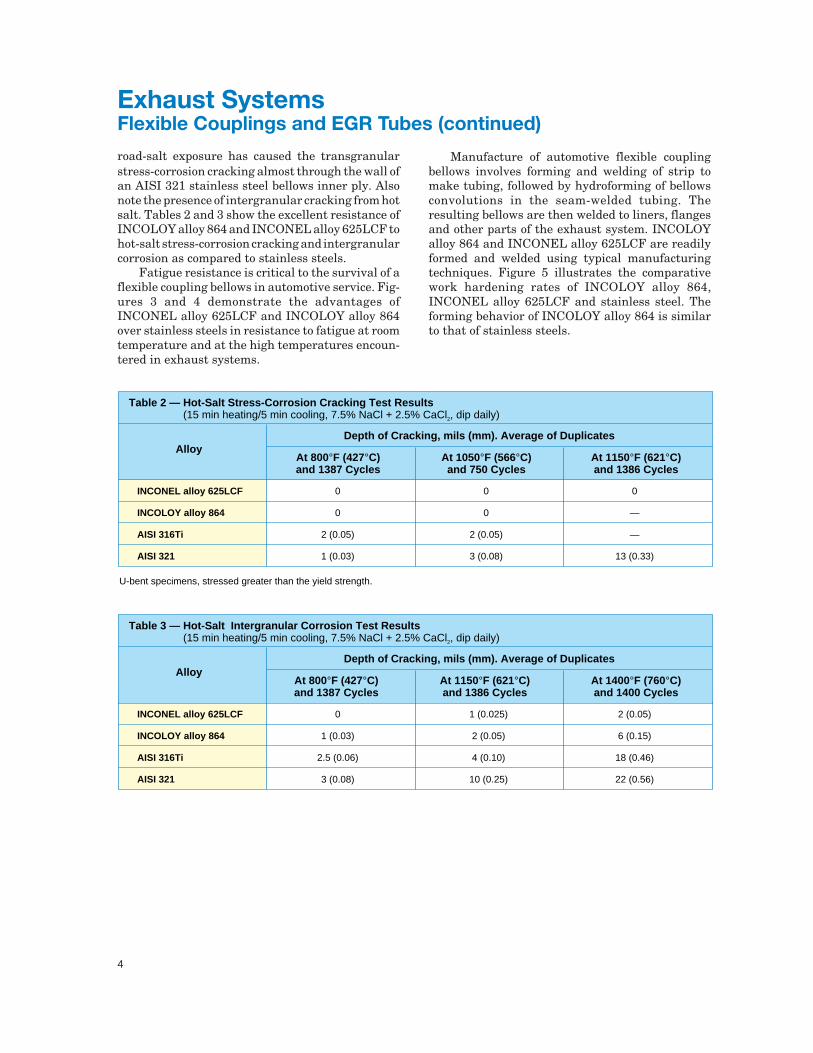
The thin walls of flexible coupling bellows can-not tolerate corrosion penetration very deeply with-out reducing the life of the bellows. As illustrated,
Figure 1 – This two-ply AISI 321 stainless steel bellowsfailed primarily due to pitting corrosion, general corro-sion, and chloride stress-corrosion cracking. INCOLOYalloy 864 and INCONEL alloy 625LCF resist the type ofattack illustrated.
Figure 2 – Transverse section of the inner ply of anAISI 321 bellows, showing transgranular stress-corrosion cracking and intergranular corrosion originat-ing on the outside diameter.
At Room Temperature At 1200°F (649°C)
Alloy
Table 1 — Typical Comparative Tensile Properties
YieldStrength,
0.2% Offset
UltimateTensile
StrengthElong.
%MPa1000 psiMPa1000 psi 1000 psi MPa 1000 psi MPa %
YieldStrength,
0.2% Offset
UltimateTensile
StrengthElong.
74
38
40
35
510
262
276
241
136
95
90
90
938
655
620
620
47
45
50
45
61
23
20
18
420
159
138
124
121
68
56
44
834
469
386
303
34
22
44
43
INCONEL alloy 625LCF
INCOLOY alloy 864
AISI 316Ti
AISI 321
4
road-salt exposure has caused the transgranularstress-corrosion cracking almost through the wall ofan AISI 321 stainless steel bellows inner ply. Alsonote the presence of intergranular cracking from hotsalt. Tables 2 and 3 show the excellent resistance ofINCOLOY alloy 864 and INCONEL alloy 625LCF tohot-salt stress-corrosion cracking and intergranularcorrosion as compared to stainless steels.
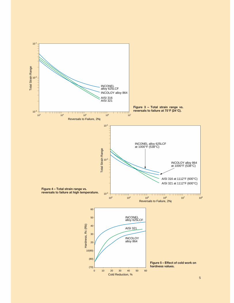
Fatigue resistance is critical to the survival of aflexible coupling bellows in automotive service. Fig-ures 3 and 4 demonstrate the advantages ofINCONEL alloy 625LCF and INCOLOY alloy 864over stainless steels in resistance to fatigue at roomtemperature and at the high temperatures encoun-tered in exhaust systems.
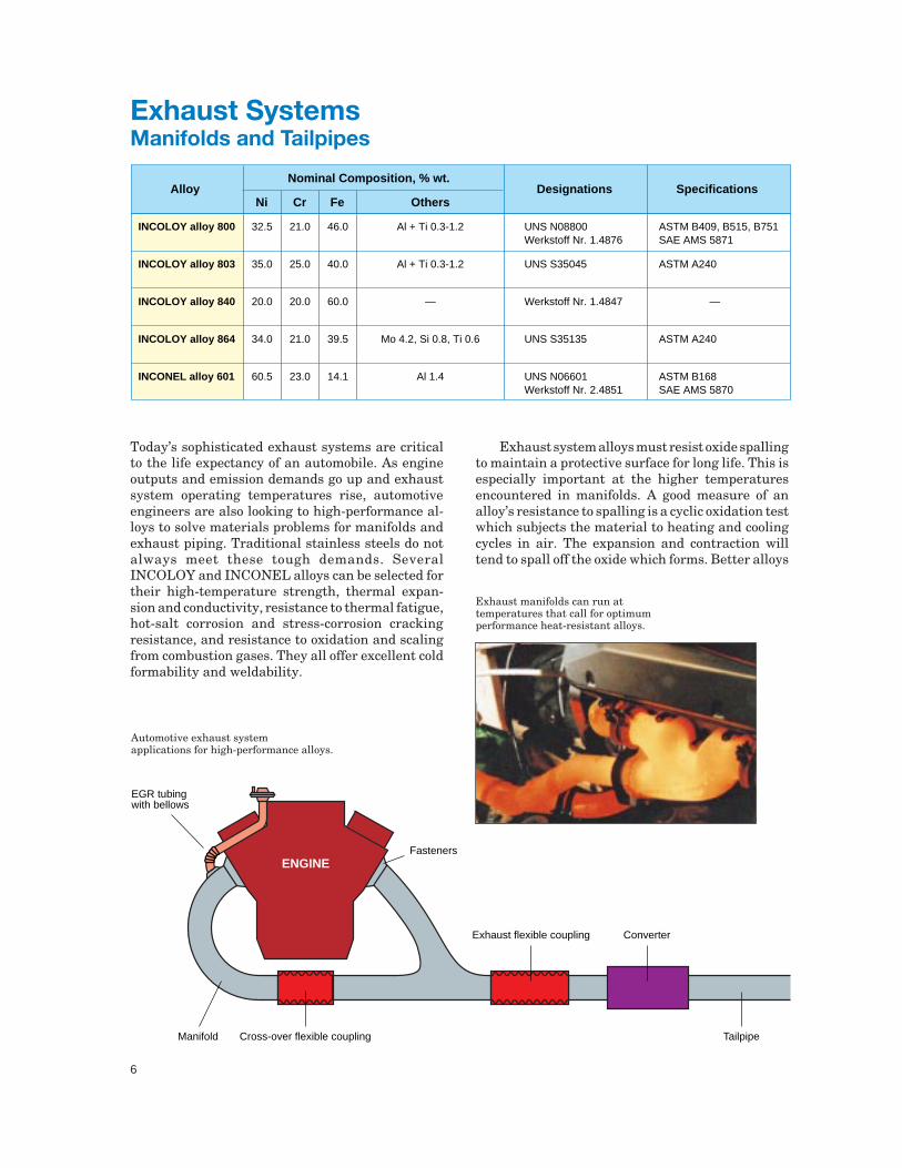
Manufacture of automotive flexible couplingbellows involves forming and welding of strip tomake tubing, followed by hydroforming of bellowsconvolutions in the seam-welded tubing. Theresulting bellows are then welded to liners, flangesand other parts of the exhaust system. INCOLOYalloy 864 and INCONEL alloy 625LCF are readilyformed and welded using typical manufacturingtechniques. Figure 5 illustrates the comparativework hardening rates of INCOLOY alloy 864,INCONEL alloy 625LCF and stainless steel. Theforming behavior of INCOLOY alloy 864 is similarto that of stainless steels.
Depth of Cracking, mils (mm). Average of DuplicatesAlloy
Table 2 — Hot-Salt Stress-Corrosion Cracking Test Results (15 min heating/5 min cooling, 7.5% NaCl + 2.5% CaCl2, dip daily)
At 800°F (427°C)and 1387 Cycles
At 1050°F (566°C)and 750 Cycles
At 1150°F (621°C)and 1386 Cycles
0
0
2 (0.05)
1 (0.03)
0
0
2 (0.05)
3 (0.08)
0
—
—
13 (0.33)
INCONEL alloy 625LCF
INCOLOY alloy 864
AISI 316Ti
AISI 321
U-bent specimens, stressed greater than the yield strength.
Depth of Cracking, mils (mm). Average of DuplicatesAlloy
Table 3 — Hot-Salt Intergranular Corrosion Test Results (15 min heating/5 min cooling, 7.5% NaCl + 2.5% CaCl2, dip daily)
At 800°F (427°C)and 1387 Cycles
At 1150°F (621°C)and 1386 Cycles
At 1400°F (760°C)and 1400 Cycles
0
1 (0.03)
2.5 (0.06)
3 (0.08)
1 (0.025)
2 (0.05)
4 (0.10)
10 (0.25)
2 (0.05)
6 (0.15)
18 (0.46)
22 (0.56)
INCONEL alloy 625LCF
INCOLOY alloy 864
AISI 316Ti
AISI 321
Exhaust SystemsFlexible Couplings and EGR Tubes (continued)
5
Figure 4 – Total strain range vs.reversals to failure at high temperature.
Figure 3 – Total strain range vs.reversals to failure at 75°F (24°C).
Figure 5 – Effect of cold work onhardness values.
103 104 105 106 107
INCONEL alloy 625LCFINCOLOY alloy 864
AISI 316AISI 321
Reversals to Failure, 2Nf
10-1
10-2
10-3
Tot
al S
trai
n R
ange
103 104 105 106 108107
Reversals to Failure, 2Nf
10-1
10-2
10-3
Tot
al S
trai
n R
ange
INCONEL alloy 625LCF at 1000°F (538°C)
INCOLOY alloy 864 at 1000°F (538°C)
AISI 321 at 1112°F (600°C)
AISI 316 at 1112°F (600°C)
0 10 20 30 40 50 60
INCOLOY alloy 864
Cold Reduction, %
60
50
40
30
20
10(90)
(80)
(70)
Har
dnes
s, R
c (R
b)
INCONEL alloy 625LCF
AISI 321
5
6
Today’s sophisticated exhaust systems are criticalto the life expectancy of an automobile. As engineoutputs and emission demands go up and exhaustsystem operating temperatures rise, automotiveengineers are also looking to high-performance al-loys to solve materials problems for manifolds andexhaust piping. Traditional stainless steels do notalways meet these tough demands. SeveralINCOLOY and INCONEL alloys can be selected fortheir high-temperature strength, thermal expan-sion and conductivity, resistance to thermal fatigue,hot-salt corrosion and stress-corrosion crackingresistance, and resistance to oxidation and scalingfrom combustion gases. They all offer excellent coldformability and weldability.
Nominal Composition, % wt.Alloy
CrNi Fe OthersDesignations Specifications
32.5
35.0
20.0
34.0
60.5
21.0
25.0
20.0
21.0
23.0
46.0
40.0
60.0
39.5
14.1
Al + Ti 0.3-1.2
Al + Ti 0.3-1.2
—
Mo 4.2, Si 0.8, Ti 0.6
Al 1.4
UNS N08800 Werkstoff Nr. 1.4876
UNS S35045
Werkstoff Nr. 1.4847
UNS S35135
UNS N06601Werkstoff Nr. 2.4851
ASTM B409, B515, B751SAE AMS 5871
ASTM A240
—
ASTM A240
ASTM B168SAE AMS 5870
INCOLOY alloy 800
INCOLOY alloy 803
INCOLOY alloy 840
INCOLOY alloy 864
INCONEL alloy 601
Exhaust system alloys must resist oxide spallingto maintain a protective surface for long life. This isespecially important at the higher temperaturesencountered in manifolds. A good measure of analloy’s resistance to spalling is a cyclic oxidation testwhich subjects the material to heating and coolingcycles in air. The expansion and contraction willtend to spall off the oxide which forms. Better alloys
Automotive exhaust systemapplications for high-performance alloys.
Exhaust SystemsManifolds and Tailpipes
Exhaust manifolds can run attemperatures that call for optimumperformance heat-resistant alloys.
Fasteners
EGR tubingwith bellows
Manifold Cross-over flexible coupling
ConverterExhaust flexible coupling
Tailpipe
ENGINE
7
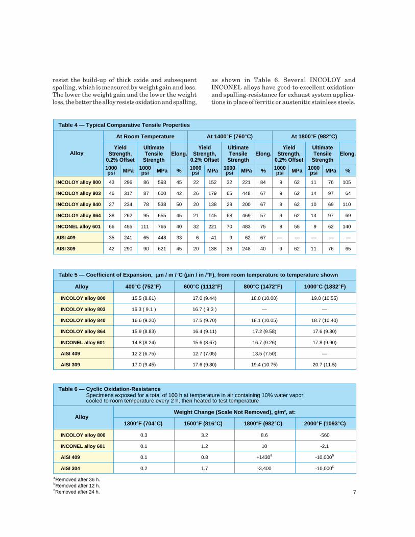
resist the build-up of thick oxide and subsequentspalling, which is measured by weight gain and loss.The lower the weight gain and the lower the weightloss, the better the alloy resists oxidation and spalling,
as shown in Table 6. Several INCOLOY andINCONEL alloys have good-to-excellent oxidation-and spalling-resistance for exhaust system applica-tions in place of ferritic or austenitic stainless steels.
At Room Temperature
Alloy
Table 4 — Typical Comparative Tensile Properties
YieldStrength,
0.2% Offset
UltimateTensile
StrengthElong.
%MPa1000 psi MPa1000
psi
43
46
27
38
66
35
42
296
317
234
262
455
241
290
86
87
78
95
111
65
90
593
600
538
655
765
448
621
45
42
50
45
40
33
45
INCOLOY alloy 800
INCOLOY alloy 803
INCOLOY alloy 840
INCOLOY alloy 864
INCONEL alloy 601
AISI 409
AISI 309
At 1400°F (760°C)
YieldStrength,
0.2% Offset
UltimateTensile
StrengthElong.
%MPa1000 psi MPa1000
psi
22
26
20
21
32
6
20
152
179
138
145
221
41
138
32
65
29
68
70
9
36
221
448
200
469
483
62
248
84
67
67
57
75
67
40
At 1800°F (982°C)
YieldStrength,
0.2% Offset
UltimateTensile
StrengthElong.
%MPa1000 psi MPa1000
psi
9
9
9
9
8
—
9
62
62
62
62
55
—
62
11
14
10
14
9
—
11
76
97
69
97
62
—
76
105
64
110
69
140
—
65
Table 5 — Coefficient of Expansion, µm / m /°C (µin / in /°F), from room temperature to temperature shown
400°C (752°F)Alloy
15.5 (8.61)
16.3 ( 9.1 )
16.6 (9.20)
15.9 (8.83)
14.8 (8.24)
12.2 (6.75)
17.0 (9.45)
600°C (1112°F)
17.0 (9.44)
16.7 ( 9.3 )
17.5 (9.70)
16.4 (9.11)
15.6 (8.67)
12.7 (7.05)
17.6 (9.80)
800°C (1472°F)
18.0 (10.00)
—
18.1 (10.05)
17.2 (9.58)
16.7 (9.26)
13.5 (7.50)
19.4 (10.75)
1000°C (1832°F)
19.0 (10.55)
—
18.7 (10.40)
17.6 (9.80)
17.8 (9.90)
—
20.7 (11.5)
INCOLOY alloy 800
INCOLOY alloy 803
INCOLOY alloy 840
INCOLOY alloy 864
INCONEL alloy 601
AISI 409
AISI 309
Table 6 — Cyclic Oxidation-ResistanceSpecimens exposed for a total of 100 h at temperature in air containing 10% water vapor, cooled to room temperature every 2 h, then heated to test temperature
1300°F (704°C)
Weight Change (Scale Not Removed), g/m2, at:Alloy
0.3
0.1
0.1
0.2
1500°F (816°C)
3.2
1.2
0.8
1.7
1800°F (982°C)
8.6
10
+1430a
-3,400
2000°F (1093°C)
-560
-2.1
-10,000b
-10,000c
INCOLOY alloy 800
INCONEL alloy 601
AISI 409
AISI 304
aRemoved after 36 h.bRemoved after 12 h.cRemoved after 24 h.
8
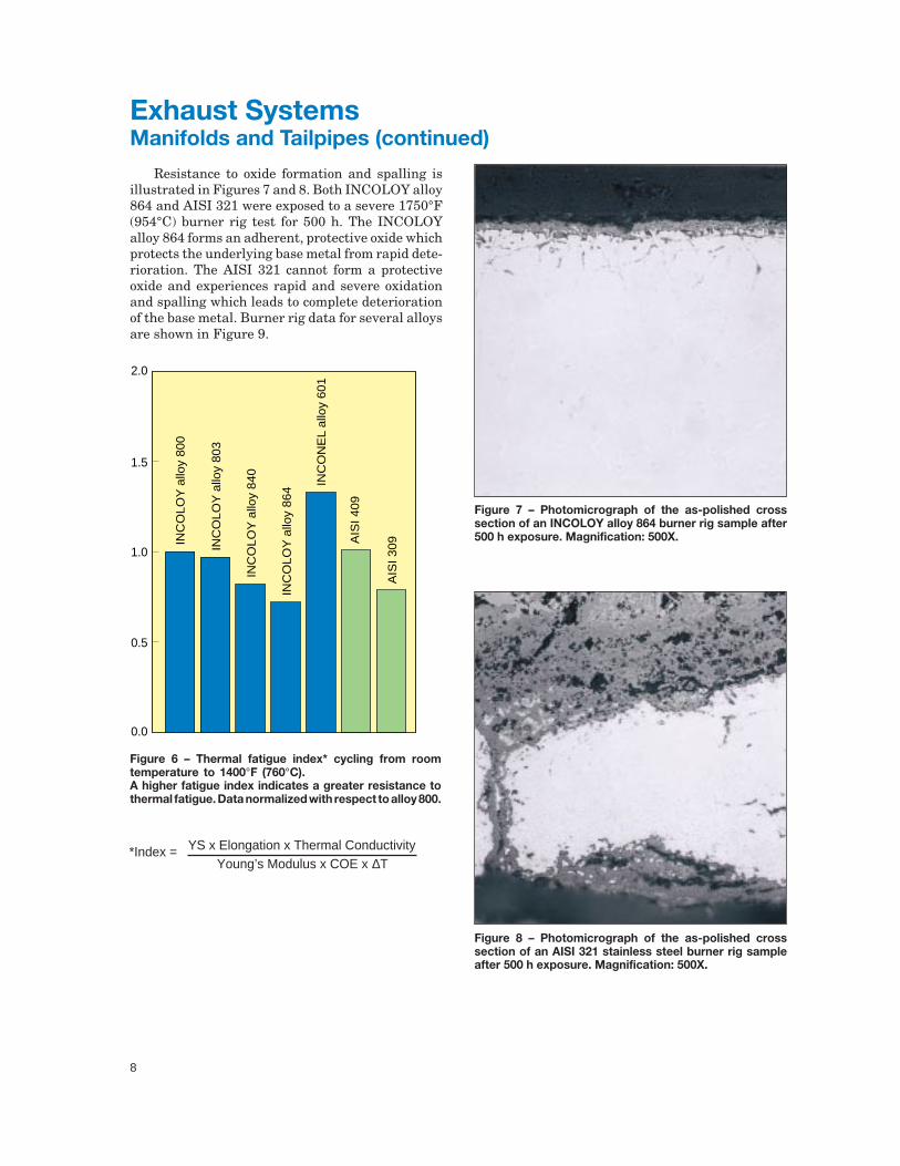
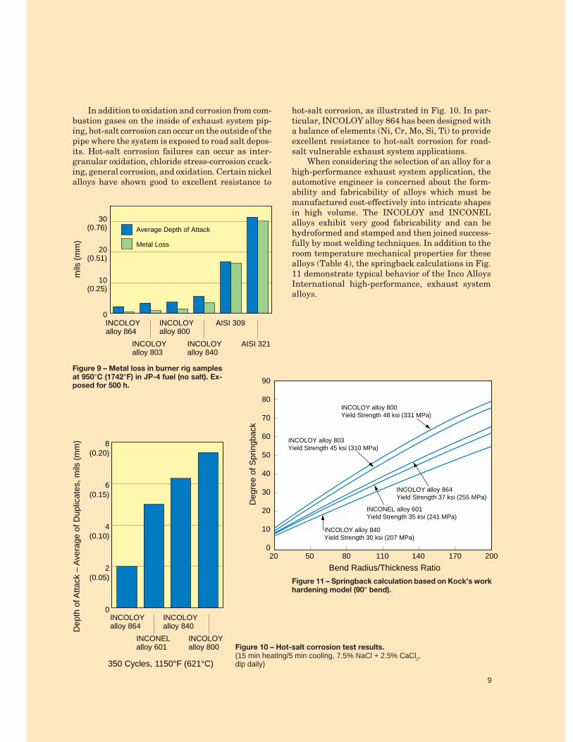
Resistance to oxide formation and spalling isillustrated in Figures 7 and 8. Both INCOLOY alloy864 and AISI 321 were exposed to a severe 1750°F(954°C) burner rig test for 500 h. The INCOLOYalloy 864 forms an adherent, protective oxide whichprotects the underlying base metal from rapid dete-rioration. The AISI 321 cannot form a protectiveoxide and experiences rapid and severe oxidationand spalling which leads to complete deteriorationof the base metal. Burner rig data for several alloysare shown in Figure 9.
Exhaust SystemsManifolds and Tailpipes (continued)
Figure 6 – Thermal fatigue index* cycling from roomtemperature to 1400°F (760°C).A higher fatigue index indicates a greater resistance tothermal fatigue. Data normalized with respect to alloy 800.
Figure 7 – Photomicrograph of the as-polished crosssection of an INCOLOY alloy 864 burner rig sample after500 h exposure. Magnification: 500X.
Figure 8 – Photomicrograph of the as-polished crosssection of an AISI 321 stainless steel burner rig sampleafter 500 h exposure. Magnification: 500X.
0.0
0.5
1.0
1.5
2.0
INC
OLO
Y a
lloy
800
INC
OLO
Y a
lloy
803
INC
OLO
Y a
lloy
864
AIS
I 409
INC
OLO
Y a
lloy
840
INC
ON
EL
allo
y 60
1
AIS
I 309
*Index = YS x Elongation x Thermal Conductivity Young’s Modulus x COE x ∆T
9
In addition to oxidation and corrosion from com-bustion gases on the inside of exhaust system pip-ing, hot-salt corrosion can occur on the outside of thepipe where the system is exposed to road salt depos-its. Hot-salt corrosion failures can occur as inter-granular oxidation, chloride stress-corrosion crack-ing, general corrosion, and oxidation. Certain nickelalloys have shown good to excellent resistance to
hot-salt corrosion, as illustrated in Fig. 10. In par-ticular, INCOLOY alloy 864 has been designed witha balance of elements (Ni, Cr, Mo, Si, Ti) to provideexcellent resistance to hot-salt corrosion for road-salt vulnerable exhaust system applications.
When considering the selection of an alloy for ahigh-performance exhaust system application, theautomotive engineer is concerned about the form-ability and fabricability of alloys which must bemanufactured cost-effectively into intricate shapesin high volume. The INCOLOY and INCONELalloys exhibit very good fabricability and can behydroformed and stamped and then joined success-fully by most welding techniques. In addition to theroom temperature mechanical properties for thesealloys (Table 4), the springback calculations in Fig.11 demonstrate typical behavior of the Inco AlloysInternational high-performance, exhaust systemalloys.
Figure 9 – Metal loss in burner rig samplesat 950°C (1742°F) in JP-4 fuel (no salt). Ex-posed for 500 h.
Figure 10 – Hot-salt corrosion test results.(15 min heating/5 min cooling, 7.5% NaCl + 2.5% CaCl2,dip daily)
Figure 11 – Springback calculation based on Kock’s workhardening model (90° bend).
9
0
10(0.25)
20(0.51)
30(0.76)
mils
(m
m)
INCOLOYalloy 864
INCOLOYalloy 803
INCOLOYalloy 840
INCOLOYalloy 800
AISI 309
AISI 321
Average Depth of Attack
Metal Loss
20
90
80
70
60
50
40
30
20
10
050 80 110 140 170 200
Deg
ree
of S
prin
gbac
k
Bend Radius/Thickness Ratio
INCONEL alloy 601Yield Strength 35 ksi (241 MPa)
INCOLOY alloy 800Yield Strength 48 ksi (331 MPa)
INCOLOY alloy 803Yield Strength 45 ksi (310 MPa)
INCOLOY alloy 840Yield Strength 30 ksi (207 MPa)
INCOLOY alloy 864Yield Strength 37 ksi (255 MPa)
0
2(0.05)
4(0.10)
6(0.15)
8(0.20)
Dep
th o
f Atta
ck –
Ave
rage
of D
uplic
ates
, mils
(m
m)
INCOLOYalloy 864
INCONELalloy 601
INCOLOYalloy 800
INCOLOYalloy 840
350 Cycles, 1150°F (621°C)
10
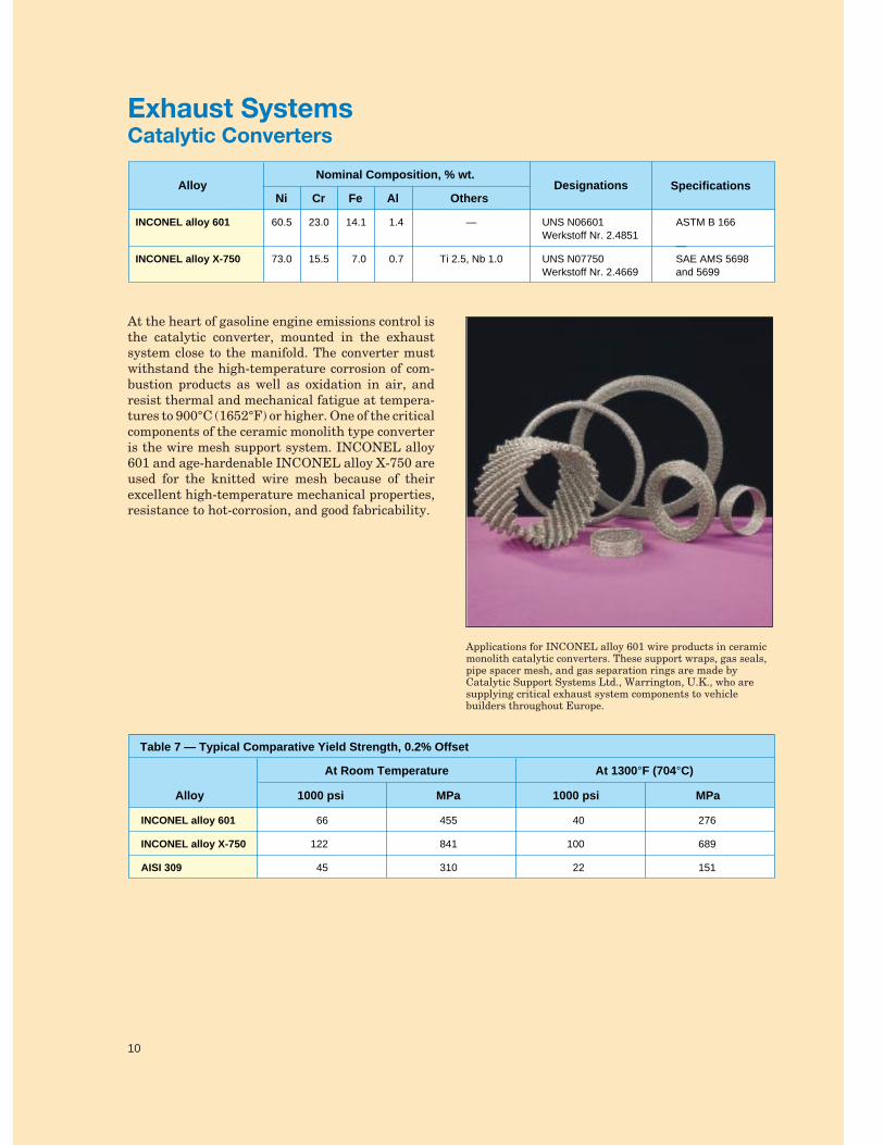
At the heart of gasoline engine emissions control isthe catalytic converter, mounted in the exhaustsystem close to the manifold. The converter mustwithstand the high-temperature corrosion of com-bustion products as well as oxidation in air, andresist thermal and mechanical fatigue at tempera-tures to 900°C (1652°F) or higher. One of the criticalcomponents of the ceramic monolith type converteris the wire mesh support system. INCONEL alloy601 and age-hardenable INCONEL alloy X-750 areused for the knitted wire mesh because of theirexcellent high-temperature mechanical properties,resistance to hot-corrosion, and good fabricability.
Exhaust SystemsCatalytic Converters
Nominal Composition, % wt.Alloy
CrNi Fe OthersDesignations Specifications
60.5
73.0
23.0
15.5
14.1
7.0
—
Ti 2.5, Nb 1.0
UNS N06601 Werkstoff Nr. 2.4851
UNS N07750Werkstoff Nr. 2.4669
ASTM B 166
—SAE AMS 5698and 5699
INCONEL alloy 601
INCONEL alloy X-750
Al
1.4
0.7
Applications for INCONEL alloy 601 wire products in ceramicmonolith catalytic converters. These support wraps, gas seals,pipe spacer mesh, and gas separation rings are made byCatalytic Support Systems Ltd., Warrington, U.K., who aresupplying critical exhaust system components to vehiclebuilders throughout Europe.
Table 7 — Typical Comparative Yield Strength, 0.2% Offset
1000 psi
At Room Temperature At 1300°F (704°C)
Alloy
66
122
45
MPa
455
841
310
1000 psi
40
100
22
MPa
276
689
151
INCONEL alloy 601
INCONEL alloy X-750
AISI 309
10
11
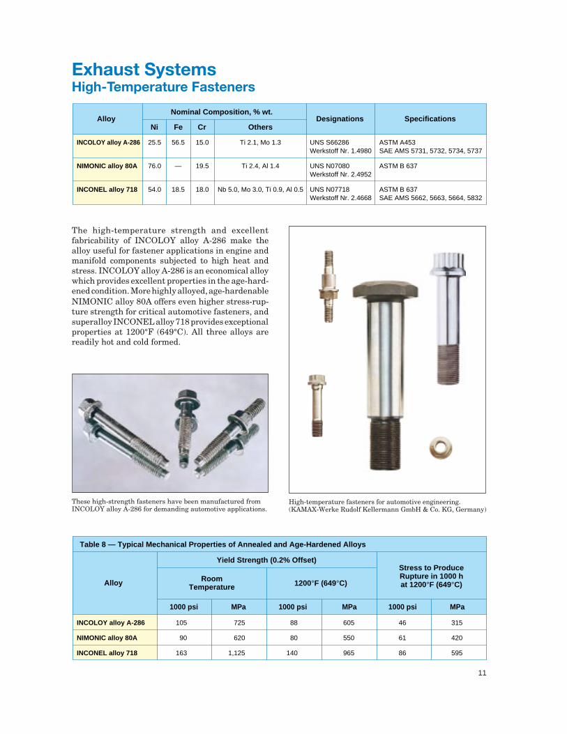
The high-temperature strength and excellentfabricability of INCOLOY alloy A-286 make thealloy useful for fastener applications in engine andmanifold components subjected to high heat andstress. INCOLOY alloy A-286 is an economical alloywhich provides excellent properties in the age-hard-ened condition. More highly alloyed, age-hardenableNIMONIC alloy 80A offers even higher stress-rup-ture strength for critical automotive fasteners, andsuperalloy INCONEL alloy 718 provides exceptionalproperties at 1200°F (649°C). All three alloys arereadily hot and cold formed.
Exhaust SystemsHigh-Temperature Fasteners
High-temperature fasteners for automotive engineering.(KAMAX-Werke Rudolf Kellermann GmbH & Co. KG, Germany)
These high-strength fasteners have been manufactured fromINCOLOY alloy A-286 for demanding automotive applications.
Nominal Composition, % wt.Alloy
FeNi Cr OthersDesignations Specifications
25.5
76.0
54.0
56.5
—
18.5
15.0
19.5
18.0
Ti 2.1, Mo 1.3
Ti 2.4, Al 1.4
Nb 5.0, Mo 3.0, Ti 0.9, Al 0.5
UNS S66286 Werkstoff Nr. 1.4980
UNS N07080 Werkstoff Nr. 2.4952
UNS N07718 Werkstoff Nr. 2.4668
ASTM A453SAE AMS 5731, 5732, 5734, 5737
ASTM B 637
ASTM B 637SAE AMS 5662, 5663, 5664, 5832
INCOLOY alloy A-286
NIMONIC alloy 80A
INCONEL alloy 718
Yield Strength (0.2% Offset)Stress to Produce Rupture in 1000 h at 1200°F (649°C)Alloy
Table 8 — Typical Mechanical Properties of Annealed and Age-Hardened Alloys
Room Temperature 1200°F (649°C)
MPa1000 psiMPa1000 psi 1000 psi MPa
105
90
163
725
620
1,125
88
80
140
605
550
965
46
61
86
315
420
595
INCOLOY alloy A-286
NIMONIC alloy 80A
INCONEL alloy 718
12
The manufacture and assembly of automotive ex-haust systems require welded combinations of dif-ferent cast and wrought alloy compositions andstructures.
NI-ROD 44 filler metal and NI-ROD 44HT arestrategic compositions specially formulated forwelding oxidation- and carburization-resistantductile iron castings. They have excellent weld-ability, strength, and good coefficient of thermalexpansion (CTE) matches with both ductile ironsand the AISI 400 stainless steels.
NI-ROD 44 filler metal was one of the firstwelding products used for joining ductile iron inautomotive applications. As operating temperaturesrose, Special Metals recognized the need for a prod-uct with greater oxidation-resistance and metallurgi-cal stability against graphitization. NI-ROD 44HT(“HT” for high temperature), a developmental alloy,was patented in 1995 for this precise purpose.
Exhaust SystemsWelding Products
Nominal Composition, % wt.Alloy
FeNi Mn OthersDesignations
44.0
44.0
45.0
36.0
11.0
11.0
C 0.3
Cr 8.0, Nb 1.0
UNS N02216
—
NI-ROD 44 filler metal
NI-ROD 44HT
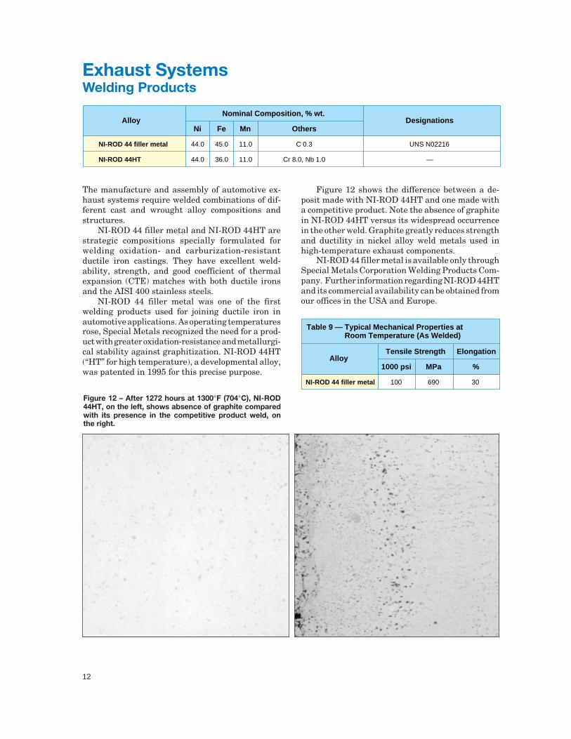
Figure 12 shows the difference between a de-posit made with NI-ROD 44HT and one made witha competitive product. Note the absence of graphitein NI-ROD 44HT versus its widespread occurrencein the other weld. Graphite greatly reduces strengthand ductility in nickel alloy weld metals used inhigh-temperature exhaust components.
NI-ROD 44 filler metal is available only throughSpecial Metals Corporation Welding Products Com-pany. Further information regarding NI-ROD 44HTand its commercial availability can be obtained fromour offices in the USA and Europe.
Tensile Strength
Table 9 — Typical Mechanical Properties at Room Temperature (As Welded)
ElongationAlloy
MPa1000 psi %
100 690 30NI-ROD 44 filler metal
Figure 12 – After 1272 hours at 1300°F (704°C), NI-ROD44HT, on the left, shows absence of graphite comparedwith its presence in the competitive product weld, onthe right.
13
High-performance diesel and gasoline engines, op-erating at high temperatures and high exhaust gaspressures, require exhaust valve alloys with excel-lent hot strength and hardness, and good hot corro-sion- and wear-resistance. Under these conditions,traditional valve steels are inadequate and valve
Exhaust Valves
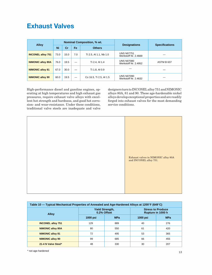
Exhaust valves in NIMONIC alloy 80Aand INCONEL alloy 751.
designers turn to INCONEL alloy 751 and NIMONICalloys 80A, 81 and 90. These age-hardenable nickelalloys develop exceptional properties and are readilyforged into exhaust valves for the most demandingservice conditions.
Nominal Composition, % wt.Alloy
CrNi Fe OthersDesignations Specifications
UNS N07751Werkstoff Nr. 2.4669
UNS N07080Werkstoff Nr. 2.4952
—
UNS N07090Werkstoff Nr. 2.4632
73.0
76.0
67.0
60.0
15.0
19.5
30.0
19.5
7.0
—
—
—
Ti 2.5, Al 1.1, Nb 1.0
Ti 2.4, Al 1.4
Ti 1.8, Al 0.9
Co 16.5, Ti 2.5, Al 1.5
—
ASTM B 637
—
—
INCONEL alloy 751
NIMONIC alloy 80A
NIMONIC alloy 81
NIMONIC alloy 90
Alloy
Table 10 — Typical Mechanical Properties of Annealed and Age-Hardened Alloys at 1200°F (649°C)
Yield Strength,0.2% Offset
Stress to Produce Rupture in 1000 h
MPa1000 psi 1000 psi MPa
129
80
72
99
48
889
550
495
685
330
40
61
53
66
30
276
420
365
455
207
INCONEL alloy 751
NIMONIC alloy 80A
NIMONIC alloy 81
NIMONIC alloy 90
21-4 N Valve Steel*
* not age-hardened
14
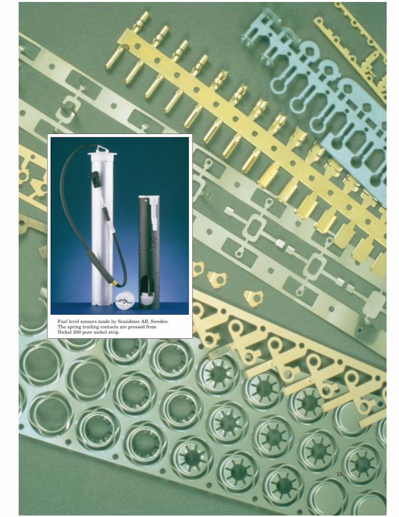
Commercially pure wrought nickel (Nickel 200) isused for spring trailing contacts in fuel sensors,selected for its resistance to corrosion, its springproperties, and its amenability to the high-pressureforming operation in which the contacts are pressedfrom strip.
Nominal Composition, % wt.Alloy
CrNi FeDesignations Specifications
99.6
60.5
—
23.0
—
14.1
UNS N02200 Werkstoff Nr. 2.4060/66
UNS N06601Werkstoff Nr. 2.4851
ASTM B 162
ASTM B 168SAE AMS 5870
Nickel 200
INCONEL alloy 601
Al
—
1.4
Sensors for Fuel Level and Oxygen Control
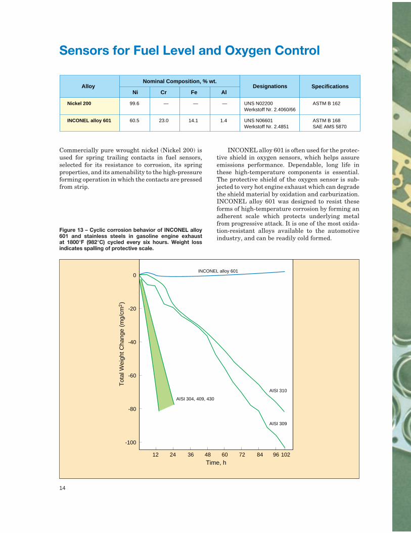
INCONEL alloy 601 is often used for the protec-tive shield in oxygen sensors, which helps assureemissions performance. Dependable, long life inthese high-temperature components is essential.The protective shield of the oxygen sensor is sub-jected to very hot engine exhaust which can degradethe shield material by oxidation and carburization.INCONEL alloy 601 was designed to resist theseforms of high-temperature corrosion by forming anadherent scale which protects underlying metalfrom progressive attack. It is one of the most oxida-tion-resistant alloys available to the automotiveindustry, and can be readily cold formed.
Figure 13 – Cyclic corrosion behavior of INCONEL alloy601 and stainless steels in gasoline engine exhaustat 1800°F (982°C) cycled every six hours. Weight lossindicates spalling of protective scale.
12 24 36 48 60 72 84 96 102
0
-20
-40
-60
-80
-100
Tot
al W
eigh
t Cha
nge
(mg/
cm2)
Time, h
INCONEL alloy 601
AISI 304, 409, 430
AISI 310
AISI 309
15
Fuel level sensors made by Scandmec AB, Sweden.The spring trailing contacts are pressed fromNickel 200 pure nickel strip.
15
16
Nominal Composition, % wt.Alloy
FeNi Cr OthersDesignations Specifications
—
60.5
74.0
14.1
20.0
23.0
Ti 0.5, Y2O3 0.5
—
UNS S67956
UNS N06601Werkstoff Nr. 2.4851
—
ASTM B 166SAE AMS 5870
INCOLOY alloy MA956
INCONEL alloy 601
Al
4.5
1.4
Compression Ignition (Diesel) Engines
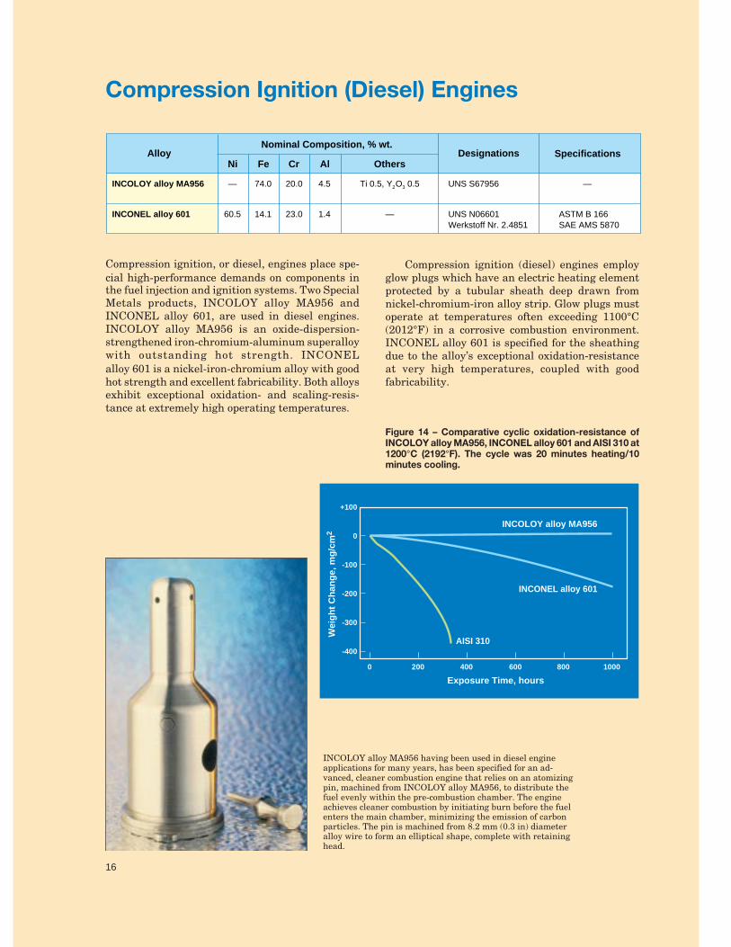
Compression ignition, or diesel, engines place spe-cial high-performance demands on components inthe fuel injection and ignition systems. Two SpecialMetals products, INCOLOY alloy MA956 andINCONEL alloy 601, are used in diesel engines.INCOLOY alloy MA956 is an oxide-dispersion-strengthened iron-chromium-aluminum superalloywith outstanding hot strength. INCONELalloy 601 is a nickel-iron-chromium alloy with goodhot strength and excellent fabricability. Both alloysexhibit exceptional oxidation- and scaling-resis-tance at extremely high operating temperatures.
Compression ignition (diesel) engines employglow plugs which have an electric heating elementprotected by a tubular sheath deep drawn fromnickel-chromium-iron alloy strip. Glow plugs mustoperate at temperatures often exceeding 1100°C(2012°F) in a corrosive combustion environment.INCONEL alloy 601 is specified for the sheathingdue to the alloy’s exceptional oxidation-resistanceat very high temperatures, coupled with goodfabricability.
INCOLOY alloy MA956 having been used in diesel engineapplications for many years, has been specified for an ad-vanced, cleaner combustion engine that relies on an atomizingpin, machined from INCOLOY alloy MA956, to distribute thefuel evenly within the pre-combustion chamber. The engineachieves cleaner combustion by initiating burn before the fuelenters the main chamber, minimizing the emission of carbonparticles. The pin is machined from 8.2 mm (0.3 in) diameteralloy wire to form an elliptical shape, complete with retaininghead.
Figure 14 – Comparative cyclic oxidation-resistance ofINCOLOY alloy MA956, INCONEL alloy 601 and AISI 310 at1200°C (2192°F). The cycle was 20 minutes heating/10minutes cooling.
16
0 200 400 600 800 1000
Exposure Time, hours
+100
0
-100
-200
-300
-400
Wei
gh
t C
han
ge,
mg
/cm
2
INCOLOY alloy MA956
INCONEL alloy 601
AISI 310
17
Nominal Composition, % wt.
Automotive Spark Plug Alloys*
AlloyCrNi Mn Others
Designations Specifications
94.8
96.2
76.8
1.8
1.6
14.6
1.95
1.6
0.3
Ti 0.3, Zr 0.15
—
Fe 7.6, Al 0.065,Ti 0.061, Zr 0.01
—
—
UNS N06600Werkstoff Nr. 2.4816
—
—
ASTM B 166SAE AMS 5687
Nickel 240
Nickel 243
INCONEL alloy 600SP
Si
0.45
0.55
0.4
C
0.05
0.05
0.02
* Other compositions available on request.
Ignition Components
The unique characteristics of nickel alloys makethem ideal for several applications in automotiveengine ignition systems. There are several carefullycrafted compositions utilized in spark plugs for gaso-line engines. These provide a balance of properties,including thermal conductivity, electrical conduc-tivity, and resistance to spark erosion and corrosion.A conventional spark plug design may have a roundcenter electrode of solid nickel alloy or a nickel-chromium outer sheath and a copper alloy innercore. The outer sheath must resist the corrosivegases from combustion, and the inner core musthave good thermal conductivity to dissipate heat.The rectangular/rhomboidal ground electrode typi-cally is also a nickel-chromium alloy. Operatingtemperatures range from 400°C (752°F) to 900°C(1652°F). Spark plug alloys must perform well formany years in long-life designs of higher outputengines.
A typical spark plug design where the round center electrodewould have a nickel alloy inner core or a nickel-chromiumouter layer and a copper alloy inner core, and the rectangular/rhomboidal section ground electrode is in nickel-chromiumalloy. Operating temperatures are typically 400 to 900°C (752to 1652°F).

18
Nominal Composition, % wt.Alloy
CuNi Mn OthersDesignations Specifications
99.6
95.0
65.1
52.5
45.0
—
—
32.0
47.0
55.0
—
4.75
1.1
—
—
Mg 0.04
—
Fe 1.6
—
—
UNS N02205 Werkstoff Nr. 2.4061
UNS N02211
UNS N04400 Werkstoff Nr. 2.4360
UNS N04404
Werkstoff Nr. 2.0842
ASTM F1 and F3SAE AMS 5555
ASTM F290
ASTM B 127SAE AMS 4544, 4731
ASTM F96
ASTM B 267
Nickel 205
Nickel 211
MONEL alloy 400
MONEL alloy 404
FERRY alloy
Table 11 — Thermal and Electrical Properties at Room Temperature
Btu•in/ft2•h•°F
Thermal Conductivity Electrical ResistivityAlloy
520
306
151
146
155
W/m•°C
75.0
44.2
21.8
21.1
22.4
ohm•circ mil/ft
57
102
329
300
295
µ Ω • m
0.095
0.170
0.547
0.500
0.490
Nickel 205
Nickel 211
MONEL alloy 400
MONEL alloy 404
FERRY alloy
Electrical and Electronic System Components
Several pure nickel grades and other nickel-copperand copper-nickel alloys are used in automotiveelectrical and electronic components because of theirelectrical and thermal properties. Examples of suchapplications include terminals, lead wires, connec-tors, diodes, resistors, thermostats, magnetostric-tive devices and housings.
This outline sketch gives some indication of the locations in atypical automobile where nickel alloys could be used forelectrical components.
FERRY copper-nickel alloy strip is usedfor the contacts of bi-metal, snap actionswitches from thermostats, circuitbreakers, sensors and motor protectorsto programmable electronic controllers.
SUNROOF MOTORREAR WINDSHIELDWIPER MOTOR
ANTENNALIFT MOTOR
ELECTRIC DOORLOCK MOTOR
SEAT ADJUSTMOTOR
WINDOW LIFTMOTOR REAR VIEW
MIRROR ADJUSTMOTOR
HEADLIGHTWIPER MOTOR
ELECTRICCOOLING FAN
HEADLIGHTWASHER PUMPMOTOR
WINDSHIELDWASHER PUMPMOTOR
WIPERMOTOR
HEATED REARVIEW MIRROR
INTERIOR HEATERand AIR CONDITIONER
COLD STARTAID
HEATED SEAT
CHOKEWARNING
OIL OVERHEATWARNING RESETTABLE
THERMAL FUSE
WIRING HARNESSPROTECTION
FUEL FILLERSOLENOID
TIRE PRESSURE andTEMPERATURE MONITOR

19
Nominal Composition, % wt.Alloy
CrNi Fe OthersDesignations Specifications
76.0
61.0
15.0
21.5
8.0
2.5
—
Mo 9.0, Nb 3.6
UNS N06600 Werkstoff Nr. 2.4816
UNS N06626 Werkstoff Nr. 2.4856
ASTM B 168SAE AMS 5540
ASTM B 443SAE AMS 5599 and 5879
INCONEL alloy 600
INCONEL alloy 625LCF
Table 12 — Typical Mechanical Properties of Cold-Rolled, Annealed Strip at Room Temperature
1000 psi
Tensile Strength Yield Strength ElongationAlloy
97
137
MPa
669
945
1000 psi
46
70
MPa
317
483
%
39
47
INCONEL alloy 600
INCONEL alloy 625LCF
Passenger Safety Systems – Air Bag Inflators
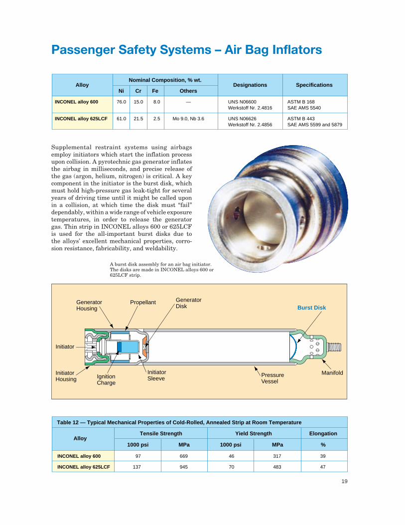
Supplemental restraint systems using airbagsemploy initiators which start the inflation processupon collision. A pyrotechnic gas generator inflatesthe airbag in milliseconds, and precise release ofthe gas (argon, helium, nitrogen) is critical. A keycomponent in the initiator is the burst disk, whichmust hold high-pressure gas leak-tight for severalyears of driving time until it might be called uponin a collision, at which time the disk must “fail”dependably, within a wide range of vehicle exposuretemperatures, in order to release the generatorgas. Thin strip in INCONEL alloys 600 or 625LCFis used for the all-important burst disks due tothe alloys’ excellent mechanical properties, corro-sion resistance, fabricability, and weldability.
A burst disk assembly for an air bag initiator.The disks are made in INCONEL alloys 600 or625LCF strip.
GeneratorHousing
Propellant
Initiator
InitiatorHousing Ignition
Charge
InitiatorSleeve
Pressure Vessel
Manifold
GeneratorDisk Burst Disk
20
Nominal Composition, % wt.Alloy
CrNi Fe OthersDesignations Specifications
76.0
60.5
32.5
35.0
35.5
80.0
15.5
22.0
21.0
25.0
18.5
19.5
8.0
14.1
46.0
36.0
44.0
—
—
Al 1.4
C 0.08, Al + Ti 1.0
Al 0.6, Ti 0.6, Si 0.6,Mn 0.9, C 0.09
Si 1.2
—
UNS N06600 Werkstoff Nr. 2.4816
UNS N06601 Werkstoff Nr. 2.4851
UNS N08811 Werkstoff Nr. 1.4876
UNS S35045
UNS N08330 Werkstoff Nr. 1.4864
UNS N06075 Werkstoff Nr. 2.4951
ASTM B166, B167, B168SAE AMS 5540, 5665
ASTM B166, B167, B168SAE AMS 5715 and 5870
ASTM B407, B408, B409
ASTM A240
ASTM B512, B536SAE AMS 5592, 5716
BS HR203, HR504
INCONEL alloy 600
INCONEL alloy 601
INCOLOY alloy 800HT
INCOLOY alloy 803
INCOLOY alloy 330
NIMONIC alloy 75
Manufacturing Applications in the Automotive Industry
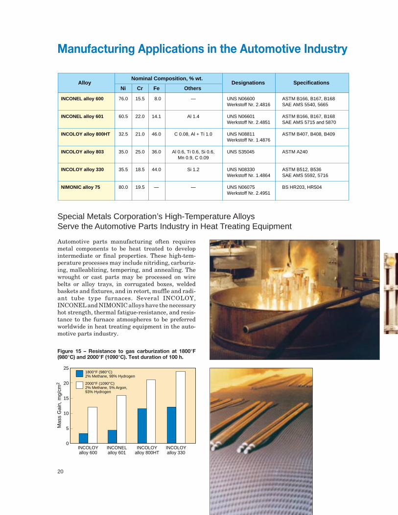
Automotive parts manufacturing often requiresmetal components to be heat treated to developintermediate or final properties. These high-tem-perature processes may include nitriding, carburiz-ing, malleablizing, tempering, and annealing. Thewrought or cast parts may be processed on wirebelts or alloy trays, in corrugated boxes, weldedbaskets and fixtures, and in retort, muffle and radi-ant tube type furnaces. Several INCOLOY,INCONEL and NIMONIC alloys have the necessaryhot strength, thermal fatigue-resistance, and resis-tance to the furnace atmospheres to be preferredworldwide in heat treating equipment in the auto-motive parts industry.
Special Metals Corporation’s High-Temperature AlloysServe the Automotive Parts Industry in Heat Treating Equipment
Figure 15 – Resistance to gas carburization at 1800°F(980°C) and 2000°F (1090°C). Test duration of 100 h.
INCOLOYalloy 600
INCONELalloy 601
INCOLOYalloy 800HT
INCOLOYalloy 330
25
20
15
10
5
0
Mas
s G
ain,
mg/
cm2
1800°F (980°C)2% Methane, 98% Hydrogen
2000°F (1090°C)2% Methane, 5% Argon, 93% Hydrogen
21
Alloy
Table 13 — Yield Strength, 0.2% Offset
MPa1000 psi 1000 psi MPa
35
35
34
45
39
42
241
241
234
310
269
290
9
18
17
18
17
17
62
124
117
124
117
117
INCONEL alloy 600
INCONEL alloy 601
INCOLOY alloy 800HT
INCOLOY alloy 803
INCOLOY alloy 330
NIMONIC alloy 75
70°F (20°C) 1600°F (871°C)
Figure 16 – 10,000-hour rupture strength of candidatematerials for thermal processing applications.
21
20
1086
4
2
10.80.6
0.4
0.2
0.1
1008060
40
20
1086
4
2
1
INCONEL alloy 601
INCOLOY alloy 800HT
NIMONICalloy 75
AISI 309
INCONEL alloy 600
AISI 310
INCOLOY alloy 330
1300(704)
750 800 850 900 950 100 1050
1400(760)
1500(816)
1600(871)
1700(927)
1800(982)
1900(1038)
2000(1093)
Temperature, °F (°C)
Temperature, °CS
tres
s, 1
000
psi
Str
ess,
MP
a