Embed Size (px)
Citation preview
Accurate Lambda Meter ALM-S Manual V1.4
ALM-S
Accurate Lambda Meter
Manual v1.4
Check before you power on ALM-S:
The oxygen sensor is installed in the right way (page 8); or if it's
left in the free air, make sure it's dry and it's not close to the
inflammable materials.
The ALM-S is correctly connected to DC power supply or 12V
battery; (page 10)
www.ecotrons.com Page 1 of 29
Accurate Lambda Meter ALM-S Manual V1.4
Revision History
Data Revision
Level Description
V 1.1 PRELIMINARY
Oct 2012 V1.2 1. Updated some pictures
2. Updated chapter 5.2.6:Lambda analog output
Oct 2012 V1.3 1. Re-numbered manual
2. Add analog output diagnosis capability description
Jan 2013 V1.4 Add Chapter 7: Frequently Asked Questions
www.ecotrons.com Page 2 of 29
Accurate Lambda Meter ALM-S Manual V1.4
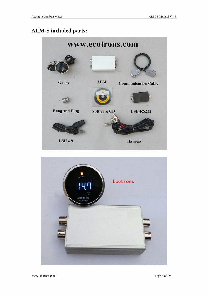
ALM-S included parts:
www.ecotrons.com Page 3 of 29
Accurate Lambda Meter ALM-S Manual V1.4
Table of Content
Chapter 1 ALM-S Product Overview................................................................................................5
Chapter 2 ALM-S technical specifications........................................................................................6
Chapter 3 Protect your oxygen sensor ..............................................................................................8
Chapter 4 ALM-S hardware connections ..........................................................................................9
4.1 ALM-S main connector pin-out ....................................................................................9
4.2 Connection overview ..................................................................................................10
Chapter 5 Software instructions ......................................................................................................12
5.1 Install Software ...........................................................................................................12
5.1.1 Setup......................................................................................................................12
5.1.2 Welcome Window .................................................................................................12
5.1.3 Change Directory ..................................................................................................12
5.1.4 Setup Successful....................................................................................................13
5.2 Using Software............................................................................................................13
5.2.1 Communication Port Selection..............................................................................14
5.2.2 Running the software ............................................................................................14
5.2.3 Graph Window ......................................................................................................15
5.2.4 Diagnostic Trouble Code.......................................................................................16
5.2.5 ALM-S GUI Parameters Settings..........................................................................16
5.2.6 Analog output diagnosis capability .......................................................................18
5.2.7 Real-Time Signals .................................................................................................19
5.2.8 Data logging and play-back...................................................................................19
Chapter 6 DTC table .......................................................................................................................22
Chapter 7 Frequently Asked Questions...........................................................................................23
7.1 ALM-GUI ANOUT set ...............................................................................................23
7.2 Program ALM with Flash GUI....................................................................................24
7.3 Calibration set .............................................................................................................26
7.4 How to calibration ECU readings of ALM analog output...........................................27
Chapter 8 Appendix: LSU4.9 vs LSU4.2........................................................................................29
www.ecotrons.com Page 4 of 29

Accurate Lambda Meter ALM-S Manual V1.4
Chapter 1 ALM-S Product Overview
ALM-S (Accurate Lambda Meter) is an air/fuel ratio (lambda) meter which uses Bosch LSU 4.9
wideband oxygen sensor and Bosch driver chip CJ125 to accurately measure the exhaust air/fuel
ratio (AFR) of variant combustion engines.
ALM-S is a smaller size version of our previous ALM . It has the same accuracy and fast response
characteristics like ALM, but much smaller size. The controller box has the size of 4"x2.6"x1", or
similar to a business card size. It has a primary 0-5v linear analog output which can be used as the
feedback control signal for an ECU. It also has an analog signal output to the 52mm digital LED
gauge. The gauge is optional, because some professional tuners already have a lot of gauges which
include AFR display as a part.
Further more, it has the new feature of CAN bus communication as optional. This is a more
advanced feature for professional engine controls where CAN bus is used widely and AFR signal
can be broadcasted on the CAN bus.
Our ALM uses more advanced LSU4.9 sensor instead of LSU4.2 which is still used by most other
wideband controllers. LSU4.9 is the new generation wideband sensor evolving from LSU4.2. It is
superior to LSU4.2 with the obvious proof: Bosch uses LSU4.9 across the board for their
wideband applications. (Appendix: LSU4.9 vs LSU4.2)
CJ125 is the driver chip specifically designed by Bosch for LSU 4.9/4.2 Sensors. Bosch's own
wideband controller, "Lambda Tonic", uses CJ125 driver chip. Actually Bosch uses this chip
wherever the LSU sensors are used. They are mated-pair by Bosch. Presumably LSU sensors work
the best with CJ125 chips.
Together, LSU 4.9 and CJ125 make our ALM a more accurate lambda meter in the automotive
aftermarket.
Besides air/fuel ratio measurement, ALM-S provides some supplemental functions which make
your measurement or tuning more convenient: linear analog output to your ECU; LED digital
display; engine RPM probe, data logging with a serial communication to a PC, etc.
www.ecotrons.com Page 5 of 29

Accurate Lambda Meter ALM-S Manual V1.4
Chapter 2 ALM-S technical specifications
Power supply
Input voltage range DC 9V~15 V (12V Typical)
Input current 90mA typical plus the heater current
Polarity protection Reverse polarity protected
Load Dump Clamp Maximum Voltage 33V
Sensors
Compatible LSU4.9 (LSU 4.2 capable but not recommended)
Number of Sensors One
Free air calibration Not required
Measurement
Lambda range λ = 0.65 ~ ∞(AFR: 9.56 to free air)
Lambda accuracy ±0.008 @ λ=1.00
±0.01 @ λ=0.80
±0.05 @ λ=1.70
Air/Fuel Ratio Fuel dependent (see lambda range and accuracy)
Heater
Control built-in PID control with CJ125
Current Typical 600mA; Max 1.3A
Heater return (H-) Separate wire from Ground
Response time
5ms sampling rate
Output
Lambda analog output 0~5V user programmable
Analog accuracy ±0.005V error with a 10-bit DAC chip
Analog type Reference ground to ECU
Narrow band O2 sensor simulated output
Input
RPM input Injection pick-up
Communications
advanced CAN bus communications (optional)
RS232 or USB (via a converter)
User-friendly PC software for data acquisitions and analysis
www.ecotrons.com Page 6 of 29
Accurate Lambda Meter ALM-S Manual V1.4
Display
52mm digital guage with numbers in the censor and bar-graph LEDs around
Low cost LED digital display (optional)
Main-Processor
CPU Freescale MC9S12P128 16-bit
Speed 32MHz
Memory 128k Flash, 6k Ram, 4k Data
Special features
On-Board-Diagnosis and error report
Self-learning of part-to-part variations, aging effect
Working with different types of fuels (gasoline, diesel, E85, etc)
General
Temperature range -30oC ~ 125oC
Dimensions 4" x 2.6" x 1"
www.ecotrons.com Page 7 of 29
Accurate Lambda Meter ALM-S Manual V1.4
Chapter 3 Protect your oxygen sensor
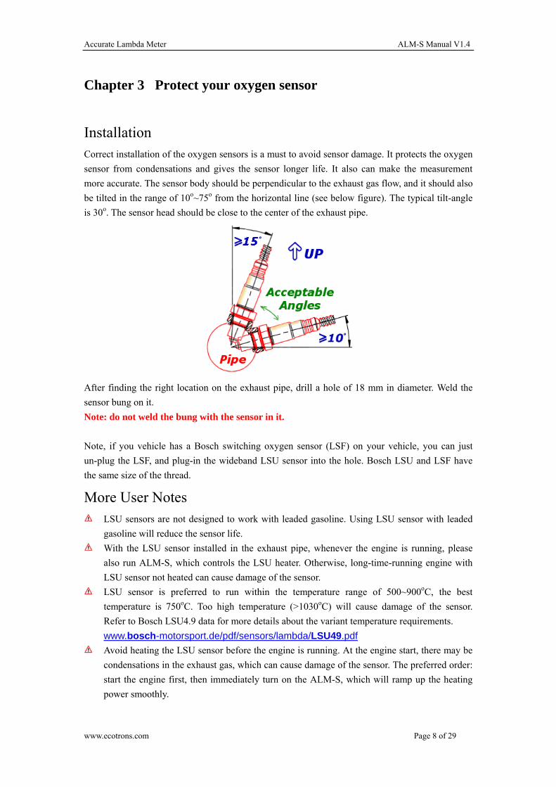
Installation Correct installation of the oxygen sensors is a must to avoid sensor damage. It protects the oxygen
sensor from condensations and gives the sensor longer life. It also can make the measurement
more accurate. The sensor body should be perpendicular to the exhaust gas flow, and it should also
be tilted in the range of 10o~75o from the horizontal line (see below figure). The typical tilt-angle
is 30o. The sensor head should be close to the center of the exhaust pipe.
After finding the right location on the exhaust pipe, drill a hole of 18 mm in diameter. Weld the
sensor bung on it.
Note: do not weld the bung with the sensor in it.
Note, if you vehicle has a Bosch switching oxygen sensor (LSF) on your vehicle, you can just
un-plug the LSF, and plug-in the wideband LSU sensor into the hole. Bosch LSU and LSF have
the same size of the thread.
More User Notes LSU sensors are not designed to work with leaded gasoline. Using LSU sensor with leaded
gasoline will reduce the sensor life.
With the LSU sensor installed in the exhaust pipe, whenever the engine is running, please
also run ALM-S, which controls the LSU heater. Otherwise, long-time-running engine with
LSU sensor not heated can cause damage of the sensor.
LSU sensor is preferred to run within the temperature range of 500~900oC, the best
temperature is 750oC. Too high temperature (>1030oC) will cause damage of the sensor.
Refer to Bosch LSU4.9 data for more details about the variant temperature requirements.
www.bosch-motorsport.de/pdf/sensors/lambda/LSU49.pdf
Avoid heating the LSU sensor before the engine is running. At the engine start, there may be
condensations in the exhaust gas, which can cause damage of the sensor. The preferred order:
start the engine first, then immediately turn on the ALM-S, which will ramp up the heating
power smoothly.
www.ecotrons.com Page 8 of 29
Accurate Lambda Meter ALM-S Manual V1.4
Chapter 4 ALM-S hardware connections
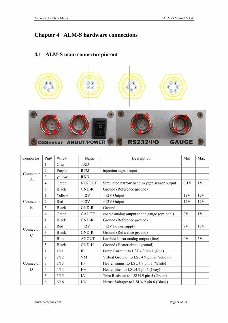
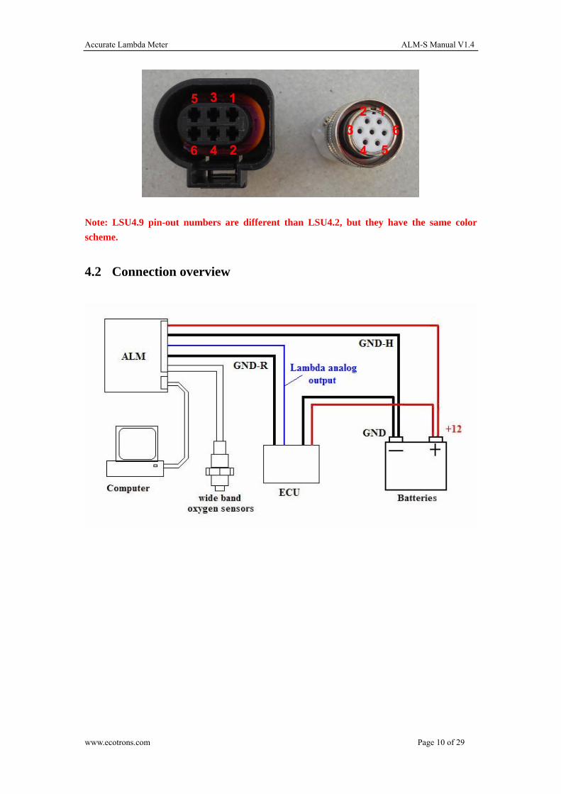
4.1 ALM-S main connector pin-out
Connector Pin# Wire# Name Description Min Max
1 Gray TXD
2 Purple RPM injection signal input
3 yellow RXD
4 Green NO2OUT Simulated narrow band oxygen sensor output 0.1V 1V
Connector
A
5 Black GND-R Ground (Reference ground)
1 Yellow +12V +12V Output 12V 12V
2 Red +12V +12V Output 12V 12V
3 Black GND-R Ground
Connector
B
4 Green GAUGE coarse analog output to the gauge (optional) 0V 1V
1 Black GND-R Ground (Reference ground)
2 Red +12V +12V Power supply 9V 15V
3 Black GND-R Ground (Reference ground)
4 Blue ANOUT Lambda linear analog output (fine) 0V 5V
Connector
C
5 Black GND-H Ground (Heater circuit ground)
1 1/11 IP Pump Current: to LSU4.9 pin 1 (Red)
2 2/12 VM Virtual Ground: to LSU4.9 pin 2 (Yellow)
3 3/13 H- Heater minus: to LSU4.9 pin 3 (White)
4 4/14 H+ Heater plus: to LSU4.9 pin4 (Grey)
5 5/15 IA Trim Resistor: to LSU4.9 pin 5 (Green)
Connector
D
6 6/16 UN Nernst Voltage: to LSU4.9 pin 6 (Black)
www.ecotrons.com Page 9 of 29
Accurate Lambda Meter ALM-S Manual V1.4
Note: LSU4.9 pin-out numbers are different than LSU4.2, but they have the same color
scheme.
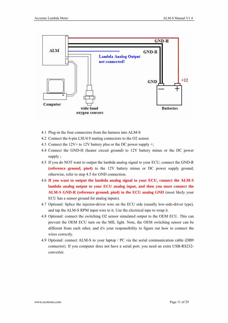
4.2 Connection overview
www.ecotrons.com Page 10 of 29
Accurate Lambda Meter ALM-S Manual V1.4
4.1 Plug-in the four connectors from the harness into ALM-S
4.2 Connect the 6-pin LSU4.9 mating connectors to the O2 sensor.
4.3 Connect the 12V+ to 12V battery plus or the DC power supply +;
4.4 Connect the GND-H (heater circuit ground) to 12V battery minus or the DC power
supply ;
4.5 If you do NOT want to output the lambda analog signal to your ECU, connect the GND-R
(reference ground, pin4) to the 12V battery minus or DC power supply ground;
otherwise, refer to step 4.5 for GND connection.
4.6 If you want to output the lambda analog signal to your ECU, connect the ALM-S
lambda analog output to your ECU analog input, and then you must connect the
ALM-S GND-R (reference ground, pin4) to the ECU analog GND (most likely your
ECU has a sensor ground for analog inputs).
4.7 Optional: Splice the injector-driver wire on the ECU side (usually low-side-driver type),
and tap the ALM-S RPM input wire to it. Use the electrical tape to wrap it.
4.8 Optional: connect the switching O2 sensor simulated output to the OEM ECU. This can
prevent the OEM ECU turn on the MIL light. Note, the OEM switching sensor can be
different from each other, and it's your responsibility to figure out how to connect the
wires correctly.
4.9 Optional: connect ALM-S to your laptop / PC via the serial communication cable (DB9
connector). If you computer does not have a serial port, you need an extra USB-RS232-
converter.
www.ecotrons.com Page 11 of 29

Accurate Lambda Meter ALM-S Manual V1.4
Chapter 5 Software instructions
5.1 Install Software
5.1.1 Setup
Find the software installation folder on the CD, or you can download the latest software
installation package from our website: http://www.ecotrons.com/support.html
5.1.2 Welcome Window
5.1.3 Change Directory
www.ecotrons.com Page 12 of 29
Accurate Lambda Meter ALM-S Manual V1.4
You can change the destination directory if you don't want to install it into the default directory.
Or click the installation button to continue.
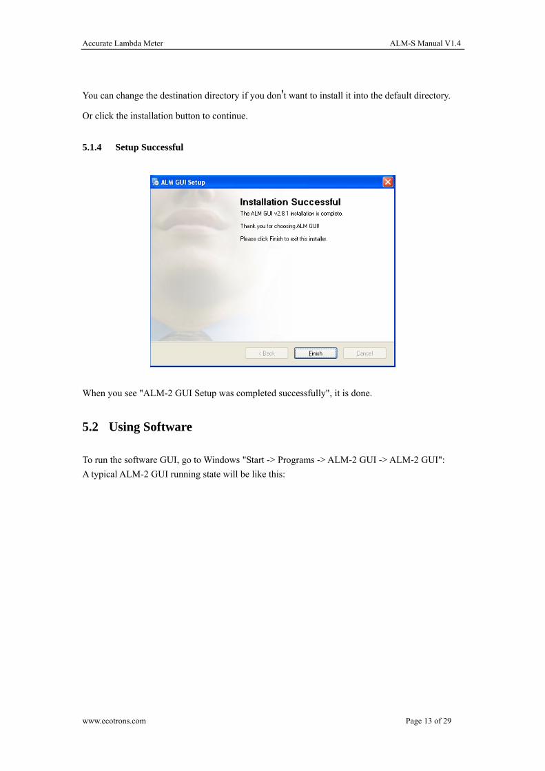
5.1.4 Setup Successful
When you see "ALM-2 GUI Setup was completed successfully", it is done.
5.2 Using Software
To run the software GUI, go to Windows "Start -> Programs -> ALM-2 GUI -> ALM-2 GUI":
A typical ALM-2 GUI running state will be like this:
www.ecotrons.com Page 13 of 29
Accurate Lambda Meter ALM-S Manual V1.4
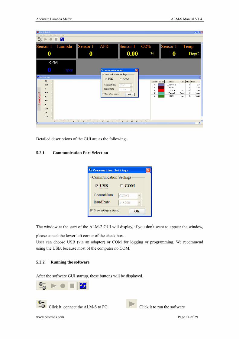
Detailed descriptions of the GUI are as the following.
5.2.1 Communication Port Selection
The window at the start of the ALM-2 GUI will display, if you don't want to appear the window,
please cancel the lower left corner of the check box.
User can choose USB (via an adaptor) or COM for logging or programming. We recommend
using the USB, because most of the computer no COM.
5.2.2 Running the software
After the software GUI startup, these buttons will be displayed.
Click it, connect the ALM-S to PC Click it to run the software
www.ecotrons.com Page 14 of 29

Accurate Lambda Meter ALM-S Manual V1.4
Click it to start recording data Click it to stop recording data
Click it to start the data analysis software
1. Before using the software online, make sure the communication lines between the ALM-S and
the computer has been connected.
2. Click the to connect the computer and ALM-S, The turns green, indicating that
online success.
3. Then click the , The screen displays the values began to change, then you can perform
other operations.
5.2.3 Graph Window
Once connected to the ALM-S, the Graph Window will draw the curves based on the real-time
data. Left side is the axis info. Bottom side is the legends.
The signals that can be displayed in the graph window include:
Lambda
AFR
Oxygen concentration (O2%)
Temp (LSU sensor temperature)
RPM (optional)
www.ecotrons.com Page 15 of 29
Accurate Lambda Meter ALM-S Manual V1.4
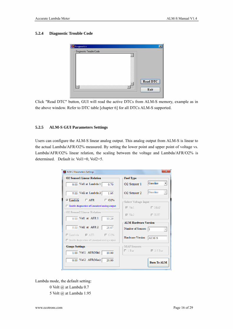
5.2.4 Diagnostic Trouble Code
Click "Read DTC" button, GUI will read the active DTCs from ALM-S memory, example as in
the above window. Refer to DTC table [chapter 6] for all DTCs ALM-S supported.
5.2.5 ALM-S GUI Parameters Settings
Users can configure the ALM-S linear analog output. This analog output from ALM-S is linear to
the actual Lambda/AFR/O2% measured. By setting the lower point and upper point of voltage vs.
Lambda/AFR/O2% linear relation, the scaling between the voltage and Lambda/AFR/O2% is
determined. Default is: Vol1=0, Vol2=5.
Lambda mode, the default setting:
0 Volt @ at Lambda 0.7
5 Volt @ at Lambda 1.95
www.ecotrons.com Page 16 of 29
Accurate Lambda Meter ALM-S Manual V1.4
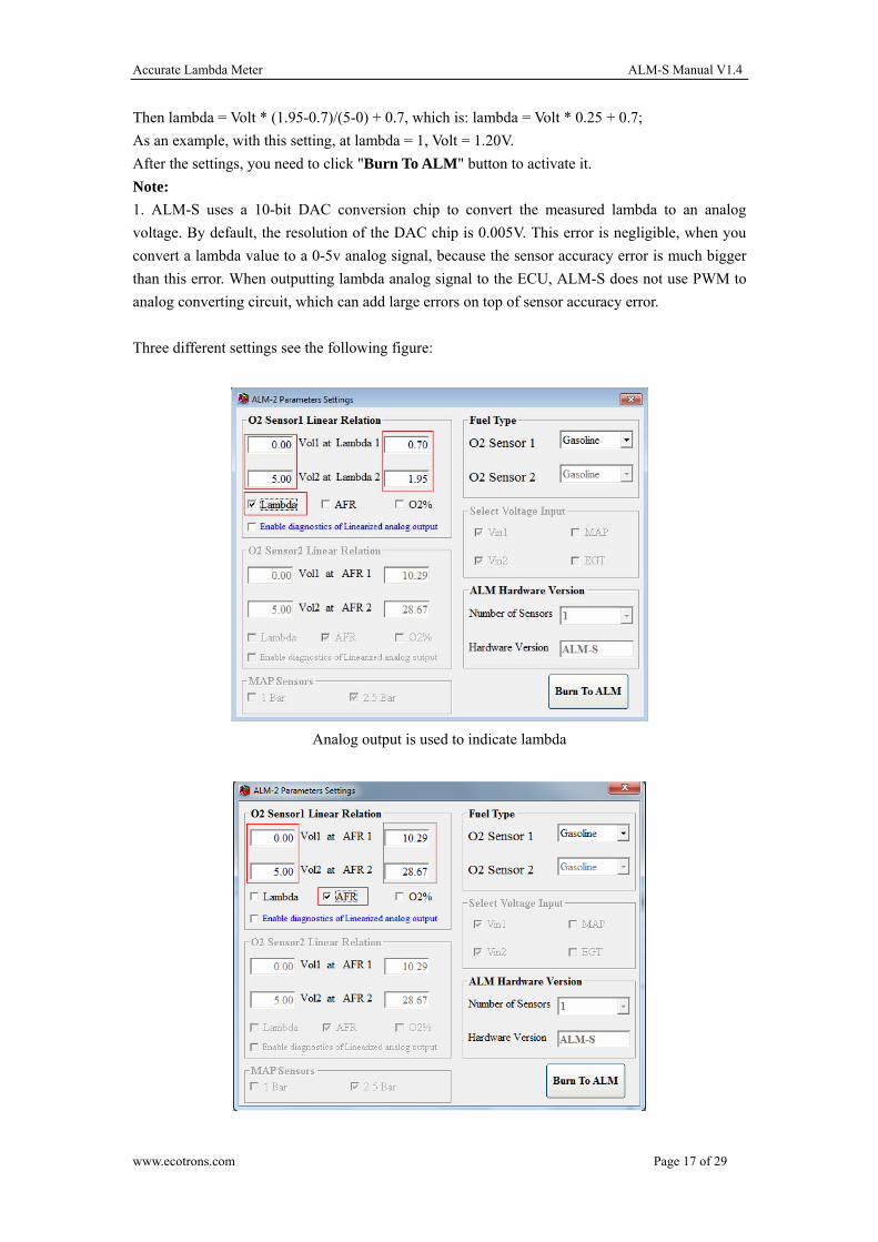
Then lambda = Volt * (1.95-0.7)/(5-0) + 0.7, which is: lambda = Volt * 0.25 + 0.7;
As an example, with this setting, at lambda = 1, Volt = 1.20V.
After the settings, you need to click "Burn To ALM" button to activate it.
Note:
1. ALM-S uses a 10-bit DAC conversion chip to convert the measured lambda to an analog
voltage. By default, the resolution of the DAC chip is 0.005V. This error is negligible, when you
convert a lambda value to a 0-5v analog signal, because the sensor accuracy error is much bigger
than this error. When outputting lambda analog signal to the ECU, ALM-S does not use PWM to
analog converting circuit, which can add large errors on top of sensor accuracy error.
Three different settings see the following figure:
Analog output is used to indicate lambda
www.ecotrons.com Page 17 of 29
Accurate Lambda Meter ALM-S Manual V1.4
Analog output is used to indicate AFR
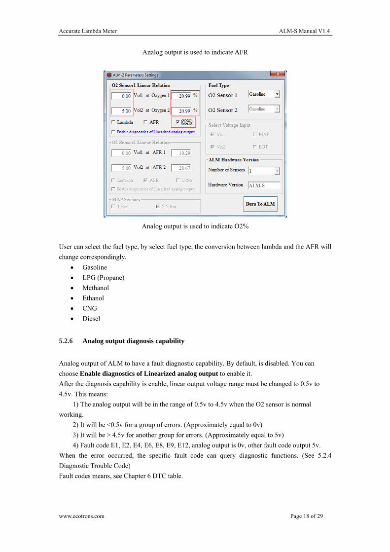
Analog output is used to indicate O2%
User can select the fuel type, by select fuel type, the conversion between lambda and the AFR will
change correspondingly.
Gasoline
LPG (Propane)
Methanol
Ethanol
CNG
Diesel
5.2.6 Analog output diagnosis capability
Analog output of ALM to have a fault diagnostic capability. By default, is disabled. You can
choose Enable diagnostics of Linearized analog output to enable it.
After the diagnosis capability is enable, linear output voltage range must be changed to 0.5v to
4.5v. This means:
1) The analog output will be in the range of 0.5v to 4.5v when the O2 sensor is normal
working.
2) It will be <0.5v for a group of errors. (Approximately equal to 0v)
3) It will be > 4.5v for another group for errors. (Approximately equal to 5v)
4) Fault code E1, E2, E4, E6, E8, E9, E12, analog output is 0v, other fault code output 5v.
When the error occurred, the specific fault code can query diagnostic functions. (See 5.2.4
Diagnostic Trouble Code)
Fault codes means, see Chapter 6 DTC table.
www.ecotrons.com Page 18 of 29
Accurate Lambda Meter ALM-S Manual V1.4
5.2.7 Real-Time Signals
Real-time display of the data sent from ALM-S.
AFR: Air/fuel ratio
Lambda: λ (λ =AFR/14.7 for gasoline)
RPM: Engine speed
Vin1: Analog channels 1
Vin2: Analog channels 2
Temp: LSU Sensor temperature
5.2.8 Data logging and play-back
All real-time data sent from ALM-S to PC GUI can be logged in the CSV file format, which can
be played back with our ALM-S Data Analyzer.
Procedures to log and view data are as follows:
ALM-S Data Analyzer can also run stand-alone. Users can load the previously logged file into it
and do the data analysis in the graphical view.
www.ecotrons.com Page 19 of 29
Accurate Lambda Meter ALM-S Manual V1.4
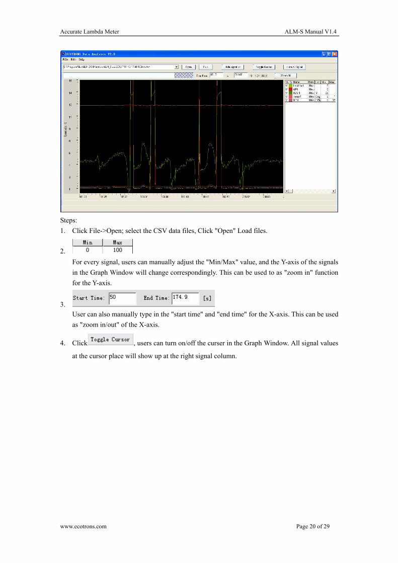
Steps:
1. Click File->Open; select the CSV data files, Click "Open" Load files.
2.
For every signal, users can manually adjust the "Min/Max" value, and the Y-axis of the signals
in the Graph Window will change correspondingly. This can be used to as "zoom in" function
for the Y-axis.
3.
User can also manually type in the "start time" and "end time" for the X-axis. This can be used
as "zoom in/out" of the X-axis.
4. Click , users can turn on/off the curser in the Graph Window. All signal values
at the cursor place will show up at the right signal column.
www.ecotrons.com Page 20 of 29
Accurate Lambda Meter ALM-S Manual V1.4
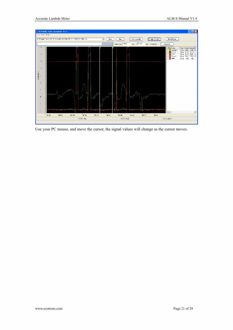
Use your PC mouse, and move the cursor, the signal values will change as the cursor moves.
www.ecotrons.com Page 21 of 29
Accurate Lambda Meter ALM-S Manual V1.4
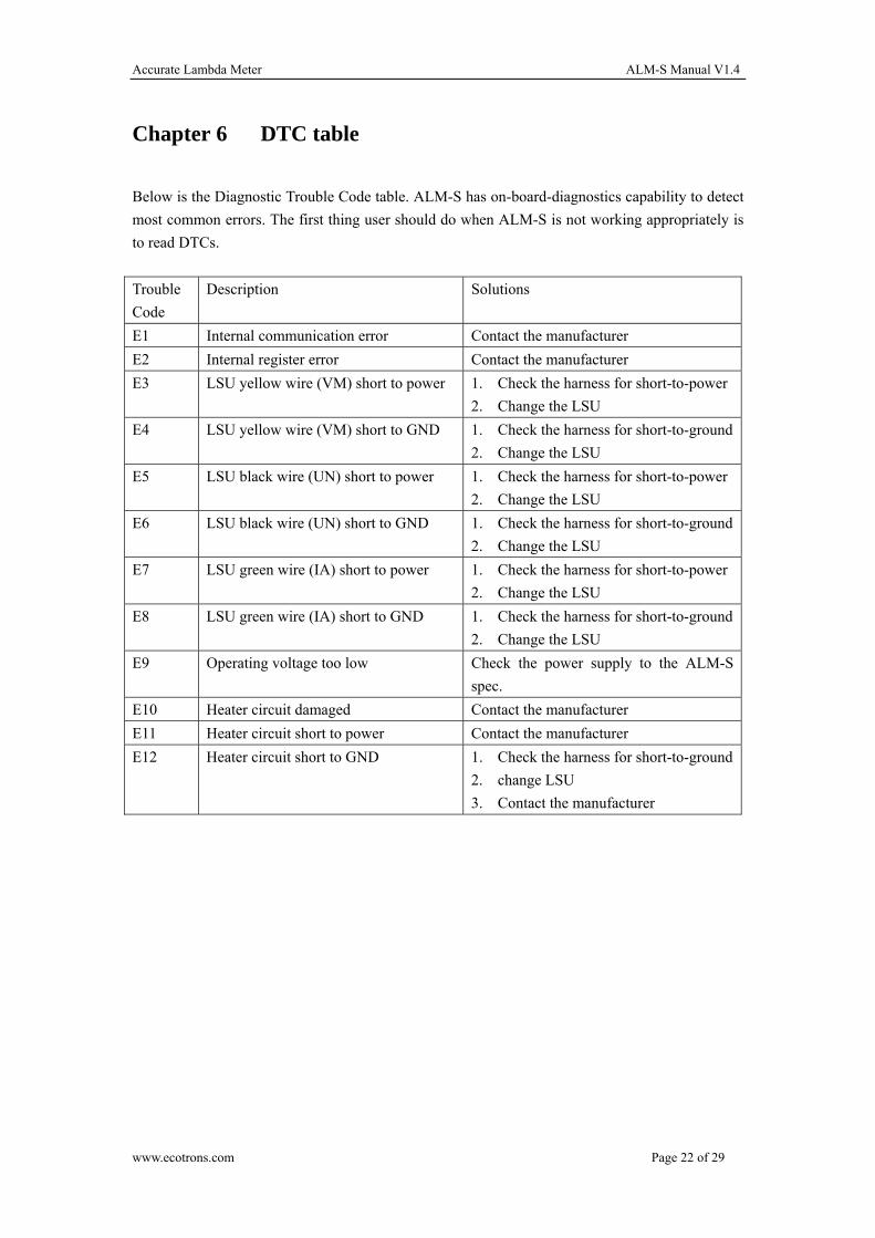
Chapter 6 DTC table
Below is the Diagnostic Trouble Code table. ALM-S has on-board-diagnostics capability to detect
most common errors. The first thing user should do when ALM-S is not working appropriately is
to read DTCs.
Trouble
Code
Description Solutions
E1 Internal communication error Contact the manufacturer
E2 Internal register error Contact the manufacturer
E3 LSU yellow wire (VM) short to power 1. Check the harness for short-to-power
2. Change the LSU
E4 LSU yellow wire (VM) short to GND 1. Check the harness for short-to-ground
2. Change the LSU
E5 LSU black wire (UN) short to power 1. Check the harness for short-to-power
2. Change the LSU
E6 LSU black wire (UN) short to GND 1. Check the harness for short-to-ground
2. Change the LSU
E7 LSU green wire (IA) short to power 1. Check the harness for short-to-power
2. Change the LSU
E8 LSU green wire (IA) short to GND 1. Check the harness for short-to-ground
2. Change the LSU
E9 Operating voltage too low Check the power supply to the ALM-S
spec.
E10 Heater circuit damaged Contact the manufacturer
E11 Heater circuit short to power Contact the manufacturer
E12 Heater circuit short to GND 1. Check the harness for short-to-ground
2. change LSU
3. Contact the manufacturer
www.ecotrons.com Page 22 of 29
Accurate Lambda Meter ALM-S Manual V1.4
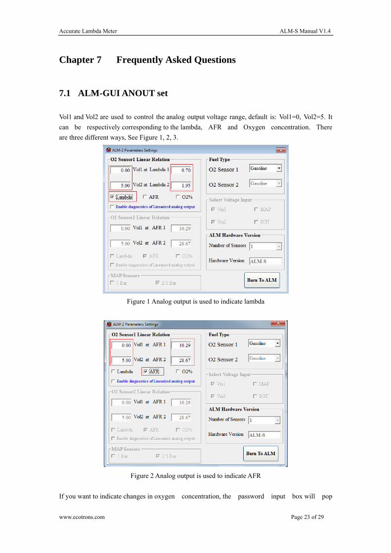
Chapter 7 Frequently Asked Questions
7.1 ALM-GUI ANOUT set
Vol1 and Vol2 are used to control the analog output voltage range, default is: Vol1=0, Vol2=5. It
can be respectively corresponding to the lambda, AFR and Oxygen concentration. There
are three different ways, See Figure 1, 2, 3.
Figure 1 Analog output is used to indicate lambda
Figure 2 Analog output is used to indicate AFR
If you want to indicate changes in oxygen concentration, the password input box will pop
www.ecotrons.com Page 23 of 29
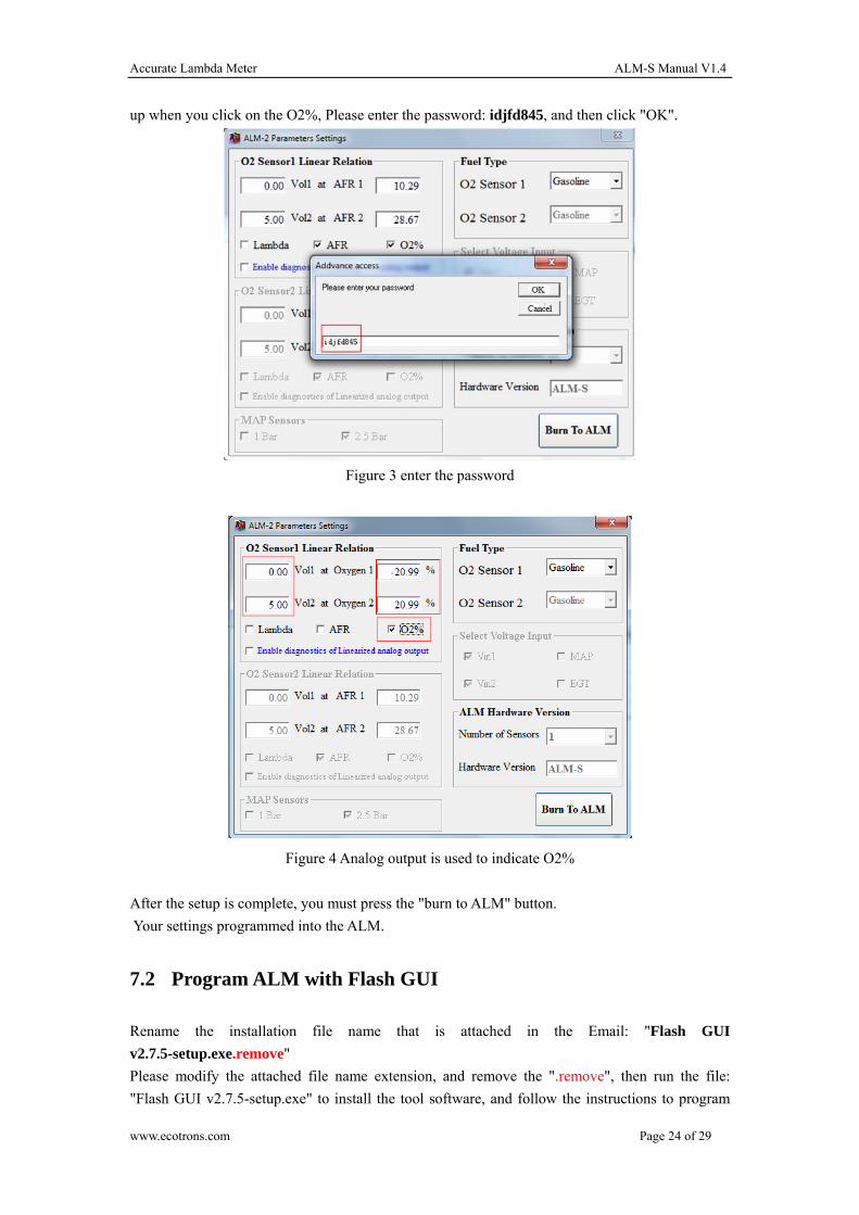
Accurate Lambda Meter ALM-S Manual V1.4
up when you click on the O2%, Please enter the password: idjfd845, and then click "OK".
Figure 3 enter the password
Figure 4 Analog output is used to indicate O2%
After the setup is complete, you must press the "burn to ALM" button.
Your settings programmed into the ALM.
7.2 Program ALM with Flash GUI
Rename the installation file name that is attached in the Email: "Flash GUI
v2.7.5-setup.exe.remove"
Please modify the attached file name extension, and remove the ".remove", then run the file:
"Flash GUI v2.7.5-setup.exe" to install the tool software, and follow the instructions to program
www.ecotrons.com Page 24 of 29
Accurate Lambda Meter ALM-S Manual V1.4
the ECU.
Install and open the "Flash GUI.exe" first.
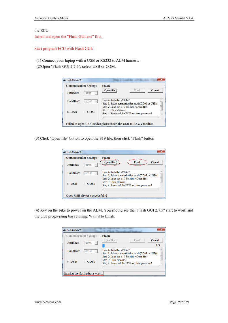
Start program ECU with Flash GUI:
(1) Connect your laptop with a USB or RS232 to ALM harness.
(2)Open "Flash GUI 2.7.5"; select USB or COM.
(3) Click "Open file" button to open the S19 file, then click "Flash" button
(4) Key on the bike to power on the ALM. You should see the "Flash GUI 2.7.5" start to work and
the blue progressing bar running. Wait it to finish.
www.ecotrons.com Page 25 of 29
Accurate Lambda Meter ALM-S Manual V1.4
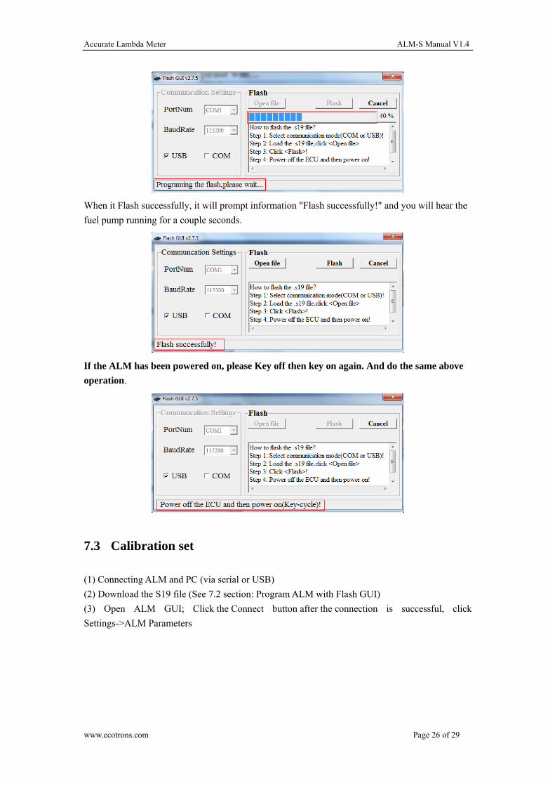
When it Flash successfully, it will prompt information "Flash successfully!" and you will hear the
fuel pump running for a couple seconds.
If the ALM has been powered on, please Key off then key on again. And do the same above
operation.
7.3 Calibration set
(1) Connecting ALM and PC (via serial or USB)
(2) Download the S19 file (See 7.2 section: Program ALM with Flash GUI)
(3) Open ALM GUI; Click the Connect button after the connection is successful, click
Settings->ALM Parameters
www.ecotrons.com Page 26 of 29
Accurate Lambda Meter ALM-S Manual V1.4
(4) Set the analog output (See 7.1 section: ALM-GUI ANOUT set)
7.4 How to calibration ECU readings of ALM analog output
1. Power on the ALM, and launch the ALM GUI (You must install the latest version), connect it to
ALM.
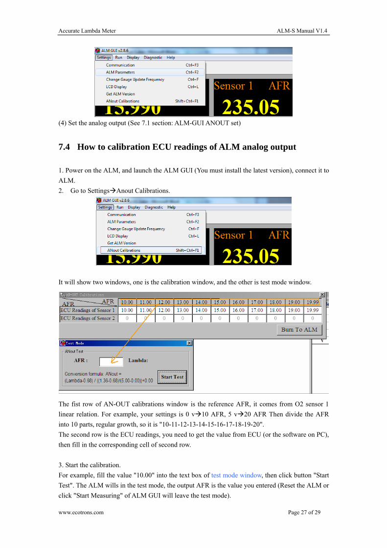
2. Go to SettingsAnout Calibrations.
It will show two windows, one is the calibration window, and the other is test mode window.
The fist row of AN-OUT calibrations window is the reference AFR, it comes from O2 sensor 1
linear relation. For example, your settings is 0 v10 AFR, 5 v20 AFR Then divide the AFR
into 10 parts, regular growth, so it is "10-11-12-13-14-15-16-17-18-19-20".
The second row is the ECU readings, you need to get the value from ECU (or the software on PC),
then fill in the corresponding cell of second row.
3. Start the calibration.
For example, fill the value "10.00" into the text box of test mode window, then click button "Start
Test". The ALM wills in the test mode, the output AFR is the value you entered (Reset the ALM or
click "Start Measuring" of ALM GUI will leave the test mode).
www.ecotrons.com Page 27 of 29
Accurate Lambda Meter ALM-S Manual V1.4
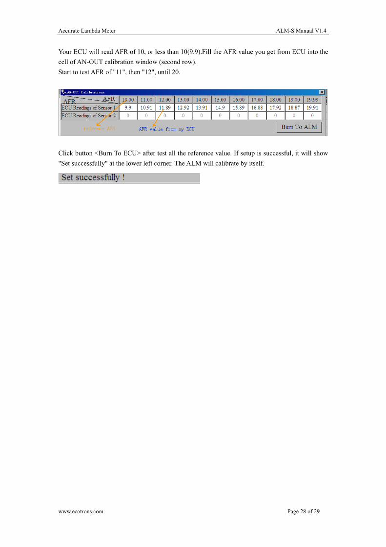
Your ECU will read AFR of 10, or less than 10(9.9).Fill the AFR value you get from ECU into the
cell of AN-OUT calibration window (second row).
Start to test AFR of "11", then "12", until 20.
Click button <Burn To ECU> after test all the reference value. If setup is successful, it will show
"Set successfully" at the lower left corner. The ALM will calibrate by itself.
www.ecotrons.com Page 28 of 29
Accurate Lambda Meter ALM-S Manual V1.4
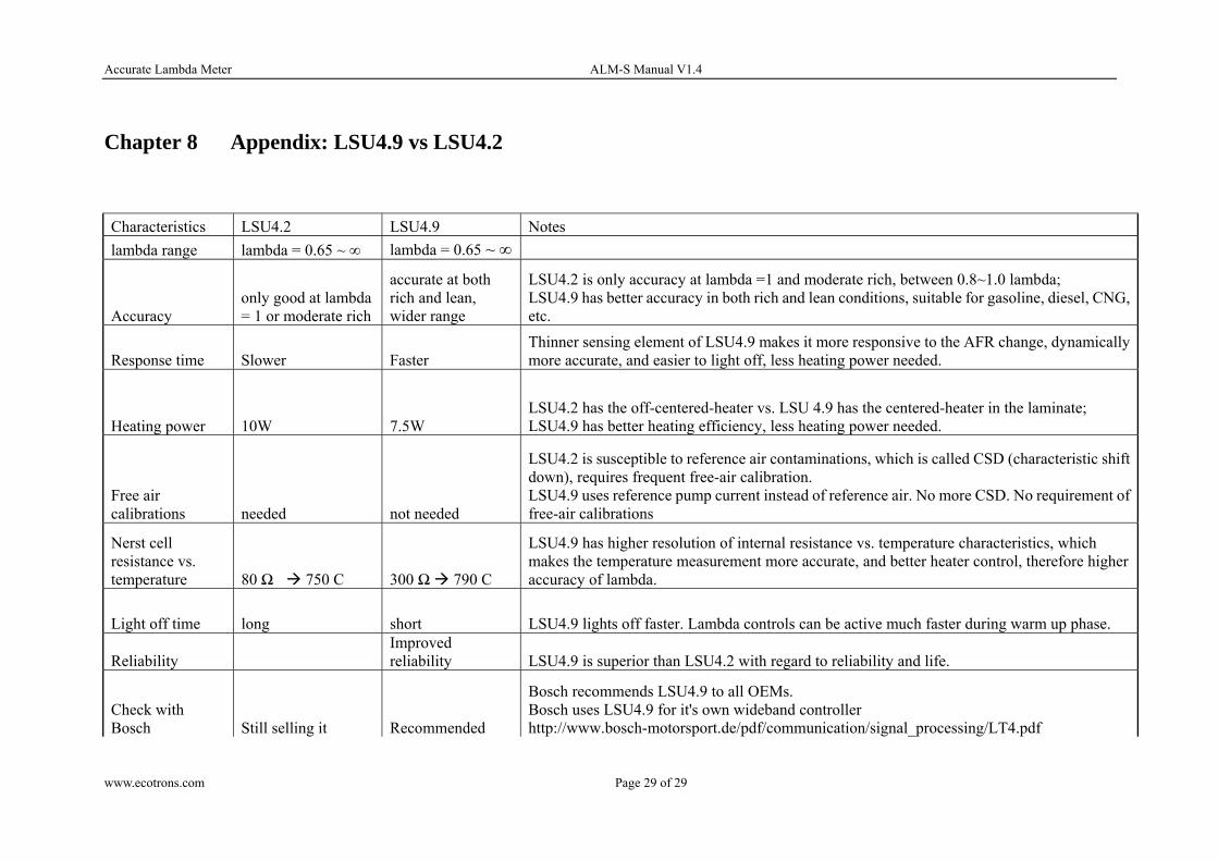
Chapter 8 Appendix: LSU4.9 vs LSU4.2
Characteristics LSU4.2 LSU4.9 Notes
lambda range lambda = 0.65 ~ ∞ lambda = 0.65 ~ ∞
Accuracy only good at lambda = 1 or moderate rich
accurate at both rich and lean, wider range
LSU4.2 is only accuracy at lambda =1 and moderate rich, between 0.8~1.0 lambda; LSU4.9 has better accuracy in both rich and lean conditions, suitable for gasoline, diesel, CNG, etc.
Response time Slower Faster Thinner sensing element of LSU4.9 makes it more responsive to the AFR change, dynamically more accurate, and easier to light off, less heating power needed.
Heating power 10W 7.5W LSU4.2 has the off-centered-heater vs. LSU 4.9 has the centered-heater in the laminate; LSU4.9 has better heating efficiency, less heating power needed.
Free air calibrations needed not needed
LSU4.2 is susceptible to reference air contaminations, which is called CSD (characteristic shift down), requires frequent free-air calibration. LSU4.9 uses reference pump current instead of reference air. No more CSD. No requirement of free-air calibrations
Nerst cell resistance vs. temperature 80 Ω 750 C 300 Ω 790 C
LSU4.9 has higher resolution of internal resistance vs. temperature characteristics, which makes the temperature measurement more accurate, and better heater control, therefore higher accuracy of lambda.
Light off time long short LSU4.9 lights off faster. Lambda controls can be active much faster during warm up phase.
Reliability Improved reliability LSU4.9 is superior than LSU4.2 with regard to reliability and life.
Check with Bosch Still selling it Recommended
Bosch recommends LSU4.9 to all OEMs. Bosch uses LSU4.9 for it's own wideband controller http://www.bosch-motorsport.de/pdf/communication/signal_processing/LT4.pdf
www.ecotrons.com Page 29 of 29