Embed Size (px)
Citation preview

ARES 200 TecARES 250 TecARES 300 TecARES 350 Tec
Floor standing, high output, modular condensing boilers
Installation and Servicing Instructions
Leave these instructions with the Building Manager
ARES Tec

2Alpha ARES Tec 200 - 350

3 Alpha ARES Tec 200 - 350
This manual contains instructions for use by Gas Safe registered installers and/or maintenance engineers, in compliance with Gas Safe and current British Standards.The manufacturer will not be held liable in the case of damage to people, animals or property due to the failure to observe the instructions supplied with the boiler.
1 General information ...................................................................41.1 Symbols used in the manual ........................................................41.2 Compliant use of the appliance ...................................................41.3 Information to be provided to the user .....................................41.4 Safety warnings .............................................................................51.5 Regulations for installation..........................................................61.6 Installation .....................................................................................61.7 Water treatment ............................................................................71.8 General warnings ..........................................................................8
2 Technical data and dimensions ..................................................92.1 Technical data ................................................................................92.2 View of main components .........................................................102.3 Dimensions ..................................................................................112.4 Operating data / general data ....................................................12
3 Instructions for installation .....................................................133.1 General recommendations ........................................................133.2 Packaging .....................................................................................143.3 Removing the boiler from the pallet and fitting the feet .......153.4 Positioning the boiler .................................................................163.5 Connecting the boiler ................................................................173.6 Gas connection............................................................................183.7 System flow and return pipe connection .................................193.8 Additional safety, protection and control devices ..................203.9 Hydraulic separator ....................................................................213.10 Hydraulic system filter ...............................................................213.11 Determining the primary circuit pump or boiler pump .......223.12 Valves ............................................................................................22
3.13 Complete optional kits ...............................................................233.14 Condensate drain ........................................................................243.15 Connecting the flue ....................................................................253.16 Flue manifold connection ..........................................................253.17 Electrical connections ................................................................27
General recommendations ........................................................27230/240 V electrical supply connection ...................................28
3.18 Wiring diagram for additional safety devices .........................283.19 Connection diagram ..................................................................29
Power supply, gas valve, safety group, On/Off pump, external sensor, flow switch. ..........................................29Power supply, gas valve, safety group, modulating pump, external sensor, flow switch. ......................................................29Safety group safety connection (supplied with modulating pump). ..........................................30On/Off thermostat connection. ................................................30Modulating room thermostats connection. ............................31Modulating zone manager connection. ...................................31
3.20 Practical connection diagram ...................................................323.21 Connections and management diagram ..................................343.22 Examples of installation (functional diagram and
description of connections) .......................................................363.23 System filling and draining ........................................................413.24 Boiler frost protection ................................................................413.25 Check and adjust the CO2 values ..............................................42
Nozzles - pressures. ....................................................................433.26 Emergency and safety operations ............................................453.27 First ignition ................................................................................46
4 Inspections and maintenance ..................................................47
INDEX

4
General information
Alpha ARES Tec 200 - 350
1.2 CoMpLIANT uSE of ThE AppLIANCE
The Alpha ARES Tec appliance was built to current standards in place. Nevertheless, following improper use the safety and life of the user or other people may be exposed to danger, i.e. damage to the appliance or other objects. The appliance is designed for operation in hot water circulating heating systems.Any other use is considered unsuitable. The manufacturer will not be held liable for any damage resulting from improper use. Any use in accordance with the envisioned purposes includes the strict observance of the instructions in this manual.
1.3 INfoRMATIoN To BE pRovIDED To ThE uSER
The user must be instructed in the use and operation of the heating system, in particular:• Hand these instructions to the user, as well as the other documents relative to the appliance contained in the packaging in an
envelope. The user must keep this documentation safe so that it is available for future consultation. • Inform the user of the importance of ventilation and the flue/condensate system, highlighting how essential they are and how
it is strictly forbidden to change them. • Inform the user on how to control the water pressure in the system as well as the operations required to restore it. • Inform the user on how to correctly regulate the temperature, control units/thermostats and radiators in order to save energy.• If the appliance is sold or transferred to another owner or if the owner moves, leaving the appliance behind, always ensure the
manual accompanies the appliance so that it may be consulted by the new owner and/or installer.• It is recommended that servicing is carried out on an annual basis by a Gas Safe registered engineer.
The manufacturer will not be held liable in the case of damage to people, animals or property due to the failure to observe the instructions contained in this manual.
1 GENERAL INfoRMATIoN
1.1 SyMBoLS uSED IN ThIS MANuAL
When reading through this manual, pay special attention to the parts marked with these symbols:
DANGER!Serious danger to
safety and life
ATTENTIoN!possibly dangerous situation
for the product and environment
NoTE!Tips for the user
5
General information
Alpha ARES Tec 200 - 350
1.4 SAfETy wARNINGS
ATTENTIoN!The appliance must not be used by people with reduced physical, mental and sensorial capabilities, without experience and knowledge. These people must be duly instructed and supervised during manoeuvring operations.
ATTENTIoN!Installation, adjustment and maintenance of the appliance must be carried out by a Gas Safe registered engineer.
DANGER!Maintenance or repair work on the boiler must be carried out by a Gas Safe registered engineer, it is advisable to have an annual maintenance contract.poor or irregular maintenance can compromise the operational safety of the appliance and cause damage to people, animals and property for which the manufacturer will not be held liable.
Changes to parts connected to the applianceDo not make changes to the following elements: • To the boiler.• To the gas, air, water and power supply lines.• To the flue pipe, safety valve and condensate pipe.• To the constructive elements that affect the operational safety of the appliance.
ATTENTIoN!To tighten or loosen any threaded fittings, use suitable tools only.Improper use and/or unsuitable tools can cause damage (i.e. water and gas leaks).
ATTENTIoN!Instructions for appliances running on LpG gas Make sure that the gas tank has been ventilated prior to installing the appliance. For a thorough ventilation of the tank contact the liquid gas supplier and in any case authorised personnel, in accordance with the law. Ignition problems can arise if the tank is not thoroughly ventilated. In this case contact the liquid gas tank supplier.
Smell of gasIn case of the smell of gas observe the following safety instructions: • Do not smoke or strike matches.• Do not turn electrical switches on or off.• Do turn off the gas supply immediately.• Do extinguish all sources of ignition.• Do ventilate the room where the gas leak occurred.• Do contact the National Gas Emergency Service on 0800 111 999.
Explosive and easily flammable substances Do not use or deposit explosive or easily flammable materials (i.e. petrol, paints, paper, wood) in the room where the appliance is installed.
ATTENTIoN!The heating unit must be installed so as to avoid it from freezing and exposing the controls to temperatures below -15°C and over +40°C.The heating unit must be protected by:• Insulating the water and condensate pipes.• Adopting specific anti-freeze products in the water system.

6
General information
Alpha ARES Tec 200 - 350
1.5 REGuLATIoNS foR INSTALLATIoN
The Alpha ARES Tec boiler is a gas category II2h3p heating unit.
The appliance must be installed in accordance with the instructions contained in this manual.
Installation must be carried out by a Gas Safe registered engineer.Gas Safe Register - 0800 408 5577 - www.gassaferegister.co.uk
It is necessary to observe the standards, regulations and requirements for installation provided below, constituting a rough and non-exhaustive list, in order to follow the changes in regulations. we would like to underline that updating the list of standards is the responsibility of the engineers authorised to carry out installation.
Also observe the standards regarding the heating control unit, construction regulations and requirements on combustion heating in the country of installation.
The appliance must be installed, commissioned and subject to maintenance in accordance with all current regulations in force. This also applies to the water system, the flue and condensate disposal systems, the installation room and the electrical system.
failure to observe the above regulations will void the warranty.
ATTENTIoN! If the new boiler has been fitted in an old system without it being thoroughly cleaned and flushed, do not clean the system, as any sediments in the system may fill the heat exchanger with residues after replacement. It is advisable to contact a company specialised in water treatment.
If the ARES Tec boiler is being installed on a new system it is still advisable to clean it thoroughly, using products that are suitable for the entire system, and install a Y-strainer with two isolation valves on the return pipe to the boiler, so that it can be cleaned as needed.This filter will protect the boiler from sediments coming from the heating system.
In both cases it is necessary to keep the head losses localised in the primary circuit, for the correct sizing of the pump.
1.6 INSTALLATIoN
If the ARES Tec boiler is installed on existing systems, make sure that:• The flue is suitable for condensing appliances, for the temperatures
of the combustion products, calculated and built in accordance with regulations in force. That it is as straight as possible, water-tight and insulated and does not have any obstructions or constrictions.
• The flue is equipped with an attachment to remove the condensation.• The heating control unit is equipped with a pipe for the removal of
the condensation produced by the boiler.• The electrical system is built in accordance with specific regulations
and by qualified technical personnel.• The flow rate, head and direction of flow of the circulation pump
must be appropriate for the system.• The gas supply line and any existing tanks are set up in accordance
with regulations in force.• Ensure expansion vessels are correctly sized for the system to
accommodate the expansion of heated water.• Ensure the system has been thoroughly cleaned and flushed.

7
General information
Alpha ARES Tec 200 - 350
1.7 wATER TREATMENT
Treating the supply water allows you to prevent problems and maintain the functionality and efficiency of the boiler over time.
The purpose of this treatment is to eliminate or significantly reduce problems that can be outlined as:build-upcorrosionsedimentsbiological growth (mould, fungus, algae, bacteria, etc.).
The chemical analysis of the water provides a lot of information on the state and "health" of the system.The pH level is a numerical indication of the acidity or alkalinity of a solution. The pH scale goes from 0 to 14, where 7 corresponds to neutral. Values below 7 indicate acidity, values above 7 indicate alkalinity.The ideal ph value in heating systems with aluminium boilers is between 6.5 and 8, with a hardness of 15°f.Water in a system with a pH value outside of this range considerably accelerates the destruction of the protective oxide layer which forms naturally inside the aluminium bodies, and would not occur naturally: if the pH level is lower than 6 it contains acid, if it is above 8 the water is alkaline, either due to an alkaline treatment (for example phosphates or glycols operating as antifreeze) or in some cases the natural generation of alkalis in the system.Vice versa, if the pH value is between 6.5 and 8, the aluminium surfaces in the body are passivated and protected from further corrosive attacks.To minimise corrosion, it is essential to use a corrosion inhibitor. In order for it to work efficiently, however, the metal surfaces must be clean.when using inhibitors or cleaning agents they must be applied in accordance with their manufacturers instructions. only products from fernox and Sentinel are acceptable for use with AresTec boilers. further information can be obtained from fernox (Tel: 01799 521133) or Sentinel (Tel: 01928 588330)
The best inhibitors on the market also contain an aluminium protection system that stabilises the ph levels of the filler water, preventing sudden changes (buffer effect).It is advisable to systematically check (at least twice a year) the ph value of the water in the system. In order to do so a chemical laboratory analysis is not required, but a simple check using a analysis "kit" contained in a carry case, easily available on the market.
ThE pRESSuRISATIoN uNIT, EXpANSIoN vESSELS AND fILLING Loop MuST BE SET up oN ThE RETuRN pIpE To ThE pRIMARy CIRCuIT DowNSTREAM of ThE puMp.
Precautions are required to avoid the formation and localisation of oxygen in the water of the system, for example plastic pipes used in the under-floor heating systems must not be permeable to oxygen.
Make sure that any anti-freeze products are compatible with aluminium and any other parts and materials in the system.
ATTENTIoN!Any damage caused to the boiler, due to the formation of build-up or corrosive water, will not be covered by the warranty.
ATTENTIoN!These appliances are designed and developed to transfer heat to a heat carrying fluid possessing the characteristics described here, they are not suitable to directly heat water intended for human consumption.

8
General information
Alpha ARES Tec 200 - 350
1.8 GENERAL wARNINGS
The instruction manual is an integral and essential part of the product and must be kept safe by the individual in charge of the system.
Read the warnings contained in the manual carefully, as they provide important instructions regarding installation, user and maintenance safety.
Keep the manual safe for future use.
The appliance must be installed and maintained in accordance with current regulations in force, adhering to the instructions of the manufacturer, and by Gas Safe registered engineers, in accordance to regulations in force.
Incorrect installation or poor maintenance can cause injury to persons and animals and damage to property, for which the manufacturer is not liable.
Before carrying out any servicing or maintenance operations on the boiler, isolate it's electrical supply and close the appliance gas valve.
Do not obstruct the ventilation openings, flue terminal or condensate pipe outlet.
In case of breakdown and/or poor operation of the appliance, switch it off, and do not attempt in any way to repair it or intervene directly. Only contact personnel that has been authorised in accordance with the law.
Any repairs to the products must be carried out by authorised Alpha personnel only, using original spare parts only. Failure to observe the above can jeopardise the safety of the appliance and will void the warranty.
To guarantee the efficiency of the appliance and its correct operation it is essential for authorised personnel to carry out annual maintenance.
If the appliance is put out of use for downtime, any part that is susceptible to posing a potential source of danger must be made safe.
Before re-commissioning an appliance that has been put out of use, flush the domestic hot water system ensuring that the water has been completely changed.
If the appliance is sold or transferred to another owner or if the owner moves, leaving the appliance behind, always ensure the manual accompanies the appliance so that it may be consulted by the new owner and/or installer.
All appliances with options or kits (including electric) must only use original spare parts.
The appliance must only be employed for its expressly foreseen use. Any other use must be considered improper and therefore dangerous.

9
Technical data and dimensions
Alpha ARES Tec 200 - 350
2 TEChNICAL DATA AND DIMENSIoNS
2.1 TEChNICAL DATA
• A condensing boiler comprised of heating modules designed to operate on their own or in a set.
• Can be installed inside or outside (IP X5D).• Low water content.• Quick response time to load changes.• Single pipe flue that can be positioned on 3 sides.• Reversible flow and return manifolds (para. 3.5).• Reversible single gas supply pipe.• Comprised of 4 or more heating modules (between 4 and 7),
aluminium/silicon/magnesium casting.• Including low NOx premix modulating burners.• None of the heating modules have hydraulic cut-off devices.• Modulated output between 12 to 50 kW/module.
TEMPERATURE CONTROL DEVICES:• Temperature sensor (each heating module).• Limit Thermostat (each heating module).• Flow temperature sensor (manifold).• Return temperature sensor (manifold).• Approved safety thermostat (To be ordered and installed on safety
group, see Section 3.8).• GCI global flow probe.
OTHER SAFETY DEVICES:• See Section 3.8.
POP-UP control panel comprising:• On/Off switch (see Section 3.26).• TGC (boiler thermoregulation/manager).• GCI (internal cascade management board).• Protection fuses.• Any limit thermostats (only models over 350 kW).• Fan air pressure switch.• Condensate level sensor.• Gas pressure switch.• Flue pressure switch (anti-obstruction).• Single temperature control sensors for the combined modules on
the flow and return manifolds.
• Integral insulation with non-allergenic synthetic wool.• Modulating premix burner.• Sound emissions at maximum output below 49 dBA.• Operation during heating: determining the required input through
a control microprocessor, with preset comparison parameters between requested temperature (or calculated by the outdoor thermoregulation) and overall flow temperature.
• Logic of operation: • Possibility of controlling the output of the single heating modules
for calibration and/or assistance with reserved access code.• DHW production through priority temperature probe, to control
the storage tank temperature through a pump or three-way diverter valve through the supplied TGC thermoregulator.
• Possibility of controlling the output of the single heating modules.• Heat request control: temperature set point and modulation level.• Monitoring the state of operation and temperatures.• Alarm notification.• Parameter setting.• Control relay to switch on a pump at a fixed speed.• Analogue 0 to 10 V output to control a modulating pump.• Emergency operation: this allows you to avoid system down time
due to an interruption in communication with the E8 control unit.• The possibility of selecting the emergency temperature through
supplied 'Constant Set point' heating elements: 70°C, maximum of 50% output.
• Alarm management.• Alarm reset input.• Alarm notification Relay.• Easily removable integral panelling comprised of oven-painted steel
panels suitable for outdoor installation.• Condensate collection tray with stainless steel flue trap and flue
chamber.• Incorporated automatic air vent.The request for heat can be generated by the TGC thermoregulation/manager or alternatively by the GCI (internal cascade management board).The management logic envisions simultaneous operation of the maximum number of heating modules, so as to always obtain the maximum efficiency. Since it guarantees the maximum exchange area based on the delivered power. The modules are made to operate so as to equally divide the operating time.The hot water that is produced is circulated by the manifold pump located on the return of the primary circuit to the flow of the hydraulic separator. From here other pumps (see suggested system diagrams in para. 3.21) circulate the flow to the various circuits. The return water enters the hydraulic separator, to start the cycle again.

10
Technical data and dimensions
Alpha ARES Tec 200 - 350
2.2 vIEw of MAIN CoMpoNENTS
flue outlet RIGHT side (as supplied) - LEFT side and REAR side (order rear flue gas outlet kit)flow RIGHT side (as supplied) - LEFT side Return RIGHT side (as supplied) - LEFT side Gas pipe RIGHT side (as supplied) - LEFT side
To re-position the flue outlet to the left side of the boiler, it is necessary to move cover 'A' with relative cabling, level sensor and pressure switch pipe, to the rear side of the boiler. The rear cover (previously removed) must be put back on the right side of the boiler.
Min. depth 100 mm
Fan
Gas Pipe Connection
Burner Cover
Ignition ElectrodeFlame Sensing Electrode
Burner
Heat Exchanger
Condensate Outlet
Return TemperatureSensor
Heating Return
Heating Flow
Flow TemperatureSensor
Automatic Air Vent
Limit Thermostat
Drain PointCondensate CollectionTray/Flue Fitting
Frame
Gas Valve
Condensate Level Sensor
Control Panel
Primary Temperature Sensor
A

11
Technical data and dimensions
Alpha ARES Tec 200 - 350
W
H (
1150
)
W1
70
106
Condensate drain
120
*
F
R
G
750
390
275
833
255 276
352 353
(D1) 705
20
387 384
D (770)
318
2.3 DIMENSIoNSFRONT VIEW RIGHT SIDE VIEW
(As supplied, for left side attachments)
TOP VIEW
LEFT SIDE VIEW
(*) ARES Tec 200, 250 and 300 Terminal inside the casing
ARES Tec 200 250 300 350Dimensions UnitHeating elements No. off 4 5 6 7Height 'H' mm 1150 1150 1150 1150Width 'W' mm 1032 1032 1300 1300Width 'W1' mm 974 974 1242 1242 Depth 'D' mm 770 770 770 770Depth 'D1' mm 705 705 705 705Attachment sizesGas connection 'G' BSP 2 2 2 2System flow 'F' BSP 2½ 2½ 2½ 2½System return 'R' BSP 2½ 2½ 2½ 2½Flue diameter mm 150 200 200 200Condensate drain diameter mm 40 40 40 40
Left sideflowpre-cut section
Left sidereturnpre-cut section
Left sidegaspre-cut section

12
Technical data and dimensions
Alpha ARES Tec 200 - 350
2.4 pERfoRMANCE DATA / GENERAL DATA
(*) Room Temperature = 20°C (**) See 'NOZZLES - PRESSURES' table, Section 3.24.(***) The IP X5D degree of protection is obtained with the lid lowered.
ARES Tec 200 250 300 350Boiler category II2H3P II2H3P II2H3P II2H3P
Nominal heat input on L.C.V. Qn kW 200 250 300 348Minimum heat input on L.C.V. Qmin kW 12 12 12 12Nominal effective output (Tr 60 / Tf 80°C) Pn kW 195.2 244.5 294.0 342.2 Minimum effective ouput (Tr 60 / Tf 80°C) Pn min kW 11.7 11.7 11.7 11.7Nominal effective output (Tr 30 / Tf 50°C) Pcond kW 200.4 251.3 302.7 354.6Minimum effective output (Tr 30 / Tf 50°C) Pcond min kW 12.5 12.5 12.5 12.5 Efficiency at nominal output (Tr 60 / Tf 80°C) % 97.6 97.8 98.0 98.2 Efficiency at minimum output (Tr 60 / Tf 80°C) % 97.16 97.16 97.16 97.16 Efficiency at nominal output (Tr 30 / Tf 50°C) % 100.2 100.5 100.9 101.9 Efficiency at minimum output (Tr 30 / Tf 50°C) % 106.5 106.5 106.5 106.5 Efficiency class according to directive 92/42 EEC -- 4 4 4 4 Combustion efficiency at nominal load % 97.8 98.0 98.1 98.3Combustion efficiency at minimum load % 98.3 98.3 98.3 98.3Losses from operating burner casing % 0.2 0.2 0.1 0.1Losses from burner casing when switched off -- 0.1 0.1 0.1 0.1Flue temperature at net of Tf-Ta (max) °C 46.5 47.3 48.2 49.1Maximum flue flow rate (max) kg/h 326.9 408.6 490.3 572Air excess % 25.5 25.5 25.5 25.5 (**) CO2 (min/max) % - - - -NOX (weighted value according to EN 15420) mg/kWh 53.8 53.8 53.8 53.8 NOX class -- 5 5 5 5Flue losses with burner in operation (max) % 2.2 2.0 1.9 1.7Water flow rate at nominal power (∆T 20°C) l/h 8394 10514 12642 14784Minimum pressure of heating circuit bar 0.5 0.5 0.5 0.5Maximum pressure of heating circuit bar 6 6 6 6Water content l 18.3 22.4 26.5 30.6NG consumption G20 (supp.press. 20 mbar) at Qn m3/h 21.1 26.4 31.7 37.0NG consumption G20 (supp.press. 20 mbar) at Qmin m3/h 1.3 1.3 1.3 1.3 LPG consumption (supp.press. 37 to 50 mbar) at Qn kg/h 15.5 19.4 23.3 27.2LPG consumption (supp.press. 37 to 50 mbar) at Qmin kg/h 0.9 0.9 0.9 0.9Maximum pressure available at flue base Pa 100 100 100 100 Max condensate production kg/h 30.6 38.3 45.9 53.6EmissionsCO with 0% of O2 in the exhaust ppm <77 <77 <77 <77 NOx with 0% of O2 in the exhaust ppm <44 <44 <44 <44 Sound dBA <49 <49 <49 <49 Electrical dataSupply voltage / Frequency V/Hz 230/50 230/50 230/50 230/50 Supply fuse A 4 4 4 4Power consumption W 290 362 435 507(***) Degree of protection IP X5D X5D X5D X5DPower consumption in stand-by W 10 10 10 10

13
Instructions for the installer
Alpha ARES Tec 200 - 350
3 INSTRuCTIoNS foR INSTALLATIoN
3.1 GENERAL RECoMMENDATIoNS
ATTENTIoN!This boiler must only be employed for its intended use. Any other use must be considered improper and therefore dangerous.This boiler is used to heat water to below boiling temperature at atmospheric pressure.
ATTENTIoN! These appliances are designed exclusively for installation inside suitable boiler rooms.
Before connecting the boiler, have professionally qualified personnel:a) flush and clean all of the pipes in the system to
remove any residues or sediment that could stop the boiler from running efficiently.
b) Make sure the boiler is set up to operate with the correct type of fuel. The type of fuel is stated on the packaging and technical data plate.
c) Make sure that the flue has been designed correctly to completely remove the products of combustion.
d) Ensure that the flue has an adequate draught, that it is not blocked, and that there are no flues from other appliances connected to it.
Only once these checks have been carried out can the boiler be connected to the flue.
ATTENTIoN!In atmospheres with aggressive vapour or dust, the appliance must operate independently of the air in the room in which it is installed!
ATTENTIoN!The appliance must be installed by Gas Safe Registered engineers.
ATTENTION! Ensure there is adequate clearance to install the appliance and provide sufficient clearance for maintenance.
The boiler must be connected to a heating system compatibly with its specifications and output.

14
Instructions for the installer
Alpha ARES Tec 200 - 350
C
B A
3.2 pACkAGING
The ARES Tec boiler is supplied assembled in a box on a pallet.
Once the two straps have been removed, lift the box off from the top and make sure the contents are intact.
Packaging materials (cardboard box, straps, plastic bags, etc.) constitute a potential hazard and must be kept out of the reach of children.Alpha will not be held liable in case of damage caused to people, animals or property due to failure to observe the above.
Contents of pack.on the front of the boiler there are:• The flue manifold secured to the front crossbeam with screws.• A box containing:
• 4 x supporting feet.• 3 x case blanking plates.• 3 x insulating gaskets for manifolds (outdoor boiler).
• A box containing:• Gasket between pan and terminal.• Collar gasket.• 2 x bends + 1 x tee + plastic cap for condensate drain.• Screws required to secure the flue terminal.• Sensors: external, flow and storage tank.• Flue inspection cap.• Kit of resistances.• Plate and cable clamp for power output.
on the right side of the boiler:• Condensate trap pipe.• RH and LH side plinths.
on the rear side of the boiler:• Front and rear plinths.
Above the boiler cover:• A plastic bag containing:
• Installation and servicing instructions.• System manager instructions handbook.• TGC control unit user handbook.• Warranty certificate.• Hydraulic test certificate.• Control unit booklet.• Spare parts list.• Pins to support the burner block in the raised position.
Model A (mm) B (mm) C (mm) Gross Weight (kg)
200250300350
1110111013751375
890890890890
1250125012501250
295325386419

15
Instructions for the installer
Alpha ARES Tec 200 - 350
1 3
2 4
1 Remove the case panels.2 Lift and support the boiler using a sling hoist or forklift. Remove the four screws 'A' (do not discard).3 Attach the four feet (supplied in the box) to the frame using the four
screws 'A' previously removed.4 Stand the boiler on a solid base and re-assemble the casing and fit
the plinths as required.
3.3 REMovING ThE BoILER fRoM ThE pALLET AND fITTING ThE fEET
A
A

16
Instructions for the installer
Alpha ARES Tec 200 - 350
Observe the minimum clearances required to perform normal maintenance and cleaning operations.
3.4 poSITIoNING ThE BoILER
Special attention must be paid to British Standards and Gas Safety Regulations regarding commercial boilers, minimum clearances listed below must be observed.The installation must comply with the requirements contained in the most recent standards regarding heating system installation and hot water production, i.e. gas fired hot water boilers of rated input between 70 kW and 1.8 MW, referring to BS 6644.
The boiler can be placed on a suitable sturdy flat platform no smaller than the boiler measurements and with a minimum height of at least 100 mm so that the trap for condensate drainage can be installed. Alternatively, a trap can be built from this platform, next to the boiler, at a depth of 100 mm so that the trap can be placed in it (Section. 3.14).When installation is complete the boiler should be perfectly horizontal firm and stable (to reduce vibrations and noise).
AB
C
Trap
A > 400 mmB > 400 mmC = 100 mm
D
E
D = 500 mmE = 600 mm

17
Instructions for the installer
Alpha ARES Tec 200 - 350
3.5 CoNNECTING ThE BoILER
The ARES Tec boiler is despatched with the flow and return manifolds, gas and flue connections positioned on the right hand side of the boiler. To change the connections to the left hand side, refer to the following instructions for the item that needs to be moved.
flue connection (see fig. A or B): To move the flue connection from right to left simply switch the two sides on the casing around. To move the flue connection to the rear side, proceed as described below, depending on the boiler model.• for the 250, 300 and 350 models - (see Fig. A) it is necessary to
order the flue kit comprised of a "T" and a blanking plate to cover the hole on the right hand side of the casing.
• for the 200 model - (see Fig. B) it is necessary to order the flue kit comprised of a blanking plate to cover the hole on the right hand side of the casing.
Fig. A
Fig. B
Fig. C
Fig. D
Fig. E
Gas connection (see fig. C): Swap the blanking plate with the connection pipe.
flow and return manifolds (see fig. D): Swap the blanking plate with the connection pipe.
Case blanking plates (fig. E): Use the case blanking plates supplied with the boiler to seal the openings not used.

18
Instructions for the installer
Alpha ARES Tec 200 - 350
3.6 GAS CoNNECTIoN
The gas supply pipe must be connected to the boiler using a 2" BSP threaded fitting as indicated in Section 2.3.
The supply pipe must have a section equal to or larger than the one used in the boiler and must provide the correct gas pressure.
It is advisable to adhere to the standard specifications and requirements in force, installing a gas supply isolation valve, gas filter, anti-vibration joint, etc.
The gas supply pipe to the boiler must be tested for tightness and purged referring to IGE/UP/1 and 1A.
DANGER! The gas connection must be installed and commissioned by an authorised Gas Safe registered engineer who must observe and adhere to the Gas Safety (Installation and use) regulations 1998 and the local requirements of the gas supply company, as incorrect installation can cause damage to people, animals and property, for which the manufacturer will not be held liable.
EXAMpLE of GAS SuppLy SySTEM
Before installation it is advisable to clean the inside of the gas supply pipe thoroughly, in order to remove any residues that could stop the boiler from operating smoothly.
If you notice the smell of gas: a) Close the gas valves.b) Do not operate electrical switches, the telephone or
any other object that can generate sparks.c) Immediately open doors and windows to create an
air current that purifies the room.d) Seek the assistance of professionally qualified
personnel.
In order to detect any gas leaks it is advisable to install a surveillance and protection system composed of a gas leak detector combined with a cut-off safety shut-off on the gas supply pipe.
4 3
INSIDE BOILERPLANT ROOM
OUTSIDE BOILERPLANT ROOM
1 - Isolation valve2 - Gas solenoid valve3 - Appliance isolation valve4 - Test and purge point
2 1

19
Instructions for the installer
Alpha ARES Tec 200 - 350
BCM
F
R
3.7 SySTEM fLow AND RETuRN pIpE CoNNECTIoN
The heating flow and return must be connected to the boiler by the 2½" flow (F) and return (R) connections as indicated in Section. 2.3 and shown in the diagram below.
For heating circuit pipe sizing it is necessary to take into account the head losses induced by the components of the system and its configuration.The layout of the pipes must be set up taking every necessary precaution to avoid air pockets and to facilitate continuous removal of air from the system.
ATTENTIoN!Before connecting the boiler to the system thoroughly clean the pipes terminating at the boiler with a suitable product, in compliance with standards, in order to eliminate metal residues from machining and welding, any oil and grease that could affect its operation.Do not use solvents to wash the system, as they might damage the system and/or its components.
failure to observe the instructions in this manual can cause damage to people, animals and property, for which the manufacturer will not be held liable.
Make sure the pipes in the system are not used as earthing connections for the electrical or telephone system. They are not suitable for this purpose. Serious damage to pipes, boiler and radiators could occur in a short amount of time.
ATTENTIoN! Do NoT INSTALL ISoLATIoN vALvES BETwEEN ThE BoILER AND ThE SAfETy DEvICES.
20
Instructions for the installer
Alpha ARES Tec 200 - 350
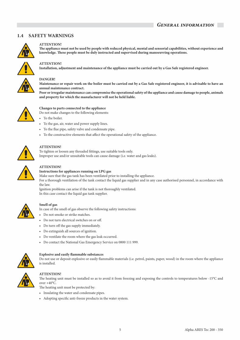
3.8 ADDITIoNAL SAfETy, pRoTECTIoN AND CoNTRoL DEvICES
Regulations regarding additional safety devices: closely consult the legislative regulations and safety provisions in force in the country of installation of the appliance. Use the gas safety and cut-off valves suitable for application and compliant with provisions in force. The boiler is not supplied with an expansion vessel for the system. It is mandatory to install a closed expansion vessel to guarantee correct boiler operation. The expansion vessel must be compliant with standard requirements in force. The size of the expansion vessel depends on the data for the central heating system. Install a vessel with a capacity, determined by an authorised designer.
Safety devices.1 Gas cut-off valve: this has the function of directly cutting-off the
gas supply if the limit value of the water temperature is reached. The detection element must be installed as close as possible to the boiler flow pipe at a distance of < 500 mm, and must not have an isolation valve installed between it and the boiler. Not supplied by Alpha.
2 Safety valve: this has the function of releasing the fluid contained in the boiler into the atmosphere when it reaches the maximum operating temperature for any reason. Not supplied by Alpha.
2a visible tundish. Not supplied by Alpha.Install a discharge pipe from the safety valve via a tundish, to a drain that can be visually controlled. The pipe material must be of copper or steel and be at least the same diameter of the safety valve throughout its length.Install a safety valve, on the flow pipe, sized for boiler capacity, within 0.5 m of the boiler, and in compliance with regulations in force.
ATTENTIoN!Do not install any type of isolation device between the boiler and the safety valve.
Attention!The manufacturer will not be held liable in the case of failure to observe this precaution, where any work on the safety valve may cause damage to people, animals and property.
protection devices.10 Safety thermostat: this is designed to stop the boiler if the safety
thermostat installed on the boiler fails to operate correctly. It must have an IMMOVABLE calibration of < 100°C.
15 Minimum pressure switch: this is designed to stop the boiler if the minimum operating pressure drops (can be calibrated between 0.5 - 1.7 bar). It must be manually reset.
16 Extra socket 1".18 Safety pressure switch: this is designed to stop the boiler if the
maximum operating pressure is reached (can be calibrated between 1 - 5 bar).
Control devices.13 (pressure gauge - not supplied by Alpha) with (12) damper pipe
and (11) pressure gauge valve: it indicates the current pressure in the boiler, it must be graduated in 'bar', its full scale must match the maximum operating pressure and be equipped with a three-way valve with an attachment for the control pressure gauge.
14 Thermometer: this indicates the current temperature of the water contained in the boiler, it must be graduated in centigrade with a full scale of no more than 120°C.
17 Spare sockets: approved for the inclusion of control devices.19 1¼" stub pipes: for the inclusion of safety valves.20 flow switch: this is designed to stop the boiler in case of low flow
inside the primary circuit.3 Approved expansion vessel: this absorbs the increase in volume
of water in the system following an increase in temperature. Not supplied by Alpha.
8 y strainer.7 Modulating pump (Not included in the kit).5 hydraulic separator (Not included in the kit).4 Automatic air vent. Not supplied by Alpha.6 Drain cock. Not supplied by Alpha.

21
Instructions for the installer
Alpha ARES Tec 200 - 350
BCM
1
BCM
11121415
18
10
13
171916
22a 4
6
1a
3
20
5
7
8
Connect to return
3.9 hyDRAuLIC SEpARAToR
To ensure good operation it is necessary to use a hydraulic separator that guarantees:• Separation and collection of impurities in the circuits.• Optimal removal of air from the system.• Hydraulic decoupling between the two hydraulic circulation rings.• Balancing the circuits.
F = 100 mm ( 4") nominal diameterR = 100 mm (4") nominal diameter
hydraulic system filter50 mm (2") nominal diameter
3.10 hyDRAuLIC SySTEM fILTER
It is advisable to install a Y type strainer in the boiler return pipe. This filter will protect the boiler from sediments coming from the heating system.
Recommended installation.
F
F
R
R
PrimaryBoilerCircuit
SecondarySystemCircuit

22
Instructions for the installer
Alpha ARES Tec 200 - 350
3.11 DETERMINING ThE pRIMARy CIRCuIT puMp oR BoILER puMp
Alpha provides a series of primary rings complete with an accurately sized pump, if alternative solutions are being used, the boiler pump must have a head that is capable of ensuring the flow rates represented in the 'Water side head losses' graph.
The table below roughly indicates the flow rates of the pump based on the ΔT of the primary circuit if the installation is equipped with a hydraulic separator.
The pumps must be sized by the installer or designer based on the data for the boiler and system.The resistance curve on the water side of the boiler is represented in the table provided below. The pump is not an integral part of the boiler. It is advisable to choose a pump with a flow rate and head of approximately 2/3 of its typical curve.
EXAMpLE:for a ΔT 20 k, of an ARES Tec 250 the maximum required flow rate is 10514 l/h.from the head loss graph it is possible to deduce that the pump must ensure a head of at least 1.6 m/h2o.
3.12 vALvES
It is advisable to install isolation valves on the flow and return pipes of the system to allow the boiler to be disconnect or drained without draining the entire system.
ATTENTIoN! NEvER CuT off SAfETy DEvICES fRoM ThE BoILER, such as the safety valve and expansion vessel.
Power in kW 200 250 300 350Maximum flow rate in l/h (ΔT = 15 k) 11192 14018 16856 19712
Nominal requested flow rate in l/h (ΔT = 20 k) 8394 10514 12642 14784
Secondary circuits
NoTE: It is advisable to always use the hydraulic separator between the boiler circuit and the system.
0
0.40.2
0.60.8
1
1.41.2
1.61.8
2
2.42.2
2.62.8
3
3.43.2
3.63.8
4
4.44.2
4.64.8
5
5.45.2
5.65.8
6
0 2000 4000 6000 8000 10000 12000 14000 16000 20000 22000 24000 2600018000
Flow rate (l/h)
350300250200
Hea
d lo
ss (m
/H2O
)

23
Instructions for the installer
Alpha ARES Tec 200 - 350
External covering kit for plate exchanger kit.
3.13 CoMpLETE opTIoNAL kITS
Safety kits including pump and plate exchanger. Safety kits including pump and hydraulic separator.
External covering kit for hydraulic separator.

24
Instructions for the installer
Alpha ARES Tec 200 - 350
3.14 CoNDENSATE DRAIN
The condensate drain pipe must be:• Built to avoid gaseous combustion products from leaking out into
the environment or the drain, by the use of a trap.• Sized and built to allow liquid discharge to runoff correctly,
preventing any leaks (gradient of 3%).• Installed to avoid the liquid contained in it from freezing, under the
envisioned operating conditions.• Can be easily inspected from the relative trap.• Mixed with household wastewater, for example, (washing machine
and dish washer drains etc.) with a mainly alkaline pH so as to form a buffer solution to send it into the sewers.
The condensate must not be left to stagnate in the combustion product drainage system (for this very reason the drain pipe must be set up at an inclination of at least 30 mm/m, running towards the drain) except for any liquid head, in the drain trap of the combustion product drain system (which must be filled after installation and at a minimum height with all of the fans operating at maximum speed of at least 25 mm) - see diagram below.
* Minimum safety trap enforced by regulation.
** Minimum head with boiler operating at maximum output.If you do not want to or are able to create a plinth, it is possible to install the boiler on the floor and set up the trap at a depth of 100 mm.
The condensate must not be allowed to drain into rain water gutters, given the risk of ice and degradation of materials normally used to build the rain pipes themselves.
The drain fitting must be visible.
Given the degree of acidity of the condensate (pH between 3 and 5) suitable plastic materials must be used to build the drain pipes.
The condensate drain pipe outlet is set up towards the connection side of the flue box manifold, removing the pre-cut section in the cover panel.
The recommended material for use must be PE (polyethylene) or PP (polypropylene).
Before starting the boiler for the first time, fill the trap through the fill point shown in the diagram below.
150
Plinth (100 mm min)25*
150** To condensate drain
Floor ofboiler room
The top of thecondensate pipemust not be higherthan the base of thecondensate tray
Trap �ll point

25
Instructions for the installer
Alpha ARES Tec 200 - 350
Ø21 mm
3.15 CoNNECTING ThE fLuE
Condensing boilers produce flue products at very low temperatures, generally below 84°C (approx). It is therefore necessary that the flue is impervious to the condensate produced and built with suitable corrosion-resistant materials.The connecting joints must be sealed and equipped with suitable gaskets to stop condensation from leaking out and air from getting in. In terms of flue section and height, it is necessary to refer to national and local regulations in force. Refer to regulations in force for sizing.In order to avoid the formation of ice during operation, the temperature of the inside wall at every point in the flue system, for its entire length, must not drop below 0°C.
The flue system must comply with local and national regulations. The flue system must be built using materials that are resistant to the combustion products, typically 316 certified stainless steel or plastic materials, such as pvDf (polyvinyldimethylfluoride) or ppS (simple translucent polypropylene) or other materials with the same features.
The supplier is excluded from any contractual and extra-contractual liability for damage caused by errors in installation and use due to failure to observe the instructions provided by the manufacturer.
Model Modules Flue spigot diameter200 4 150250 5 200300 6 200350 7 200
3.16 fLuE MANIfoLD CoNNECTIoN
To secure the flue exhaust manifold use the 6 nuts and washers contained in the bag.
A flue test point must be positioned on the first straight section, within 1 metre of the boiler.To install the test point (supplied), drill a 21 mm hole in the flue pipe, and fit the test point following the sequence shown below.

26
Instructions for the installer
Alpha ARES Tec 200 - 350
Example: ARES Tec 250Maximum flue flow rate = 408.6 Kg/hHeight of flue = 25 mDiameter = 250 mm
NoTE:The diagram above provides rough values only. The flue must be designed by a qualified professional in compliance with legislation and technical standard in force.
Table of maximum flue flow rate Model Max flue flow rate (kg/h)
200 326.9250 408.6300 490.3350 572.0
fLuE SIZING ACCoRDING To DIN 4705
2
No
min
al h
eat
inp
ut
(kW
)
Nom
inal
ther
mal
�ow
rate
(kW
) with
CO
con
tent
at 1
0%2
d125a
d400a
d315a
d250a
d200a
d160a
d110a
d75a
6
789
10
12
14161820
30
40
50
60
708090
100
120
140
160180200
300
400
500
600
700
800900
1000
1200
1400
4.4
5.96.67.4
8
9
1012
22
30
37
44
52596674
89
104
119133148
222
296
370
444
519
593668741
889
1037
3.4
3.94.45.05.6
7
89
11
17
22
28
34
39445056
67
78
89100111
167
222
277
333
389
445
555
667
778
0.001
0.0020.0030.0040.005
0.006
0.0070.0080.0090.010
0.015
0.020
0.030
0.0350.040
0.050
0.060
0.070
0.0800.0900.100
0.150
0.200
0.250
0.300
0.350
0.400
0.500
0.600
50.700
9.0
10.812.014.4
22
25293236
54
72
90
108
126144
180
216
252
288324360
540
720
900
1080
1260
1440
1800
2160
2520
6
789
10
12
14161820
30
40
50
60
708090
100
120
140
160180200
300
400
500
600
700
800900
1000
1200
1400
8%6%kg/skg/h 10%10 15 20 25 30
5 10 15 20 25 30
Available pressureFlue �ow rate
Flue temperature40 Pa40°C
408 250
CO content
0.025
18
101513
501
27
Instructions for the installer
Alpha ARES Tec 200 - 350
123Y2
4567
Y3
123
Jp1123
Y44
DL1 DL2 DL3
1 2 3Y14 5 6
A1
SW1
GCI
eBU
S-
eBU
S+
+24
V
0 1
23
456
78
9
1 2 3 4 5 6 7 8 9 10
IIA1A2A3A4A5A6
NL1L1’
M
T1T2
12A7
T3T4
VI12345
A8A9A10A11 IV
4
M2 13
n
1 2 3 4IX
LHBUS
1 2 3III
IMP0-10V
F17F15
31 FBR
1 2VIII
PT1000
F14F13
1 2V
SPF
F12F11
VFAFKF/SPFVF
F9F8F6F5F3F2F1
FBR
eBUSFA
0-10V
1 2 IVII
678910 12345
121 NL1L1
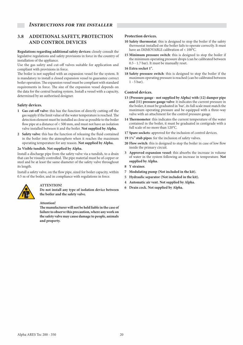
3.17 ELECTRICAL CoNNECTIoNS
General recommendationsElectrical safety of the appliance is only ensured when it is correctly connected to an efficient earthing system as specified by current safety standards. Gas, water and heating system pipes are not suitable in any way whatsoever as earthing connections.
It is necessary to check this fundamental safety requirement. In case of doubt, have an accurate inspection of the electrical system carried out by professionally qualified personnel, as the manufacturer is not responsible for any damage caused by the lack of a earthing connection in the system.
TGC Terminal board (rear view) GCI Terminal board (rear view)
Have professionally qualified personnel make sure the electrical system is suitable for the maximum power used by the appliance, as stated on the data plate, making sure in particular that the section of the system wiring is suitable for the power used by the appliance.
For the main power supply to the appliance, never use adapters, multiple sockets and/or extension leads.
Components involving the use of electrical power require some fundamental rules to be observed such as: • Do not touch the appliance with wet and/or moist parts of the body
and/or barefoot.• Do not pull the electric cables.• The appliance may not be used by children or unskilled individuals.
24 V
230 V
Mains connection(view A)
FL
GCITGC
Neutral connection (N)rear side
FL - Flow switch connections
View A
28
Instructions for the installer
Alpha ARES Tec 200 - 350
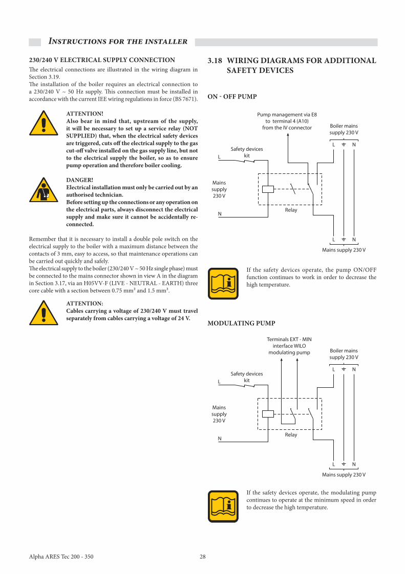
230/240 v ELECTRICAL SuppLy CoNNECTIoNThe electrical connections are illustrated in the wiring diagram in Section 3.19.The installation of the boiler requires an electrical connection to a 230/240 V ~ 50 Hz supply. This connection must be installed in accordance with the current IEE wiring regulations in force (BS 7671).
ATTENTIoN!Also bear in mind that, upstream of the supply, it will be necessary to set up a service relay (NoT SuppLIED) that, when the electrical safety devices are triggered, cuts off the electrical supply to the gas cut-off valve installed on the gas supply line, but not to the electrical supply the boiler, so as to ensure pump operation and therefore boiler cooling.
DANGER!Electrical installation must only be carried out by an authorised technician.Before setting up the connections or any operation on the electrical parts, always disconnect the electrical supply and make sure it cannot be accidentally re-connected.
Remember that it is necessary to install a double pole switch on the electrical supply to the boiler with a maximum distance between the contacts of 3 mm, easy to access, so that maintenance operations can be carried out quickly and safely.The electrical supply to the boiler (230/240 V ~ 50 Hz single phase) must be connected to the mains connector shown in view A in the diagram in Section 3.17, via an H05VV-F (LIVE - NEUTRAL - EARTH) three core cable with a section between 0.75 mm² and 1.5 mm².
ATTENTIoN:Cables carrying a voltage of 230/240 v must travel separately from cables carrying a voltage of 24 v.
3.18 wIRING DIAGRAMS foR ADDITIoNAL SAfETy DEvICES
oN - off puMp
MoDuLATING puMp
If the safety devices operate, the pump ON/OFF function continues to work in order to decrease the high temperature.
If the safety devices operate, the modulating pump continues to operate at the minimum speed in order to decrease the high temperature.
Pump management via E8
to terminal 4 (A10)
from the IV connector
Safety devices
kit
Relay
Mains supply 230 V
Boiler mains
supply 230 V
L
N
Mains
supply
230 V
L N
L N
Terminals EXT - MIN
interface WILO
modulating pump
Safety devices
kit
Relay
Mains supply 230 V
Boiler mains
supply 230 V
L
N
Mains
supply
230 V
L N
L N

29
Instructions for the installer
Alpha ARES Tec 200 - 350
L1
N
N
230
V
Relay
Safety group
L1
L1
NE
Gas valve
Mains supply230/240 V ~ 50 Hz
General electricalcontrol panel
Press. max
Press. min
C NC NOCC NCThermostat
Flow switchFL
Terminal block aboveboiler circuit board
1 2 3 4 5 6 7 8 9 10 1 2 3 4IX
1 2 3IIIF17F15
1 2VIIIF14F13
1 2VF12F11F9F8F6F5F3F2F1
1 2 IVII II A1 A2 A3 A4 A5 A6
1 2A7VI
1 2 3 4 5A8 A9 A10 A11IV
6 7 8 9 101 2 3 4 5
1 2 1N L1 L1
TGC
Externalsensor
123Y2
4567Jp1
Y3
123
123Y4
4
GCI
NE
L1
Modulating pumpinterface boardIF-EXT.Min. 0 - 10 V
L1
N
N
230
V
Relay
Safety group
L1On/O�N
L1
L1
NE
Gas valve
Mains supply230/240 V ~ 50 Hz
General electricalcontrol panel
Press. max
Press. min
C NC NOCC NCThermostat
Pump
Flow switchFL
Terminal block aboveboiler circuit board
123Y2
4567
Y3
123
Jp 1123
Y44
GCI
1 2 3 4 5 6 7 8 9 10 1 2 3 4IX
1 2 3IIIF17F15
1 2VIIIF14F13
1 2VF12F11F9F8F6F5F3F2F1
1 2 IVII II A1 A2 A3 A4 A5 A6
1 2A7VI
1 2 3 4 5A8 A9 A10 A11IV
6 7 8 9 101 2 3 4 5
1 2 1N L1 L1
TGC
Externalsensor
3.19 CoNNECTIoN DIAGRAM
power supply, gas valve, safety group, modulating pump, external sensor, and flow switch.
If the safety devices operate, the On/Off pump continues operating to lower the high temperature.
If the safety devices operate, the modulat ing pump reduces to the minimum s p e e d a n d c o nt i nu e s operating to lower the high temperature.
NOT SUPPLIED
NOT SUPPLIED
power supply, gas valve, safety group, on/off pump, external sensor and flow switch.

30
Instructions for the installer
Alpha ARES Tec 200 - 350
Gas valve
Press. max
Press. min
C NCNO CC NCThermostat
BCM
19
123Y2
4567
Y3
123
Jp1123
Y44
GCI
L1
NE
LN
L1NE
L1
N
L1
N
230
V
General electricalcontrol panel
Flow switchFL
Terminal block aboveboiler circuit board
Mains supply230/240 V ~ 50 Hz
1 2 3 4 5 6 7 8 9 10 1 2 3 4IX
1 2 3IIIF17F15
1 2VIIIF14F13
1 2VF12F11F9F8F6F5F3F2F1
1 2 IVII II A1 A2 A3 A4 A5 A6
1 2A7VI
1 2 3 4 5A8 A9 A10 A11IV
6 7 8 9 101 2 3 4 5
1 2 1N L1 L1
TGC
Externalsensor
Relay
Safety group
Safety group
Interface board IF-EXT. Min. 0 - 10 V
1 2 3 4 5 6 7 8 9 10 1 2 3 4IX
1 2 3IIIF17F15
1 2VIIIF14F13
1 2VF12F11F9F8F6F5F3F2F1
1 2 IVII
TGC
On/Off contact
Safety group connection (supplied with modulating pump).
NOT SUPPLIED
NO T
SUPPLIED
on/off thermostat connection.
1 2 3 4 5 6 7 8 9 10 1 2 3 4IX
1 2 3IIIF17F15
1 2VIIIF14F13
1 2VF12F11F9F8F6F5F3F2F1
1 2 IVII II A1 A2 A3 A4 A5 A6
1 2A7VI
1 2 3 4 5A8 A9 A10 A11IV
6 7 8 9 101 2 3 4 5
1 2 1N L1 L1
E8
10
2 3
24
18 6
12
On/O�
10
2 3
24
18 6
12
On/O�
Zone 1 Zone 2
TGC

31
Instructions for the installer
Alpha ARES Tec 200 - 350
1 2 3 4 5 6 7 8 9 10 1 2 3 4IX
1 2 3IIIF17F15
1 2VIIIF14F13
1 2VF12F11F9F8F6F5F3F2F1
1 2 IVII II A1 A2 A3 A4 A5 A6
1 2A7VI
1 2 3 4 5A8 A9 A10 A11IV
6 7 8 9 101 2 3 4 5
1 2 1N L1 L1
E8
1
2
Zone 1
1
2
Zone 2
TGC
1 2 3 4 5 6 7 8 9 10 1 2 3 4IX
1 2 3IIIF17F15
1 2VIIIF14F13
1 2VF12F11F9F8F6F5F3F2F1
1 2 IVII II A1 A2 A3 A4 A5 A6
1 2A7VI
1 2 3 4 5A8 A9 A10 A11IV
6 7 8 9 101 2 3 4 5
1 2 1N L1 L1
E8
10
2 3
24
18 6
12
10
2 3
24
18 6
12
Zone 1 Zone 2
TGC
NOT SUPPLIED
NOT SUPPLIED
Modulating room thermostats connection.
Modulating zone manager connection.

32
Instructions for the installer
Alpha ARES Tec 200 - 350
3.20 wIRING DIAGRAM
Colour CodeBr.......... BrownBl .......... BlueBk ......... BlackGy ........ GreyG/Y....... Green/Yellow
L Bl ....... Light BlueOr ......... OrangePk ......... PinkR ........... RedW .......... White
SMG
3rd - 7th Module
TGC control unit
1 2 3 4 5 6 7 8 9 10
IIA2A3A4A5A6
NL1L1'T1T2
12
A7
T3T4
FA
VI
12345
A8A9A10A11 IV
M M
n
2 3 4IX
LHBUS
2 3III
IMP0 - 10VLicht
F17F15
1 1F9 F12 F14F13
31FBR
1 2VIII
Pt1000
1 2V
SPF
1
F11
AFVF VFKF/SPF
F8F6F5F3F2F1
FBR
eBUS0 - 10V
1 2I
78910 123456
121 NL1L1'
M2
Bl
123
Y2
4567
Y3
123
Jp1
123
Y4
4
1 2 4 6
A1
SW1
GCI
+ 2
4V
PR
IG
II
I
O11a
1a1a
11
SE8/BCM
1b
TLTL 1 TL 2 - 7
1st Module
E.RIL 1
SR 1
SRR
SR
E.RIL 2 - 7
2nd - 7th Module
PGTRA.ACC 2 - 7
SL
PF
(3)(1)
( )
01
2 3 45
6
789
0 1
23
45
6
78
9
IG(IG2)
5L 4L
1N
2N
F10A
F6.3A
N L1
KF
Bl
Bl
Bl
Bl
Bl
Bl
Bl
Bl
BkBr
Br
Br
Br
Br
BrBr
Br Bl
Bl
Br
Br
Br
Br
Bl
Bl
Bk
Bk
BkBk
Bk
R
Or
G/Y
L BlL Bl L Bl
L Bl
Br
W
W
WW
1 (NC)
3 (C)
W
W
R
R
W
Y1
W
W
R
Bk
Pk Gy
W
Bl
G/YG/Y
12
A7
A6
A8
Y1
A1
0
A1
1
A2
A4
A1
6 5
4 3
2 1
3 2
14
32
1Gy
Pk
G/Y
35 IV VI
12
1 3
11
21 21 2 1
3 412 11
2
VF SPF KF VIIIVAF1 2 3 1 2 3 H L
3 5 2
1 9
10
eB
US
+
eB
US
-
0 -
10
V
( -
)
( -
)
( +
) RBr
BkMo
db
us
-A
Mo
db
us
-B
Re
lea
se
Bo
ard
inse
rtio
n
Ala
rmsi
gn
al
BlBl
Bl
ROD ROD(FS 1)(FS 1)
GN
D1
GN
D5
BlBr
G/Y
G/Y
Br
L Bl
Br
L Bl
L Bl L Bl
W
Bk Br
W
BlBr
G/Y
W
G/Y
W
W
Br
OrOr
R
E.ACC 1
+ 2
4V
eB
US
-
eB
US
+
VG 1
SR 2 - 7
Bk
Br
R
11 1
22 2
34
56
12
34
123 123
A6
A8
Y1
12
34
56
12
34
A7
21
Br Bl
Bl
Br
G/Y
G/Y
Bl
Br
GN
D1
GN
D5
A2
A4
A1
A38
7 6
5 4
3 2
1
A38
7 6
5 4
3 2
1
6 5
4 3
2 1
3 2
14
3 2
1
A1
0
A1
1
1 12 23 3GY
PkPkGY
R
GY
01
2 3 45
6
789
PLC/
BMS
Only on 1st
module board
3rd - 7th Module
Mains supply
230/240 V ~ 50 Hz
A
B
VT NL
1
J61J3
1J4
1J3
1J2
1
1 J1
(IG1)
Neutralconnections
VM 1VM 2 - 7
OptionalVG 2 - 7
E.ACC 2 - 7FL optional
2nd module only
Only on the2nd module
TRA.ACC 1
Connectionwith BCM
Bl (Tacho)
Bk (-)
Br (PWM)
Or (+)
Br (L1)
L Bl (N)
G/Y
Ali
m.
23
0V
RIL
./R
EG
.
14
25
L1
PE
N
Bl (Tacho)
Bk (-)
Br (PWM)
Or (+)
Br (L1)
L Bl (N)
G/Y
Ali
m.
23
0V
RIL
./R
EG
.
14
25
L1
PE
N
Ma
nif
old
cir
cuit
Pu
mp
co
ntr
ol
Remote eBUS(external cascade manager)
External sensoror emergency
set point input
Modulating pumpcontrol
DL1 DL2 DL3
*
Optional to replace link
2
Br
TLGC1
11b 1a
LTLGBl
Bk
R
J3
Link
( )
4
5
6
7
1
2
2
3
2 - 3
2 - 3 / 4 - 5
2 - 3 / 4 - 5
2 - 3 / 4 - 5 / 6 - 7
No. ofmodules
No. offilters
Place betweenmodules Nos.
Fan speed filter detail
Filter
Br Br
R R
Br
Bl
G/Y
Bl Bl
Br
N
VM (A)5
ST2
1234
Br BlG/Y
L1
1 2 3
VM (A)5
ST2
1234
Br BlG/Y
L1
1 2 3
Ext sensoropen
100 K4722
Short circuit
ΩKK
10 K
ΩΩΩ
Set point82°C7160493827
°C°C°C°C°C
(*)

33
Instructions for the installer
Alpha ARES Tec 200 - 350
SMG
3rd - 7th Module
TGC control unit
1 2 3 4 5 6 7 8 9 10
IIA2A3A4A5A6
NL1L1'T1T2
12
A7
T3T4
FA
VI
12345
A8A9A10A11 IV
M M
n
2 3 4IX
LHBUS
2 3III
IMP0 - 10VLicht
F17F15
1 1F9 F12 F14F13
31FBR
1 2VIII
Pt1000
1 2V
SPF
1
F11
AFVF VFKF/SPF
F8F6F5F3F2F1
FBR
eBUS0 - 10V
1 2I
78910 123456
121 NL1L1'
M2
Bl
123
Y2
4567
Y3
123
Jp1
123
Y4
4
1 2 4 6
A1
SW1
GCI
+ 2
4V
PR
IG
II
I
O11a
1a1a
11
SE8/BCM
1b
TLTL 1 TL 2 - 7
1st Module
E.RIL 1
SR 1
SRR
SR
E.RIL 2 - 7
2nd - 7th Module
PGTRA.ACC 2 - 7
SL
PF
(3)(1)
( )
01
2 3 45
6
789
0 1
23
45
6
78
9
IG(IG2)
5L 4L
1N
2N
F10A
F6.3A
N L1
KF
Bl
Bl
Bl
Bl
Bl
Bl
Bl
Bl
BkBr
Br
Br
Br
Br
BrBr
Br Bl
Bl
Br
Br
Br
Br
Bl
Bl
Bk
Bk
BkBk
Bk
R
Or
G/Y
L BlL Bl L Bl
L Bl
Br
W
W
WW
1 (NC)
3 (C)
W
W
R
R
W
Y1
W
W
R
Bk
Pk Gy
W
Bl
G/YG/Y
12
A7
A6
A8
Y1
A1
0
A1
1
A2
A4
A1
6 5
4 3
2 1
3 2
14
32
1
Gy
Pk
G/Y
35 IV VI
12
1 3
11
21 21 2 1
3 412 11
2
VF SPF KF VIIIVAF1 2 3 1 2 3 H L
3 5 2
1 9
10
eB
US
+
eB
US
-
0 -
10
V
( -
)
( -
)
( +
) RBr
BkMo
db
us
-A
Mo
db
us
-B
Re
lea
se
Bo
ard
inse
rtio
n
Ala
rmsi
gn
al
BlBl
Bl
ROD ROD(FS 1)(FS 1)
GN
D1
GN
D5
BlBr
G/Y
G/Y
Br
L Bl
Br
L Bl
L Bl L Bl
W
Bk Br
W
BlBr
G/Y
W
G/Y
W
W
Br
OrOr
R
E.ACC 1
+ 2
4V
eB
US
-
eB
US
+
VG 1
SR 2 - 7
Bk
Br
R
11 1
22 2
34
56
12
34
123 123
A6
A8
Y1
12
34
56
12
34
A7
21
Br Bl
Bl
Br
G/Y
G/Y
Bl
Br
GN
D1
GN
D5
A2
A4
A1
A38
7 6
5 4
3 2
1
A38
7 6
5 4
3 2
1
6 5
4 3
2 1
3 2
14
3 2
1
A1
0
A1
1
1 12 23 3
GYPkPk
GY
R
GY
01
2 3 45
6
789
PLC/
BMS
Only on 1st
module board
3rd - 7th Module
Mains supply
230/240 V ~ 50 Hz
A
B
VT NL
1
J61J3
1J4
1J3
1J2
1
1 J1
(IG1)
Neutralconnections
VM 1VM 2 - 7
OptionalVG 2 - 7
E.ACC 2 - 7FL optional
2nd module only
Only on the2nd module
TRA.ACC 1
Connectionwith BCM
Bl (Tacho)
Bk (-)
Br (PWM)
Or (+)
Br (L1)
L Bl (N)
G/Y
Ali
m.
23
0V
RIL
./R
EG
.
14
25
L1
PE
N
Bl (Tacho)
Bk (-)
Br (PWM)
Or (+)
Br (L1)
L Bl (N)
G/Y
Ali
m.
23
0V
RIL
./R
EG
.
14
25
L1
PE
N
Ma
nif
old
cir
cuit
Pu
mp
co
ntr
ol
Remote eBUS(external cascade manager)
External sensoror emergency
set point input
Modulating pumpcontrol
DL1 DL2 DL3
*
Optional to replace link
2
Br
TLGC1
11b 1a
LTLGBl
Bk
R
J3
Link
( )
4
5
6
7
1
2
2
3
2 - 3
2 - 3 / 4 - 5
2 - 3 / 4 - 5
2 - 3 / 4 - 5 / 6 - 7
No. ofmodules
No. offilters
Place betweenmodules Nos.
Fan speed filter detail
Filter
Br Br
R R
Br
Bl
G/Y
Bl Bl
Br
N
VM (A)5
ST2
1234
Br BlG/Y
L1
1 2 3
VM (A)5
ST2
1234
Br BlG/Y
L1
1 2 3
Key:E.ACC 1 - 7 ....... Ignition electrodeE.RIL 1 - 7 ......... Flame sensing electrodeFL .................... Blade flow switch (optional)IG .................... Main switchKF .................... TGC global flow sensorLTLG ................. Limit thermostat lamp (optional)PF .................... Flue pressure switchPG .................... Gas pressure switchSL .................... Condensate level sensorSMG ................. GCI flow sensorSR .................... Flow sensor SR 1 - 7 ............. Local flow sensorSRR ................... Heating return sensorTL .................... Overheat thermostat TL 1 - 7 ............. Local overheat thermostat TLG ................... General limit thermostat (optional) VG 1 - 7 ............ Gas valve TRA.ACC 1 - 7 .. Ignition transformer VM 1 - 7 ............ Modulating fan
01
2 3 45
6
789
01
2 3 45
6
789
01
2 3 45
6
789
01
2 3 45
6
789
01
2 3 45
6
789
01
2 3 45
6
789
01
2 3 45
6
789
Module 1(setting 0)
Module 4(setting 3)
Module 3(setting 2)
Module 2(setting 1)
Module 5(setting 4)
Module 6(setting 5)
Module 7(setting 6)PCB module address
selector setting oneach module

34
Instructions for the installer
Alpha ARES Tec 200 - 350
3.21 CoNNECTIoNS AND MANAGEMENT DIAGRAM
On the rear of the control panel, there are two terminal blocks: one for the network connections, the other for the low voltage connections. The main controls required for boiler management and some parts of the heating control unit must be connected to the terminal blocks.
Identification of terminal block for network connections.
12345678910
II A1 A2 A3 A4 A5 A6
N L1 L1 ’
M
T1 T2
1 2A7
T3 T4
VI1 2 3 4 5A8 A9 A10 A11IV
4
M21 3
n
1234IX
L HBUS
123 III
IMP 0-10 V
F17 F15
3 1FBR
12 VIII
PT1000
F14 F1312 V
SPF
F1 2 F 11
VF AF KF / SPF VF
F9 F8 F6 F5 F3 F2 F1
FBR
eBUSFA
0-10 V
12IVII
6 7 8 9 101 2 3 4 5
1 2 1Networkterminal block
Low voltageterminal block
Mains supply230/240 V ~ 50 Hz
BkBl Br
PkGy
From the GCI
Heatingsensor
1
Heatingsensor
2
Externalsensor
Storagetank
sensor
Global�ow
sensor
N L1 L1’
Colour CodeBr.......... BrownBl .......... BlueBk ......... BlackGy ........ GreyPk ......... Pink
12
A7
T3T4
VI
Terminal VI VI
12
34
5A
8A
9A
10A
11IV
4
M2
13
n
Terminal IV IV
: Mixing valve heating circuit 1 OPEN /multifunction relay: Mixing valve heating circuit 1 CLOSED/multifunction relay
Multifunction relayMultifunction relay
21
43
Terminal II
IIA
1A
2A
3A
4A
5A
6
NL1
L1’
M
T1
T2
67
89
101
23
45
NL1
L11
21
II
N: Neutral network cableL1 : Boiler network supplyL1’: Relay network supply
: Heating pump circuit 1: Heating pump circuit 2: Storage tank load pump
: Mixing valve heating circuit 2 OPEN: Mixing valve heating circuit 2 CLOSED

35
Instructions for the installer
Alpha ARES Tec 200 - 350
123Y2
4567
Y3
123
Jp1123
Y44
DL1 DL2 DL3
1 2 3Y14 5 6
A1
SW1
BCM
eBU
S-
eBU
S+
+24
V
0 1
23
456
78
9
Identification of terminal block for low voltage connections.
GCI terminal board description.
Terminal VII VII
eBU
SFA 0-10
V 12
VII Pin 1: eBUS (F A) or 0 - 10 V output
Pin 2: (earth BUS / 0 - 10 V)
To be connected to the GCI
Terminal I I
12
34
56
78
910A
FK
F/ S
PFV
F
F9F8
F6F5
F3F2
F1
FBR
I
Pin 1: Bu�er under sensorPin 2: Sensor centre bu�er / Remote sensor heating circuit 1 (room sensor)Pin 3: Bu�er over sensor / Remote sensor heating circuit 1 (nom. value)
Pin 4: Flow sensor ground heating circuit 2 / remote ground circuit 1Pin 5: Flow sensor heating circuit 2Pin 6: Storage tank sensorPin 7: Global �ow sensor groundPin 8: Global �ow sensorPin 9: External sensorPin 10: External sensor ground / �ow sensor ground heating circuit 1
VFVF
SPFSPFKFAFAF
12
V
SPF
F12
F11
VF
Terminal V V
Pin 1: Flow sensor heating circuit 1 / multifunction sensor 1Pin 2: Storage tank sensor (lower) / multifunction sensor 2
VFSPF
12
VIII
PT10
00
F14
F13
Terminal VIII
F13F14
Pin 1: CM2 sensor /solar sensor 2 /multifunction relay sensor 3Pin 2: Solar sensor 1 / multifunction relay sensor 4
PT 1000 sensor
Terminal III III
12
3II
I
IMP
0-10
V
F17
F15
31
FBR
Pin 1: 0 - 10 V input (to be enabled)Pin 2: Earth
F15
F17
12
34
IX
LH
BUS
Terminal IX IX
H CAN Bus Pin 1 = H (data)CAN Bus Pin 2 = L (data)CAN Bus Pin 3 = - (Earth)CAN Bus Pin 4 = + (12 V power supply)
L-+
To be connected to remote control devices1
23Y4
4
Alarm signal
Pump control manifold circuit
Modulating pump control
12
3
Y2 4
56
7
0-10 V
Modbus - BModbus - A
PLC /BMS
( - )
( - )( + )
Remote eBUS(external cascade manager)
Emergency set pointconnect resistance according to the table (*)
Ext sensoropen
100 K4722
Short circuit
ΩKK
10 K
ΩΩΩ
Set point82°C7160493827
°C°C°C°C°C
(*)

36
Instructions for the installer
Alpha ARES Tec 200 - 350
Heating circuit 2 Mainssupply
Recirc.DHW
VF
Heating circuit 1
VF
SPF
21
n
4
VF
VF
VF
HydraulicseparatorFilter
Safety group
AF
External sensor
3
Flow
Return
Storagecylinder
Manifoldpump
Filter
Safety group
AF
External sensor
Heating circuit 1
VF
1
VF
VF
Hydraulic separator
Manifoldpump
3
Flow
Return
3.22 EXAMpLES of INSTALLATIoN (functional diagram and description of connections)
Boiler connected to a direct zone.
Boiler connected to one mixed zone and one direct zone + supply of domestic hot water.
(9-10) External sensor (6-7) Storage tank sensor
(4) Pump heating circuit 1(5) Pump heating circuit 2(6) Storage tank pump
(5) Storage tank recirculation pump
(4-5) Flow sensor heating circuit 2
(1) Flow sensor heating circuit 1
(10) Flow sensor earth heating circuit 1
(1) Flow sensor heating circuit 1(10) Flow sensor earth heating circuit 1
(9-10) External sensor
(4) Pump heating circuit 1
(4) Manifold pump
(4) Manifold pump
(7) Mixing valve heating circuit 2 OPEN (8) Mixing valve heating circuit 2 CLOSED

37
Instructions for the installer
Alpha ARES Tec 200 - 350
VF VF
SPF
1 2
n
4
VFVF
VF
3
Heating circuit 2 Mainssupply
Recirc.DHWHeating circuit 1
HydraulicseparatorFilter
Safety group
AF
External sensor
Flow
Return
Storagecylinder
Manifoldpump
VF VF
SPF
1 2
n
4
VFVF
VF
3
Heating circuit 2 Mainssupply
Recirc.
DHWHeating circuit 1
HydraulicseparatorFilter
Safety group
AF
External sensor
Flow
Return
Storagecylinder
Manifoldpump
Boiler connected to two mixed zones + supply of domestic hot water.
(9-10) external sensor
(4-5) flow sensor heating circuit 2
(6-7) storage tank sensor
(4) Pump heating circuit 1(5) Pump heating circuit 2(6) Storage tank pump
(7) Mixing valve heating circuit 2 OPEN (8) Mixing valve heating circuit 2 CLOSED
Boiler connected to two direct zones + supply of domestic hot water.
(1) Mixing valve heating circuit 1 OPEN (2) Mixing valve heating circuit 1 CLOSED
(5) Storage tank recirculation pump
(5) Storage tank recirculation pump
(9-10) External sensor
(6-7) Storage tank sensor
(4) Pump heating circuit 1(5) Pump heating circuit 2(6) Storage tank pump
(4-5) Flow sensor heating circuit 2 (1) flow sensor heating circuit 1(10) flow sensor earth heating circuit 1
(1) flow sensor heating circuit 1(10) flow sensor ground heating circuit 1
(4) Manifold pump
(4) Manifold pump

38
Instructions for the installer
Alpha ARES Tec 200 - 350
Secondary system connection.
Connection section B (heating circuit 1)
M2Blue
Blue
Blue
Blue
Blue
Blue
Blue
230
V
Relay
General electricalcontrol panel
L1
N
B
9 10 1 2VF12F11F9F8
I
IIA1 A2 A3
1 2A8 A9
IV64 5
1 2
TGC
Heating circuit 2 Mainssupply
Recirc.DHWHeating circuit 1
Storagecylinder
Storagesensor
Storagepump
Recirculationpump
Flow sensorcircuit 1
CH pumpcircuit 1
Divertervalve 1
Flow sensorcircuit 2
CH pumpcircuit 2
Divertervalve 2
Opening
Closing
Connection section C (heating circuit 2)
M2Blue
Blue
Blue
Blue
Blue
Blue
Blue
C
L1
N
II
TGC
4 5F5I A1 A2 A3 A4 A5
6 7 84 5
1 2
230
V
Relay
General electricalcontrol panel
B Heating circuit 2 Mainssupply
Recirc.DHWHeating circuit 1
Storagecylinder
Storagesensor
Storagepump
Recirculationpump
Flow sensorcircuit 1
CH pumpcircuit 1
Divertervalve 1
Flow sensorcircuit 2
CH pumpcircuit 2
Divertervalve 2
Ope
ning
Clos
ing

39
Instructions for the installer
Alpha ARES Tec 200 - 350
Connections to solar systems require changing a number of setting parameters.Refer to the TGC controller manual - Expert field →Level SoLAR / Mf → Mf 4 fuNCTIoN = "23"
Connection section D (domestic hot water circuit)
M2Blue
Blue
Blue
Blue
Blue
Blue
Blue
IIA1 A2 A3
64 5
1 2
TGC6 7 8F8F6
I
DC
L1
N
230
V Relay
General electricalcontrol panel
B Heating circuit 2Mainssupply
Recirc.
DHWHeating circuit 1
Storagecylinder
Storagesensor
Storagepump
Recirculationpump
Flow sensorcircuit 1
CH pumpcircuit 1
Divertervalve 1
Flow sensorcircuit 2
CH pumpcircuit 2
Divertervalve 2
M2Blue
Blue
Blue
Blue
Blue
Blue
Blue
9 10 1 2 3IIIF17F15
1 2VIIIF14F13
1 2VF12F11F9
I
E
3 4 5A10 A11
IV
TGC
L1
N
230
V Relay
General electricalcontrol panel
Heating circuit 2 Mainssupply
DHWHeating circuit 1
Storagesensor
Storagepump
Flow sensorcircuit 1
CH pumpcircuit 1
Divertervalve 1
Flowsensor
circuit 2CH
pumpcircuit 2
Divertervalve 2
Solarcircuitpump
Pt 1000solar sensor
Storagesensor
Hydraulicseparator
Connection section E (solar panels)

40
Instructions for the installer
Alpha ARES Tec 200 - 350
Two ARES Tec connected in a set, managed by an external TGC cascade regulator.
For any other system applications not included in these instructions, contact the Alpha Helpline 0844 871 8764.* Consult the TGC controller manual supplied.
6 7 8 9 10F9F8F6
I
1 2 3 4IXTGC
1 2 3 4IX
123
Y24567 Jp1
GCI
GCI
19
19
Bus ID HS = _ _ _ _
Bus ID HS = 01
Position II
SW1
0 1
23
456
78
9
SW1
0 1
23
456
78
9
GCI
19
Safety group
LN
LN
TGC
123
Y24567 Jp1
GCI
TGC
1 2 3 4IX
Bus ID HS = 02
Position 0Position II
Bus ID HS = 01
Position 0Position II
Generalelectricalcontrolpanel
Flow switchFL
Terminal block onboiler circuit board
Mains supply230/240 V ~ 50 Hz
L1
NE
L1
N
L1NE
L1
N
230
V
Relay
L1
NE
L1
N
L1NE
L1
N
230
VRelay
Generalelectricalcontrolpanel
Flow switchFL
Terminal block onboiler circuit board
Mains supply230/240 V ~ 50 Hz
Safety group
Safety group
Safety groupGas valve
Press. max
Press. min
C NCNO CC NCThermostat
Gas valve
Press. max
Press. min
C NCNO CC NCThermostat
Interface boardIF - Ext. Min. 0-10V
Interface boardIF - Ext. Min. 0-10V
Externalsensor
KF-boiler global�ow sensor
Bus ID HS = 02
Position II
External cascade manager

41
Instructions for the installer
Alpha ARES Tec 200 - 350
3.23 SySTEM fILLING AND DRAINING
ATTENTIoN!Do not mix the heating water with antifreeze or anti-corrosion substances at incorrect concentrations! This may damage gaskets and cause noise to develop during operation. Alpha will not be held liable in case of damage caused to people, animals or property due to failure to observe the above.
Once all of the system connections have been made, it is possible to fill the circuit.
To fill the system install a filling loop and pressurisation unit to the system return pipe, in conjunction with a correctly sized expansion vessel/s. Never use a pressurisation unit to fill the system.
The boiler is fitted with a drain point, as shown in Section 2.2. This must never be used to drain the complete system, as dirt contained in the system may accumulate in the boiler, preventing smooth operation. Accordingly, the system must be equipped with its own drain point/s.
3.24 BoILER fRoST pRoTECTIoN
If the flow temperature (measured at the global flow sensor) should fall below 7°C the system pump starts operating.If the temperature drops any further (under 3°C), all modules ignite and run at the minimum output until the return temperature reaches 10°C.
This device protects the boiler only. In order to protect the system as well, it is necessary to add a suitable anti-freeze.
Note: The anti-freeze must be compatible with materials present in the entire system and suitable for use with aluminium alloys.

42
Instructions for the installer
Alpha ARES Tec 200 - 350
3
1
2
4
3.25 ChECk AND ADjuST ThE Co2 vALuES
ATTENTIoN!The instructions below are provided for the exclusive use of Gas Safe registered personnel.
All boilers leave the factory calibrated and approved, nevertheless, if the calibration conditions need to be changed it is necessary to re-calibrate the gas valve.
ATTENTIoN!Remove cap 2, attach the red cap 3 to the flue test point 1. Place the CO2 analysis probe 4 in the hole on the cap.Once the measurement has been made, take the cap out and use the relative cap 2 to seal the flue test point.
A) Adjustment at maximum output.• Remove the sealing cap for flue test point.• Place the analyser probe inside the flue test point.• Make burner 1 operate at maximum output, following the procedure
described at the end of this Section in 'Chimney sweep function' (100% CASC MANUAL).
• Make sure that the CO2 level falls within the values indicated in the 'NOZZLE - PRESSURES' table on the following page.
• It is possible to correct the value by turning adjusting screw 'A' using a suitable screwdriver.
CLOCKWISE to decrease it and ANTI-CLOCKWISE to increase it.
B) Adjustment at minimum output.• Make burner 1 operate at minimum output, following the procedure
described at the end of this Section in 'Chimney sweep function' (10% CASC MANUAL).
• Make sure that the CO2 level falls within the values indicated in the 'CO2 levels' table on the following page.
• It is possible to correct the value by turning adjusting screw 'B' using a 2 mm hex key.
CLOCKWISE to increase it and ANTI-CLOCKWISE to decrease it.
Gas valve maximum outputadjusting screw (slotted)
Gas valve minimum outputadjusting screw (2 mm hex key)
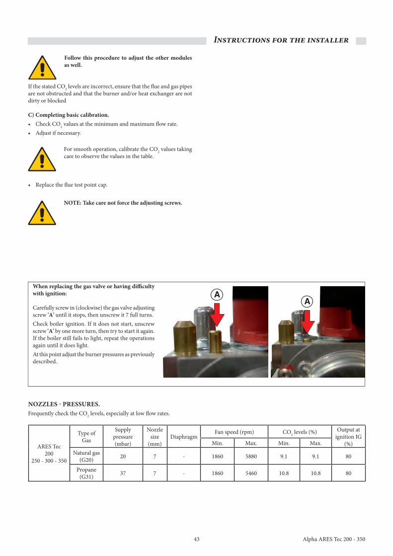
43
Instructions for the installer
Alpha ARES Tec 200 - 350
follow this procedure to adjust the other modules as well.
If the stated CO2 levels are incorrect, ensure that the flue and gas pipes are not obstructed and that the burner and/or heat exchanger are not dirty or blocked
C) Completing basic calibration.• Check CO2 values at the minimum and maximum flow rate.• Adjust if necessary.
For smooth operation, calibrate the CO2 values taking care to observe the values in the table.
• Replace the flue test point cap.
NoTE: Take care not force the adjusting screws.
when replacing the gas valve or having difficulty with ignition:
Carefully screw in (clockwise) the gas valve adjusting screw 'A' until it stops, then unscrew it 7 full turns.Check boiler ignition. If it does not start, unscrew screw 'A' by one more turn, then try to start it again. If the boiler still fails to light, repeat the operations again until it does light.At this point adjust the burner pressures as previously described.
NoZZLES - pRESSuRES.Frequently check the CO2 levels, especially at low flow rates.
ARES Tec200
250 - 300 - 350
Type of Gas
Supply pressure (mbar)
Nozzle size
(mm)Diaphragm
Fan speed (rpm) CO2 levels (%) Output at ignition IG
(%)Min. Max. Min. Max.Natural gas
(G20) 20 7 - 1860 5880 9.1 9.1 80
Propane (G31) 37 7 - 1860 5460 10.8 10.8 80

44
Instructions for the installer
Alpha ARES Tec 200 - 350
Chimney sweep function.
ATTENTIoN!The functions stay on for 30 minutes, after which time the set parameters are restored.
SERVICE
SW NO XXXX
CASC MANUAL
HS 01 - 00%
CODE No.
0 0 0 0 HS 01 - 00%
Before opening the TGC coverturn the navigation knob clockwise
to the chimney sweep symbol
Open the TGC cover
SETUP
Turnanti-clockwise
GENERAL
After2 seconds
DATE/TIME
Turnanti-clockwise
Appears
Press the buttonfor next level
Turnclockwise
Turnclockwise
RELAY TEST
SENSOR TESTTurn
clockwise
Press the buttonfor next level
5 times to enter theaccess code (’0’ 4 times) Appears
HS 02 - 00%
HS 03 - 00%
HS 04 - 00%
HS 05 - 00%
HS 06 - 00%
HS 07 - 00%
HS 08 - 00%
Bring percentagevalue to 10%
Press to enterand adjust
Con�rm
Con�rm
HS 01 - 00%
Bring percentagevalue to 10%
Bring percentagevalue to 100%
HS 01 - 100%
Equal to Q Max.
Equal to Q Min.
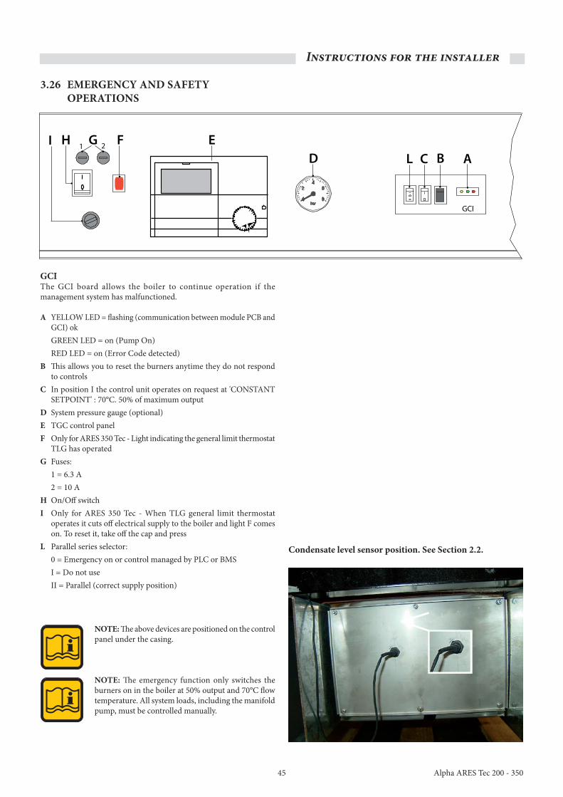
45
Instructions for the installer
Alpha ARES Tec 200 - 350
C B
GCI
DEFGHI
AL1 2
3.26 EMERGENCy AND SAfETy opERATIoNS
GCIThe GCI board allows the boiler to continue operation if the management system has malfunctioned.
A YELLOW LED = flashing (communication between module PCB and GCI) ok
GREEN LED = on (Pump On) RED LED = on (Error Code detected)B This allows you to reset the burners anytime they do not respond
to controlsC In position I the control unit operates on request at 'CONSTANT
SETPOINT' : 70°C. 50% of maximum outputD System pressure gauge (optional)E TGC control panelf Only for ARES 350 Tec - Light indicating the general limit thermostat
TLG has operatedG Fuses: 1 = 6.3 A 2 = 10 Ah On/Off switchI Only for ARES 350 Tec - When TLG general limit thermostat
operates it cuts off electrical supply to the boiler and light F comes on. To reset it, take off the cap and press
L Parallel series selector: 0 = Emergency on or control managed by PLC or BMS I = Do not use II = Parallel (correct supply position)
NoTE: The above devices are positioned on the control panel under the casing.
NoTE: The emergency function only switches the burners on in the boiler at 50% output and 70°C flow temperature. All system loads, including the manifold pump, must be controlled manually.
Condensate level sensor position. See Section 2.2.

46
Instructions for the installer
Alpha ARES Tec 200 - 350
3.27 fIRST IGNITIoN
preliminary checks.
first ignition must be carried out by a Gas Safe registered engineer. Alpha will not be held liable in case of damage caused to people, animals or property due to failure to observe the above.
DANGER!prior to commissioning the appliance fill the condensate trap through the filler hole and make sure the condensate is draining correctly.If the appliance is used with an empty condensate trap the danger of poisoning could exist.
Prior to commissioning the boiler it is advisable to make sure that:• Installation fulfils the standard specifications and requirements in
force for both the gas and electrical part.• The supply of combustion air and the evacuation of flue gases are
carried out correctly in accordance with standard specifications and requirements in force.
• The gas supply is sized for the boiler flow rate and is equipped with all of the safety and control devices required by regulations in force.
• The electrical supply for the boiler is 230/240 V ~ 50 Hz.• The system has been filled with water (pressure gauge 0.8/1.0 bar
with the pump off).• Any cut-off dampers in the system are open.• The required gas corresponds to the one used for boiler calibration.• The gas supply valve is open.• There are no gas leaks.• The external electrical supply is switched on.• The system safety valve on the boiler responds to operation and
discharges to a safe visible place.• The condensate trap is filled with water.• There are no water leaks.• Sufficient air supply for the boiler and minimum distances to carry
out any maintenance operations are fulfilled.
Switching the boiler on and off.To turn the boiler on and off read the manual for the TGC regulator.
Information for the Building manager.The individual in charge of the system must be instructed in the use and operation of the heating system, in particular:
• Supply the Building manager with the 'THE BUILDING INSTRUCTIONS FOR USE', as well as all other documents attached the appliance contained in the envelope in the packaging. The Building manager must keep this documentation safe so that it is available for future consultation.
• Inform the Building manager of the importance of ventilation and the flue system, highlighting how essential they are and how it is strictly forbidden to change them.
• Inform the Building manager of the requirement to check the system water pressure, as well as operations to restore it.
• Inform the Building manager on how to correctly regulate the temperature, control units/thermostats and radiators in order to save energy.
• Remember that it is compulsory to carry out regular maintenance on the system and measure combustion output (as per national law).
• If the appliance is sold or transferred to another owner or if the owner moves, leaving the appliance behind, always ensure the instructions supplied accompany the appliance so that it may be consulted by the new owner and/or installer.
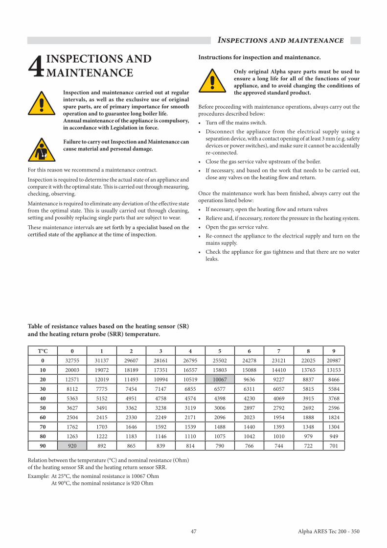
47
Inspections and maintenance
Alpha ARES Tec 200 - 350
Table of resistance values based on the heating sensor (SR) and the heating return probe (SRR) temperature.
T°C 0 1 2 3 4 5 6 7 8 90 32755 31137 29607 28161 26795 25502 24278 23121 22025 20987
10 20003 19072 18189 17351 16557 15803 15088 14410 13765 1315320 12571 12019 11493 10994 10519 10067 9636 9227 8837 846630 8112 7775 7454 7147 6855 6577 6311 6057 5815 558440 5363 5152 4951 4758 4574 4398 4230 4069 3915 376850 3627 3491 3362 3238 3119 3006 2897 2792 2692 259660 2504 2415 2330 2249 2171 2096 2023 1954 1888 182470 1762 1703 1646 1592 1539 1488 1440 1393 1348 130480 1263 1222 1183 1146 1110 1075 1042 1010 979 94990 920 892 865 839 814 790 766 744 722 701
Relation between the temperature (°C) and nominal resistance (Ohm) of the heating sensor SR and the heating return sensor SRR.Example: At 25°C, the nominal resistance is 10067 Ohm At 90°C, the nominal resistance is 920 Ohm
4 INSpECTIoNS AND MAINTENANCE
Inspection and maintenance carried out at regular intervals, as well as the exclusive use of original spare parts, are of primary importance for smooth operation and to guarantee long boiler life. Annual maintenance of the appliance is compulsory, in accordance with Legislation in force.
failure to carry out Inspection and Maintenance can cause material and personal damage.
For this reason we recommend a maintenance contract.
Inspection is required to determine the actual state of an appliance and compare it with the optimal state. This is carried out through measuring, checking, observing.
Maintenance is required to eliminate any deviation of the effective state from the optimal state. This is usually carried out through cleaning, setting and possibly replacing single parts that are subject to wear.
These maintenance intervals are set forth by a specialist based on the certified state of the appliance at the time of inspection.
Instructions for inspection and maintenance.
only original Alpha spare parts must be used to ensure a long life for all of the functions of your appliance, and to avoid changing the conditions of the approved standard product.
Before proceeding with maintenance operations, always carry out the procedures described below: • Turn off the mains switch. • Disconnect the appliance from the electrical supply using a
separation device, with a contact opening of at least 3 mm (e.g. safety devices or power switches), and make sure it cannot be accidentally re-connected.
• Close the gas service valve upstream of the boiler. • If necessary, and based on the work that needs to be carried out,
close any valves on the heating flow and return.
Once the maintenance work has been finished, always carry out the operations listed below: • If necessary, open the heating flow and return valves• Relieve and, if necessary, restore the pressure in the heating system.• Open the gas service valve. • Re-connect the appliance to the electrical supply and turn on the
mains supply.• Check the appliance for gas tightness and that there are no water
leaks.

48
Inspections and maintenance
Alpha ARES Tec 200 - 350
only Gas Safe registered engineers should fulfil requirements regarding periodic maintenance checks.
Since dust is extracted from the boiler room, the resistance on the flue side, through the boiler, will increase, leading to a decrease in the heat load (and, consequentially, in the output).Prior to cleaning, check the heat load (see Section 3.24) and the percentage of CO2 (see Section 3.24). If the measured load (with a correct CO2 level) is within 5% of the value indicated in Section 3.24, the boiler does not need to be cleaned. The operation must therefore be limited to cleaning the trap.
ATTENTIoN! A drop in the heat output can be caused by an obstruction in the flue system or air intake pipe. First of all make sure that this is not the cause.
If there is a drop in the heat load greater than 5%, check how clean the burner condensate collection pan is. Also clean the trap.
first phase – Dissmantling.• Shut off the electrical and gas supplies making sure the gas service
valve is firmly shut.
• Squeeze together the pins on the two hinges to take off the top cover.
• Remove the rear casing fixing screw on the right and left side.
• Remove the side fixing screws (right/left side).
• Remove the closing plate fixing screws (flue outlet side) and take off the casing.

49
Inspections and maintenance
Alpha ARES Tec 200 - 350
• Unhook the fan chamber clamping spring (right/left side).
• Disconnect the red silicone pipe(s) and then remove the fan chamber.
Cabling
• Unhook the cable clamps at the top of the boiler (DO NOT CUT).
• Unplug the gas valve wiring connector.
• Unplug the fan wiring connectors.
• Unplug the gas pressure switch connections.

50
Inspections and maintenance
Alpha ARES Tec 200 - 350
A
B B
Element fixings 'A' and 'B'.
• Remove nuts 'A' from each element (13 mm socket).
• Remove nuts 'B' (13 mm socket / spanner) and remove the clamping plates.
• Remove the gas pipe clamping screws (right and left side).
• Remove the four screws, followed by the gas flange (10 mm socket).

51
Inspections and maintenance
Alpha ARES Tec 200 - 350
• Lift the rear burner block slightly and unscrew the 2 pins (one each side) using a 4 mm hex key, until you reach holes 'C', to hinge the burner block.
• Lift the burner block by the front (hinging it on the 2 pins)
• Place the pins (supplied in the boiler accessories pack) in holes 'D' to support the burner block and provide access to the burners shown below.
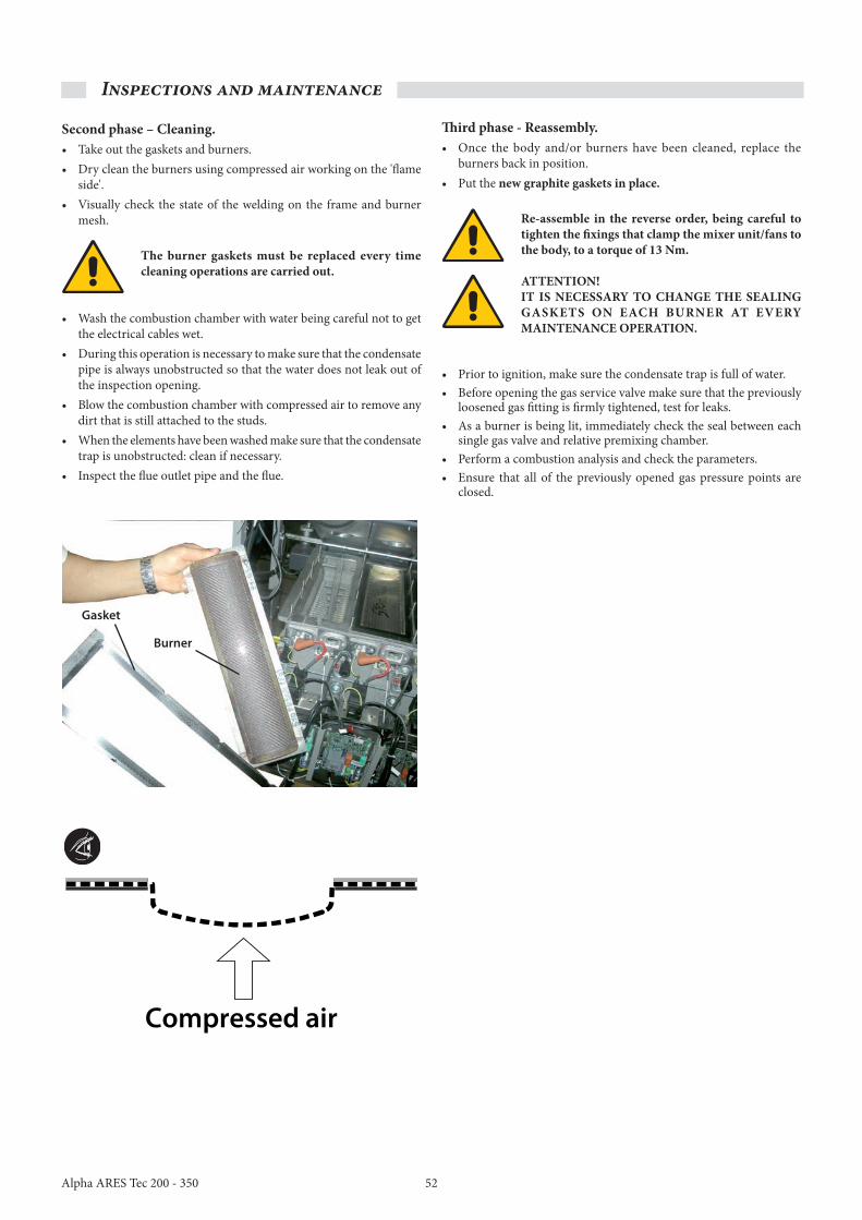
52
Inspections and maintenance
Alpha ARES Tec 200 - 350
Second phase – Cleaning.• Take out the gaskets and burners.• Dry clean the burners using compressed air working on the 'flame
side'.• Visually check the state of the welding on the frame and burner
mesh.
The burner gaskets must be replaced every time cleaning operations are carried out.
• Wash the combustion chamber with water being careful not to get the electrical cables wet.
• During this operation is necessary to make sure that the condensate pipe is always unobstructed so that the water does not leak out of the inspection opening.
• Blow the combustion chamber with compressed air to remove any dirt that is still attached to the studs.
• When the elements have been washed make sure that the condensate trap is unobstructed: clean if necessary.
• Inspect the flue outlet pipe and the flue.
Third phase - Reassembly.• Once the body and/or burners have been cleaned, replace the
burners back in position.• Put the new graphite gaskets in place.
Re-assemble in the reverse order, being careful to tighten the fixings that clamp the mixer unit/fans to the body, to a torque of 13 Nm.
ATTENTIoN!IT IS NECESSARy To ChANGE ThE SEALING GASkETS oN EACh BuRNER AT EvERy MAINTENANCE opERATIoN.
• Prior to ignition, make sure the condensate trap is full of water.• Before opening the gas service valve make sure that the previously
loosened gas fitting is firmly tightened, test for leaks.• As a burner is being lit, immediately check the seal between each
single gas valve and relative premixing chamber.• Perform a combustion analysis and check the parameters.• Ensure that all of the previously opened gas pressure points are
closed.
Burner
Gasket
Compressed air

53 Alpha ARES Tec 200 - 350

54Alpha ARES Tec 200 - 350

55 Alpha ARES Tec 200 - 350

The
inst
ruct
ion
book
let i
s prin
ted
on e
nviro
nmen
tally
-frie
ndly
pap
er.
Part
No.
1.0
3525
8 re
v. 15
.040
047/
000
- D32
4 - 0
8/20
13
During the service life of the product, performance is affected by external factors, e.g. the hardness of the DHW, atmospheric agents, deposits in the system and so on. The declared data refers to new products that are correctly installed and used in accordance with applicable regulations.Note: Correct periodic maintenance is highly recommended.
ISo 9001 certified company
www.alpha-innovation.co.ukFor Technical help or for Service call the Alpha Helpline or use the following e-mail:
[email protected] helpline 0844 871 8764
Alpha Therm LimitedNepicar house, London Road,wrotham heath, Sevenoaks, kentTN15 7RS