Embed Size (px)
Citation preview
© Copyright 2003-2005 Adaptive Micro Systems LLC. All rights reserved.Adaptive Micro Systems • 7840 North 86th Street • Milwaukee, WI 53224 USA • 414-357-2020 • 414-357-2029 (fax) • http://www.adaptivedisplays.com
Trademarked names appear throughout this document. Rather than list the names and entities that own the trademarks or insert a trademark symbol with each mention of the trademarked name, the publisher states that it is using names for editorial purposes and to the benefit of the trademark owner with no intention of improperly using the trademark.
The following are trademarks of Adaptive Micro Systems: Adaptive, Alpha, AlphaLert, AlphaNET, AlphaNet plus, AlphaEclipse, AlphaEclipse RoadStar, AlphaPremiere, AlphaTicker, AlphaVision, AlphaVision InfoTracker, Automode, BetaBrite, BetaBrite Director, BetaBrite Messaging Software, Big Dot, Director, EZ KEY II, EZ95, PagerNET, PPD, PrintPak, Serial Clock,
Smart Alec, Solar, TimeNet.The distinctive trade dress of this product is a trademark claimed by Adaptive Micro Systems LLC.
Due to continuing product innovation, specifications in this manual are subject to change without notice.
June 13, 2005 9711-2702F
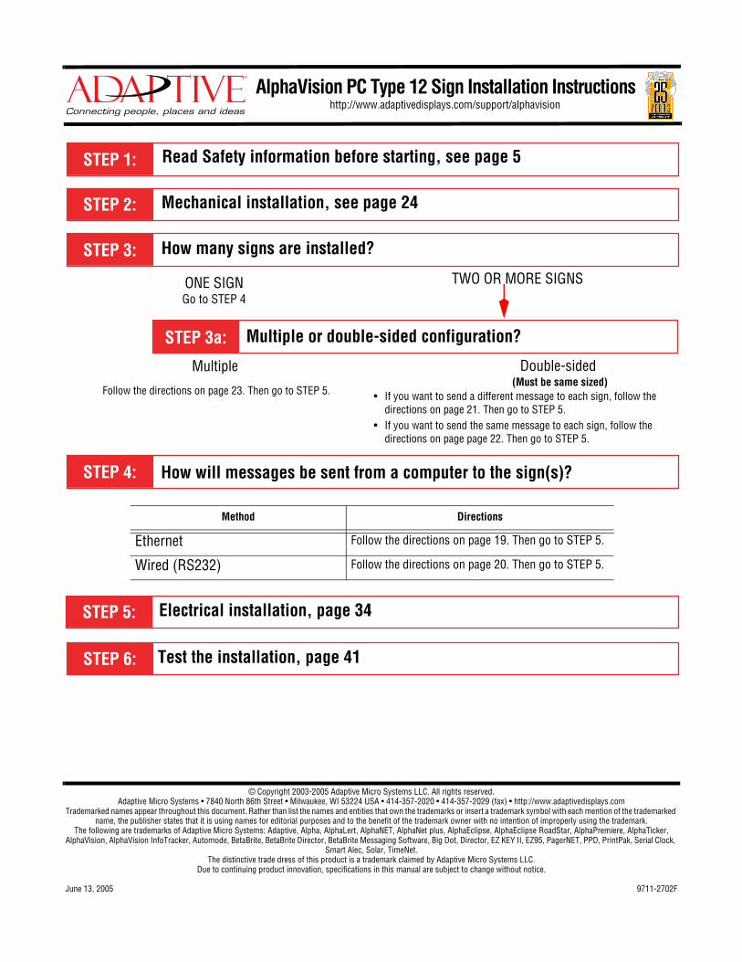
AlphaVision PC Type 12 Sign Installation Instructionshttp://www.adaptivedisplays.com/support/alphavision
Mechanical installation, see page 24
How many signs are installed?
Read Safety information before starting, see page 5
Method Directions
Ethernet Follow the directions on page 19. Then go to STEP 5.
Wired (RS232) Follow the directions on page 20. Then go to STEP 5.
ONE SIGNGo to STEP 4
Electrical installation, page 34
TWO OR MORE SIGNS
Multiple or double-sided configuration?
Multiple Double-sided
How will messages be sent from a computer to the sign(s)?
Follow the directions on page 23. Then go to STEP 5. • If you want to send a different message to each sign, follow the directions on page 21. Then go to STEP 5.
• If you want to send the same message to each sign, follow the directions on page page 22. Then go to STEP 5.
Test the installation, page 41
(Must be same sized)
June 13, 2005 AlphaVision PC Type 12 Sign Installation Instructions (pn 9711-2702F)
2 Contents
Contents
Introduction . . . . . . . . . . . . . . . . . . . . . . . . . . . . . . . . . . . . . . . . . . . . . . . . . . . . . . . . . . . . . . . . . . . . . . 4
Purpose . . . . . . . . . . . . . . . . . . . . . . . . . . . . . . . . . . . . . . . . . . . . . . . . . . . . . . . . . . . . . . . . . . . . . . . . . . . . . . . . . . . . . .4
Revision history . . . . . . . . . . . . . . . . . . . . . . . . . . . . . . . . . . . . . . . . . . . . . . . . . . . . . . . . . . . . . . . . . . . . . . . . . . . . . . . .4
Related documentation . . . . . . . . . . . . . . . . . . . . . . . . . . . . . . . . . . . . . . . . . . . . . . . . . . . . . . . . . . . . . . . . . . . . . . . . . .4
Safety information . . . . . . . . . . . . . . . . . . . . . . . . . . . . . . . . . . . . . . . . . . . . . . . . . . . . . . . . . . . . . . . . . . . . . . . . . . . . . .5
Equipment symbols. . . . . . . . . . . . . . . . . . . . . . . . . . . . . . . . . . . . . . . . . . . . . . . . . . . . . . . . . . . . . . . . . . . . . . . . .5
Warnings and cautions . . . . . . . . . . . . . . . . . . . . . . . . . . . . . . . . . . . . . . . . . . . . . . . . . . . . . . . . . . . . . . . . . . . . . .5
Preventing electrostatic discharge. . . . . . . . . . . . . . . . . . . . . . . . . . . . . . . . . . . . . . . . . . . . . . . . . . . . . . . . . . . . . .5
Equipment overview. . . . . . . . . . . . . . . . . . . . . . . . . . . . . . . . . . . . . . . . . . . . . . . . . . . . . . . . . . . . . . . . 6
Overview . . . . . . . . . . . . . . . . . . . . . . . . . . . . . . . . . . . . . . . . . . . . . . . . . . . . . . . . . . . . . . . . . . . . . . . . . . . . . . . . . . . . .6
Description . . . . . . . . . . . . . . . . . . . . . . . . . . . . . . . . . . . . . . . . . . . . . . . . . . . . . . . . . . . . . . . . . . . . . . . . . . . . . . . . . . .7
External views . . . . . . . . . . . . . . . . . . . . . . . . . . . . . . . . . . . . . . . . . . . . . . . . . . . . . . . . . . . . . . . . . . . . . . . . . . . . .7
Internal views . . . . . . . . . . . . . . . . . . . . . . . . . . . . . . . . . . . . . . . . . . . . . . . . . . . . . . . . . . . . . . . . . . . . . . . . . . . . .9
Equipment identification . . . . . . . . . . . . . . . . . . . . . . . . . . . . . . . . . . . . . . . . . . . . . . . . . . . . . . . . . . . . . . . . . . . . . . . .16
EMI compliance . . . . . . . . . . . . . . . . . . . . . . . . . . . . . . . . . . . . . . . . . . . . . . . . . . . . . . . . . . . . . . . . . . . . . . . . . . . . . . .17
Temperature protection . . . . . . . . . . . . . . . . . . . . . . . . . . . . . . . . . . . . . . . . . . . . . . . . . . . . . . . . . . . . . . . . . . . . . . . . .17
Networking signs . . . . . . . . . . . . . . . . . . . . . . . . . . . . . . . . . . . . . . . . . . . . . . . . . . . . . . . . . . . . . . . . . 18
Overview . . . . . . . . . . . . . . . . . . . . . . . . . . . . . . . . . . . . . . . . . . . . . . . . . . . . . . . . . . . . . . . . . . . . . . . . . . . . . . . . . . . .18
Computer-to-sign connection methods. . . . . . . . . . . . . . . . . . . . . . . . . . . . . . . . . . . . . . . . . . . . . . . . . . . . . . . . .18
Sign-to-sign connection methods . . . . . . . . . . . . . . . . . . . . . . . . . . . . . . . . . . . . . . . . . . . . . . . . . . . . . . . . . . . . .18
Single sign network choices . . . . . . . . . . . . . . . . . . . . . . . . . . . . . . . . . . . . . . . . . . . . . . . . . . . . . . . . . . . . . . . . . . . . .19
Ethernet. . . . . . . . . . . . . . . . . . . . . . . . . . . . . . . . . . . . . . . . . . . . . . . . . . . . . . . . . . . . . . . . . . . . . . . . . . . . . . . . .19
RS232 (Windows CE option only) . . . . . . . . . . . . . . . . . . . . . . . . . . . . . . . . . . . . . . . . . . . . . . . . . . . . . . . . . . . . .20
Double-sided sign network choices . . . . . . . . . . . . . . . . . . . . . . . . . . . . . . . . . . . . . . . . . . . . . . . . . . . . . . . . . . . . . . . .21
Master/Master . . . . . . . . . . . . . . . . . . . . . . . . . . . . . . . . . . . . . . . . . . . . . . . . . . . . . . . . . . . . . . . . . . . . . . . . . . . .21
Master/Slave . . . . . . . . . . . . . . . . . . . . . . . . . . . . . . . . . . . . . . . . . . . . . . . . . . . . . . . . . . . . . . . . . . . . . . . . . . . . .22
Multiple sign network choices . . . . . . . . . . . . . . . . . . . . . . . . . . . . . . . . . . . . . . . . . . . . . . . . . . . . . . . . . . . . . . . . . . . .23
Ethernet. . . . . . . . . . . . . . . . . . . . . . . . . . . . . . . . . . . . . . . . . . . . . . . . . . . . . . . . . . . . . . . . . . . . . . . . . . . . . . . . .23
Installation . . . . . . . . . . . . . . . . . . . . . . . . . . . . . . . . . . . . . . . . . . . . . . . . . . . . . . . . . . . . . . . . . . . . . . 24
Mechanical installation. . . . . . . . . . . . . . . . . . . . . . . . . . . . . . . . . . . . . . . . . . . . . . . . . . . . . . . . . . . . . . . . . . . . . . . . . .24
General warnings and cautions . . . . . . . . . . . . . . . . . . . . . . . . . . . . . . . . . . . . . . . . . . . . . . . . . . . . . . . . . . . . . . .24
Design of the support structure. . . . . . . . . . . . . . . . . . . . . . . . . . . . . . . . . . . . . . . . . . . . . . . . . . . . . . . . . . . . . . .25
Environmental requirements . . . . . . . . . . . . . . . . . . . . . . . . . . . . . . . . . . . . . . . . . . . . . . . . . . . . . . . . . . . . . . . . .25
Lifting the sign . . . . . . . . . . . . . . . . . . . . . . . . . . . . . . . . . . . . . . . . . . . . . . . . . . . . . . . . . . . . . . . . . . . . . . . . . . .25
Mounting the sign overhead . . . . . . . . . . . . . . . . . . . . . . . . . . . . . . . . . . . . . . . . . . . . . . . . . . . . . . . . . . . . . . . . .27
June 13, 2005 AlphaVision PC Type 12 Sign Installation Instructions (pn 9711-2702F)
Contents 3
Mounting the sign on a wall . . . . . . . . . . . . . . . . . . . . . . . . . . . . . . . . . . . . . . . . . . . . . . . . . . . . . . . . . . . . . . . . .30
Installation diagram. . . . . . . . . . . . . . . . . . . . . . . . . . . . . . . . . . . . . . . . . . . . . . . . . . . . . . . . . . . . . . . . . . . . . . . .33
Electrical installation . . . . . . . . . . . . . . . . . . . . . . . . . . . . . . . . . . . . . . . . . . . . . . . . . . . . . . . . . . . . . . . . . . . . . . . . . . .34
Guidelines for electrical installation. . . . . . . . . . . . . . . . . . . . . . . . . . . . . . . . . . . . . . . . . . . . . . . . . . . . . . . . . . . .34
Opening the sign . . . . . . . . . . . . . . . . . . . . . . . . . . . . . . . . . . . . . . . . . . . . . . . . . . . . . . . . . . . . . . . . . . . . . . . . . .36
Raising the LED boards. . . . . . . . . . . . . . . . . . . . . . . . . . . . . . . . . . . . . . . . . . . . . . . . . . . . . . . . . . . . . . . . . . . . .38
Installing signal wiring . . . . . . . . . . . . . . . . . . . . . . . . . . . . . . . . . . . . . . . . . . . . . . . . . . . . . . . . . . . . . . . . . . . . .39
Making power connections . . . . . . . . . . . . . . . . . . . . . . . . . . . . . . . . . . . . . . . . . . . . . . . . . . . . . . . . . . . . . . . . . .39
Closing the sign. . . . . . . . . . . . . . . . . . . . . . . . . . . . . . . . . . . . . . . . . . . . . . . . . . . . . . . . . . . . . . . . . . . . . . . . . . .41
Testing the installation . . . . . . . . . . . . . . . . . . . . . . . . . . . . . . . . . . . . . . . . . . . . . . . . . . . . . . . . . . . . . . . . . . . . . . . . . .41
Appendices . . . . . . . . . . . . . . . . . . . . . . . . . . . . . . . . . . . . . . . . . . . . . . . . . . . . . . . . . . . . . . . . . . . . . 42
Technical specifications . . . . . . . . . . . . . . . . . . . . . . . . . . . . . . . . . . . . . . . . . . . . . . . . . . . . . . . . . . . . . . . . . . . . . . . . .42
Mains power wiring . . . . . . . . . . . . . . . . . . . . . . . . . . . . . . . . . . . . . . . . . . . . . . . . . . . . . . . . . . . . . . . . . . . . . . . . . . . .46
Sign options. . . . . . . . . . . . . . . . . . . . . . . . . . . . . . . . . . . . . . . . . . . . . . . . . . . . . . . . . . . . . . . . . . . . . . . . . . . . . . . . . .47
Speaker outputs . . . . . . . . . . . . . . . . . . . . . . . . . . . . . . . . . . . . . . . . . . . . . . . . . . . . . . . . . . . . . . . . . . . . . . . . . .47
5 VDC output. . . . . . . . . . . . . . . . . . . . . . . . . . . . . . . . . . . . . . . . . . . . . . . . . . . . . . . . . . . . . . . . . . . . . . . . . . . . .48
Relay outputs . . . . . . . . . . . . . . . . . . . . . . . . . . . . . . . . . . . . . . . . . . . . . . . . . . . . . . . . . . . . . . . . . . . . . . . . . . . .48
Setting an IP address. . . . . . . . . . . . . . . . . . . . . . . . . . . . . . . . . . . . . . . . . . . . . . . . . . . . . . . . . . . . . . . . . . . . . . . . . . .49
Windows 2000 option . . . . . . . . . . . . . . . . . . . . . . . . . . . . . . . . . . . . . . . . . . . . . . . . . . . . . . . . . . . . . . . . . . . . . . . . . .51
Install the VNC Viewer. . . . . . . . . . . . . . . . . . . . . . . . . . . . . . . . . . . . . . . . . . . . . . . . . . . . . . . . . . . . . . . . . . . . . .51
Run the VNC Viewer . . . . . . . . . . . . . . . . . . . . . . . . . . . . . . . . . . . . . . . . . . . . . . . . . . . . . . . . . . . . . . . . . . . . . . .51
Set the sign’s IP address. . . . . . . . . . . . . . . . . . . . . . . . . . . . . . . . . . . . . . . . . . . . . . . . . . . . . . . . . . . . . . . . . . . .52
Install software on the sign’s hard drive . . . . . . . . . . . . . . . . . . . . . . . . . . . . . . . . . . . . . . . . . . . . . . . . . . . . . . . .53
Configure the sign . . . . . . . . . . . . . . . . . . . . . . . . . . . . . . . . . . . . . . . . . . . . . . . . . . . . . . . . . . . . . . . . . . . . . . . . .55
Remove the hard drive . . . . . . . . . . . . . . . . . . . . . . . . . . . . . . . . . . . . . . . . . . . . . . . . . . . . . . . . . . . . . . . . . . . . .57
June 13, 2005 AlphaVision PC Type 12 Sign Installation Instructions (pn 9711-2702F)
4 1 — Introduction
1 — Introduction
Purpose
This manual is intended as a guide for installation and setup of the sign, as well as for routine maintenance. There are no user serviceable parts inside the sign.
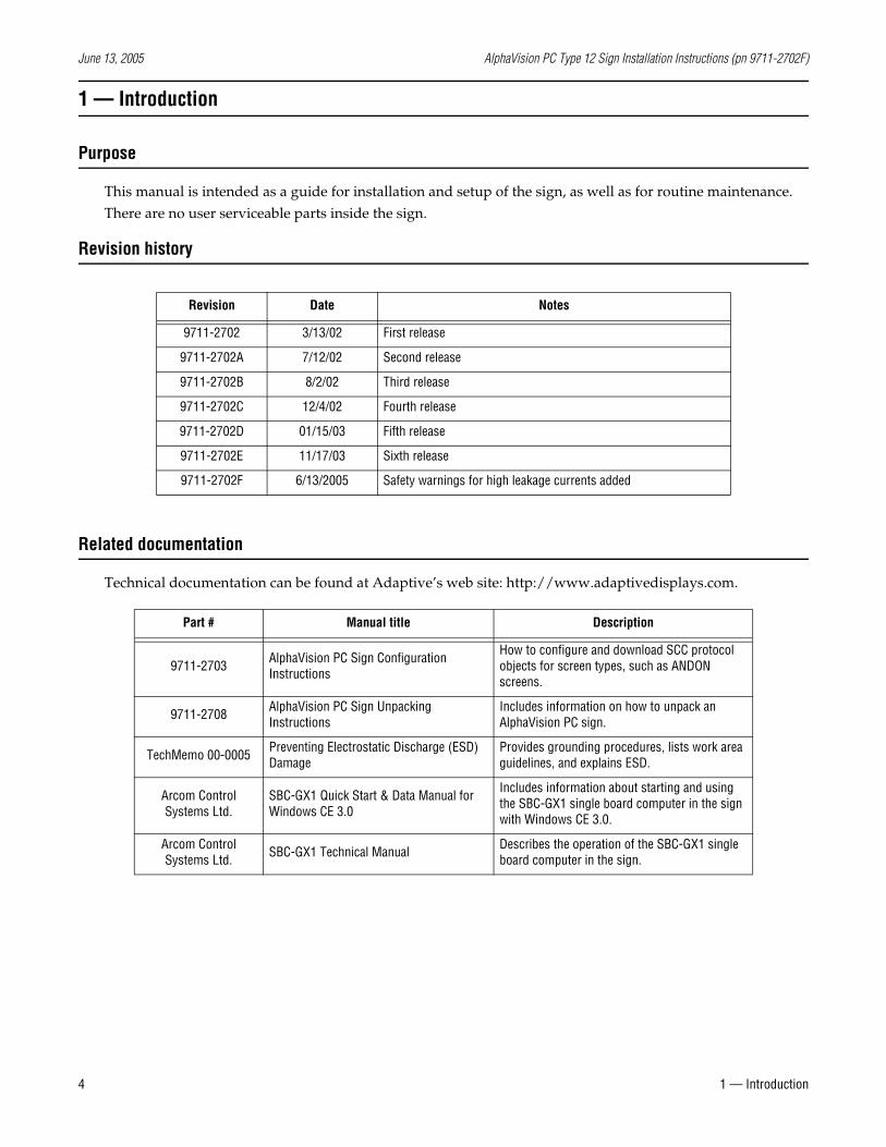
Revision history
Related documentation
Technical documentation can be found at Adaptive’s web site: http://www.adaptivedisplays.com.
Revision Date Notes
9711-2702 3/13/02 First release
9711-2702A 7/12/02 Second release
9711-2702B 8/2/02 Third release
9711-2702C 12/4/02 Fourth release
9711-2702D 01/15/03 Fifth release
9711-2702E 11/17/03 Sixth release
9711-2702F 6/13/2005 Safety warnings for high leakage currents added
Part # Manual title Description
9711-2703 AlphaVision PC Sign Configuration Instructions
How to configure and download SCC protocol objects for screen types, such as ANDON screens.
9711-2708 AlphaVision PC Sign Unpacking Instructions
Includes information on how to unpack an AlphaVision PC sign.
TechMemo 00-0005 Preventing Electrostatic Discharge (ESD) Damage
Provides grounding procedures, lists work area guidelines, and explains ESD.
Arcom Control Systems Ltd.
SBC-GX1 Quick Start & Data Manual for Windows CE 3.0
Includes information about starting and using the SBC-GX1 single board computer in the sign with Windows CE 3.0.
Arcom Control Systems Ltd. SBC-GX1 Technical Manual Describes the operation of the SBC-GX1 single
board computer in the sign.
June 13, 2005 AlphaVision PC Type 12 Sign Installation Instructions (pn 9711-2702F)
1 — Introduction 5
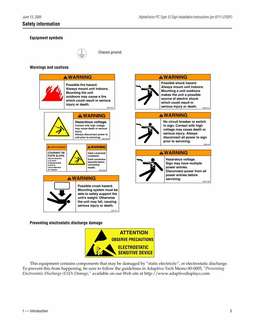
Safety information
Equipment symbols
Warnings and cautions
Preventing electrostatic discharge damage
This equipment contains components that may be damaged by “static electricity”, or electrostatic discharge. To prevent this from happening, be sure to follow the guidelines in Adaptive Tech Memo 00-0005, “Preventing Electrostatic Discharge (ESD) Damage,” available on our Web site at http://www.adaptivedisplays.com.
Chassis ground
Possible fire hazard. Always mount unit indoors. Mounting the unitoutdoors may cause a fire which could result in serious injury or death.
WARNING
SM1007A
WARNINGPossible shock hazard. Always mount unit indoors.Mounting a unit outdoorsmakes the unit a possiblesource of electric shockwhich could result in serious injury or death.
SM1001A
No circuit breaker or switch in sign. Contact with high voltage may cause death or serious injury. Always disconnect all power to sign prior to servicing.
WARNING
SM1010
Contact with high voltagemay cause death or seriousinjury.Always disconnect power to unit prior to servicing.
Hazardous voltage.
WARNING
SM1000A
HIGH LEAKAGECURRENT.
COURANT DEFUITE ELEVE.
Earth connectionessential beforeconnectingsupply.
Raccordementa la terreindispensableavant leraccordementau reseau.
AVERTISSEMENT WARNING
SM1009A
Hazardous voltage. Sign may have multiplepower entries.Disconnect power from all power entries beforeservicing.
WARNING
SM1016B
Possible crush hazard.Mounting system must be able to safely support the unit's weight. Otherwise the unit may fall, causing serious injury or death.
WARNING
SM1014
ATTENTIONOBSERVE PRECAUTIONS
ELECTROSTATICSENSITIVE DEVICE
June 13, 2005 AlphaVision PC Type 12 Sign Installation Instructions (pn 9711-2702F)
6 2 — Equipment overview
2 — Equipment overview
Overview
The AlphaVision PC sign has either an embedded computer (for process control) running Microsoft Windows CE, or an internal hard disk drive running Microsoft Windows 2000. This sign is for indoor use only.
Signs can be networked to other signs and to a computer network using:
• Ethernet (10BASE-T or 100BASE-T)
• RS232 (Windows CE only)
Protocol options (Windows CE only) include:
• Static Controls Corp. SCC protocol
• Alpha pixel protocol
• ActiveX
Other features include:
• Tri-color: red, green, amber
• Type 12 enclosure
• Built-in support for speaker output
• Front-serviceable
• 6-month battery-backup
• Time and date supported by a real-time clock
• Connections for auxiliary output, such as an alarm
Data — including messages, fonts and graphics — can be downloaded from a computer system to AlphaVision PC signs. Signs are addressed by IP address using Ethernet.
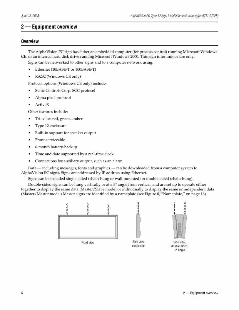
Signs can be installed single-sided (chain-hung or wall-mounted) or double-sided (chain-hung).Double-sided signs can be hung vertically or at a 5° angle from vertical, and are set up to operate either
together to display the same data (Master/Slave mode) or individually to display the same or independent data (Master/Master mode.) Master signs are identified by a nameplate (see Figure 8, “Nameplate,” on page 16).
Front view Side view,double-sided,
5° angle
Side view,single sign
June 13, 2005 AlphaVision PC Type 12 Sign Installation Instructions (pn 9711-2702F)
2 — Equipment overview 7
Description
External views
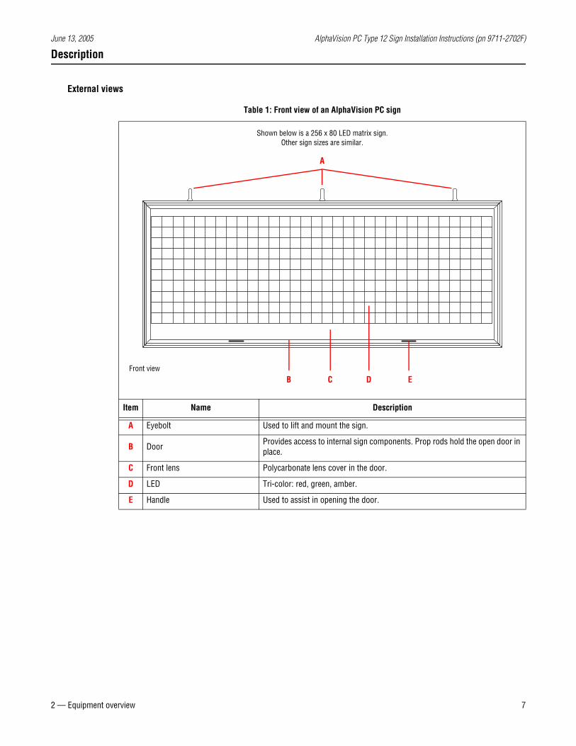
Table 1: Front view of an AlphaVision PC sign
Item Name Description
A Eyebolt Used to lift and mount the sign.
B Door Provides access to internal sign components. Prop rods hold the open door in place.
C Front lens Polycarbonate lens cover in the door.
D LED Tri-color: red, green, amber.
E Handle Used to assist in opening the door.
Shown below is a 256 x 80 LED matrix sign.Other sign sizes are similar.
Front viewB C D
A
E
June 13, 2005 AlphaVision PC Type 12 Sign Installation Instructions (pn 9711-2702F)
8 2 — Equipment overview
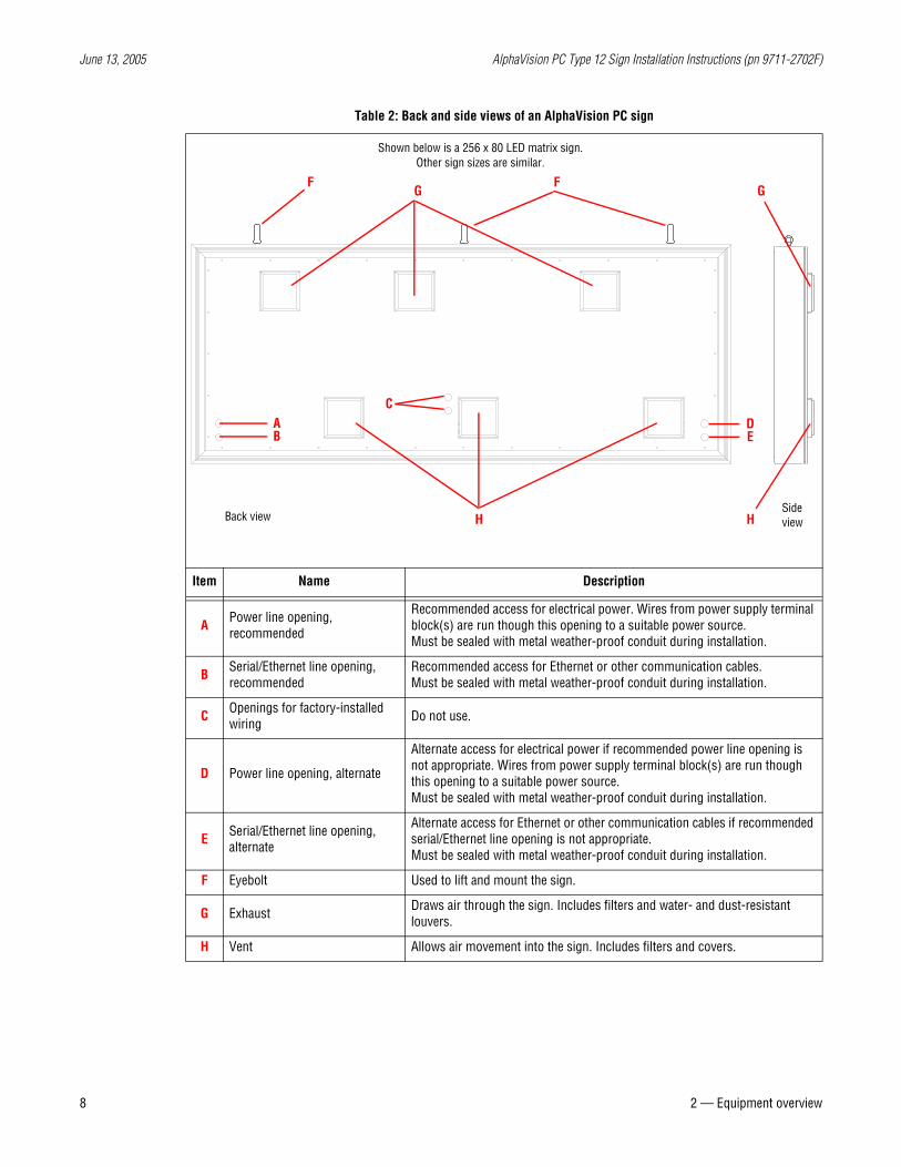
Table 2: Back and side views of an AlphaVision PC sign
Item Name Description
A Power line opening, recommended
Recommended access for electrical power. Wires from power supply terminal block(s) are run though this opening to a suitable power source.Must be sealed with metal weather-proof conduit during installation.
B Serial/Ethernet line opening, recommended
Recommended access for Ethernet or other communication cables. Must be sealed with metal weather-proof conduit during installation.
C Openings for factory-installed wiring Do not use.
D Power line opening, alternate
Alternate access for electrical power if recommended power line opening is not appropriate. Wires from power supply terminal block(s) are run though this opening to a suitable power source.Must be sealed with metal weather-proof conduit during installation.
E Serial/Ethernet line opening, alternate
Alternate access for Ethernet or other communication cables if recommended serial/Ethernet line opening is not appropriate. Must be sealed with metal weather-proof conduit during installation.
F Eyebolt Used to lift and mount the sign.
G Exhaust Draws air through the sign. Includes filters and water- and dust-resistant louvers.
H Vent Allows air movement into the sign. Includes filters and covers.
Back view
Shown below is a 256 x 80 LED matrix sign.Other sign sizes are similar.
Side viewH
CDE
GF F
AB
G
H
June 13, 2005 AlphaVision PC Type 12 Sign Installation Instructions (pn 9711-2702F)
2 — Equipment overview 9
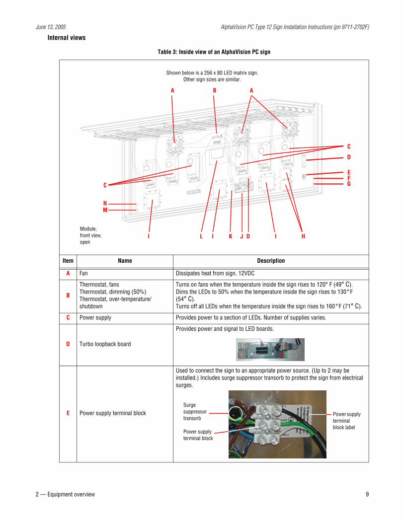
Internal views
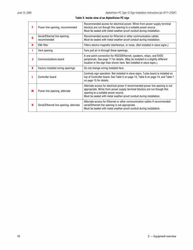
Table 3: Inside view of an AlphaVision PC sign
Item Name Description
A Fan Dissipates heat from sign. 12VDC
B
Thermostat, fansThermostat, dimming (50%)Thermostat, over-temperature/shutdown
Turns on fans when the temperature inside the sign rises to 120° F (49° C). Dims the LEDs to 50% when the temperature inside the sign rises to 130° F(54° C). Turns off all LEDs when the temperature inside the sign rises to 160° F (71° C).
C Power supply Provides power to a section of LEDs. Number of supplies varies.
D Turbo loopback board
Provides power and signal to LED boards.
E Power supply terminal block
Used to connect the sign to an appropriate power source. (Up to 2 may be installed.) Includes surge suppressor transorb to protect the sign from electrical surges.
Shown below is a 256 x 80 LED matrix sign. Other sign sizes are similar.
Module, front view, open
A AB
C
C
HIJII
EFG
L K
NM
D
D
Power supply terminal block
Surge suppressor transorb
Power supply terminal block label
June 13, 2005 AlphaVision PC Type 12 Sign Installation Instructions (pn 9711-2702F)
10 2 — Equipment overview
F Power line opening, recommendedRecommended access for electrical power. Wires from power supply terminal block(s) are run though this opening to a suitable power source.Must be sealed with metal weather-proof conduit during installation.
G Serial/Ethernet line opening, recommended
Recommended access for Ethernet or other communication cables. Must be sealed with metal weather-proof conduit during installation.
H EMI filter Filters electro-magnetic interference, or noise. (Not installed in slave signs.)
I Vent opening Fans pull air in through these openings.
J Communications boardA one-point connection for RS232Ethernet, speakers, relays, and 5VDC peripherals. See page 11 for details. (May be installed in a slightly different location in the sign than shown here. Not installed in slave signs.)
K Factory-installed wiring openings Do not change wiring installed here.
L Controller boardControls sign operation. Not installed in slave signs. Turbo board is installed on top of Controller board. See Table 5 on page 13, Table 6 on page 14, and Table 7 on page 15 for details.
M Power line opening, alternate
Alternate access for electrical power if recommended power line opening is not appropriate. Wires from power supply terminal block(s) are run though this opening to a suitable power source.Must be sealed with metal weather-proof conduit during installation.
N Serial/Ethernet line opening, alternateAlternate access for Ethernet or other communication cables if recommended serial/Ethernet line opening is not appropriate. Must be sealed with metal weather-proof conduit during installation.
Table 3: Inside view of an AlphaVision PC sign
June 13, 2005 AlphaVision PC Type 12 Sign Installation Instructions (pn 9711-2702F)
2 — Equipment overview 11
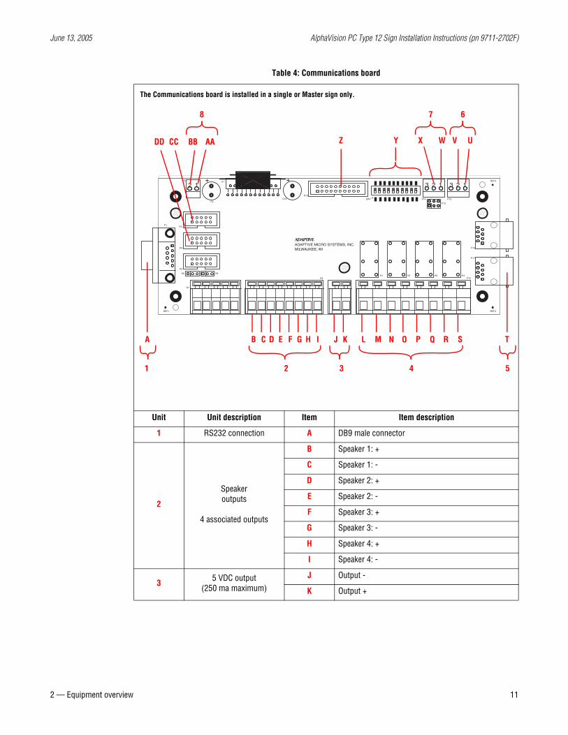
Table 4: Communications board
Unit Unit description Item Item description
1 RS232 connection A DB9 male connector
2
Speakeroutputs
4 associated outputs
B Speaker 1: +
C Speaker 1: -
D Speaker 2: +
E Speaker 2: -
F Speaker 3: +
G Speaker 3: -
H Speaker 4: +
I Speaker 4: -
3 5 VDC output(250 ma maximum)
J Output -
K Output +
P14
REF1
P5
P6
P4
P8
P3P1
P2
C4
U1
P9K1 K2
C19P10
SW1
REF3
K3 K4P12
P17
P16
P13
P15
REF2
3 2 1 3 2 12 1
ADAPTIVE MICRO SYSTEMS, INC.MILWAUKEE, WI
ADAPTIVE
P7
A B C D E F G H I J K L M N O P Q R S T
Y
2 3 41 5
The Communications board is installed in a single or Master sign only.
Z X V UWBB AA
8 7 6
DD CC
June 13, 2005 AlphaVision PC Type 12 Sign Installation Instructions (pn 9711-2702F)
12 2 — Equipment overview
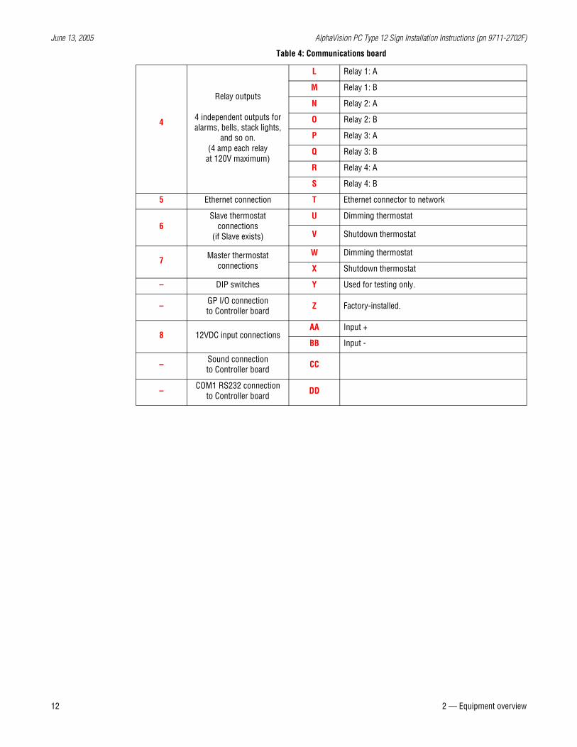
4
Relay outputs
4 independent outputs foralarms, bells, stack lights,
and so on.(4 amp each relay
at 120V maximum)
L Relay 1: A
M Relay 1: B
N Relay 2: A
O Relay 2: B
P Relay 3: A
Q Relay 3: B
R Relay 4: A
S Relay 4: B
5 Ethernet connection T Ethernet connector to network
6Slave thermostat
connections(if Slave exists)
U Dimming thermostat
V Shutdown thermostat
7 Master thermostat connections
W Dimming thermostat
X Shutdown thermostat
– DIP switches Y Used for testing only.
– GP I/O connection to Controller board Z Factory-installed.
8 12VDC input connectionsAA Input +
BB Input -
– Sound connection to Controller board CC
– COM1 RS232 connection to Controller board DD
Table 4: Communications board
June 13, 2005 AlphaVision PC Type 12 Sign Installation Instructions (pn 9711-2702F)
2 — Equipment overview 13
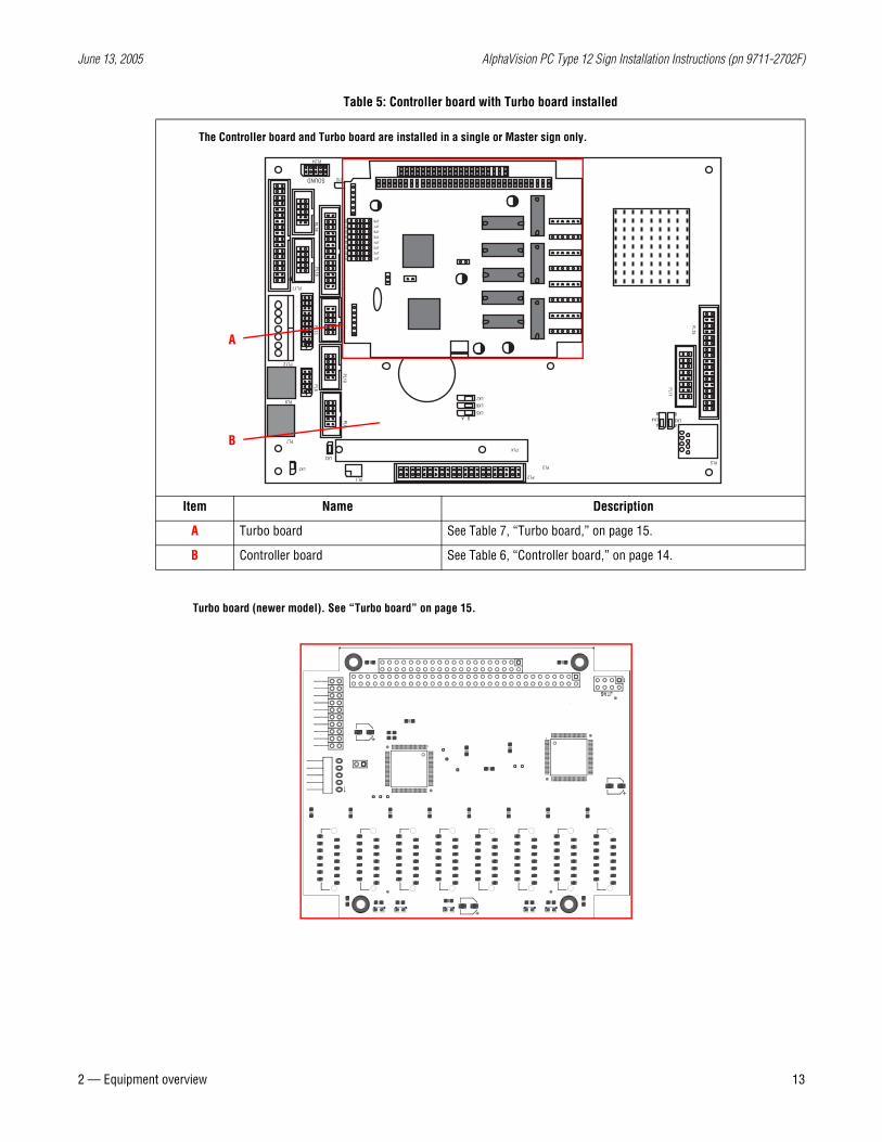
Table 5: Controller board with Turbo board installed
Item Name Description
A Turbo board See Table 7, “Turbo board,” on page 15.
B Controller board See Table 6, “Controller board,” on page 14.
The Controller board and Turbo board are installed in a single or Master sign only.
LK3A
BLK4A
B
PL15
PL11
PL5
LK5
LK6
LK7
B A
PL20
PL22
PL23
B32LK11
PL21LK12
PL24
PL6
PL1
LK2
LK1
PL8
PL12
PL9
PL7
LK8
LK9
LK10PL10
PL14PL16
PL18PL19
PL17
PL13
SOUND
PL3
PL2
PL4
B1A1
C0D0
FLASHSUSPPOW
JP8
JP7
JP6
JP5
JP4
JP3
JP2
JP1
R1R2
R3R4
R5R6
R7R8
B
A
Turbo board (newer model). See “Turbo board” on page 15.
June 13, 2005 AlphaVision PC Type 12 Sign Installation Instructions (pn 9711-2702F)
14 2 — Equipment overview
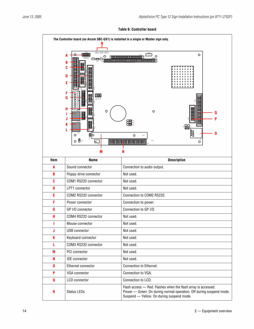
Table 6: Controller board
Item Name Description
A Sound connector Connection to audio output.
B Floppy drive connector Not used.
C COM1 RS232 connector Not used.
D LPT1 connector Not used.
E COM2 RS232 connector Connection to COM2 RS232.
F Power connector Connection to power.
G GP I/O connector Connection to GP I/O.
H COM4 RS232 connector Not used.
I Mouse connector Not used.
J USB connector Not used.
K Keyboard connector Not used.
L COM3 RS232 connector Not used.
M PCI connector Not used.
N IDE connector Not used.
O Ethernet connector Connection to Ethernet.
P VGA connector Connection to VGA.
Q LCD connector Connection to LCD.
R Status LEDsFlash access — Red. Flashes when the flash array is accessed.Power — Green. On during normal operation. Off during suspend mode.Suspend — Yellow. On during suspend mode.
LK3A
BLK4A
B
PL15
PL11
PL5
LK5
LK6
LK7
B A
PL20
PL22
PL23
B32LK11
PL21LK12
PL24
PL6
PL1
LK2
LK1
PL8
PL12
PL9
PL7
LK8
LK9
LK10PL10
PL14PL16
PL18PL19
PL17
PL13
SOUND
PL3
PL2
PL4
B1A1
C0D0
FLASHSUSPPOW
The Controller board (an Arcom SBC-GX1) is installed in a single or Master sign only.
BC
D
E
FG
HIJKL
M N
P
Q
O
A
R
June 13, 2005 AlphaVision PC Type 12 Sign Installation Instructions (pn 9711-2702F)
2 — Equipment overview 15
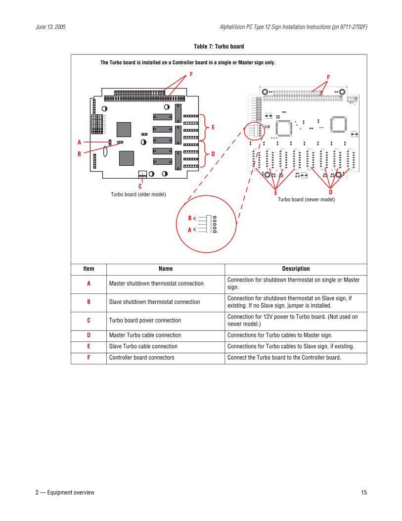
Table 7: Turbo board
Item Name Description
A Master shutdown thermostat connection Connection for shutdown thermostat on single or Master sign.
B Slave shutdown thermostat connection Connection for shutdown thermostat on Slave sign, if existing. If no Slave sign, jumper is installed.
C Turbo board power connection Connection for 12V power to Turbo board. (Not used on newer model.)
D Master Turbo cable connection Connections for Turbo cables to Master sign.
E Slave Turbo cable connection Connections for Turbo cables to Slave sign, if existing.
F Controller board connectors Connect the Turbo board to the Controller board.
JP8
JP7
JP6
JP5
JP4
JP3
JP2
JP1
R1R2
R3R4
R5R6
R7R8
E
The Turbo board is installed on a Controller board in a single or Master sign only.
A
B D
C
F F
Turbo board (older model)Turbo board (newer model)
DE
A
B
June 13, 2005 AlphaVision PC Type 12 Sign Installation Instructions (pn 9711-2702F)
16 2 — Equipment overview
Equipment identification
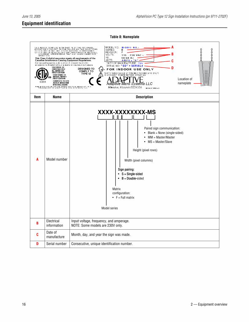
Table 8: Nameplate
Item Name Description
A Model number
B Electrical information
Input voltage, frequency, and amperage. NOTE: Some models are 230V only.
C Date of manufacture Month, day, and year the sign was made.
D Serial number Consecutive, unique identification number.
A
B
C
D
Location of nameplate
XXXX-XXXXXXXX-MS
Model series
Matrix configuration:• F = Full matrix
Width (pixel columns)
Sign pairing:• S = Single-sided• B = Double-
Height (pixel rows)
Paired sign communication:• Blank = None (single-sided)• MM = Master/Master• MS = Master/Slave
Sign pairing:• S = Single-sided• B = Double-sided
June 13, 2005 AlphaVision PC Type 12 Sign Installation Instructions (pn 9711-2702F)
2 — Equipment overview 17
EMI compliance
This equipment has been tested and found to comply with the limits for a Class A digital device, pursuant to Part 15 of the FCC Rules. These limits are designed to provide reasonable protection against harmful interference when the equipment is operated in a commercial environment.
This equipment generates, uses, and can radiate radio frequency energy and, if not installed and used in accordance with installation guidelines, may cause harmful interference to radio communications. Operation of this equipment in a residential area is likely to cause harmful interference, in which case the user will be required to correct the interference at his own expense.
Temperature protection
Internal thermostats protect the sign from excessive heat.
• If the sign’s internal temperature rises to or above 120° F (49° C), the fans are switched on by the fan thermostat. If the internal temperature drops to 90° F (32° C), then the fans are turned off.
• If the sign’s internal temperature rises to or above 130° F (54° C), auto-dimming occurs. This means that the LED output from the sign is forced into a 50% reduced power mode, effectively dimming the brightness of LED output by about 50%. If the internal temperature falls to 100° F (38° C), then auto-dimming stops.
• If the sign’s internal temperature rises to or above 160° F (71° C), the sign automatically shuts down to protect the sign against damage. If the internal temperature falls to 130° F (54° C) or less, the sign resumes operation in auto-dim mode (50% brightness) as described above.
June 13, 2005 AlphaVision PC Type 12 Sign Installation Instructions (pn 9711-2702F)
18 3 — Networking signs
3 — Networking signs
Overview
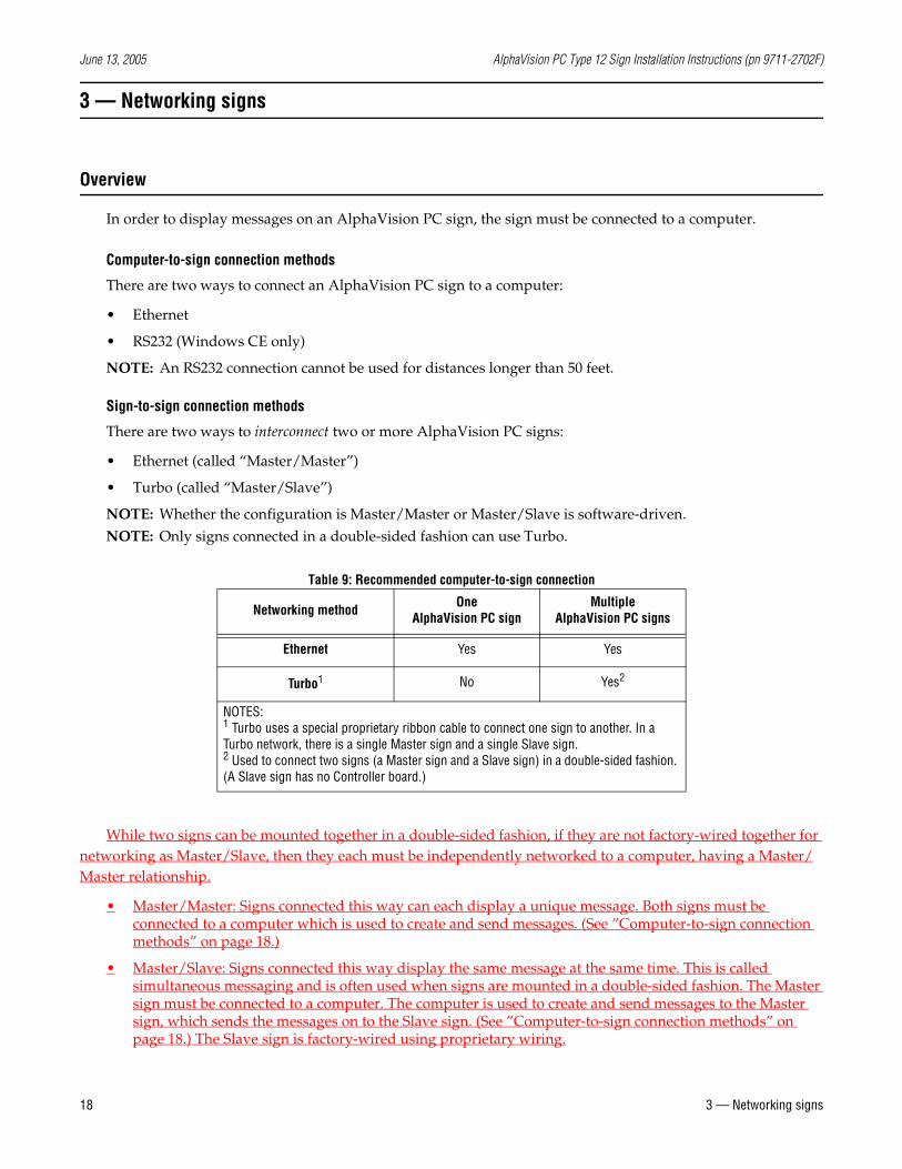
In order to display messages on an AlphaVision PC sign, the sign must be connected to a computer.
Computer-to-sign connection methods
There are two ways to connect an AlphaVision PC sign to a computer:
• Ethernet
• RS232 (Windows CE only)
NOTE: An RS232 connection cannot be used for distances longer than 50 feet.
Sign-to-sign connection methods
There are two ways to interconnect two or more AlphaVision PC signs:
• Ethernet (called “Master/Master”)
• Turbo (called “Master/Slave”)
NOTE: Whether the configuration is Master/Master or Master/Slave is software-driven. NOTE: Only signs connected in a double-sided fashion can use Turbo.
Table 9: Recommended computer-to-sign connection
While two signs can be mounted together in a double-sided fashion, if they are not factory-wired together for networking as Master/Slave, then they each must be independently networked to a computer, having a Master/Master relationship.
• Master/Master: Signs connected this way can each display a unique message. Both signs must be connected to a computer which is used to create and send messages. (See ”Computer-to-sign connection methods” on page 18.)
• Master/Slave: Signs connected this way display the same message at the same time. This is called simultaneous messaging and is often used when signs are mounted in a double-sided fashion. The Master sign must be connected to a computer. The computer is used to create and send messages to the Master sign, which sends the messages on to the Slave sign. (See ”Computer-to-sign connection methods” on page 18.) The Slave sign is factory-wired using proprietary wiring.
Networking method OneAlphaVision PC sign
MultipleAlphaVision PC signs
Ethernet Yes Yes
Turbo1 No Yes2
NOTES:1 Turbo uses a special proprietary ribbon cable to connect one sign to another. In a Turbo network, there is a single Master sign and a single Slave sign.2 Used to connect two signs (a Master sign and a Slave sign) in a double-sided fashion. (A Slave sign has no Controller board.)
June 13, 2005 AlphaVision PC Type 12 Sign Installation Instructions (pn 9711-2702F)
3 — Networking signs 19
Single sign network choices
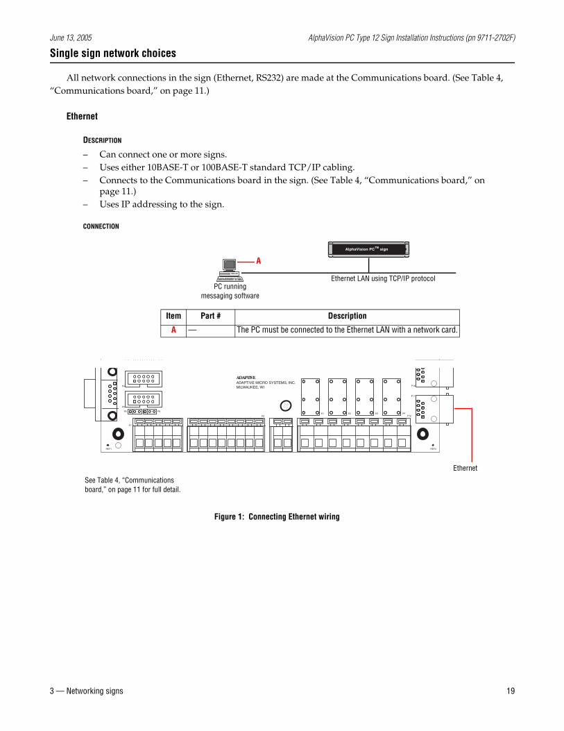
All network connections in the sign (Ethernet, RS232) are made at the Communications board. (See Table 4, “Communications board,” on page 11.)
Ethernet
DESCRIPTION
– Can connect one or more signs.– Uses either 10BASE-T or 100BASE-T standard TCP/IP cabling.– Connects to the Communications board in the sign. (See Table 4, “Communications board,” on
page 11.)– Uses IP addressing to the sign.
CONNECTION
AlphaVision PCTM sign
A
Item Part # Description
A — The PC must be connected to the Ethernet LAN with a network card.
PC runningmessaging software
Ethernet LAN using TCP/IP protocol
REF1
P5
P6
P4
P8
P3P1
P9K1 K2
REF3
K3 K4P12
P17
P16ADAPTIVE MICRO SYSTEMS, INC.MILWAUKEE, WI
ADAPTIVE
P7
See Table 4, “Communications board,” on page 11 for full detail.
Figure 1: Connecting Ethernet wiring
Ethernet
June 13, 2005 AlphaVision PC Type 12 Sign Installation Instructions (pn 9711-2702F)
20 3 — Networking signs
RS232 (Windows CE option only)
DESCRIPTION
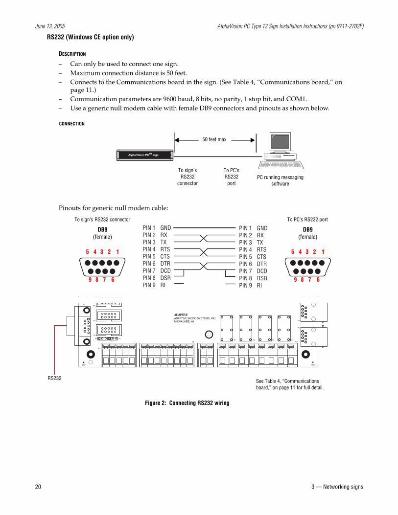
– Can only be used to connect one sign.– Maximum connection distance is 50 feet.– Connects to the Communications board in the sign. (See Table 4, “Communications board,” on
page 11.)– Communication parameters are 9600 baud, 8 bits, no parity, 1 stop bit, and COM1.– Use a generic null modem cable with female DB9 connectors and pinouts as shown below.
CONNECTION
Pinouts for generic null modem cable:
PC running messaging software
To sign’s RS232
connector
To PC’s RS232
port
50 feet max.
AlphaVision PCTM sign
12345
6789
GNDRXTXRTSCTSDTRDCDDSRRI
PIN 1PIN 2PIN 3PIN 4PIN 5PIN 6PIN 7PIN 8PIN 9
GNDRXTXRTSCTSDTRDCDDSRRI
PIN 1PIN 2PIN 3PIN 4PIN 5PIN 6PIN 7PIN 8PIN 9
DB9(female)
12345
6789
DB9(female)
To sign’s RS232 connector To PC’s RS232 port
REF1
P5
P6
P4
P8
P3P1
P9K1 K2
REF3
K3 K4P12
P17
P16ADAPTIVE MICRO SYSTEMS, INC.MILWAUKEE, WI
ADAPTIVE
P7
See Table 4, “Communications board,” on page 11 for full detail.
Figure 2: Connecting RS232 wiring
RS232
June 13, 2005 AlphaVision PC Type 12 Sign Installation Instructions (pn 9711-2702F)
3 — Networking signs 21
Double-sided sign network choices
Signs that are in a double-sided configuration are software-driven for a Master/Master or Master/Slave connection. It depends on the software loaded in the embedded controller on the Master sign.
Master/Master
DESCRIPTION
– A different message can be displayed on each sign. This differs from a Master-Slave connection in which the same message must be displayed on both signs.
– Connects to the Communications board in the sign. (See Table 4, “Communications board,” on page 11.)
CONNECTION
– See ”Ethernet” on page 19.– See “RS232 (Windows CE option only)” on page 20.
June 13, 2005 AlphaVision PC Type 12 Sign Installation Instructions (pn 9711-2702F)
22 3 — Networking signs
Master/Slave
DESCRIPTION
– The same message can be displayed on each sign.
CONNECTION
– See ”Ethernet” on page 19.– See ”RS232 (Windows CE option only)” on page 20.
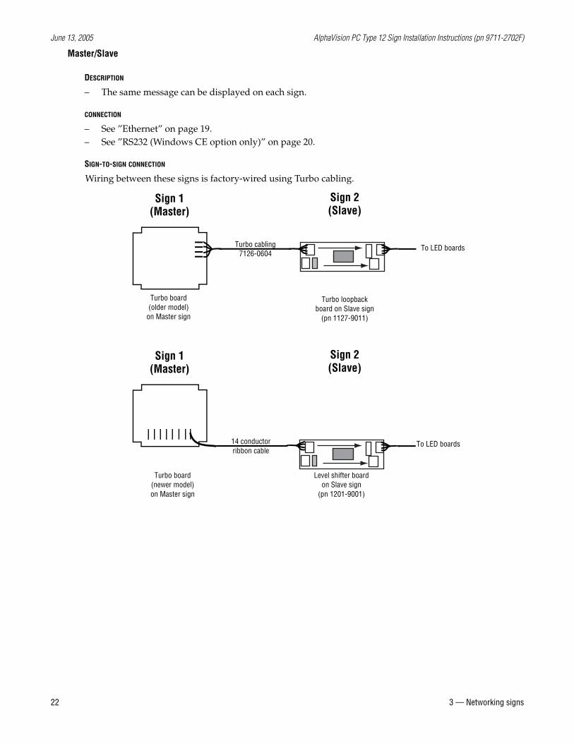
SIGN-TO-SIGN CONNECTION
Wiring between these signs is factory-wired using Turbo cabling.
Sign 1(Master)
Turbo board (older model)
on Master sign
Turbo cabling7126-0604
Sign 2(Slave)
Turbo loopback board on Slave sign
(pn 1127-9011)
To LED boards
Sign 1(Master)
Turbo board (newer model)on Master sign
14 conductor ribbon cable
Sign 2(Slave)
Level shifter board on Slave sign
(pn 1201-9001)
To LED boards
June 13, 2005 AlphaVision PC Type 12 Sign Installation Instructions (pn 9711-2702F)
3 — Networking signs 23
Multiple sign network choices
Multiple signs can be connected using Ethernet.
Ethernet
DESCRIPTION
– Can connect one or more signs.– Use either 10BASE-T or 100BASE-T standard TCP/IP cabling.– Connects to the Communications board in the sign. (See Table 4, “Communications board,” on
page 11.)– Uses IP addressing to the sign.– A different message can be displayed on each sign.
CONNECTION
– See ”Ethernet” on page 19.
June 13, 2005 AlphaVision PC Type 12 Sign Installation Instructions (pn 9711-2702F)
24 4 — Installation
4 — Installation
Mechanical installation
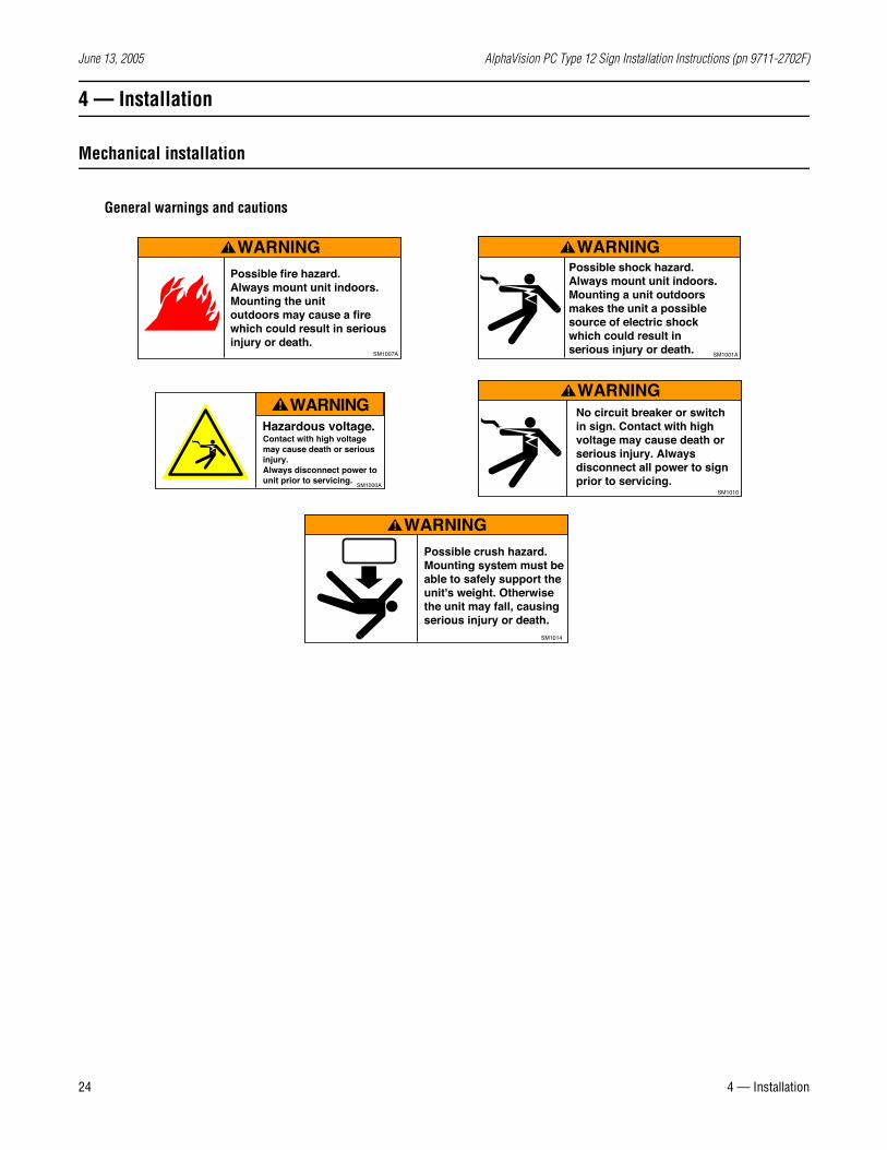
General warnings and cautions
Possible fire hazard. Always mount unit indoors. Mounting the unitoutdoors may cause a fire which could result in serious injury or death.
WARNING
SM1007A
WARNINGPossible shock hazard. Always mount unit indoors.Mounting a unit outdoorsmakes the unit a possiblesource of electric shockwhich could result in serious injury or death.
SM1001A
Contact with high voltagemay cause death or seriousinjury.Always disconnect power to unit prior to servicing.
Hazardous voltage.
WARNING
SM1000A
No circuit breaker or switch in sign. Contact with high voltage may cause death or serious injury. Always disconnect all power to sign prior to servicing.
WARNING
SM1010
Possible crush hazard.Mounting system must be able to safely support the unit's weight. Otherwise the unit may fall, causing serious injury or death.
WARNING
SM1014
June 13, 2005 AlphaVision PC Type 12 Sign Installation Instructions (pn 9711-2702F)
4 — Installation 25
Design of the support structure
Because every installation site is unique, the design of the support structure depends on the mounting methods, sign size, sign weight, and the specific location.
Follow these guidelines when installing a sign:
• Design of the support structure should only be done by a qualified individual. It is the installer’s responsibility to ensure that the support structure and hardware are capable of safely supporting the sign and are in compliance with all applicable building codes.
Adaptive is not responsible for installations or the structural integrity of support structures done by others.
• Mounting hardware is not supplied with the sign. Mounting hardware that is used to hang or suspend a sign must be capable of safely supporting the weight of the sign as listed in Table 12, “Physical and electrical specifications,” on page 42.
• Only use the sign’s eyebolts to hang the sign. Mounting to any other parts of the sign will void the warranty. (Brackets used to join signs in double-sided configurations are not load-bearing and are only used for stabilization.)
Environmental requirements
Care must be taken to observe these considerations when selecting a location for the AlphaVision PC signs:
• These signs are for indoor use only and should not be continuously exposed to direct sunlight, such as in a window.
• These signs should only be used in an environment where the temperature is between 32° and 122° Fahrenheit (0° and 50° Celsius.)
• These signs should only be used in an environment where non-condensing humidity does not exceed 95%.
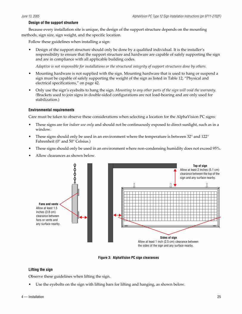
• Allow clearances as shown below.
Lifting the sign
Observe these guidelines when lifting the sign.
• Use the eyebolts on the sign with lifting bars for lifting and hanging, as shown below.
Fans and ventsAllow at least 1.5 inches (3.8 cm) clearance between fans or vents and any surface nearby.
Figure 3: AlphaVision PC sign clearances
Sides of signAllow at least 1 inch (2.5 cm) clearance between the sides of the sign and any surface nearby.
Top of signAllow at least 2 inches (5.1 cm) clearance between the top of the sign and any surface nearby.
June 13, 2005 AlphaVision PC Type 12 Sign Installation Instructions (pn 9711-2702F)
26 4 — Installation
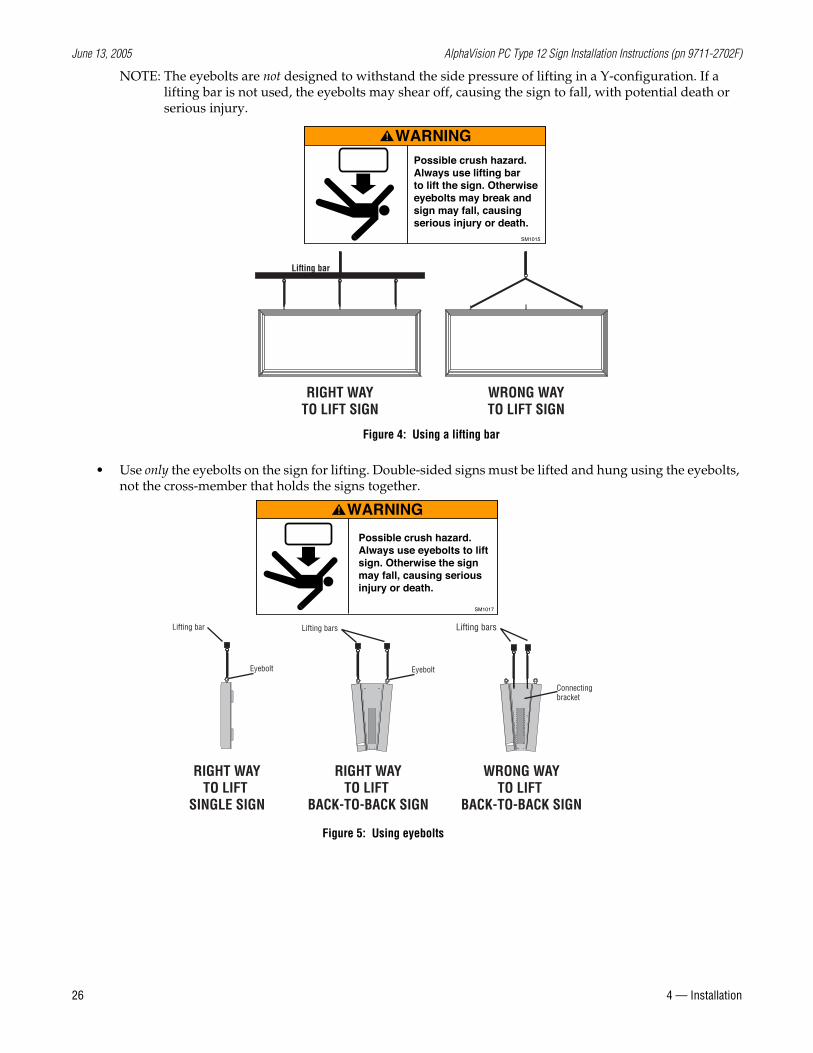
NOTE: The eyebolts are not designed to withstand the side pressure of lifting in a Y-configuration. If a lifting bar is not used, the eyebolts may shear off, causing the sign to fall, with potential death or serious injury.
• Use only the eyebolts on the sign for lifting. Double-sided signs must be lifted and hung using the eyebolts, not the cross-member that holds the signs together.
RIGHT WAYTO LIFT SIGN
Lifting bar
WRONG WAYTO LIFT SIGN
Figure 4: Using a lifting bar
Possible crush hazard.Always use lifting barto lift the sign. Otherwiseeyebolts may break andsign may fall, causingserious injury or death.
WARNING
SM1015
Lifting bars Lifting bars
RIGHT WAYTO LIFT
BACK-TO-BACK SIGN
WRONG WAYTO LIFT
BACK-TO-BACK SIGN
Eyebolt
Connectingbracket
RIGHT WAYTO LIFT
SINGLE SIGN
Eyebolt
Lifting bar
Possible crush hazard.Always use eyebolts to liftsign. Otherwise the sign may fall, causing serious injury or death.
WARNING
SM1017
Figure 5: Using eyebolts
June 13, 2005 AlphaVision PC Type 12 Sign Installation Instructions (pn 9711-2702F)
4 — Installation 27
Mounting the sign overhead
1. Disconnect all power from the sign at the power source(s) to prevent electrical injury or damage.
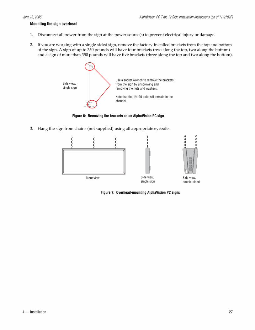
2. If you are working with a single-sided sign, remove the factory-installed brackets from the top and bottom of the sign. A sign of up to 350 pounds will have four brackets (two along the top, two along the bottom) and a sign of more than 350 pounds will have five brackets (three along the top and two along the bottom).
3. Hang the sign from chains (not supplied) using all appropriate eyebolts.
4.989.48
Use a socket wrench to remove the brackets from the sign by unscrewing andremoving the nuts and washers.
Note that the 1/4-20 bolts will remain in the channel.
Side view,single sign
Figure 6: Removing the brackets on an AlphaVision PC sign
Front view Side view,double-sided
Side view,single sign
Figure 7: Overhead-mounting AlphaVision PC signs
June 13, 2005 AlphaVision PC Type 12 Sign Installation Instructions (pn 9711-2702F)
28 4 — Installation
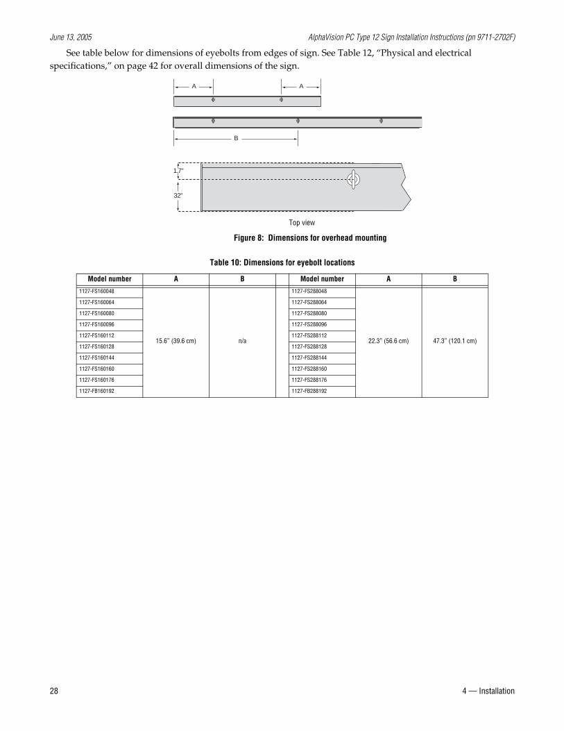
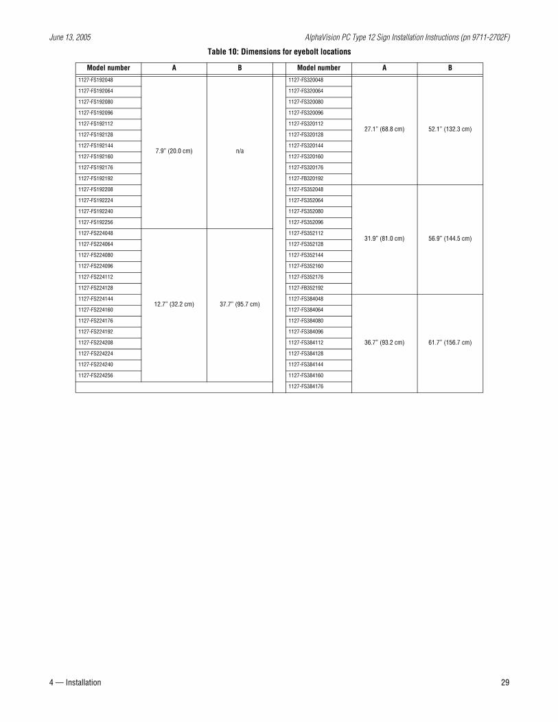
See table below for dimensions of eyebolts from edges of sign. See Table 12, “Physical and electrical specifications,” on page 42 for overall dimensions of the sign.
Table 10: Dimensions for eyebolt locations
Model number A B Model number A B
1127-FS160048
15.6” (39.6 cm) n/a
1127-FS288048
22.3” (56.6 cm) 47.3” (120.1 cm)
1127-FS160064 1127-FS288064
1127-FS160080 1127-FS288080
1127-FS160096 1127-FS288096
1127-FS160112 1127-FS288112
1127-FS160128 1127-FS288128
1127-FS160144 1127-FS288144
1127-FS160160 1127-FS288160
1127-FS160176 1127-FS288176
1127-FB160192 1127-FB288192
A A
B
32"
1.7"
Figure 8: Dimensions for overhead mounting
Top view
June 13, 2005 AlphaVision PC Type 12 Sign Installation Instructions (pn 9711-2702F)
4 — Installation 29
1127-FS192048
7.9” (20.0 cm) n/a
1127-FS320048
27.1” (68.8 cm) 52.1” (132.3 cm)
1127-FS192064 1127-FS320064
1127-FS192080 1127-FS320080
1127-FS192096 1127-FS320096
1127-FS192112 1127-FS320112
1127-FS192128 1127-FS320128
1127-FS192144 1127-FS320144
1127-FS192160 1127-FS320160
1127-FS192176 1127-FS320176
1127-FS192192 1127-FB320192
1127-FS192208 1127-FS352048
31.9” (81.0 cm) 56.9” (144.5 cm)
1127-FS192224 1127-FS352064
1127-FS192240 1127-FS352080
1127-FS192256 1127-FS352096
1127-FS224048
12.7” (32.2 cm) 37.7” (95.7 cm)
1127-FS352112
1127-FS224064 1127-FS352128
1127-FS224080 1127-FS352144
1127-FS224096 1127-FS352160
1127-FS224112 1127-FS352176
1127-FS224128 1127-FB352192
1127-FS224144 1127-FS384048
36.7” (93.2 cm) 61.7” (156.7 cm)
1127-FS224160 1127-FS384064
1127-FS224176 1127-FS384080
1127-FS224192 1127-FS384096
1127-FS224208 1127-FS384112
1127-FS224224 1127-FS384128
1127-FS224240 1127-FS384144
1127-FS224256 1127-FS384160
1127-FS384176
Table 10: Dimensions for eyebolt locations
Model number A B Model number A B
June 13, 2005 AlphaVision PC Type 12 Sign Installation Instructions (pn 9711-2702F)
30 4 — Installation
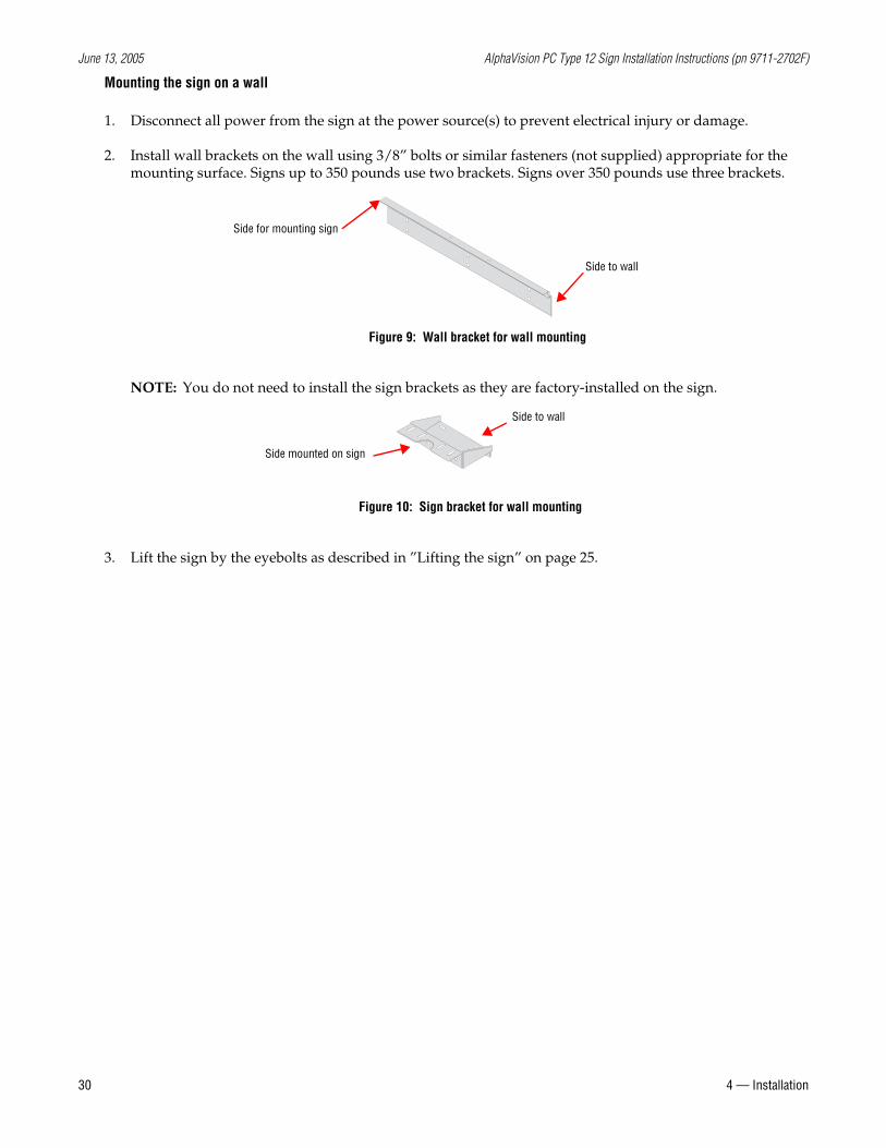
Mounting the sign on a wall
1. Disconnect all power from the sign at the power source(s) to prevent electrical injury or damage.
2. Install wall brackets on the wall using 3/8” bolts or similar fasteners (not supplied) appropriate for the mounting surface. Signs up to 350 pounds use two brackets. Signs over 350 pounds use three brackets.
NOTE: You do not need to install the sign brackets as they are factory-installed on the sign.
3. Lift the sign by the eyebolts as described in ”Lifting the sign” on page 25.
Figure 9: Wall bracket for wall mounting
Side to wall
Side for mounting sign
Figure 10: Sign bracket for wall mounting
Side to wall
Side mounted on sign
June 13, 2005 AlphaVision PC Type 12 Sign Installation Instructions (pn 9711-2702F)
4 — Installation 31
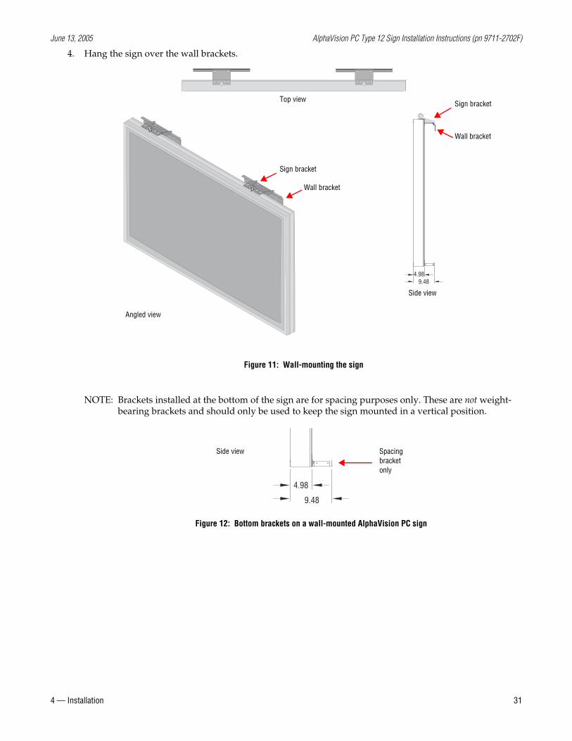
4. Hang the sign over the wall brackets.
NOTE: Brackets installed at the bottom of the sign are for spacing purposes only. These are not weight-bearing brackets and should only be used to keep the sign mounted in a vertical position.
Top view
Side view
Figure 11: Wall-mounting the sign
4.989.48
Angled view
Sign bracket
Wall bracket
Sign bracket
Wall bracket
4.98
9.48
Side view
Figure 12: Bottom brackets on a wall-mounted AlphaVision PC sign
Spacing bracket only
June 13, 2005 AlphaVision PC Type 12 Sign Installation Instructions (pn 9711-2702F)
32 4 — Installation
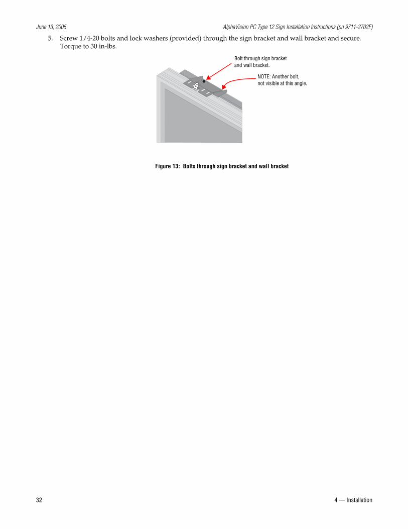
5. Screw 1/4-20 bolts and lock washers (provided) through the sign bracket and wall bracket and secure. Torque to 30 in-lbs.
Figure 13: Bolts through sign bracket and wall bracket
Bolt through sign bracket and wall bracket.
NOTE: Another bolt, not visible at this angle.
June 13, 2005 AlphaVision PC Type 12 Sign Installation Instructions (pn 9711-2702F)
4 — Installation 33
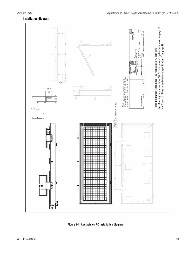
Installation diagram
21.0
0
2X2.
502X
8.00
02X
8.00
0
3X.5
5
3X1.
250
6X.3
97
.90
.75
2.503.25
1.27
Figure 14: AlphaVision PC Installation diagram
This
info
rmat
ion
is fo
r a 2
56 x
80
Alph
aVis
ion
PC s
ign
size
.Fo
r oth
er s
ign
size
s, s
ee T
able
10,
“Di
men
sion
s fo
r eye
bolt
loca
tions
,” o
n pa
ge 2
8an
d Ta
ble
12, “
Phys
ical
and
ele
ctric
al s
peci
ficat
ions
,” o
n pa
ge 4
2.
June 13, 2005 AlphaVision PC Type 12 Sign Installation Instructions (pn 9711-2702F)
34 4 — Installation
Electrical installation
Guidelines for electrical installation
NOTE: Electrical installation should only be attempted by a qualified electrician. Electrical connection must comply with all applicable national and local codes.
• A two-pole disconnect device must be installed in the building wiring for each branch circuit supplying the sign.
• Use minimum 176° F copper wire only. Torque terminals to 10-17 inch/pounds.
Utiliser uniquement un fil en cuivre pouvant supporter 80° C minimum. Serrer les bornes à 1,13 N/m – 1,92 N/m.
• Incoming power to a sign should be routed on a path separate from a sign’s serial communication wires. Do NOT run the power and serial communication wires in the same conduit.
• This sign should not be connected to a ground fault interrupt (GFI) circuit.
• Where power and serial communications wires must cross, the intersection should be perpendicular.
• Inspect all internal sign cabling for proper connection and seating.
• All electrical conduit and fittings must be metal and watertight.
• Each and every input terminal block should be protected by a circuit breaker as follows: •When one input terminal block is used, it should be protected by a 40-amp circuit breaker. •When two input terminal blocks are used, they should each be protected by a 30-amp circuit breaker.
• Before power is applied, the installer must verify ground continuity between the metal case and any ground terminal block where the building’s power connection is made.
• Electrical protection devices for signs with permanent connection using conduit and/or hard-wiring must include the following:
EnglishA readily-accessible disconnect device shall be installed in the fixed wiring supplying power to this
equipment. The disconnect device shall have a contact separation of at least 3 mm.This equipment relies on protective devices in the building installation for protection for short circuit
and/or overcurrent protection. Install this equipment only where these protective devices are present. The size and type of the protective devices shall be appropriate for the voltage and current ratings on this equipment.
FrançaisUn dispositif de déconnexion placé à un endroit pratique doit être installé sur le fil fixe qui alimente ce
matériel. La distance des contacts de ce dispositif de déconnexion doit être de 3 mm minimum.Ce matériel s’appuie sur des dispositifs de protection dans l’installation du bâtiment pour se protéger
des courts-circuits et/ou des surintensités. Installez ce matériel seulement là où de telles protections sont présentes. Le calibre et le type des protections doivent être adaptés à la tension et à l’intensité nominales du matériel.
DeutschIn der Festverdrahtung muß eine leicht zugängliche Trennvorrichtung installiert werden, die dieses
Gerät mit Strom versorgt. Die Trennvorrichtung muß eine Kontakttrennung von mindestens 3 mm aufweisen.
Kurzschlußschutz und/oder Überstromschutz wird in diesem Gerät durch entsprechende Schutzvorrichtungen in der Gebäudeinstallation gewährleistet. Dieses Gerät nur dort installieren, wo diese Schutzvorrichtungen vorhanden sind. Größe und Art der Schutzvorrichtungen müssen den Spannungs- und Stromnennstärken dieses Geräts entsprechen.
ItalianoUn dispositivo di sconnessione prontamente accessibile dovrà essere installato nel cablaggio fissato
June 13, 2005 AlphaVision PC Type 12 Sign Installation Instructions (pn 9711-2702F)
4 — Installation 35
che fornisce corrente alla presente apparecchiatura. Il dispositivo di sconnessione dovrà avere una separazione di contatto di almeno 3 mm.
La presente apparecchiatura si affida a dispositivi di protezione nell’installazione da edificio per protezione da corto circuito e/o protezione da sovracorrente. Installare l’apparecchiatura solamente in punti dove sono presenti questi dispositivi di protezione. Le dimensioni e il tipo di dispositivo di protezione dovranno essere appropriati alla tensione e ai valori di corrente della presente apparecchiatura.
EspañolSe debe instalar en el cableado fijo que alimenta este equipo un dispositivo de desconexión fácilmente
accesible. Dicho dispositivo tendrá una separación entre contactos de por lo menos 3 mm.Este equipo depende del uso de dispositivos protectores en la instalación del edificio para protección
en caso de cortocircuito y/o protección contra sobreintensidad. Instale este equipo únicamente en caso de disponer de dispositivos protectores. El tipo y tamaño de los dispositivos protectores deberán ser adecuados para los valores nominales de tensión y corriente de este equipo.
June 13, 2005 AlphaVision PC Type 12 Sign Installation Instructions (pn 9711-2702F)
36 4 — Installation
Opening the sign
To facilitate this process, one person at each side of the sign is recommended.
1. Disconnect all power from the sign at the power source(s).
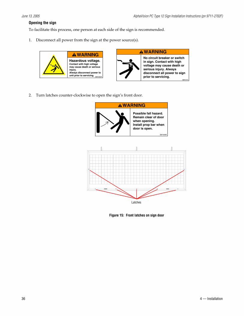
2. Turn latches counter-clockwise to open the sign’s front door.
Contact with high voltagemay cause death or seriousinjury.Always disconnect power to unit prior to servicing.
Hazardous voltage.
WARNING
SM1000A
No circuit breaker or switch in sign. Contact with high voltage may cause death or serious injury. Always disconnect all power to sign prior to servicing.
WARNING
SM1010
WARNING
Possible fall hazard. Remain clear of doorwhen opening.Install prop bar whendoor is open.
SM1005B
Latches
Figure 15: Front latches on sign door
June 13, 2005 AlphaVision PC Type 12 Sign Installation Instructions (pn 9711-2702F)
4 — Installation 37
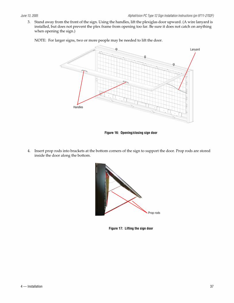
3. Stand away from the front of the sign. Using the handles, lift the plexiglas door upward. (A wire lanyard is installed, but does not prevent the plex frame from opening too far. Be sure it does not catch on anything when opening the sign.)
NOTE: For larger signs, two or more people may be needed to lift the door.
4. Insert prop rods into brackets at the bottom corners of the sign to support the door. Prop rods are stored inside the door along the bottom.
Figure 16: Opening/closing sign door
Lanyard
Handles
Figure 17: Lifting the sign door
Prop rods
June 13, 2005 AlphaVision PC Type 12 Sign Installation Instructions (pn 9711-2702F)
38 4 — Installation
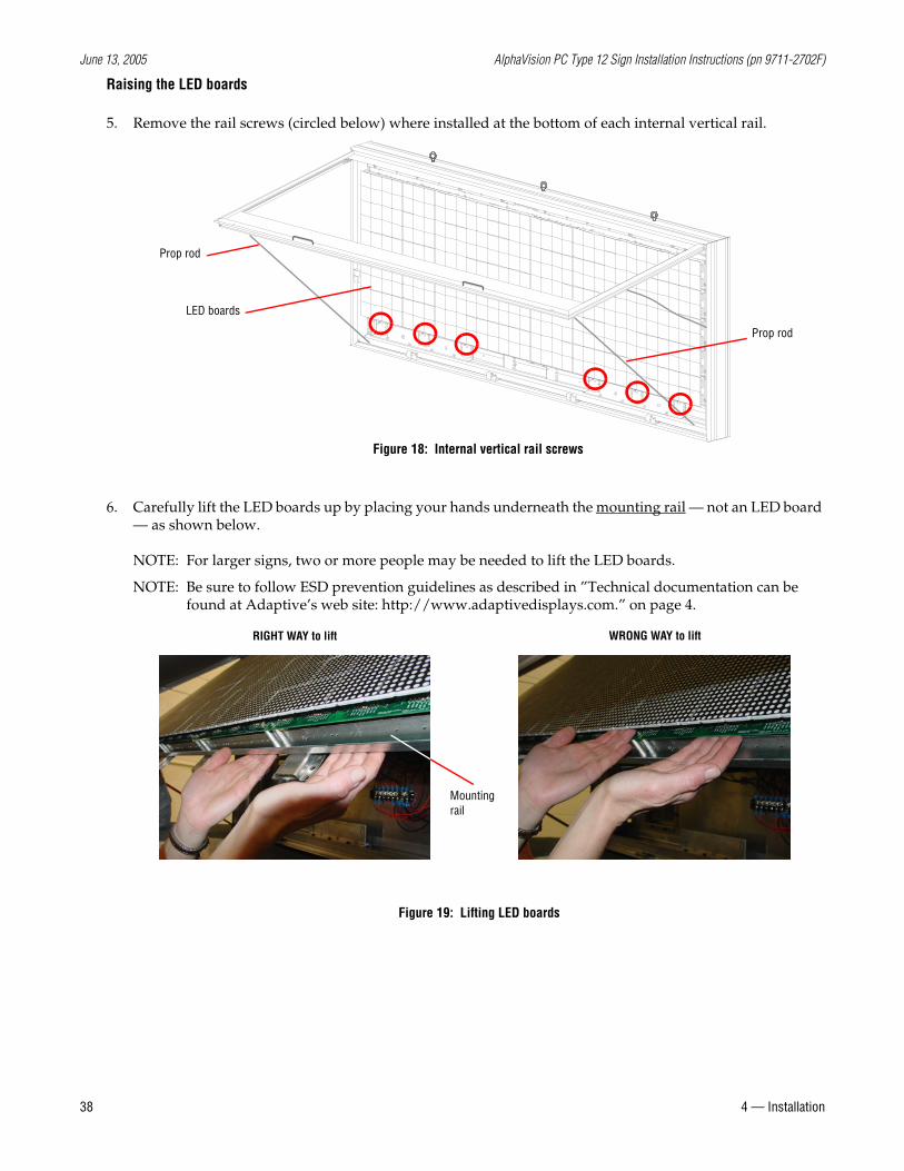
Raising the LED boards
5. Remove the rail screws (circled below) where installed at the bottom of each internal vertical rail.
6. Carefully lift the LED boards up by placing your hands underneath the mounting rail — not an LED board — as shown below.
NOTE: For larger signs, two or more people may be needed to lift the LED boards.
NOTE: Be sure to follow ESD prevention guidelines as described in ”Technical documentation can be found at Adaptive’s web site: http://www.adaptivedisplays.com.” on page 4.
LED boards
Figure 18: Internal vertical rail screws
Prop rod
Prop rod
RIGHT WAY to lift WRONG WAY to lift
Figure 19: Lifting LED boards
Mounting rail
June 13, 2005 AlphaVision PC Type 12 Sign Installation Instructions (pn 9711-2702F)
4 — Installation 39
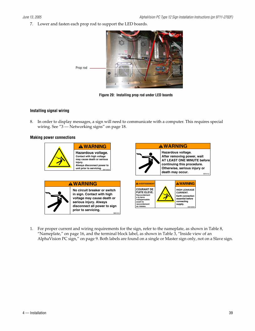
7. Lower and fasten each prop rod to support the LED boards.
Installing signal wiring
8. In order to display messages, a sign will need to communicate with a computer. This requires special wiring. See ”3 — Networking signs” on page 18.
Making power connections
1. For proper current and wiring requirements for the sign, refer to the nameplate, as shown in Table 8, “Nameplate,” on page 16, and the terminal block label, as shown in Table 3, “Inside view of an AlphaVision PC sign,” on page 9. Both labels are found on a single or Master sign only, not on a Slave sign.
Prop rod
Figure 20: Installing prop rod under LED boards
Contact with high voltagemay cause death or seriousinjury.Always disconnect power to unit prior to servicing.
Hazardous voltage.
WARNING
SM1000A
No circuit breaker or switch in sign. Contact with high voltage may cause death or serious injury. Always disconnect all power to sign prior to servicing.
WARNING
SM1010
WARNINGHazardous voltage. After removing power, waitAT LEAST ONE MINUTE beforecontinuing this procedure.Otherwise, serious injury ordeath may occur.
SM1012
HIGH LEAKAGECURRENT.
COURANT DEFUITE ELEVE.
Earth connectionessential beforeconnectingsupply.
Raccordementa la terreindispensableavant leraccordementau reseau.
AVERTISSEMENT WARNING
SM1009A
June 13, 2005 AlphaVision PC Type 12 Sign Installation Instructions (pn 9711-2702F)
40 4 — Installation
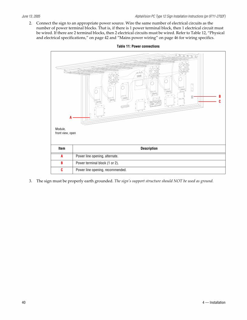
2. Connect the sign to an appropriate power source. Wire the same number of electrical circuits as the number of power terminal blocks. That is, if there is 1 power terminal block, then 1 electrical circuit must be wired. If there are 2 terminal blocks, then 2 electrical circuits must be wired. Refer to Table 12, “Physical and electrical specifications,” on page 42 and ”Mains power wiring” on page 46 for wiring specifics.
3. The sign must be properly earth grounded. The sign’s support structure should NOT be used as ground.
Table 11: Power connections
Item Description
A Power line opening, alternate.
B Power terminal block (1 or 2).
C Power line opening, recommended.
Module, front view, open
BC
A
June 13, 2005 AlphaVision PC Type 12 Sign Installation Instructions (pn 9711-2702F)
4 — Installation 41
Closing the sign
To facilitate this process, one person at each side of the sign is recommended.
4. Raise each prop rod for the LED boards and fasten under the LED boards. See Figure 20, “Installing prop rod under LED boards” above.
5. Lower the LED boards. See Figure 19, “Lifting LED boards,” on page 38.
6. Refasten screws to the internal vertical rails. See Figure 18, “Internal vertical rail screws,” on page 38.
7. Raise each prop rod for the door and fasten under the door. See Figure 17, “Lifting the sign door,” on page 37.
8. Lower the door. Be sure the wire lanyards do not get caught when closing the door.
9. Use the quarter-turn latches to close the sign’s door. See Figure 15, “Front latches on sign door,” on page 36.
Testing the installation
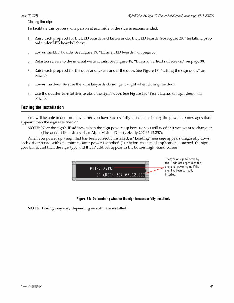
You will be able to determine whether you have successfully installed a sign by the power-up messages that appear when the sign is turned on.
NOTE: Note the sign’s IP address when the sign powers up because you will need it if you want to change it. (The default IP address of an AlphaVision PC is typically 207.67.12.237).
When you power up a sign that has been correctly installed, a “Loading” message appears diagonally down each driver board with one minutes after power is applied. Just before the actual application is started, the sign goes blank and then the sign type and the IP address appear in the bottom right-hand corner:
NOTE: Timing may vary depending on software installed.
IP ADDR: 207.67.12.237P1127 AVPC
Figure 21: Determining whether the sign is successfully installed.
The type of sign followed by the IP address appears on the sign after powering up if the sign has been correctly installed.
June 13, 2005 AlphaVision PC Type 12 Sign Installation Instructions (pn 9711-2702F)
42 9— Appendices
9— Appendices
Technical specifications
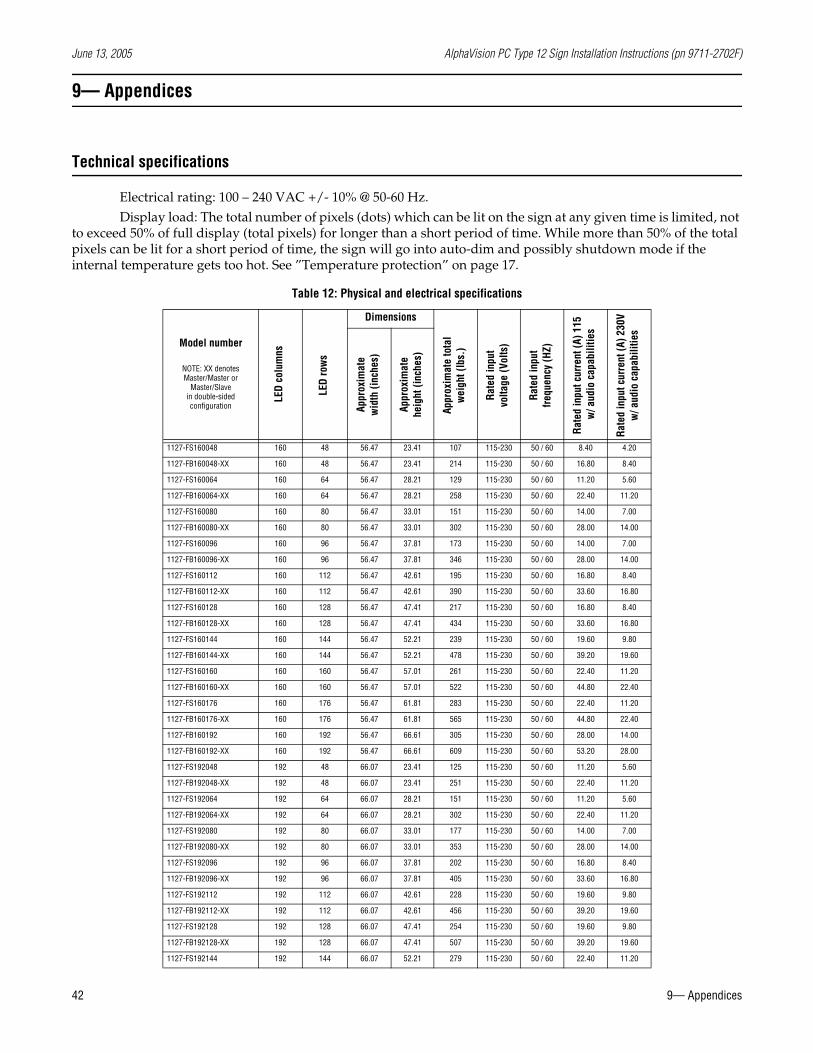
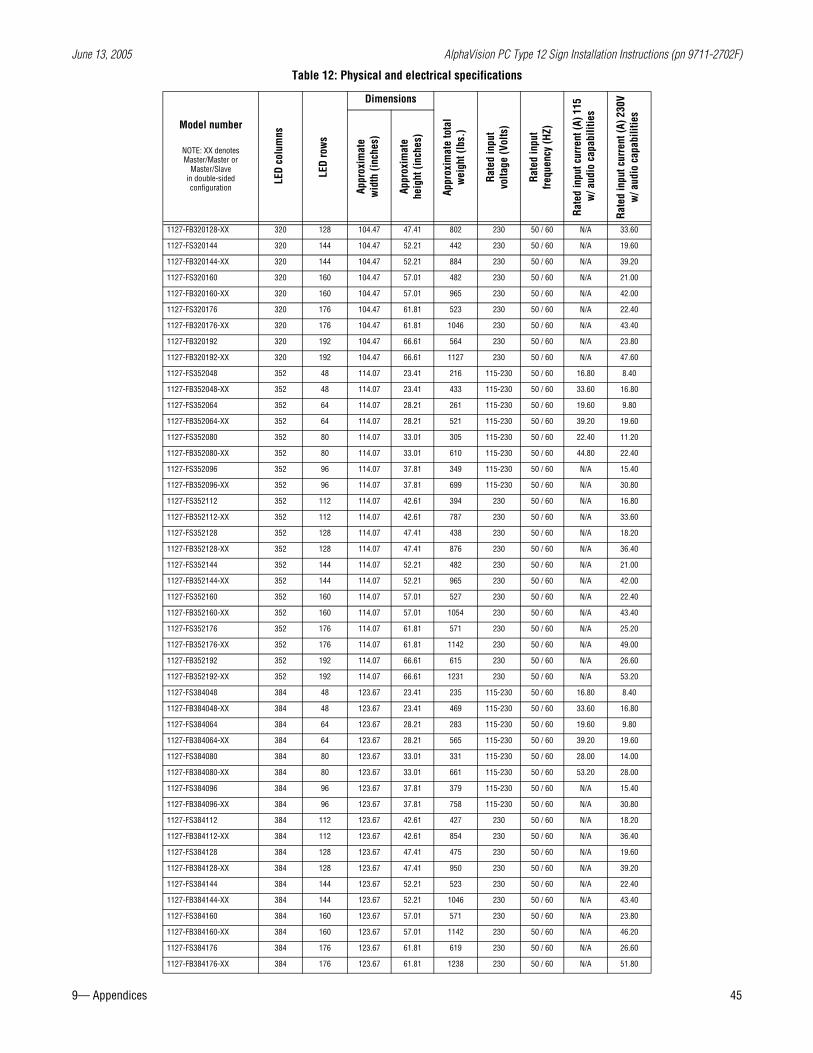
Electrical rating: 100 – 240 VAC +/- 10% @ 50-60 Hz.Display load: The total number of pixels (dots) which can be lit on the sign at any given time is limited, not
to exceed 50% of full display (total pixels) for longer than a short period of time. While more than 50% of the total pixels can be lit for a short period of time, the sign will go into auto-dim and possibly shutdown mode if the internal temperature gets too hot. See ”Temperature protection” on page 17.
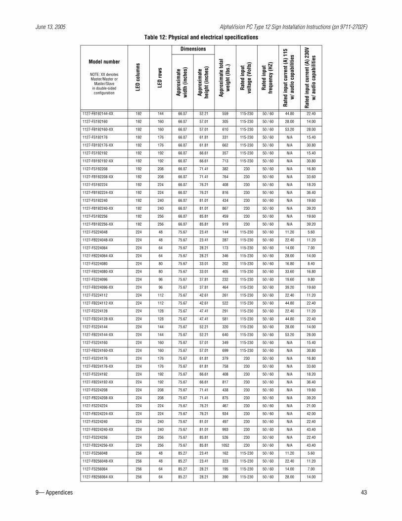
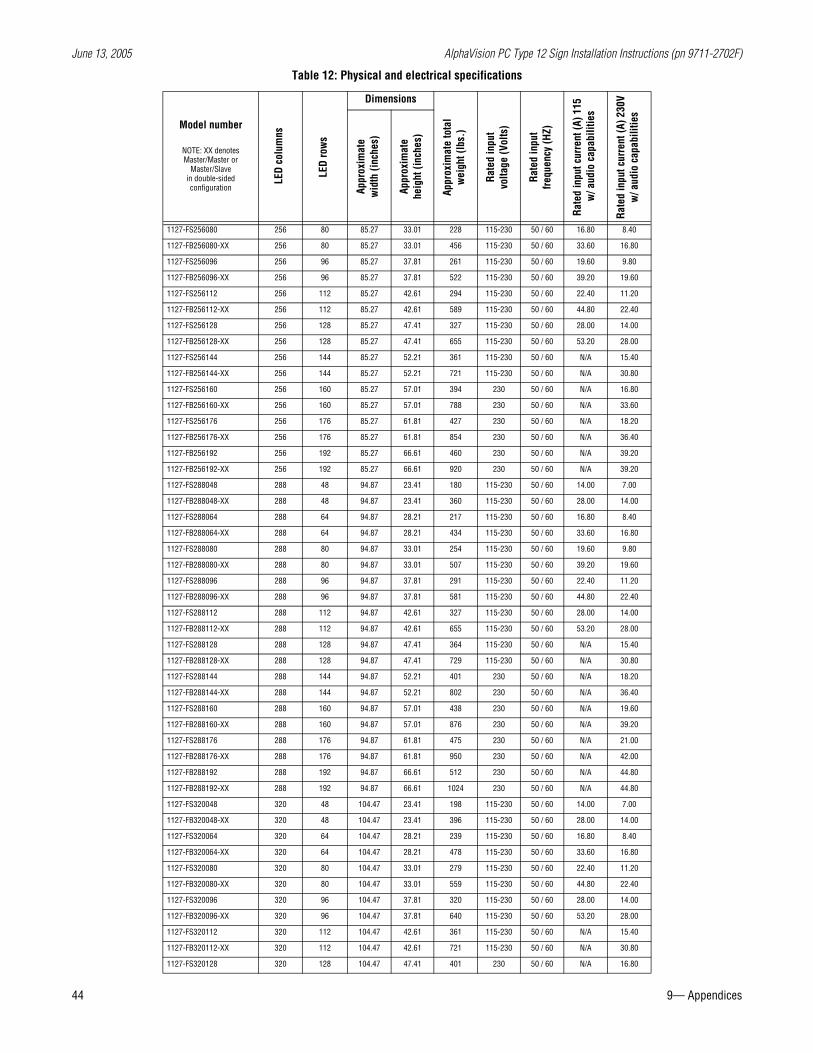
Table 12: Physical and electrical specifications
Model number
NOTE: XX denotes Master/Master or
Master/Slave in double-sided configuration L
ED c
olum
ns
LED
row
sDimensions
Appr
oxim
ate
tota
lw
eigh
t (lb
s.)
Rate
d in
put
volta
ge (V
olts
)
Rate
d in
put
frequ
ency
(HZ)
Rate
d in
put c
urre
nt (A
) 115
w/ a
udio
cap
abili
ties
Rate
d in
put c
urre
nt (A
) 230
Vw
/ aud
io c
apab
ilitie
s
Appr
oxim
ate
wid
th (i
nche
s)
Appr
oxim
ate
heig
ht (i
nche
s)
1127-FS160048 160 48 56.47 23.41 107 115-230 50 / 60 8.40 4.20
1127-FB160048-XX 160 48 56.47 23.41 214 115-230 50 / 60 16.80 8.40
1127-FS160064 160 64 56.47 28.21 129 115-230 50 / 60 11.20 5.60
1127-FB160064-XX 160 64 56.47 28.21 258 115-230 50 / 60 22.40 11.20
1127-FS160080 160 80 56.47 33.01 151 115-230 50 / 60 14.00 7.00
1127-FB160080-XX 160 80 56.47 33.01 302 115-230 50 / 60 28.00 14.00
1127-FS160096 160 96 56.47 37.81 173 115-230 50 / 60 14.00 7.00
1127-FB160096-XX 160 96 56.47 37.81 346 115-230 50 / 60 28.00 14.00
1127-FS160112 160 112 56.47 42.61 195 115-230 50 / 60 16.80 8.40
1127-FB160112-XX 160 112 56.47 42.61 390 115-230 50 / 60 33.60 16.80
1127-FS160128 160 128 56.47 47.41 217 115-230 50 / 60 16.80 8.40
1127-FB160128-XX 160 128 56.47 47.41 434 115-230 50 / 60 33.60 16.80
1127-FS160144 160 144 56.47 52.21 239 115-230 50 / 60 19.60 9.80
1127-FB160144-XX 160 144 56.47 52.21 478 115-230 50 / 60 39.20 19.60
1127-FS160160 160 160 56.47 57.01 261 115-230 50 / 60 22.40 11.20
1127-FB160160-XX 160 160 56.47 57.01 522 115-230 50 / 60 44.80 22.40
1127-FS160176 160 176 56.47 61.81 283 115-230 50 / 60 22.40 11.20
1127-FB160176-XX 160 176 56.47 61.81 565 115-230 50 / 60 44.80 22.40
1127-FB160192 160 192 56.47 66.61 305 115-230 50 / 60 28.00 14.00
1127-FB160192-XX 160 192 56.47 66.61 609 115-230 50 / 60 53.20 28.00
1127-FS192048 192 48 66.07 23.41 125 115-230 50 / 60 11.20 5.60
1127-FB192048-XX 192 48 66.07 23.41 251 115-230 50 / 60 22.40 11.20
1127-FS192064 192 64 66.07 28.21 151 115-230 50 / 60 11.20 5.60
1127-FB192064-XX 192 64 66.07 28.21 302 115-230 50 / 60 22.40 11.20
1127-FS192080 192 80 66.07 33.01 177 115-230 50 / 60 14.00 7.00
1127-FB192080-XX 192 80 66.07 33.01 353 115-230 50 / 60 28.00 14.00
1127-FS192096 192 96 66.07 37.81 202 115-230 50 / 60 16.80 8.40
1127-FB192096-XX 192 96 66.07 37.81 405 115-230 50 / 60 33.60 16.80
1127-FS192112 192 112 66.07 42.61 228 115-230 50 / 60 19.60 9.80
1127-FB192112-XX 192 112 66.07 42.61 456 115-230 50 / 60 39.20 19.60
1127-FS192128 192 128 66.07 47.41 254 115-230 50 / 60 19.60 9.80
1127-FB192128-XX 192 128 66.07 47.41 507 115-230 50 / 60 39.20 19.60
1127-FS192144 192 144 66.07 52.21 279 115-230 50 / 60 22.40 11.20
June 13, 2005 AlphaVision PC Type 12 Sign Installation Instructions (pn 9711-2702F)
9— Appendices 43
1127-FB192144-XX 192 144 66.07 52.21 559 115-230 50 / 60 44.80 22.40
1127-FS192160 192 160 66.07 57.01 305 115-230 50 / 60 28.00 14.00
1127-FB192160-XX 192 160 66.07 57.01 610 115-230 50 / 60 53.20 28.00
1127-FS192176 192 176 66.07 61.81 331 115-230 50 / 60 N/A 15.40
1127-FB192176-XX 192 176 66.07 61.81 662 115-230 50 / 60 N/A 30.80
1127-FS192192 192 192 66.07 66.61 357 115-230 50 / 60 N/A 15.40
1127-FB192192-XX 192 192 66.07 66.61 713 115-230 50 / 60 N/A 30.80
1127-FS192208 192 208 66.07 71.41 382 230 50 / 60 N/A 16.80
1127-FB192208-XX 192 208 66.07 71.41 764 230 50 / 60 N/A 33.60
1127-FS192224 192 224 66.07 76.21 408 230 50 / 60 N/A 18.20
1127-FB192224-XX 192 224 66.07 76.21 816 230 50 / 60 N/A 36.40
1127-FS192240 192 240 66.07 81.01 434 230 50 / 60 N/A 19.60
1127-FB192240-XX 192 240 66.07 81.01 867 230 50 / 60 N/A 39.20
1127-FS192256 192 256 66.07 85.81 459 230 50 / 60 N/A 19.60
1127-FB192256-XX 192 256 66.07 85.81 919 230 50 / 60 N/A 39.20
1127-FS224048 224 48 75.67 23.41 144 115-230 50 / 60 11.20 5.60
1127-FB224048-XX 224 48 75.67 23.41 287 115-230 50 / 60 22.40 11.20
1127-FS224064 224 64 75.67 28.21 173 115-230 50 / 60 14.00 7.00
1127-FB224064-XX 224 64 75.67 28.21 346 115-230 50 / 60 28.00 14.00
1127-FS224080 224 80 75.67 33.01 202 115-230 50 / 60 16.80 8.40
1127-FB224080-XX 224 80 75.67 33.01 405 115-230 50 / 60 33.60 16.80
1127-FS224096 224 96 75.67 37.81 232 115-230 50 / 60 19.60 9.80
1127-FB224096-XX 224 96 75.67 37.81 464 115-230 50 / 60 39.20 19.60
1127-FS224112 224 112 75.67 42.61 261 115-230 50 / 60 22.40 11.20
1127-FB224112-XX 224 112 75.67 42.61 522 115-230 50 / 60 44.80 22.40
1127-FS224128 224 128 75.67 47.41 291 115-230 50 / 60 22.40 11.20
1127-FB224128-XX 224 128 75.67 47.41 581 115-230 50 / 60 44.80 22.40
1127-FS224144 224 144 75.67 52.21 320 115-230 50 / 60 28.00 14.00
1127-FB224144-XX 224 144 75.67 52.21 640 115-230 50 / 60 53.20 28.00
1127-FS224160 224 160 75.67 57.01 349 115-230 50 / 60 N/A 15.40
1127-FB224160-XX 224 160 75.67 57.01 699 115-230 50 / 60 N/A 30.80
1127-FS224176 224 176 75.67 61.81 379 230 50 / 60 N/A 16.80
1127-FB224176-XX 224 176 75.67 61.81 758 230 50 / 60 N/A 33.60
1127-FS224192 224 192 75.67 66.61 408 230 50 / 60 N/A 18.20
1127-FB224192-XX 224 192 75.67 66.61 817 230 50 / 60 N/A 36.40
1127-FS224208 224 208 75.67 71.41 438 230 50 / 60 N/A 19.60
1127-FB224208-XX 224 208 75.67 71.41 875 230 50 / 60 N/A 39.20
1127-FS224224 224 224 75.67 76.21 467 230 50 / 60 N/A 21.00
1127-FB224224-XX 224 224 75.67 76.21 934 230 50 / 60 N/A 42.00
1127-FS224240 224 240 75.67 81.01 497 230 50 / 60 N/A 22.40
1127-FB224240-XX 224 240 75.67 81.01 993 230 50 / 60 N/A 43.40
1127-FS224256 224 256 75.67 85.81 526 230 50 / 60 N/A 22.40
1127-FB224256-XX 224 256 75.67 85.81 1052 230 50 / 60 N/A 43.40
1127-FS256048 256 48 85.27 23.41 162 115-230 50 / 60 11.20 5.60
1127-FB256048-XX 256 48 85.27 23.41 323 115-230 50 / 60 22.40 11.20
1127-FS256064 256 64 85.27 28.21 195 115-230 50 / 60 14.00 7.00
1127-FB256064-XX 256 64 85.27 28.21 390 115-230 50 / 60 28.00 14.00
Table 12: Physical and electrical specifications
Model number
NOTE: XX denotes Master/Master or
Master/Slave in double-sided configuration L
ED c
olum
ns
LED
row
s
Dimensions
Appr
oxim
ate
tota
lw
eigh
t (lb
s.)
Rate
d in
put
volta
ge (V
olts
)
Rate
d in
put
frequ
ency
(HZ)
Rate
d in
put c
urre
nt (A
) 115
w/ a
udio
cap
abili
ties
Rate
d in
put c
urre
nt (A
) 230
Vw
/ aud
io c
apab
ilitie
s
Appr
oxim
ate
wid
th (i
nche
s)
Appr
oxim
ate
heig
ht (i
nche
s)
June 13, 2005 AlphaVision PC Type 12 Sign Installation Instructions (pn 9711-2702F)
44 9— Appendices
1127-FS256080 256 80 85.27 33.01 228 115-230 50 / 60 16.80 8.40
1127-FB256080-XX 256 80 85.27 33.01 456 115-230 50 / 60 33.60 16.80
1127-FS256096 256 96 85.27 37.81 261 115-230 50 / 60 19.60 9.80
1127-FB256096-XX 256 96 85.27 37.81 522 115-230 50 / 60 39.20 19.60
1127-FS256112 256 112 85.27 42.61 294 115-230 50 / 60 22.40 11.20
1127-FB256112-XX 256 112 85.27 42.61 589 115-230 50 / 60 44.80 22.40
1127-FS256128 256 128 85.27 47.41 327 115-230 50 / 60 28.00 14.00
1127-FB256128-XX 256 128 85.27 47.41 655 115-230 50 / 60 53.20 28.00
1127-FS256144 256 144 85.27 52.21 361 115-230 50 / 60 N/A 15.40
1127-FB256144-XX 256 144 85.27 52.21 721 115-230 50 / 60 N/A 30.80
1127-FS256160 256 160 85.27 57.01 394 230 50 / 60 N/A 16.80
1127-FB256160-XX 256 160 85.27 57.01 788 230 50 / 60 N/A 33.60
1127-FS256176 256 176 85.27 61.81 427 230 50 / 60 N/A 18.20
1127-FB256176-XX 256 176 85.27 61.81 854 230 50 / 60 N/A 36.40
1127-FB256192 256 192 85.27 66.61 460 230 50 / 60 N/A 39.20
1127-FB256192-XX 256 192 85.27 66.61 920 230 50 / 60 N/A 39.20
1127-FS288048 288 48 94.87 23.41 180 115-230 50 / 60 14.00 7.00
1127-FB288048-XX 288 48 94.87 23.41 360 115-230 50 / 60 28.00 14.00
1127-FS288064 288 64 94.87 28.21 217 115-230 50 / 60 16.80 8.40
1127-FB288064-XX 288 64 94.87 28.21 434 115-230 50 / 60 33.60 16.80
1127-FS288080 288 80 94.87 33.01 254 115-230 50 / 60 19.60 9.80
1127-FB288080-XX 288 80 94.87 33.01 507 115-230 50 / 60 39.20 19.60
1127-FS288096 288 96 94.87 37.81 291 115-230 50 / 60 22.40 11.20
1127-FB288096-XX 288 96 94.87 37.81 581 115-230 50 / 60 44.80 22.40
1127-FS288112 288 112 94.87 42.61 327 115-230 50 / 60 28.00 14.00
1127-FB288112-XX 288 112 94.87 42.61 655 115-230 50 / 60 53.20 28.00
1127-FS288128 288 128 94.87 47.41 364 115-230 50 / 60 N/A 15.40
1127-FB288128-XX 288 128 94.87 47.41 729 115-230 50 / 60 N/A 30.80
1127-FS288144 288 144 94.87 52.21 401 230 50 / 60 N/A 18.20
1127-FB288144-XX 288 144 94.87 52.21 802 230 50 / 60 N/A 36.40
1127-FS288160 288 160 94.87 57.01 438 230 50 / 60 N/A 19.60
1127-FB288160-XX 288 160 94.87 57.01 876 230 50 / 60 N/A 39.20
1127-FS288176 288 176 94.87 61.81 475 230 50 / 60 N/A 21.00
1127-FB288176-XX 288 176 94.87 61.81 950 230 50 / 60 N/A 42.00
1127-FB288192 288 192 94.87 66.61 512 230 50 / 60 N/A 44.80
1127-FB288192-XX 288 192 94.87 66.61 1024 230 50 / 60 N/A 44.80
1127-FS320048 320 48 104.47 23.41 198 115-230 50 / 60 14.00 7.00
1127-FB320048-XX 320 48 104.47 23.41 396 115-230 50 / 60 28.00 14.00
1127-FS320064 320 64 104.47 28.21 239 115-230 50 / 60 16.80 8.40
1127-FB320064-XX 320 64 104.47 28.21 478 115-230 50 / 60 33.60 16.80
1127-FS320080 320 80 104.47 33.01 279 115-230 50 / 60 22.40 11.20
1127-FB320080-XX 320 80 104.47 33.01 559 115-230 50 / 60 44.80 22.40
1127-FS320096 320 96 104.47 37.81 320 115-230 50 / 60 28.00 14.00
1127-FB320096-XX 320 96 104.47 37.81 640 115-230 50 / 60 53.20 28.00
1127-FS320112 320 112 104.47 42.61 361 115-230 50 / 60 N/A 15.40
1127-FB320112-XX 320 112 104.47 42.61 721 115-230 50 / 60 N/A 30.80
1127-FS320128 320 128 104.47 47.41 401 230 50 / 60 N/A 16.80
Table 12: Physical and electrical specifications
Model number
NOTE: XX denotes Master/Master or
Master/Slave in double-sided configuration L
ED c
olum
ns
LED
row
s
Dimensions
Appr
oxim
ate
tota
lw
eigh
t (lb
s.)
Rate
d in
put
volta
ge (V
olts
)
Rate
d in
put
frequ
ency
(HZ)
Rate
d in
put c
urre
nt (A
) 115
w/ a
udio
cap
abili
ties
Rate
d in
put c
urre
nt (A
) 230
Vw
/ aud
io c
apab
ilitie
s
Appr
oxim
ate
wid
th (i
nche
s)
Appr
oxim
ate
heig
ht (i
nche
s)
June 13, 2005 AlphaVision PC Type 12 Sign Installation Instructions (pn 9711-2702F)
9— Appendices 45
1127-FB320128-XX 320 128 104.47 47.41 802 230 50 / 60 N/A 33.60
1127-FS320144 320 144 104.47 52.21 442 230 50 / 60 N/A 19.60
1127-FB320144-XX 320 144 104.47 52.21 884 230 50 / 60 N/A 39.20
1127-FS320160 320 160 104.47 57.01 482 230 50 / 60 N/A 21.00
1127-FB320160-XX 320 160 104.47 57.01 965 230 50 / 60 N/A 42.00
1127-FS320176 320 176 104.47 61.81 523 230 50 / 60 N/A 22.40
1127-FB320176-XX 320 176 104.47 61.81 1046 230 50 / 60 N/A 43.40
1127-FB320192 320 192 104.47 66.61 564 230 50 / 60 N/A 23.80
1127-FB320192-XX 320 192 104.47 66.61 1127 230 50 / 60 N/A 47.60
1127-FS352048 352 48 114.07 23.41 216 115-230 50 / 60 16.80 8.40
1127-FB352048-XX 352 48 114.07 23.41 433 115-230 50 / 60 33.60 16.80
1127-FS352064 352 64 114.07 28.21 261 115-230 50 / 60 19.60 9.80
1127-FB352064-XX 352 64 114.07 28.21 521 115-230 50 / 60 39.20 19.60
1127-FS352080 352 80 114.07 33.01 305 115-230 50 / 60 22.40 11.20
1127-FB352080-XX 352 80 114.07 33.01 610 115-230 50 / 60 44.80 22.40
1127-FS352096 352 96 114.07 37.81 349 115-230 50 / 60 N/A 15.40
1127-FB352096-XX 352 96 114.07 37.81 699 115-230 50 / 60 N/A 30.80
1127-FS352112 352 112 114.07 42.61 394 230 50 / 60 N/A 16.80
1127-FB352112-XX 352 112 114.07 42.61 787 230 50 / 60 N/A 33.60
1127-FS352128 352 128 114.07 47.41 438 230 50 / 60 N/A 18.20
1127-FB352128-XX 352 128 114.07 47.41 876 230 50 / 60 N/A 36.40
1127-FS352144 352 144 114.07 52.21 482 230 50 / 60 N/A 21.00
1127-FB352144-XX 352 144 114.07 52.21 965 230 50 / 60 N/A 42.00
1127-FS352160 352 160 114.07 57.01 527 230 50 / 60 N/A 22.40
1127-FB352160-XX 352 160 114.07 57.01 1054 230 50 / 60 N/A 43.40
1127-FS352176 352 176 114.07 61.81 571 230 50 / 60 N/A 25.20
1127-FB352176-XX 352 176 114.07 61.81 1142 230 50 / 60 N/A 49.00
1127-FB352192 352 192 114.07 66.61 615 230 50 / 60 N/A 26.60
1127-FB352192-XX 352 192 114.07 66.61 1231 230 50 / 60 N/A 53.20
1127-FS384048 384 48 123.67 23.41 235 115-230 50 / 60 16.80 8.40
1127-FB384048-XX 384 48 123.67 23.41 469 115-230 50 / 60 33.60 16.80
1127-FS384064 384 64 123.67 28.21 283 115-230 50 / 60 19.60 9.80
1127-FB384064-XX 384 64 123.67 28.21 565 115-230 50 / 60 39.20 19.60
1127-FS384080 384 80 123.67 33.01 331 115-230 50 / 60 28.00 14.00
1127-FB384080-XX 384 80 123.67 33.01 661 115-230 50 / 60 53.20 28.00
1127-FS384096 384 96 123.67 37.81 379 115-230 50 / 60 N/A 15.40
1127-FB384096-XX 384 96 123.67 37.81 758 115-230 50 / 60 N/A 30.80
1127-FS384112 384 112 123.67 42.61 427 230 50 / 60 N/A 18.20
1127-FB384112-XX 384 112 123.67 42.61 854 230 50 / 60 N/A 36.40
1127-FS384128 384 128 123.67 47.41 475 230 50 / 60 N/A 19.60
1127-FB384128-XX 384 128 123.67 47.41 950 230 50 / 60 N/A 39.20
1127-FS384144 384 144 123.67 52.21 523 230 50 / 60 N/A 22.40
1127-FB384144-XX 384 144 123.67 52.21 1046 230 50 / 60 N/A 43.40
1127-FS384160 384 160 123.67 57.01 571 230 50 / 60 N/A 23.80
1127-FB384160-XX 384 160 123.67 57.01 1142 230 50 / 60 N/A 46.20
1127-FS384176 384 176 123.67 61.81 619 230 50 / 60 N/A 26.60
1127-FB384176-XX 384 176 123.67 61.81 1238 230 50 / 60 N/A 51.80
Table 12: Physical and electrical specifications
Model number
NOTE: XX denotes Master/Master or
Master/Slave in double-sided configuration L
ED c
olum
ns
LED
row
s
Dimensions
Appr
oxim
ate
tota
lw
eigh
t (lb
s.)
Rate
d in
put
volta
ge (V
olts
)
Rate
d in
put
frequ
ency
(HZ)
Rate
d in
put c
urre
nt (A
) 115
w/ a
udio
cap
abili
ties
Rate
d in
put c
urre
nt (A
) 230
Vw
/ aud
io c
apab
ilitie
s
Appr
oxim
ate
wid
th (i
nche
s)
Appr
oxim
ate
heig
ht (i
nche
s)
June 13, 2005 AlphaVision PC Type 12 Sign Installation Instructions (pn 9711-2702F)
46 9— Appendices
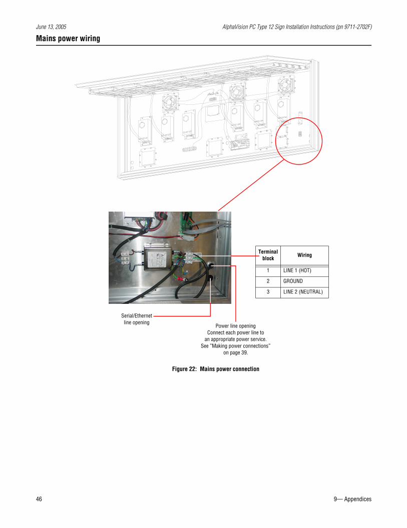
Mains power wiring
Terminal block
Wiring
1 LINE 1 (HOT)
2 GROUND
3 LINE 2 (NEUTRAL)
Power line openingConnect each power line to
an appropriate power service.See ”Making power connections”
on page 39.
Serial/Ethernet line opening
Figure 22: Mains power connection
June 13, 2005 AlphaVision PC Type 12 Sign Installation Instructions (pn 9711-2702F)
9— Appendices 47
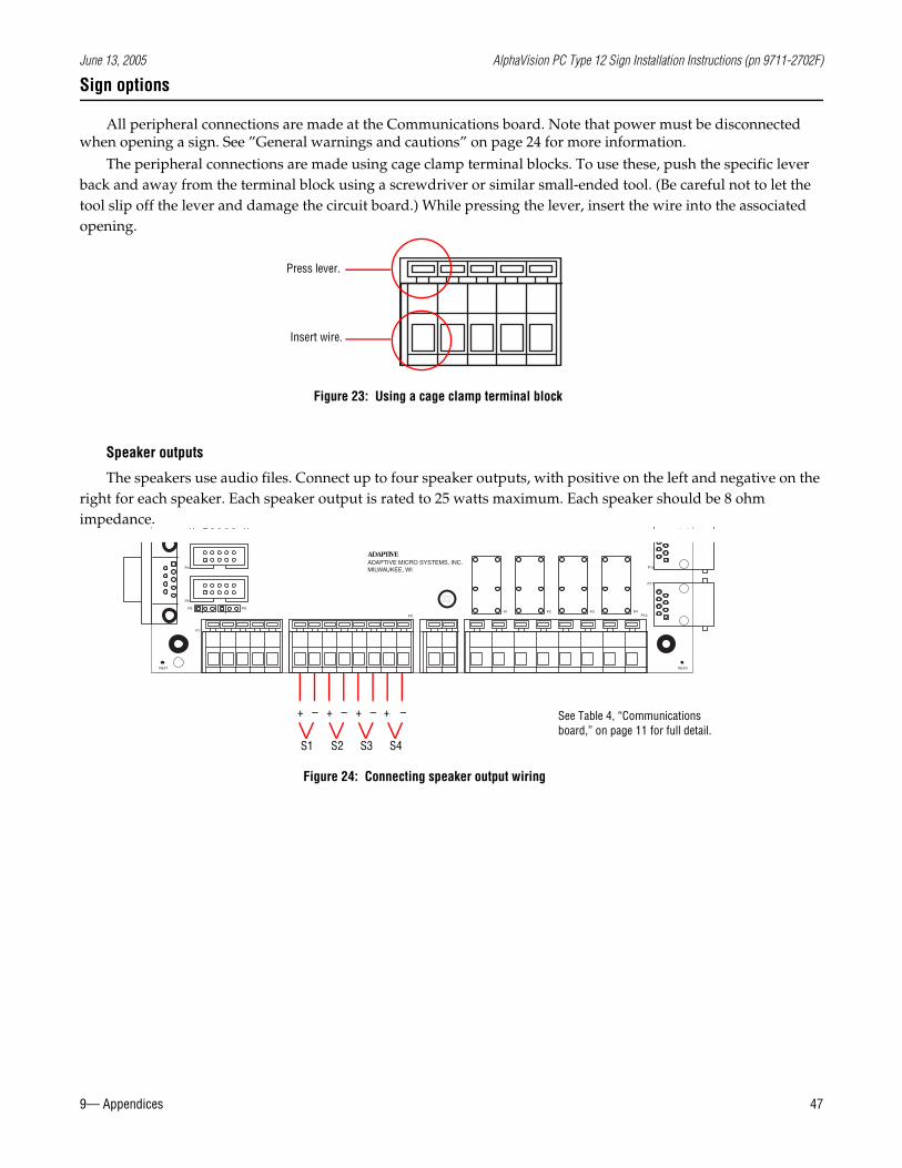
Sign options
All peripheral connections are made at the Communications board. Note that power must be disconnected when opening a sign. See ”General warnings and cautions” on page 24 for more information.
The peripheral connections are made using cage clamp terminal blocks. To use these, push the specific lever back and away from the terminal block using a screwdriver or similar small-ended tool. (Be careful not to let the tool slip off the lever and damage the circuit board.) While pressing the lever, insert the wire into the associated opening.
Speaker outputs
The speakers use audio files. Connect up to four speaker outputs, with positive on the left and negative on the right for each speaker. Each speaker output is rated to 25 watts maximum. Each speaker should be 8 ohm impedance.
Press lever.
Insert wire.
Figure 23: Using a cage clamp terminal block
REF1
P5
P6
P4
P8
P3P1
P9K1 K2
REF3
K3 K4P12
P17
P16ADAPTIVE MICRO SYSTEMS, INC.MILWAUKEE, WI
ADAPTIVE
P7
See Table 4, “Communications board,” on page 11 for full detail.
Figure 24: Connecting speaker output wiring
+ – + – + – + –
S1 S2 S3 S4
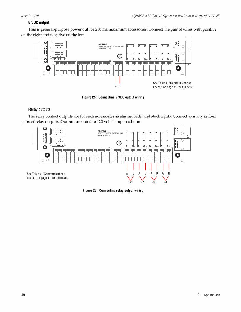
June 13, 2005 AlphaVision PC Type 12 Sign Installation Instructions (pn 9711-2702F)
48 9— Appendices
5 VDC output
This is general-purpose power out for 250 ma maximum accessories. Connect the pair of wires with positive on the right and negative on the left.
Relay outputs
The relay contact outputs are for such accessories as alarms, bells, and stack lights. Connect as many as four pairs of relay outputs. Outputs are rated to 120 volt 4 amp maximum.
REF1
P5
P6
P4
P8
P3P1
P9K1 K2
REF3
K3 K4P12
P17
P16ADAPTIVE MICRO SYSTEMS, INC.MILWAUKEE, WI
ADAPTIVE
P7
See Table 4, “Communications board,” on page 11 for full detail.
Figure 25: Connecting 5 VDC output wiring
– +
REF1
P5
P6
P4
P8
P3P1
P9K1 K2
REF3
K3 K4P12
P17
P16ADAPTIVE MICRO SYSTEMS, INC.MILWAUKEE, WI
ADAPTIVE
P7
See Table 4, “Communications board,” on page 11 for full detail.
Figure 26: Connecting relay output wiring
A B A B A B A B
R1 R2 R3 R4
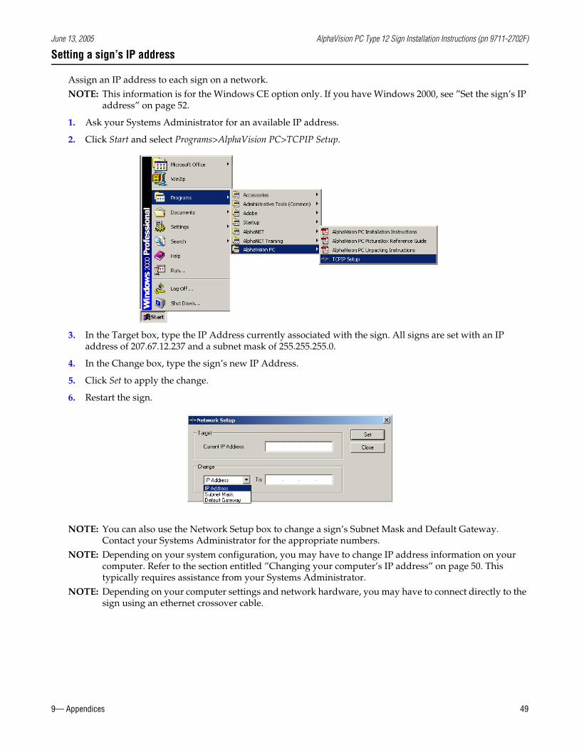
June 13, 2005 AlphaVision PC Type 12 Sign Installation Instructions (pn 9711-2702F)
9— Appendices 49
Setting a sign’s IP address
Assign an IP address to each sign on a network.NOTE: This information is for the Windows CE option only. If you have Windows 2000, see ”Set the sign’s IP
address” on page 52.
1. Ask your Systems Administrator for an available IP address.
2. Click Start and select Programs>AlphaVision PC>TCPIP Setup.
3. In the Target box, type the IP Address currently associated with the sign. All signs are set with an IP address of 207.67.12.237 and a subnet mask of 255.255.255.0.
4. In the Change box, type the sign’s new IP Address.
5. Click Set to apply the change.
6. Restart the sign.
NOTE: You can also use the Network Setup box to change a sign’s Subnet Mask and Default Gateway. Contact your Systems Administrator for the appropriate numbers.
NOTE: Depending on your system configuration, you may have to change IP address information on your computer. Refer to the section entitled ”Changing your computer’s IP address” on page 50. This typically requires assistance from your Systems Administrator.
NOTE: Depending on your computer settings and network hardware, you may have to connect directly to the sign using an ethernet crossover cable.
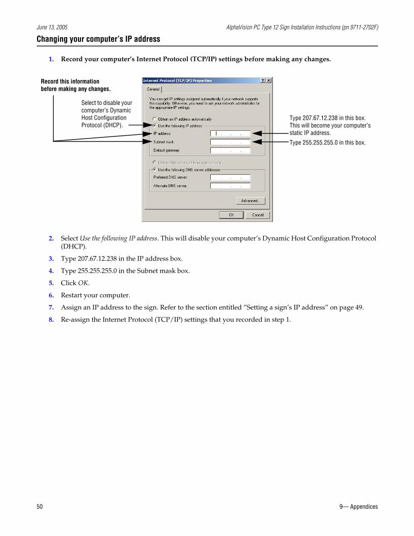
June 13, 2005 AlphaVision PC Type 12 Sign Installation Instructions (pn 9711-2702F)
50 9— Appendices
Changing your computer’s IP address
1. Record your computer’s Internet Protocol (TCP/IP) settings before making any changes.
2. Select Use the following IP address. This will disable your computer’s Dynamic Host Configuration Protocol (DHCP).
3. Type 207.67.12.238 in the IP address box.
4. Type 255.255.255.0 in the Subnet mask box.
5. Click OK.
6. Restart your computer.
7. Assign an IP address to the sign. Refer to the section entitled ”Setting a sign’s IP address” on page 49.
8. Re-assign the Internet Protocol (TCP/IP) settings that you recorded in step 1.
Select to disable your computer’s Dynamic Host Configuration Protocol (DHCP).
Type 207.67.12.238 in this box. This will become your computer’s static IP address.
Record this information before making any changes.
Type 255.255.255.0 in this box.
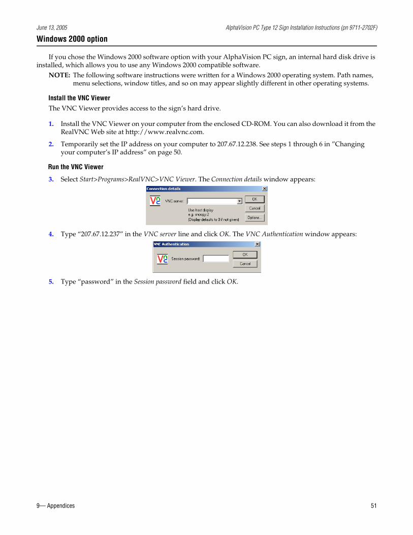
June 13, 2005 AlphaVision PC Type 12 Sign Installation Instructions (pn 9711-2702F)
9— Appendices 51
Windows 2000 option
If you chose the Windows 2000 software option with your AlphaVision PC sign, an internal hard disk drive is installed, which allows you to use any Windows 2000 compatible software.
NOTE: The following software instructions were written for a Windows 2000 operating system. Path names, menu selections, window titles, and so on may appear slightly different in other operating systems.
Install the VNC ViewerThe VNC Viewer provides access to the sign’s hard drive.
1. Install the VNC Viewer on your computer from the enclosed CD-ROM. You can also download it from the RealVNC Web site at http://www.realvnc.com.
2. Temporarily set the IP address on your computer to 207.67.12.238. See steps 1 through 6 in ”Changing your computer’s IP address” on page 50.
Run the VNC Viewer
3. Select Start>Programs>RealVNC>VNC Viewer. The Connection details window appears:
4. Type “207.67.12.237” in the VNC server line and click OK. The VNC Authentication window appears:
5. Type “password” in the Session password field and click OK.
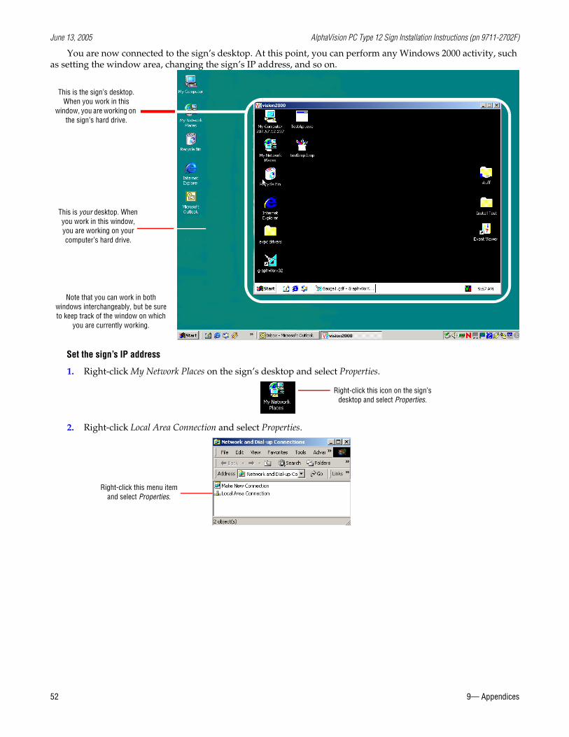
June 13, 2005 AlphaVision PC Type 12 Sign Installation Instructions (pn 9711-2702F)
52 9— Appendices
You are now connected to the sign’s desktop. At this point, you can perform any Windows 2000 activity, such as setting the window area, changing the sign’s IP address, and so on.
Set the sign’s IP address
1. Right-click My Network Places on the sign’s desktop and select Properties.
2. Right-click Local Area Connection and select Properties.
This is the sign’s desktop. When you work in this
window, you are working on the sign’s hard drive.
This is your desktop. When you work in this window, you are working on your computer’s hard drive.
Note that you can work in both windows interchangeably, but be sure to keep track of the window on which
you are currently working.
Right-click this icon on the sign’s desktop and select Properties.
Right-click this menu item and select Properties.
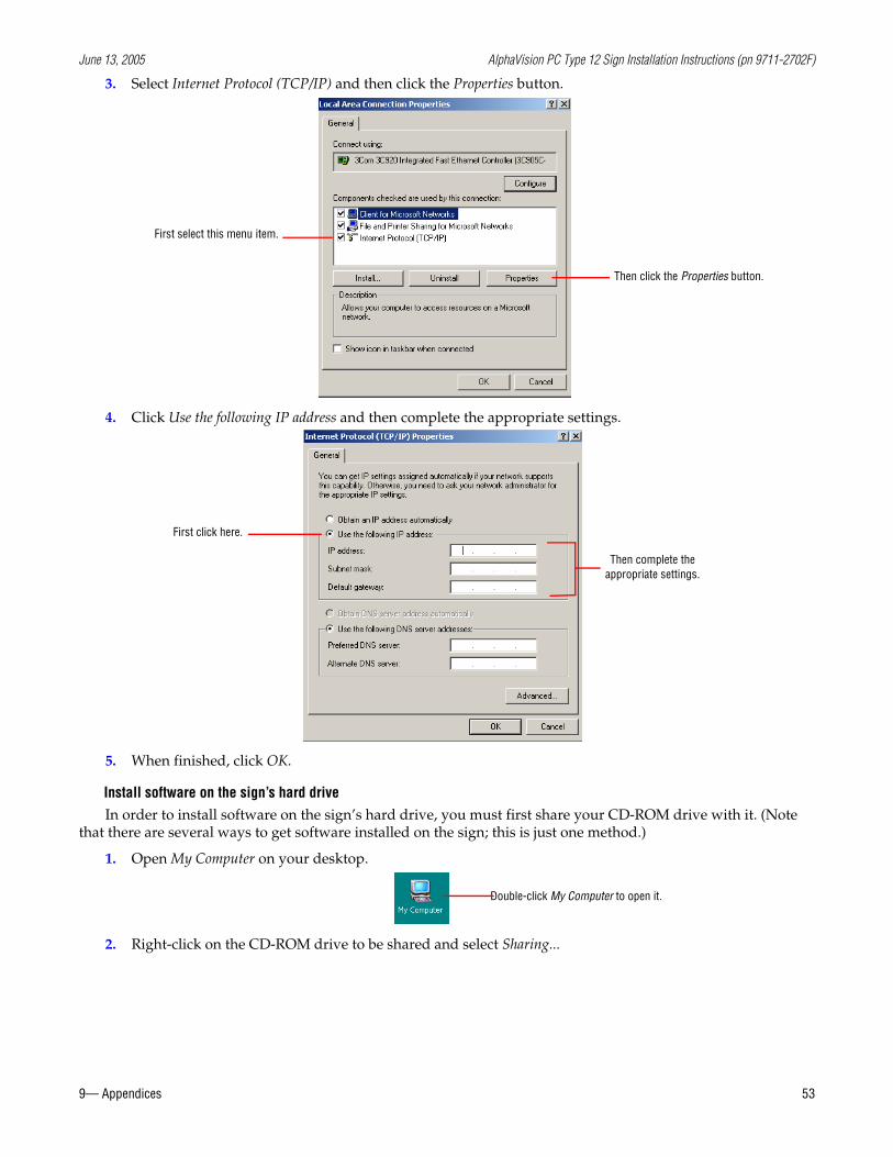
June 13, 2005 AlphaVision PC Type 12 Sign Installation Instructions (pn 9711-2702F)
9— Appendices 53
3. Select Internet Protocol (TCP/IP) and then click the Properties button.
4. Click Use the following IP address and then complete the appropriate settings.
5. When finished, click OK.
Install software on the sign’s hard driveIn order to install software on the sign’s hard drive, you must first share your CD-ROM drive with it. (Note
that there are several ways to get software installed on the sign; this is just one method.)
1. Open My Computer on your desktop.
2. Right-click on the CD-ROM drive to be shared and select Sharing...
Then click the Properties button.
First select this menu item.
First click here.
Then complete the appropriate settings.
Double-click My Computer to open it.
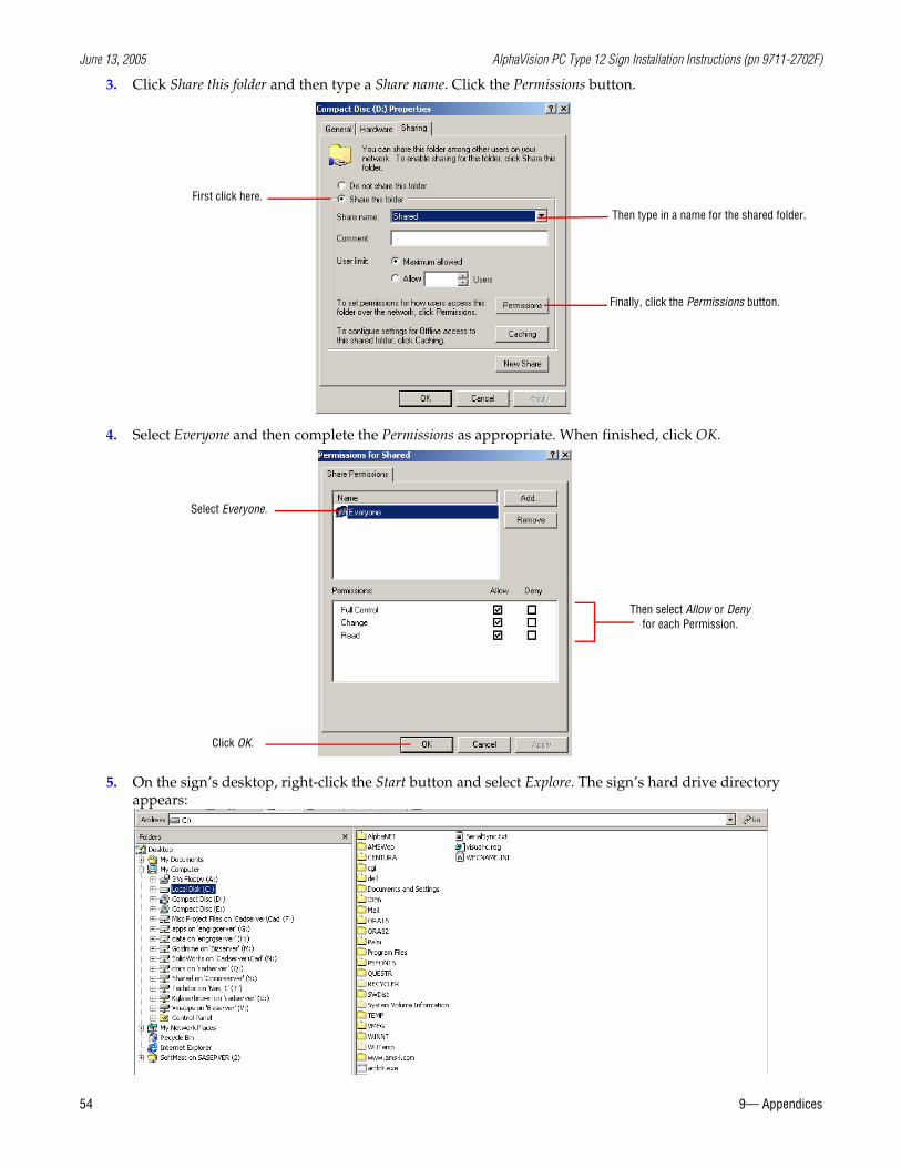
June 13, 2005 AlphaVision PC Type 12 Sign Installation Instructions (pn 9711-2702F)
54 9— Appendices
3. Click Share this folder and then type a Share name. Click the Permissions button.
4. Select Everyone and then complete the Permissions as appropriate. When finished, click OK.
5. On the sign’s desktop, right-click the Start button and select Explore. The sign’s hard drive directory appears:
First click here.
Then type in a name for the shared folder.
Finally, click the Permissions button.
Select Everyone.
Then select Allow or Deny for each Permission.
Click OK.
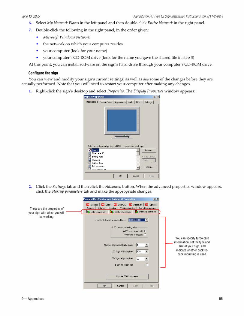
June 13, 2005 AlphaVision PC Type 12 Sign Installation Instructions (pn 9711-2702F)
9— Appendices 55
6. Select My Network Places in the left panel and then double-click Entire Network in the right panel.
7. Double-click the following in the right panel, in the order given:
• Microsoft Windows Network
• the network on which your computer resides
• your computer (look for your name)
• your computer’s CD-ROM drive (look for the name you gave the shared file in step 3)
At this point, you can install software on the sign’s hard drive through your computer’s CD-ROM drive.
Configure the signYou can view and modify your sign’s current settings, as well as see some of the changes before they are
actually performed. Note that you will need to restart your computer after making any changes.
1. Right-click the sign’s desktop and select Properties. The Display Properties window appears:
2. Click the Settings tab and then click the Advanced button. When the advanced properties window appears, click the Startup parameters tab and make the appropriate changes:
These are the properties of your sign with which you will
be working.
You can specify turbo card information, set the type and
size of your sign, and indicate whether back-to-back mounting is used.
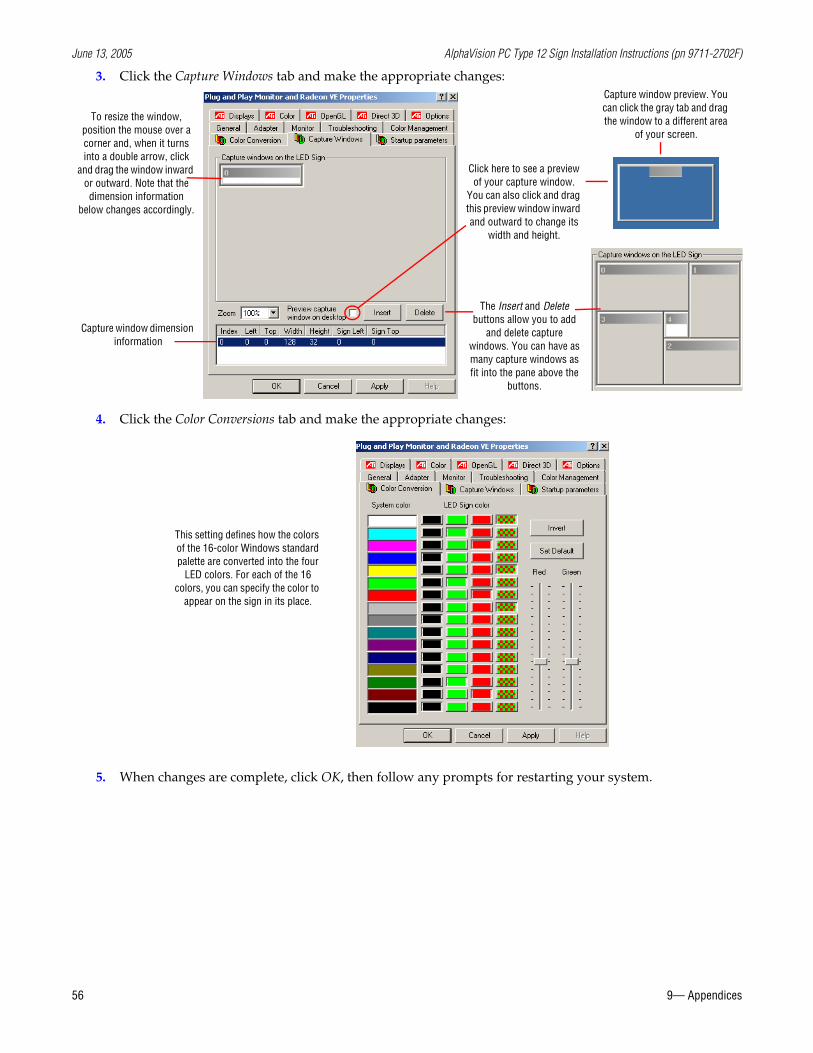
June 13, 2005 AlphaVision PC Type 12 Sign Installation Instructions (pn 9711-2702F)
56 9— Appendices
3. Click the Capture Windows tab and make the appropriate changes:
4. Click the Color Conversions tab and make the appropriate changes:
5. When changes are complete, click OK, then follow any prompts for restarting your system.
To resize the window, position the mouse over a corner and, when it turns into a double arrow, click
and drag the window inward or outward. Note that the dimension information
below changes accordingly.
Click here to see a preview of your capture window.
You can also click and drag this preview window inward and outward to change its
width and height.
Capture window dimension information
Capture window preview. You can click the gray tab and drag the window to a different area
of your screen.
The Insert and Delete buttons allow you to add
and delete capture windows. You can have as many capture windows as fit into the pane above the
buttons.
This setting defines how the colors of the 16-color Windows standard palette are converted into the four
LED colors. For each of the 16 colors, you can specify the color to
appear on the sign in its place.
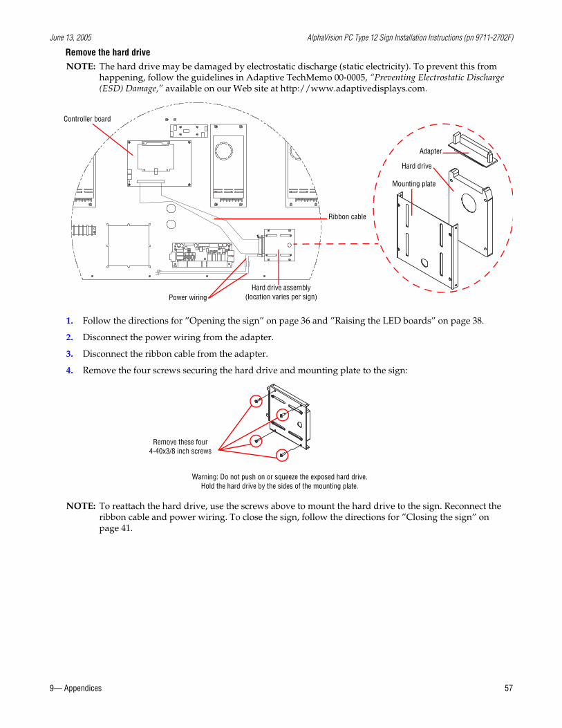
June 13, 2005 AlphaVision PC Type 12 Sign Installation Instructions (pn 9711-2702F)
9— Appendices 57
Remove the hard driveNOTE: The hard drive may be damaged by electrostatic discharge (static electricity). To prevent this from
happening, follow the guidelines in Adaptive TechMemo 00-0005, “Preventing Electrostatic Discharge (ESD) Damage,” available on our Web site at http://www.adaptivedisplays.com.
1. Follow the directions for ”Opening the sign” on page 36 and ”Raising the LED boards” on page 38.
2. Disconnect the power wiring from the adapter.
3. Disconnect the ribbon cable from the adapter.
4. Remove the four screws securing the hard drive and mounting plate to the sign:
NOTE: To reattach the hard drive, use the screws above to mount the hard drive to the sign. Reconnect the ribbon cable and power wiring. To close the sign, follow the directions for ”Closing the sign” on page 41.
Mounting plate
Adapter
Hard drive
Controller board
Ribbon cable
Hard drive assembly (location varies per sign)Power wiring
Remove these four 4-40x3/8 inch screws
Warning: Do not push on or squeeze the exposed hard drive.Hold the hard drive by the sides of the mounting plate.

June 13, 2005 AlphaVision PC Type 12 Sign Installation Instructions (pn 9711-2702F)
58 9— Appendices