Embed Size (px)
Citation preview

MElec-Ch4 - 1
Chapter 4
Alternating CurrentPower
MElec-Ch4 - 2
Overview
• What is Alternating Current• AC Hazards• AC Power Requirements• Shoreside Utility System• On-Board Generators
MElec-Ch4 - 3
What is Alternating Current
• General Description
• Basic Terminology

MElec-Ch4 - 4
General Description
• Batteries provide limited amount of power Can’t run air conditioner or heater DC appliances are expensive
• Therefore need for AC on boat From shore power From on-board generator
• Need “Service Drop” Not an extension cord Safety hazards with AC power
MElec-Ch4 - 5
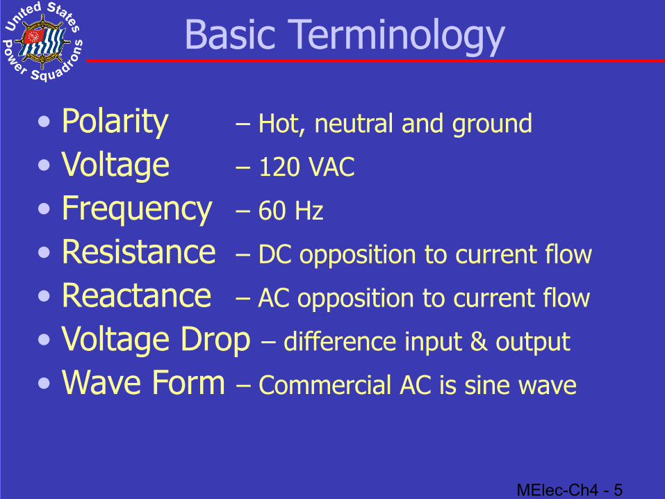
Basic Terminology
• Polarity – Hot, neutral and ground
• Voltage – 120 VAC
• Frequency – 60 Hz
• Resistance – DC opposition to current flow
• Reactance – AC opposition to current flow
• Voltage Drop – difference input & output
• Wave Form – Commercial AC is sine wave
MElec-Ch4 - 6
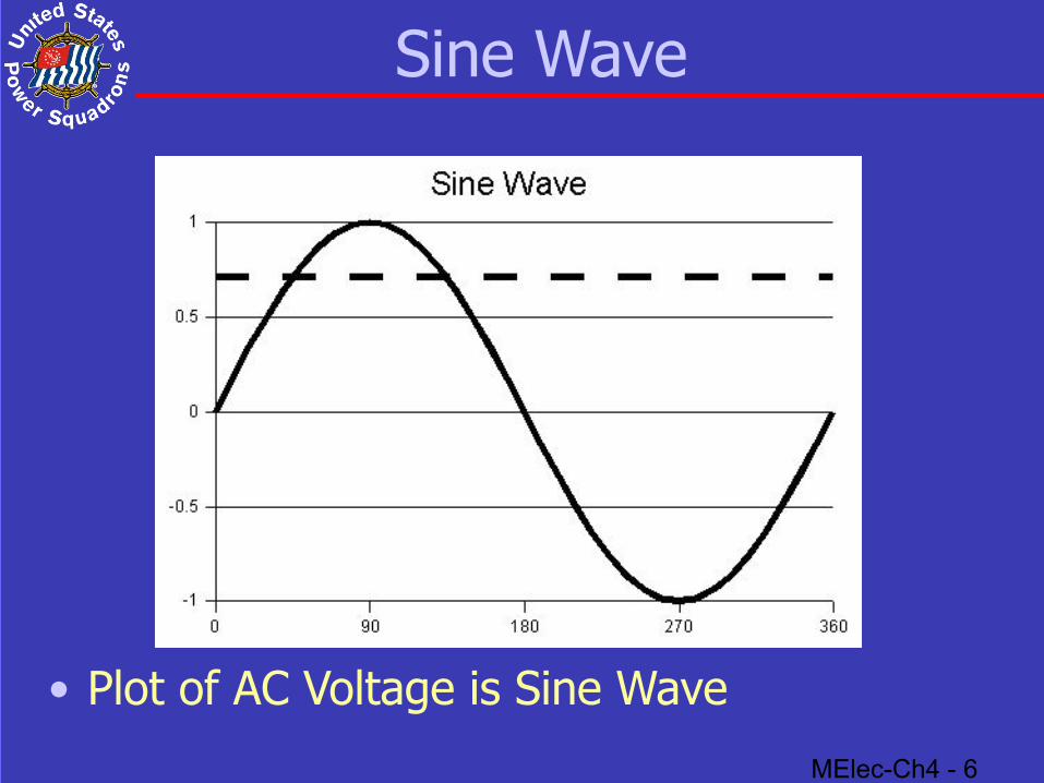
Sine Wave
• Plot of AC Voltage is Sine Wave
MElec-Ch4 - 7
AC Hazards
• Shock
• Fire
• Reversed Polarity
MElec-Ch4 - 8
Shock and Fire
• Shock AC “shock” could be lethal Marine environment increases this hazard Need GFCI protection
• Fire Inadequate wiring and overloaded cables Over fusing or no overload protection Heater on extension cord
MElec-Ch4 - 9
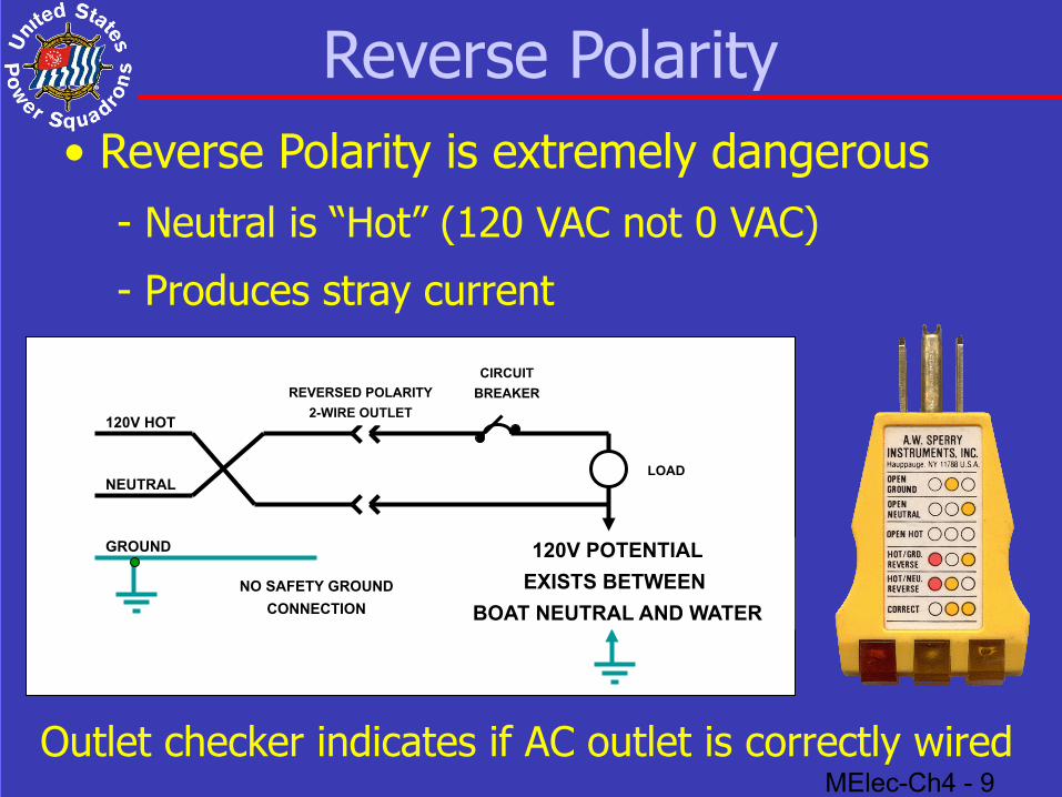
Reverse Polarity
120V HOT
NEUTRAL
CIRCUIT
BREAKER
NO SAFETY GROUND
CONNECTION
REVERSED POLARITY
2-WIRE OUTLET
GROUND
LOAD
120V POTENTIAL
EXISTS BETWEEN
BOAT NEUTRAL AND WATER
• Reverse Polarity is extremely dangerous- Neutral is “Hot” (120 VAC not 0 VAC)
- Produces stray current
Outlet checker indicates if AC outlet is correctly wired
MElec-Ch4 - 10
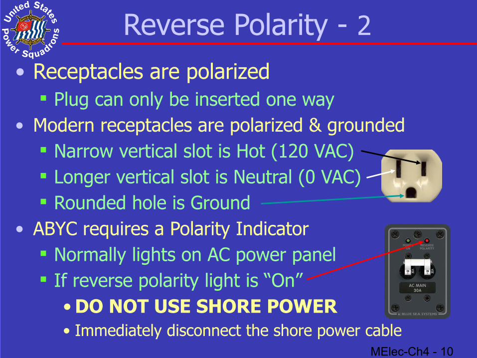
Reverse Polarity - 2• Receptacles are polarized
Plug can only be inserted one way• Modern receptacles are polarized & grounded
Narrow vertical slot is Hot (120 VAC) Longer vertical slot is Neutral (0 VAC) Rounded hole is Ground
• ABYC requires a Polarity Indicator Normally lights on AC power panel If reverse polarity light is “On”
• DO NOT USE SHORE POWER• Immediately disconnect the shore power cable
MElec-Ch4 - 11
AC Power Requirements
• Maximum Current Limitations
• Priority Usage Table

MElec-Ch4 - 12
Maximum Current Limitations
• Dockside Outlet
• Service Cord
• Boat’s Service Entrance

MElec-Ch4 - 13
Dockside Outlet• 30A outlet protected by 30A circuit breaker• 15 A outlet protected by 15A circuit breaker• If 15A to 30A adapter plugged into 15A outlet and
30A cable plugged into adapter Current available limited to 15 Amps
• A 30A to 20A adapter permits a 15A cord to be plugged into dockside outlet NOT SAFE!
• No GFCI protection• Outlet is overprotected

MElec-Ch4 - 14
Service Cord
• 30A, 120 VAC service cord wire is AWG #10• 50A, 120 VAC service cord wire is AWG #6• Service cords are 25 and 50’
Cords are rated for 50’ length
• Limit for #10 wire carrying 30A is 60’ Ch 2 Wire Size Selection Table When two 30A service cords connected together,
safe current is limited to 20 Amps
• Similar problem for two 50A cords
MElec-Ch4 - 15
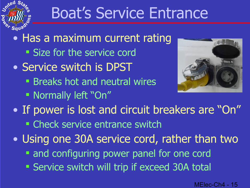
Boat’s Service Entrance
• Has a maximum current rating Size for the service cord
• Service switch is DPST Breaks hot and neutral wires Normally left “On”
• If power is lost and circuit breakers are “On” Check service entrance switch
• Using one 30A service cord, rather than two and configuring power panel for one cord Service switch will trip if exceed 30A total
MElec-Ch4 - 16
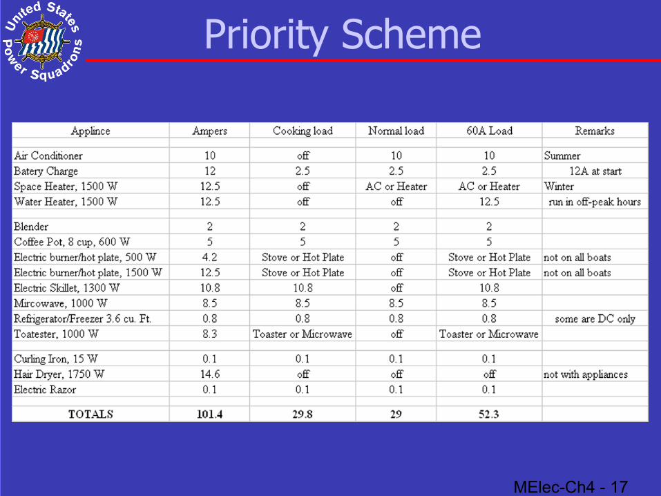
Priority Usage Table
• Maximum current limited by smaller of: Dockside outlet and circuit breaker Service cord Service inlet and service switch (circuit breaker)
• Following table gives typical AC power use Everything cannot be on at same time Prioritize demand based on limiting factor
MElec-Ch4 - 17
Priority Scheme
MElec-Ch4 - 18
Shoreside Utility System
• Utility Power Distribution• Shoreside Outlets• Dockside Service Drop• Shore Power Service Cable• Connector Standards and Adapters• Service Entrance and Distribution
MElec-Ch4 - 19
Utility Power Distribution
• Power lines are at 2,300 VAC or higher
• Output from last transformer is 120/240 V If loads are balanced, no current in neutral Hot wires are Black and Red
• 120 VAC from either wire to neutral• 240 VAC between black and red wires
Center tap of transformer is grounded
• No current flows in ground (green) wire
MElec-Ch4 - 20
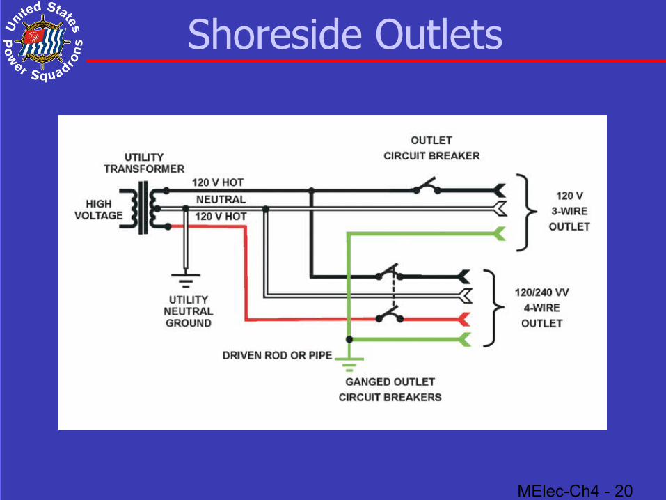
Shoreside Outlets
MElec-Ch4 - 21
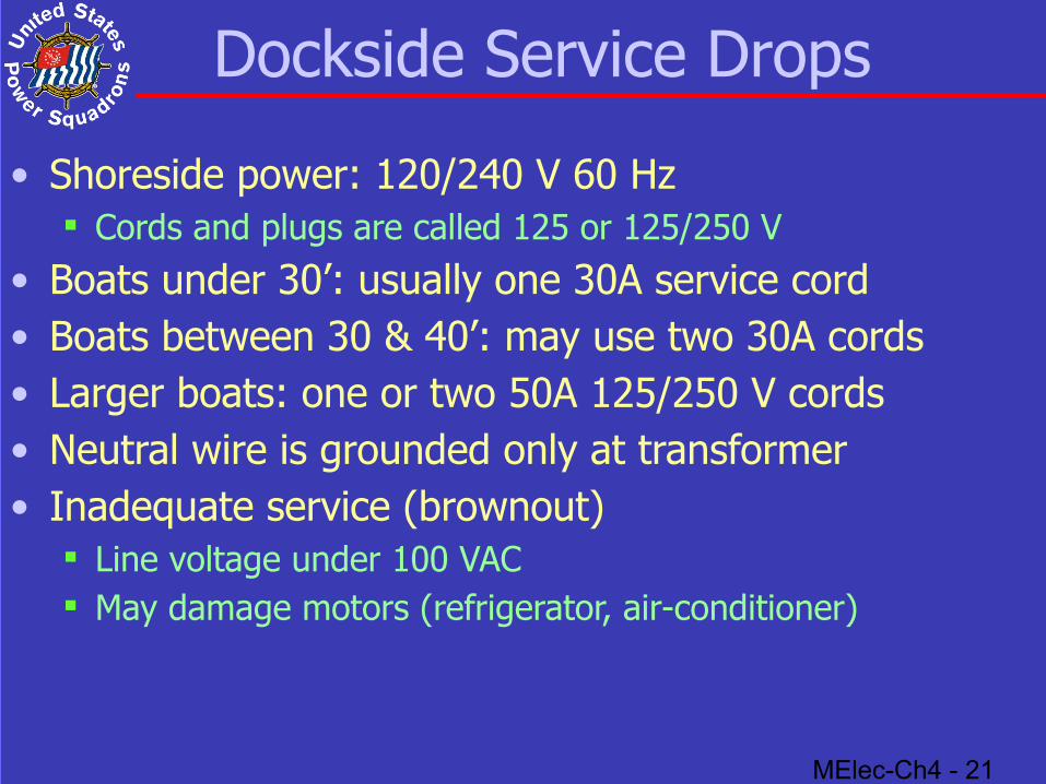
Dockside Service Drops
• Shoreside power: 120/240 V 60 Hz Cords and plugs are called 125 or 125/250 V
• Boats under 30’: usually one 30A service cord• Boats between 30 & 40’: may use two 30A cords• Larger boats: one or two 50A 125/250 V cords• Neutral wire is grounded only at transformer• Inadequate service (brownout)
Line voltage under 100 VAC May damage motors (refrigerator, air-conditioner)
MElec-Ch4 - 22
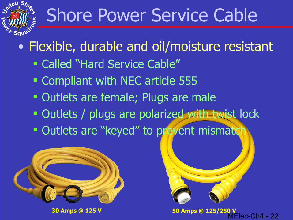
Shore Power Service Cable
• Flexible, durable and oil/moisture resistant Called “Hard Service Cable” Compliant with NEC article 555 Outlets are female; Plugs are male Outlets / plugs are polarized with twist lock Outlets are “keyed” to prevent mismatch
30 Amps @ 125 V 50 Amps @ 125/250 V
MElec-Ch4 - 23
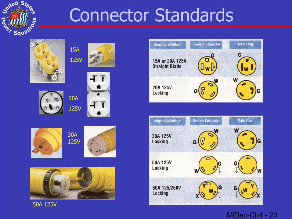
Connector Standards
50A 125V
30A125V
20A
125V
15A
125V
MElec-Ch4 - 24
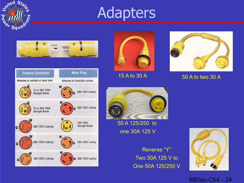
Adapters
Reverse “Y”
Two 30A 125 V to
One 50A 125/250 V
15 A to 30 A 50 A to two 30 A
50 A 125/250 to
one 30A 125 V
MElec-Ch4 - 25
Service Entrance & Distribution
• Service Entrance Connector• Isolation Transformer• Galvanic Isolator• AC Distribution Panel• Branch Circuit Conductors
MElec-Ch4 - 26
Service Entrance Connector• Normally one or two
30A 125 V or 50A 125 V or 50A 125/250 V Most houses have 200A 125/250 V
• Close weatherproof cover when not in use Clean contacts with Electronic Cleaner
• Sequence for Shore Power service cord Turn “Off” all circuit breakers Connect boat end first Then connect shore end Turn “On” shore circuit breaker Check Reverse Polarity for proper connection Turn “On” boat Main then Branch circuits
MElec-Ch4 - 27
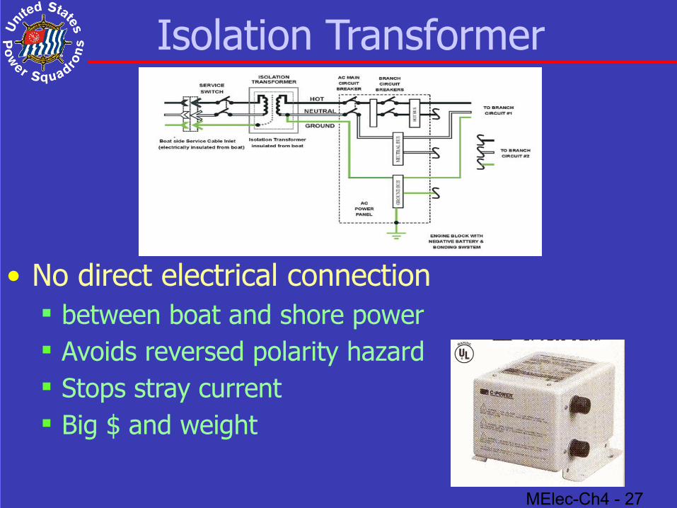
Isolation Transformer
• No direct electrical connection between boat and shore power Avoids reversed polarity hazard Stops stray current Big $ and weight
MElec-Ch4 - 28
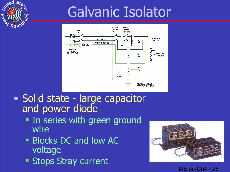
Galvanic Isolator
• Solid state - large capacitor and power diode
In series with green ground wire
Blocks DC and low AC voltage
Stops Stray current
MElec-Ch4 - 29
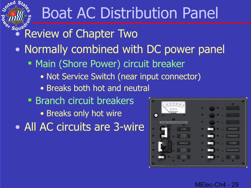
Boat AC Distribution Panel• Review of Chapter Two• Normally combined with DC power panel
Main (Shore Power) circuit breaker• Not Service Switch (near input connector)• Breaks both hot and neutral
Branch circuit breakers• Breaks only hot wire
• All AC circuits are 3-wire
MElec-Ch4 - 30
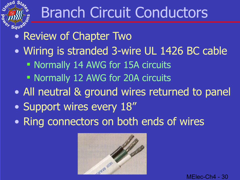
Branch Circuit Conductors• Review of Chapter Two• Wiring is stranded 3-wire UL 1426 BC cable
Normally 14 AWG for 15A circuits Normally 12 AWG for 20A circuits
• All neutral & ground wires returned to panel• Support wires every 18” • Ring connectors on both ends of wires
MElec-Ch4 - 31
On-Board Generators
• Inverters• Propulsion-engine driven generator• Auxiliary-engine driven generator• Isolation from Shore Power Entrance
MElec-Ch4 - 32
Inverters
• Convert DC to AC 12 VDC to 120 V 60 Hz Efficiency 90 to 95%
• Sizes from 50 to 3,000 watts 1200 watts of 120 VAC draws 110A of 12 VDC
• Outputs are 120 V 60 Hz True Sine Wave are expensive
• Run all loads Modified Sine Wave are less expensive
• May damage sensitive electronic equipment
MElec-Ch4 - 33
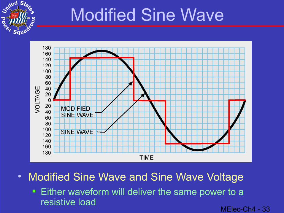
Modified Sine Wave
• Modified Sine Wave and Sine Wave Voltage Either waveform will deliver the same power to a
resistive load
MElec-Ch4 - 34
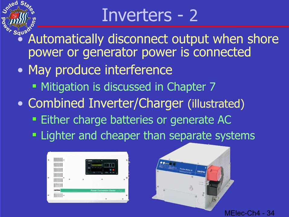
Inverters - 2• Automatically disconnect output when shore
power or generator power is connected• May produce interference
Mitigation is discussed in Chapter 7• Combined Inverter/Charger (illustrated)
Either charge batteries or generate AC Lighter and cheaper than separate systems

MElec-Ch4 - 35
Propulsion-Engine Driven
• AC Generators driven by propulsion engine Can only be used while underway Will not produce full output at idle
• Not as efficient as auxiliary driven generator

MElec-Ch4 - 36
Auxiliary-Engine Driven
• Directly coupled to small gas or diesel engine Fuel should be same as propulsion engine
• Solution if need over 2 Kw of 60 Hz power• Big, heavy and noisy
MElec-Ch4 - 37
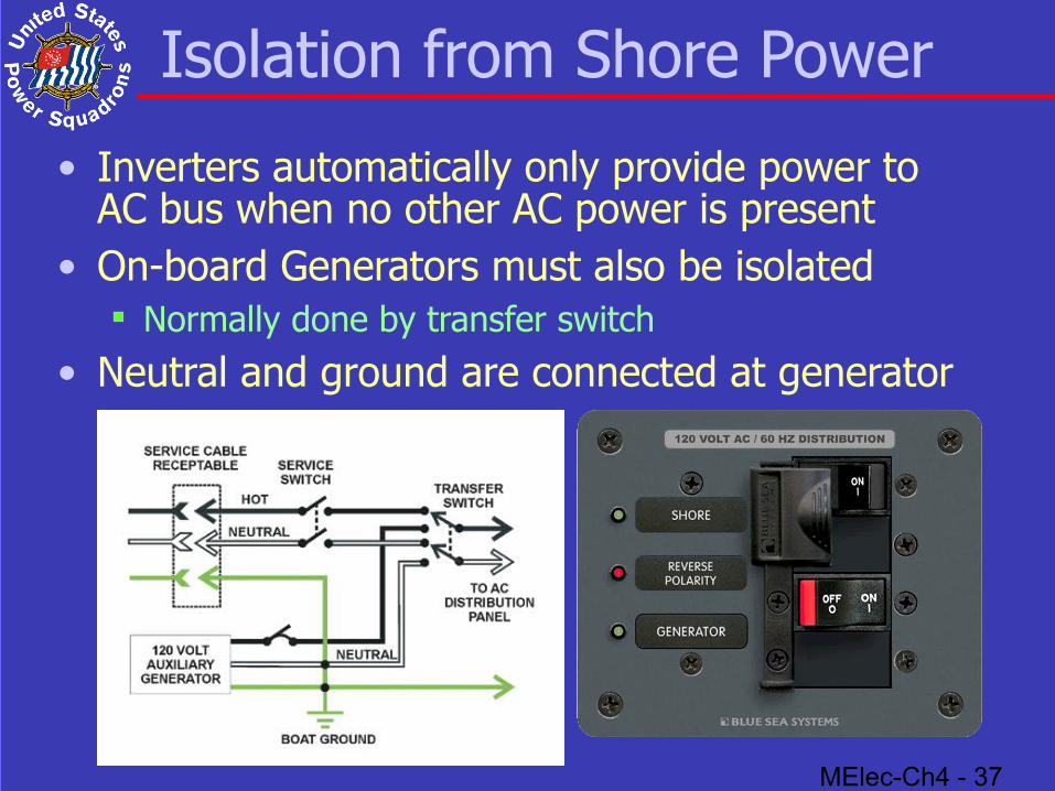
Isolation from Shore Power
• Inverters automatically only provide power to AC bus when no other AC power is present
• On-board Generators must also be isolated Normally done by transfer switch
• Neutral and ground are connected at generator
MElec-Ch4 - 38
Summary
• Polarity reversed: Don’t use shore power
• Nominal shoreside power: 120/240 volts, 60 Hz
• Maximum current limited (smaller of): Dockside circuit breaker, dockside outlet Service cord and boat’s service entrance
• Priority scheme for AC appliances needed
• Outlets must be 3-wire polarized GFCI in galley, head, machinery spaces & weather deck
• Inverters: for short term loads under 2 Kw
• Generators: for long term loads over 2 Kw
• Use transfer switch with inverter or generator