Embed Size (px)
Citation preview
IEEE TRANSACTIONS ON VEHICULAR TECHNOLOGY, VOL. 60, NO. 8, OCTOBER 2011 3625
Alternative Energy Vehicles Drive System:Control, Flux and Torque Estimation,
and Efficiency OptimizationHabib-ur Rehman and Longya Xu, Fellow, IEEE
Abstract—Indirect field-oriented control, direct field-oriented control, and direct torque control are the mostwidely used instantaneous torque control techniques for thedrive system of alternative energy vehicles (AEVs). This paperevaluates three candidate alternating-current machines andinvestigates the suitability of different control techniques for thedrive systems of battery-powered electric vehicles, hybrid electricvehicles, and integrated starter alternators. Accurate flux andtorque estimation is the core of any opted control technique for alltypes of AEV drive systems. Therefore, an accurate closed-loopvoltage model flux and torque estimator that is insensitive tostator resistance variation has been designed. This paper alsoanalyzes loss model control and search control (SC) techniquesfor the drive system’s efficiency optimization and proposes anoffline SC efficiency optimization technique. Experimental resultsare presented to demonstrate the performance of the proposedflux and torque estimator and efficiency optimizer.
Index Terms—Direct torque control (DTC), efficiency optimiza-tion, electric vehicle, field-oriented control (FOC), flux estimation,hybrid electric vehicles (HEVs), starter alternator, torqueestimation.
I. INTRODUCTION
FAST diminishing fossil fuel resources, increasing demandfor conventional personal vehicles, and concerns for envi-
ronmental protection continuously promote interest in the re-search and development of alternative energy vehicles (AEVs)[1]. An electric motor drive is a common propulsion systemfor all kinds of AEVs. The field-oriented control (FOC), whichwas invented in the early 1970s [2], and the direct torquecontrol (DTC), which was invented around the mid-1980s[3], are the two most widely used techniques for almost alltypes of adjustable-speed drives (ASDs), including AEVs. Thecurrent model flux observer is mostly used for indirect field-oriented (IFO) and direct field-oriented (DFO) control, whereasa voltage model flux observer is chosen for DFO and DTCtypes of drive systems. These observers have intensively been
Manuscript received September 7, 2010; revised April 13, 2011 and June 5,2011; accepted June 29, 2011. Date of publication August 4, 2011; date ofcurrent version October 20, 2011. The review of this paper was coordinated byDr. K. Deng.
H. Rehman is with the Department of Electrical Engineering, Collegeof Engineering, American University of Sharjah, Sharjah, U.A.E. (e-mail:[email protected]).
L. Xu is with the Department of Electrical and Computer Engineer-ing, The Ohio State University, Columbus, OH 43210 USA (e-mail:[email protected]).
Color versions of one or more of the figures in this paper are available onlineat http://ieeexplore.ieee.org.
Digital Object Identifier 10.1109/TVT.2011.2163537
examined for accurate and robust flux estimation. Accurate fluxestimation is the core of optimal flux setting and regulation.Only accurate flux estimation can guarantee accurate torqueestimation and, thus, provide torque regulation both for theFOC and DTC drive systems [4]–[22].
The closed-loop current model and voltage model observersare designed for flux estimation and are documented to performbetter, compared with open-loop observers. Flux estimation,when using current model flux observer, does not work well athigh speed due to its sensitivity to rotor resistance [4]. A closed-loop voltage model flux observer is an alternative approach forovercoming the problem of rotor resistance variation. It has,however, been well documented [4]–[11] that flux estimation,when using the voltage model observer, faces the problemsof stator resistance sensitivity and, most of the time, requiresadditional voltage sensors. One suggested alternative [5] isto use the current model observer at low frequency and thevoltage model observer at high frequency, thus benefiting fromtheir advantages and overcoming the limitations of the twoobservers. Although this solution overcomes the problems ofrotor time constant and stator resistance variation, it does notcompletely eliminate the observers’ reliance on the rotor andstator resistances. Stator flux orientation [7], [8] is suggestedto reduce the effect of leakage inductance when using thevoltage model flux observer. Other stator resistance adaptationtechniques are also presented in [9]–[11], but all of thesetechniques overcome the problem of stator resistance variationby providing an estimation of the stator resistance. They neitherprovide the exact value of the stator resistance nor completelyeliminate the observer’s dependence on it. In addition, accuratevoltage signal information is needed most of the time, whichrequires additional voltage sensors.
Currently, sliding-mode observers are intensively investi-gated [12]–[22] for their effectiveness and better performanceto overcome the aforementioned problems. In our earlier work[20], a current model observer for flux and speed estimation wasdesigned. The unique feature of the proposed observer was thatit was completely insensitive to the rotor time constant effect.This paper presents a closed-loop voltage model flux and torqueestimator that does not require the stator resistance information.In addition, voltage measurement is not required, eliminatingthe need for voltage sensors. A detailed discussion on theproposed observer design, including its stability analysis andderivation from the generalized model of induction machinein the stationary frame of reference, has been presented in[21] and [22].
0018-9545/$26.00 © 2011 IEEE
3626 IEEE TRANSACTIONS ON VEHICULAR TECHNOLOGY, VOL. 60, NO. 8, OCTOBER 2011
The FOC and DTC drive systems, which are realized inAEVs and several other industrial applications, provide anindependent control of flux because of the natural decouplingof the flux- and torque-producing currents. This independentcontrol of flux is utilized to maximize the machine efficiencyat various operating conditions. The loss model control (LMC)and search control (SC) methods [23]–[31] are two of themost widely used techniques for the optimal flux setting ofa vector-controlled drive system. As the name implies, LMCneeds a system model for finding the optimal flux setting atany operating condition [23]–[27]. Therefore, this techniqueis dependent on the accurate motor parameters information.The basic principle of the SC method is to iteratively searchonline for the flux settings, which require a minimum in-put power for a given torque and speed [26]–[31]. The SCmethod suffers from the disadvantages of slow convergenceand torque ripples. This paper proposes a simple yet verypractical offline SC approach for the flux control to operatethe machine at optimal efficiency. The machine is operatedon the dynamometer in the speed control mode, and a direct-current (dc) power generation command for battery chargingis set. The instrumentation is based on a setup that measuresthe input mechanical power of the machine and the outputelectrical power at the dc bus. The rotor flux (and, hence,the flux current ids) is iterated for minimum input mechanicalpower on the motor shaft for generating the desired output dcpower. These offline optimal flux current data are collected andused in a table lookup, which is implemented in the machinecontroller for various operating conditions. The advantages ofthe proposed offline SC technique, compared with the onlineSC method, are listed as follows: 1) It does not suffer fromthe slow convergence problem; 2) it has fewer torque ripples,because it does not keep changing the flux level while searchingfor the optimal value; and 3) it is more accurate, becausethe input and output power is measured offline using voltage,current, torque, and speed transducers, making it insensitiveto any error that could occur in the online SC technique dueto input or output power estimation. However, the disadvan-tage of the proposed method is that it does not account forall the operating conditions and the machine has to inten-sively be characterized in the laboratory before putting it intooperation.
This paper is organized as follows. Section II comparesvarious candidate machines for AEV drive systems. It presentsthe basic structure of IFO, DFO, and DTC techniques and in-vestigates the suitability of these control techniques for battery-powered electric vehicle (BEV), hybrid electric vehicle (HEV),and integrated starter alternator (ISA) applications. Section IIIpresents the proposed flux and torque estimator and validatesits performance through simulation and experimental study.Finally, Section IV elaborates the proposed offline SC strategyfor the efficiency optimization, whereas the concluding remarksare made in Section V. The work presented in this paper couldmake a meaningful contribution to induction motor drives,because the stator flux and torque observers and the efficiencyoptimizer are equally useful while realizing both the FOCand DTC drive systems used for all types of drive systems,including AEV applications.
II. ALTERNATIVE ENERGY VEHICLE DRIVE
SYSTEM AND CONTROL
The dc machines are no longer a viable option for AEV ap-plications because of their low efficiency, low power-to-weightratio, high maintenance, and high-speed operation limitation.The ac machines are a better alternative for the BEV, HEV, andISA vehicular drive systems. The induction motor, the switchedreluctance motor, and the permanent magnet motor are the threecandidate machines that are examined for these applications.Although the switched reluctance motor has a simpler statorwinding and rugged rotor structure, it has problems of torqueripple, noise, and vibrations. The permanent-magnet synchro-nous (PMS) motor, on the other hand, has higher efficiency butis relatively more expensive, and its magnets are sensitive tohigh temperature. Nevertheless, advancement in the permanenttechnology and ongoing reduction in the permanent magnet’scost keep the future of PMS machines quite promising. Theinduction motor, on the other hand, is well accepted for its widespeed range, complete deenergization, ruggedness, and lowcost.
The 42-V ISA system has been accepted as the new standardpower net by the automotive industry. Based on the author’sexperience [32], for an ISA application, a PMS motor has abetter future compared with the ac induction motor because ofits higher efficiency, particularly when the ISA is powered bya smaller sized battery, compared with a BEV. An ac inductionmotor seems to be a better or comparable choice for BEV andHEV applications because of the aforementioned associatedadvantages. Interestingly, another deciding factor is the expe-rience and technology that major automotive companies havedeveloped. Ford and General Motors are more inclined towardthe induction machine, whereas Toyota and Honda choose thePMS machine for almost all kinds of AEV applications.
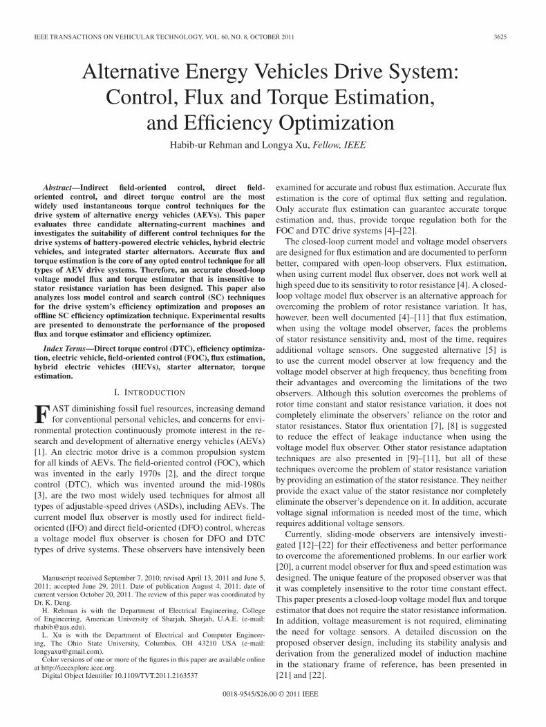
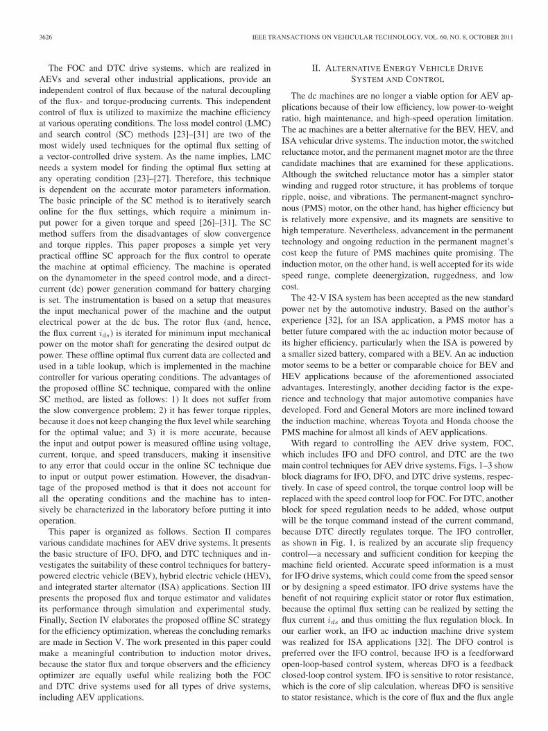
With regard to controlling the AEV drive system, FOC,which includes IFO and DFO control, and DTC are the twomain control techniques for AEV drive systems. Figs. 1–3 showblock diagrams for IFO, DFO, and DTC drive systems, respec-tively. In case of speed control, the torque control loop will bereplaced with the speed control loop for FOC. For DTC, anotherblock for speed regulation needs to be added, whose outputwill be the torque command instead of the current command,because DTC directly regulates torque. The IFO controller,as shown in Fig. 1, is realized by an accurate slip frequencycontrol—a necessary and sufficient condition for keeping themachine field oriented. Accurate speed information is a mustfor IFO drive systems, which could come from the speed sensoror by designing a speed estimator. IFO drive systems have thebenefit of not requiring explicit stator or rotor flux estimation,because the optimal flux setting can be realized by setting theflux current ids and thus omitting the flux regulation block. Inour earlier work, an IFO ac induction machine drive systemwas realized for ISA applications [32]. The DFO control ispreferred over the IFO control, because IFO is a feedforwardopen-loop-based control system, whereas DFO is a feedbackclosed-loop control system. IFO is sensitive to rotor resistance,which is the core of slip calculation, whereas DFO is sensitiveto stator resistance, which is the core of flux and the flux angle
REHMAN AND XU: AEV SYSTEM: CONTROL, FLUX AND TORQUE ESTIMATION, AND EFFICIENCY OPTIMIZATION 3627
Fig. 1. IFO drive system.
Fig. 2. DFO drive system.
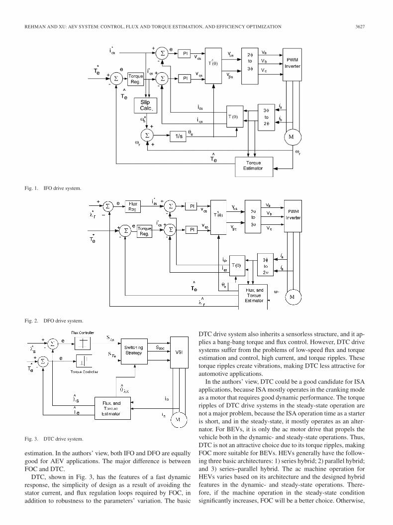
Fig. 3. DTC drive system.
estimation. In the authors’ view, both IFO and DFO are equallygood for AEV applications. The major difference is betweenFOC and DTC.
DTC, shown in Fig. 3, has the features of a fast dynamicresponse, the simplicity of design as a result of avoiding thestator current, and flux regulation loops required by FOC, inaddition to robustness to the parameters’ variation. The basic
DTC drive system also inherits a sensorless structure, and it ap-plies a bang-bang torque and flux control. However, DTC drivesystems suffer from the problems of low-speed flux and torqueestimation and control, high current, and torque ripples. Thesetorque ripples create vibrations, making DTC less attractive forautomotive applications.
In the authors’ view, DTC could be a good candidate for ISAapplications, because ISA mostly operates in the cranking modeas a motor that requires good dynamic performance. The torqueripples of DTC drive systems in the steady-state operation arenot a major problem, because the ISA operation time as a starteris short, and in the steady-state, it mostly operates as an alter-nator. For BEVs, it is only the ac motor drive that propels thevehicle both in the dynamic- and steady-state operations. Thus,DTC is not an attractive choice due to its torque ripples, makingFOC more suitable for BEVs. HEVs generally have the follow-ing three basic architectures: 1) series hybrid; 2) parallel hybrid;and 3) series–parallel hybrid. The ac machine operation forHEVs varies based on its architecture and the designed hybridfeatures in the dynamic- and steady-state operations. There-fore, if the machine operation in the steady-state conditionsignificantly increases, FOC will be a better choice. Otherwise,
3628 IEEE TRANSACTIONS ON VEHICULAR TECHNOLOGY, VOL. 60, NO. 8, OCTOBER 2011
DTC could be selected, but this approach would essentiallymean more of an ISA-type of operation.
III. FLUX AND TORQUE ESTIMATION
An accurate flux and torque estimation is the core of bothDFO- and DTC-types of drive systems. DFO and DTC mayor may not require the motor speed information, depending onthe type of flux observer incorporated. Mostly, for DFO andDTC drive systems, a voltage model flux observer is used,but for a DFO drive system, sometimes, a current model fluxobserver is also used. An open-loop voltage model flux observerdoes not require the machine speed information, whereas for anopen-loop current model observer, the speed signal informationis needed. This condition makes torque-controlled DTC andDFO drive systems inherently sensorless when using the open-loop voltage model flux observer. However, both the currentand voltage model open-loop observers are sensitive to offsetand drift problems and are, with no feedback, necessary forconvergence. Therefore, for both DFO and DTC drive systems,closed-loop observers are preferred over open-loop observers.In this paper, a closed-loop voltage model flux observer that iswell suited for both DFO and DTC drive systems is designed,developed, and implemented.
The proposed closed-loop flux observer is designed basedon the estimated and measured stator currents. The currentestimation error is defined as the difference between the currentthat is measured through the current sensor and the current thatis estimated through the machine model. The equations for theproposed current and flux estimator [21] in the stationary frameof reference are formulated as follows:
piαs =1
σLs(∆αs) − Rr
σLriαs − ωriβs
+Rr
σLsLrλαs +
ωr
σLsλβs
piβs =1
σLs(∆βs) + ωriαs − Rr
σLriβs
− ωr
σLsλαs +
Rr
σLsLrλβs (1)
pλαs = vαs − Rsiαs = ∆αs
pλβs = vβs − Rsiβs = ∆βs (2)
where
σ = 1 − L2m
LsLr(3)
∆αβs = −u0sign(Sαβs) (4)
sign(Sαβ) =
+1, if Sαβ > 1Sαβ , if |Sαβ | ≤ 1−1, if Sαβ < −1
(5)
Sαβs = iαβs − iαβs. (6)
With this choice of sliding-mode functions, the sliding surfaceis given by
Sn = [Sαs Sβs]T . (7)
In this paper, subscripts α and β are used for the stationaryframe of reference, whereas notations d and q represent thesynchronous frame of reference. Equations (1) and (2) arethe current and flux estimator equations, respectively, whichinclude a sliding-mode function ∆αβs, as described by (4)–(6).The sliding-mode function, which is designed around the statorflux terms in the current estimation equation, will drive the esti-mated current to the measured current. When the sliding-modefunction drives the estimated current to the measured current,the function itself gives the estimate of the stator flux, as givenby (2). However, ∆αs and ∆βs will take the extreme values ofu0 and −u0 at a high frequency and will oscillate around theiractual values. To define the control action, which maintains themotion on the sliding manifold, an equivalent-control concept[12] is used. Solving S•
n = 0 for ∆αs and ∆βs will yield theequivalent-control action. In practice, the discontinuous controlcan be considered a combination of an equivalent-control termand a high-frequency switching term. Therefore, the equivalent-control term can be found by isolating the continuous termusing a low-pass filter, which is implemented as
∆eqαβs =
1µs + 1
∆αβs (8)
where µ is the time constant of the filter. It should sufficientlybe small to preserve the slow component undistorted but largeenough to eliminate the high-frequency components. When thetrajectories of the system reach the sliding surface Sn = 0, theobserved currents iαs, iβs match the actual currents iαs, iβs.Then, using (2) and (8), we obtain
∆eqαs = vαs − Rsiαs
∆eqβs = vβs − Rsiβs. (9)
Thus, the stator flux can be estimated based on (2) and (9) as
pλαs = ∆eqαs
pλβs = ∆eqβs. (10)
The estimated stator flux can be used to estimate the rotor fluxand flux angle as follows:
λαr =Lr
Lm(λαs − σLsiαs)
λβr =Lr
Lm(λβs − σLsiβs) (11)
θe = tan−1 λβr
λαr
. (12)
The proposed approach thus requires the current sensorsand speed sensor or observer in the drive system, becausethe currents estimation equation (1) needs the motor speedinformation. In the real implementation of any induction motordrive system, two current sensors are always in place to measure
REHMAN AND XU: AEV SYSTEM: CONTROL, FLUX AND TORQUE ESTIMATION, AND EFFICIENCY OPTIMIZATION 3629
TABLE ISPECIFICATIONS OF THE LABORATORY PROTOTYPE INDUCTION MOTOR
the current for the current regulation in the case of FOC and forflux estimation and motor protection for both FOC and DTC.DTC is inherently sensorless, but for an internal combustionengine (ICE), a speed sensor is always in place for measuringthe engine speed, which makes the proposed observer equallyuseful for both HEV and ISA applications. With regard to thepure BEV, a sensor can be added on the machine shaft, orbecause the sensorless technology is well developed, a speedestimator can be designed to avoid an encoder on the machineshaft. The measured current and estimated flux in the stationaryframe of reference are used to calculate the torque in a station-ary frame of reference as
Teαβ =3NP
2Lm
Lr(λαriβs − λβriαs). (13)
The torque in a synchronous frame of reference can becalculated by converting the measured current and estimatedflux from a stationary to a synchronous frame of reference as
Te =3NP
2Lm
Lr(λdriqs − λqrids). (14)
Equation (14) indicates that a given torque level can be achievedby adjusting the current iqs, whereas the flux setting is a degreeof freedom and can be set at different values to obtain the samelevel of torque. This degree of freedom is used to optimize themachine efficiency. The proposed algorithm is validated on aprototype 3.75-kW induction machine through the simulationand experimental study. The parameters of the machine aregiven in Table I.
A. Simulation Results
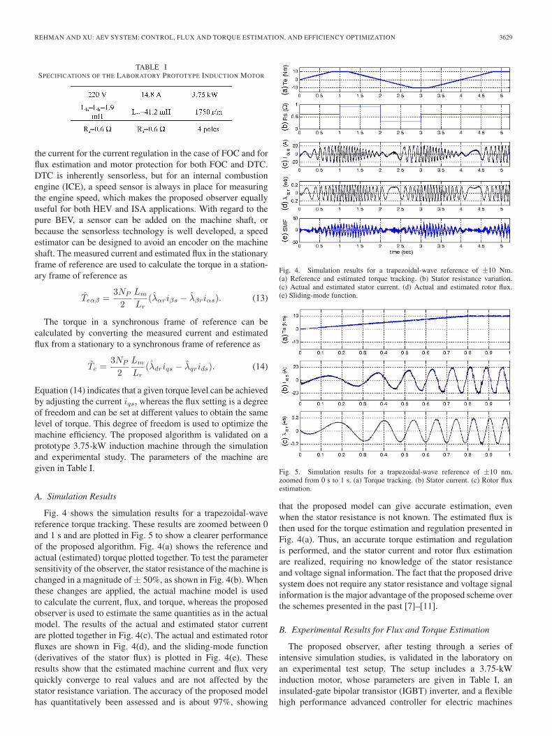
Fig. 4 shows the simulation results for a trapezoidal-wavereference torque tracking. These results are zoomed between 0and 1 s and are plotted in Fig. 5 to show a clearer performanceof the proposed algorithm. Fig. 4(a) shows the reference andactual (estimated) torque plotted together. To test the parametersensitivity of the observer, the stator resistance of the machine ischanged in a magnitude of ± 50%, as shown in Fig. 4(b). Whenthese changes are applied, the actual machine model is usedto calculate the current, flux, and torque, whereas the proposedobserver is used to estimate the same quantities as in the actualmodel. The results of the actual and estimated stator currentare plotted together in Fig. 4(c). The actual and estimated rotorfluxes are shown in Fig. 4(d), and the sliding-mode function(derivatives of the stator flux) is plotted in Fig. 4(e). Theseresults show that the estimated machine current and flux veryquickly converge to real values and are not affected by thestator resistance variation. The accuracy of the proposed modelhas quantitatively been assessed and is about 97%, showing
Fig. 4. Simulation results for a trapezoidal-wave reference of ±10 Nm.(a) Reference and estimated torque tracking. (b) Stator resistance variation.(c) Actual and estimated stator current. (d) Actual and estimated rotor flux.(e) Sliding-mode function.
Fig. 5. Simulation results for a trapezoidal-wave reference of ±10 nm,zoomed from 0 s to 1 s. (a) Torque tracking. (b) Stator current. (c) Rotor fluxestimation.
that the proposed model can give accurate estimation, evenwhen the stator resistance is not known. The estimated flux isthen used for the torque estimation and regulation presented inFig. 4(a). Thus, an accurate torque estimation and regulationis performed, and the stator current and rotor flux estimationare realized, requiring no knowledge of the stator resistanceand voltage signal information. The fact that the proposed drivesystem does not require any stator resistance and voltage signalinformation is the major advantage of the proposed scheme overthe schemes presented in the past [7]–[11].
B. Experimental Results for Flux and Torque Estimation
The proposed observer, after testing through a series ofintensive simulation studies, is validated in the laboratory onan experimental test setup. The setup includes a 3.75-kWinduction motor, whose parameters are given in Table I, aninsulated-gate bipolar transistor (IGBT) inverter, and a flexiblehigh performance advanced controller for electric machines
3630 IEEE TRANSACTIONS ON VEHICULAR TECHNOLOGY, VOL. 60, NO. 8, OCTOBER 2011
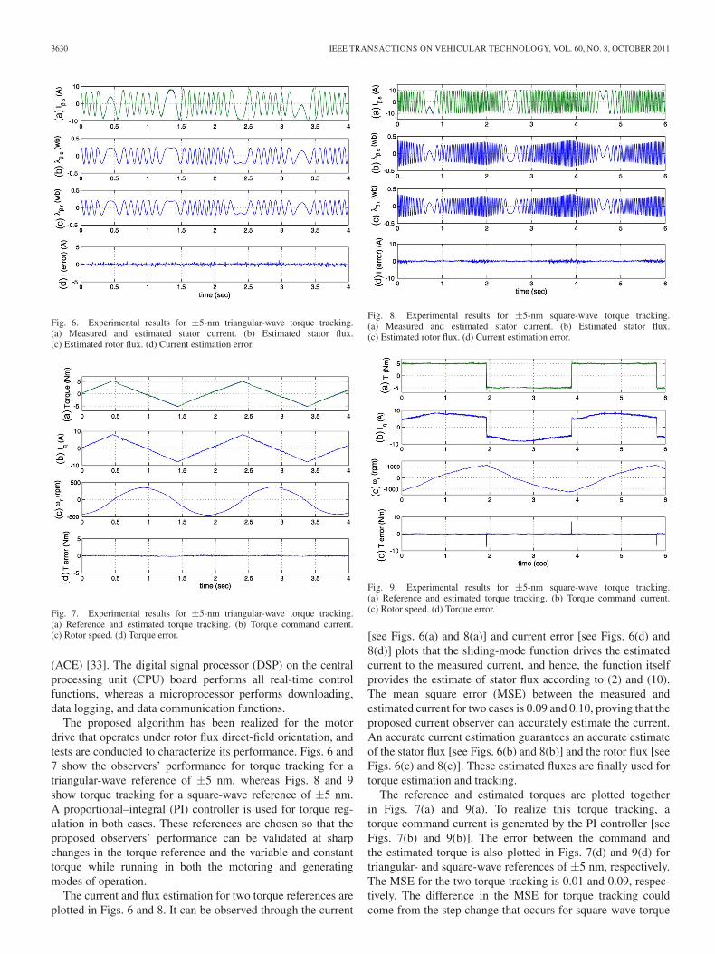
Fig. 6. Experimental results for ±5-nm triangular-wave torque tracking.(a) Measured and estimated stator current. (b) Estimated stator flux.(c) Estimated rotor flux. (d) Current estimation error.
Fig. 7. Experimental results for ±5-nm triangular-wave torque tracking.(a) Reference and estimated torque tracking. (b) Torque command current.(c) Rotor speed. (d) Torque error.
(ACE) [33]. The digital signal processor (DSP) on the centralprocessing unit (CPU) board performs all real-time controlfunctions, whereas a microprocessor performs downloading,data logging, and data communication functions.
The proposed algorithm has been realized for the motordrive that operates under rotor flux direct-field orientation, andtests are conducted to characterize its performance. Figs. 6 and7 show the observers’ performance for torque tracking for atriangular-wave reference of ±5 nm, whereas Figs. 8 and 9show torque tracking for a square-wave reference of ±5 nm.A proportional–integral (PI) controller is used for torque reg-ulation in both cases. These references are chosen so that theproposed observers’ performance can be validated at sharpchanges in the torque reference and the variable and constanttorque while running in both the motoring and generatingmodes of operation.
The current and flux estimation for two torque references areplotted in Figs. 6 and 8. It can be observed through the current
Fig. 8. Experimental results for ±5-nm square-wave torque tracking.(a) Measured and estimated stator current. (b) Estimated stator flux.(c) Estimated rotor flux. (d) Current estimation error.
Fig. 9. Experimental results for ±5-nm square-wave torque tracking.(a) Reference and estimated torque tracking. (b) Torque command current.(c) Rotor speed. (d) Torque error.
[see Figs. 6(a) and 8(a)] and current error [see Figs. 6(d) and8(d)] plots that the sliding-mode function drives the estimatedcurrent to the measured current, and hence, the function itselfprovides the estimate of stator flux according to (2) and (10).The mean square error (MSE) between the measured andestimated current for two cases is 0.09 and 0.10, proving that theproposed current observer can accurately estimate the current.An accurate current estimation guarantees an accurate estimateof the stator flux [see Figs. 6(b) and 8(b)] and the rotor flux [seeFigs. 6(c) and 8(c)]. These estimated fluxes are finally used fortorque estimation and tracking.
The reference and estimated torques are plotted togetherin Figs. 7(a) and 9(a). To realize this torque tracking, atorque command current is generated by the PI controller [seeFigs. 7(b) and 9(b)]. The error between the command andthe estimated torque is also plotted in Figs. 7(d) and 9(d) fortriangular- and square-wave references of ±5 nm, respectively.The MSE for the two torque tracking is 0.01 and 0.09, respec-tively. The difference in the MSE for torque tracking couldcome from the step change that occurs for square-wave torque
REHMAN AND XU: AEV SYSTEM: CONTROL, FLUX AND TORQUE ESTIMATION, AND EFFICIENCY OPTIMIZATION 3631
TABLE IISPECIFICATIONS OF THE INDUCTION MOTOR
Fig. 10. Torque speed characteristics of the HEV/ISA machine.
tracking, or it could be due to the tuning of the PI controller’sgains. However, the MSE for the current estimation for the twocases is about the same, validating the observer performance.The speed signal is also included for completeness and readers’information [see Figs. 7(c) and 9(c)]. The proposed observerproved to effectively regulate the torque while estimating thestator and rotor fluxes of the machine.
IV. MOTOR DESIGN CONSIDERATIONS
AND EFFICIENCY OPTIMIZATION
This paper takes the HEV/ISA drive system as a case studyto demonstrate the proposed offline SC technique for efficiencyoptimization. The motor design for HEV/ISA is relatively dif-ferent, compared with other variable-speed drive applications.Therefore, first, the HEV/ISA motor design considerations arediscussed, and then, the efficiency optimization is presented inthis section.
A. Motor Design Considerations
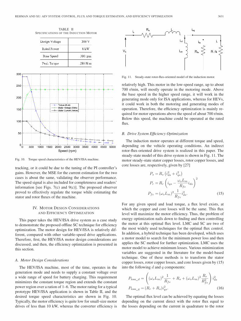
The HEV/ISA machine, most of the time, operates in thegeneration mode and needs to supply a constant voltage overa wide range of speed for battery charging. This requirementminimizes the constant torque region and extends the constantpower region over a ration of 1–6. The motor rating for a typicalprototype HEV/ISA application is shown in Table II, and thedesired torque speed characteristics are shown in Fig. 10.Typically, the motor efficiency is quite low for small-size motordrives of less than 10 kW, whereas the converter efficiency is
Fig. 11. Steady-state rotor-flux-oriented model of the induction motor.
relatively high. This motor in the low-speed range, up to about700 r/min, will mostly operate in the motoring mode. Abovethe base speed in the higher speed range, it will work in thegenerating mode only for ISA applications, whereas for HEVs,it could work in both the motoring and generating modes ofoperation. Therefore, the efficiency optimization is mainly re-quired for motor operations above the speed of about 700 r/min.Below this speed, the machine could be operated at the ratedflux.
B. Drive System Efficiency Optimization
The induction motor operates at different torque and speed,depending on the vehicle operating conditions. An indirectrotor-flux-oriented drive system is realized in this paper. Thesteady-state model of this drive system is shown in Fig. 11. Themotor steady-state stator copper losses, rotor copper losses, andcore losses are, respectively, given by [27]
Ps =Rs
(i2ds + i2qs
)Pr =Rr
(iqs − ωsLm
Rfeids
)2
Pfe = (ωsLm)21
Rfei2ds. (15)
For any given speed and load torque, a flux level exists, atwhich the copper and core losses will be the same. This fluxlevel will maximize the motor efficiency. Thus, the problem ofenergy optimization nails down to finding and then controllingthe motor at this optimal flux level. LMC and SC are two ofthe most widely used techniques for the optimal flux control.In addition, a hybrid technique has been developed, which usesa motor model to search for the minimum power loss and thenapplies the SC method for further optimization. LMC uses themotor model to achieve minimum losses. Various minimizationvariables are suggested in the literature for the model-basedtechnique. One of these methods is to transform the statorcopper losses, rotor copper losses, and core losses given by (15)into the following d and q components:
Ploss_d =
((ωsLm)2
1Rfe
+ Rs + (ωsLm)2Rr
R2fe
)i2ds
Ploss_q = (Rr + Rs)i2qs. (16)
The optimal flux level can be achieved by equating the lossesdepending on the current direct with the rotor flux equal tothe losses depending on the current in quadrature to the rotor
3632 IEEE TRANSACTIONS ON VEHICULAR TECHNOLOGY, VOL. 60, NO. 8, OCTOBER 2011
flux [27]. The model-based method clearly requires an accurateknowledge of the motor parameters for achieving the optimalflux level. This dependence on the motor parameters could shiftthe machine operation from the optimal flux level.
The SC method works on the principle of iteratively chang-ing the flux level and searching for the minimum input powerwhile keeping the output speed and load constant, i.e., operatingin the steady state at a constant output power. The input variablecan be a magnetizing flux, stator voltage, or direct-axis statorcurrent. The optimization of any of these variables will min-imize the input power. Perturb and observer, fuzzy logic, andneurofuzzy have been used in the literature for the SC method.The advantage of the online SC method is that it does notneed the motor parameters that are required by the model-basedapproach. However, this techniques suffers from the problemsof slow convergence and torque ripples and needs precise powermeasurement. Therefore, this paper proposes a simple offlineSC method for the optimal flux control of the drive system.
The rotor-flux-oriented drive system that is implemented inthis paper has torque and flux commands as two independentcontrol inputs, which can be adjusted to achieve the same levelof output power. The torque command is mostly set by thevehicle operating conditions, whereas the flux command is adegree of freedom that can be adjusted at different levels whileachieving the desired speed and torque. This freedom in theadjustment of the flux level is used to maximize the systemefficiency. The machine is operated by the dynamometer inthe speed control mode, and a dc power generation commandfor the battery charging is set. The rotor flux (and, hence, theflux current ids) is iterated for the minimum input mechanicalpower on the motor shaft to generate the desired dc outputpower. The instrumentation is based on a setup to measurethe input mechanical power of the machine and the outputelectrical power at the dc bus. The procedure is repeated fordifferent levels of dc power commands at different speed. Theseoffline optimal flux current data are collected and used in atable lookup, which is implemented in the machine controllerfor various operating conditions.
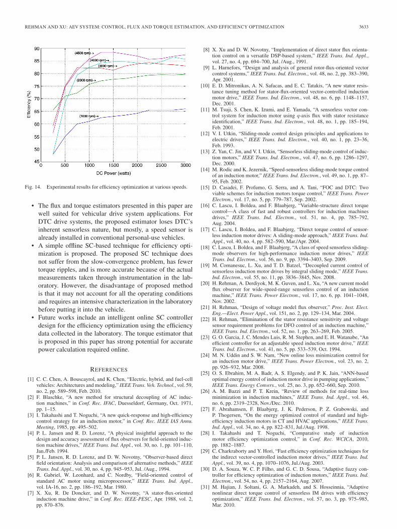
Fig. 12 shows the efficiency optimization at 1000 r/min. Thecommand dc power for battery charging is varied from 250 Wto 3 kW, and ids is iterated for efficiency optimization.Fig. 12(a)–(c) shows the optimized values of ids, the inputmechanical torque, and the shaft input power to achieve thedesired dc output electrical power, respectively. Finally, theefficiency of the drive system is plotted in Fig. 12(d).The efficiency is recorded from the motor shaft to the dc bus,which also includes the inverter efficiency. However, it stillrealizes the optimal flux level for the efficiency maximizationof the machine. In Fig. 13, the flux optimization is demon-strated at speeds of 2000, 3000, 4000, and 4500 r/min. Theoptimum flux current and efficiency are plotted in each tracefor each speed. Fig. 14 shows the combined efficiency plots forthe aforementioned five different speeds for a desired outputelectrical power ranging from 250 W to 3 kW. It is shown thatthe machine efficiency is significantly low when the machineoperates with light load and low speed. This difference could bemuch more significant if the flux optimization is not performedand if the machine is operated all the time at a constant/rated
Fig. 12. Experimental results for efficiency optimization at 1000 r/min.
Fig. 13. Experimental results for efficiency and flux current.
flux. The data plotted in these figures are used in the motorcontroller of HEV/ISA, in which, whenever the torque com-mand changes, the controller will select an appropriate fluxlevel for the efficiency optimization. Although this proposedoffline SC efficiency optimization technique requires a rigorouscharacterization of the machine on the dynamometer, it doesnot suffer from the slow-convergence problem, has fewer torqueripples compared with the online SC method, and is insensitiveto parameters variation, compared with the LMC technique.
V. CONCLUSION
This paper has evaluated the suitability of torque controltechniques for different types of vehicular drive systems and de-signed a flux and torque estimator and an efficiency optimizer.Major conclusions that can be drawn from this paper are listedas follows.
• FOC and DTC are the two main types of control tech-niques. The DTC drive system is more suitable for ISAapplications. For BEV applications, FOC is a preferablechoice over DTC because of torque ripples that producedby DTC. For HEV drive systems, the choice between DTCand FOC depends on the motoring features of ac machineoperation in the steady-state condition.
REHMAN AND XU: AEV SYSTEM: CONTROL, FLUX AND TORQUE ESTIMATION, AND EFFICIENCY OPTIMIZATION 3633
Fig. 14. Experimental results for efficiency optimization at various speeds.
• The flux and torque estimators presented in this paper arewell suited for vehicular drive system applications. ForDTC drive systems, the proposed estimator loses DTC’sinherent sensorless nature, but mostly, a speed sensor isalready installed in conventional personal-use vehicles.
• A simple offline SC-based technique for efficiency opti-mization is proposed. The proposed SC technique doesnot suffer from the slow-convergence problem, has fewertorque ripples, and is more accurate because of the actualmeasurements taken through instrumentation in the lab-oratory. However, the disadvantage of proposed methodis that it may not account for all the operating conditionsand requires an intensive characterization in the laboratorybefore putting it into the vehicle.
• Future works include an intelligent online SC controllerdesign for the efficiency optimization using the efficiencydata collected in the laboratory. The torque estimator thatis proposed in this paper has strong potential for accuratepower calculation required online.
REFERENCES
[1] C. C. Chen, A. Bouscayrol, and K. Chen, “Electric, hybrid, and fuel-cellvehicles: Architectures and modeling,” IEEE Trans. Veh. Technol., vol. 59,no. 2, pp. 589–598, Feb. 2010.
[2] F. Blaschke, “A new method for structural decoupling of AC induc-tion machines,” in Conf. Rec. IFAC, Duesseldorf, Germany, Oct. 1971,pp. 1–15.
[3] I. Takahashi and T. Noguchi, “A new quick-response and high-efficiencycontrol strategy for an induction motor,” in Conf. Rec. IEEE IAS Annu.Meeting, 1985, pp. 495–502.
[4] P. L. Jansen and R. D. Lorenz, “A physical insightful approach to thedesign and accuracy assessment of flux observers for field-oriented induc-tion machine drives,” IEEE Trans. Ind. Appl., vol. 30, no. 1, pp. 101–110,Jan./Feb. 1994.
[5] P. L. Jansen, R. D. Lorenz, and D. W. Novotny, “Observer-based directfield orientation: Analysis and comparison of alternative methods,” IEEETrans. Ind. Appl., vol. 30, no. 4, pp. 945–953, Jul. /Aug., 1994.
[6] R. Gabriel, W. Leonhard, and C. Nordby, “Field-oriented control ofstandard AC motor using microprocessor,” IEEE Trans. Ind. Appl.,vol. IA-16, no. 2, pp. 186–192, Mar. 1980.
[7] X. Xu, R. De Doncker, and D. W. Novotny, “A stator-flux-orientedinduction machine drive,” in Conf. Rec. IEEE-PESC, Apr. 1988, vol. 2,pp. 870–876.
[8] X. Xu and D. W. Novotny, “Implementation of direct stator flux orienta-tion control on a versatile DSP-based system,” IEEE Trans. Ind. Appl.,vol. 27, no. 4, pp. 694–700, Jul. /Aug., 1991.
[9] L. Harnefors, “Design and analysis of general rotor-flux-oriented vectorcontrol systems,” IEEE Trans. Ind. Electron., vol. 48, no. 2, pp. 383–390,Apr. 2001.
[10] E. D. Mitronikas, A. N. Safacas, and E. C. Tatakis, “A new stator resis-tance tuning method for stator-flux-oriented vector-controlled inductionmotor drive,” IEEE Trans. Ind. Electron., vol. 48, no. 6, pp. 1148–1157,Dec. 2001.
[11] M. Tsuji, S. Chen, K. Izumi, and E. Yamada, “A sensorless vector con-trol system for induction motor using q-axis flux with stator resistanceidentification,” IEEE Trans. Ind. Electron., vol. 48, no. 1, pp. 185–194,Feb. 2001.
[12] V. I. Utkin, “Sliding-mode control design principles and applications toelectric drives,” IEEE Trans. Ind. Electron., vol. 40, no. 1, pp. 23–36,Feb. 1993.
[13] Z. Yan, C. Jin, and V. I. Utkin, “Sensorless sliding-mode control of induc-tion motors,” IEEE Trans. Ind. Electron., vol. 47, no. 6, pp. 1286–1297,Dec. 2000.
[14] M. Rodic and K. Jezernik, “Speed-sensorless sliding-mode torque controlof an induction motor,” IEEE Trans. Ind. Electron., vol. 49, no. 1, pp. 87–95, Feb. 2002.
[15] D. Casadei, F. Profumo, G. Serra, and A. Tani, “FOC and DTC: Twoviable schemes for induction motors torque control,” IEEE Trans. PowerElectron., vol. 17, no. 5, pp. 779–787, Sep. 2002.
[16] C. Lascu, I. Boldea, and F. Blaabjerg, “Variable-structure direct torquecontrol—A class of fast and robust controllers for induction machinesdrives,” IEEE Trans. Ind. Electron., vol. 51, no. 4, pp. 785–792,Aug. 2004.
[17] C. Lascu, I. Boldea, and F. Blaabjerg, “Direct torque control of sensor-less induction motor drives: A sliding-mode approach,” IEEE Trans. Ind.Appl., vol. 40, no. 4, pp. 582–590, Mar./Apr. 2004.
[18] C. Lascu, I. Boldea, and F. Blaabjerg, “A class of speed sensorless sliding-mode observers for high-performance induction motor drives,” IEEETrans. Ind. Electron., vol. 56, no. 9, pp. 3394–3403, Sep. 2009.
[19] M. Comanesuc, L. Xu, and T. D. Batzel, “Decoupled current control ofsensorless induction motor drives by integral sliding mode,” IEEE Trans.Ind. Electron., vol. 55, no. 11, pp. 3836–3845, Nov. 2008.
[20] H. Rehman, A. Derdiyok, M. K. Guven, and L. Xu, “A new current modelflux observer for wide-speed-range sensorless control of an inductionmachine,” IEEE Trans. Power Electron., vol. 17, no. 6, pp. 1041–1048,Nov. 2002.
[21] H. Rehman, “Design of voltage model flux observer,” Proc. Inst. Elect.Eng.—Elect. Power Appl., vol. 151, no. 2, pp. 129–134, Mar. 2004.
[22] H. Rehman, “Elimination of the stator resistance sensitivity and voltagesensor requirement problems for DFO control of an induction machine,”IEEE Trans. Ind. Electron., vol. 52, no. 1, pp. 263–269, Feb. 2005.
[23] G. O. Garcia, J. C. Mendes Luis, R. M. Stephen, and E. H. Watanabe, “Anefficient controller for an adjustable speed induction motor drive,” IEEETrans. Ind. Electron., vol. 41, no. 5, pp. 533–539, Oct. 1994.
[24] M. N. Uddin and S. W. Nam, “New online loss minimization control foran induction motor drive,” IEEE Trans. Power Electron., vol. 23, no. 2,pp. 926–932, Mar. 2008.
[25] O. S. Ebrahim, M. A. Badr, A. S. Elgendy, and P. K. Jain, “ANN-basedoptimal energy control of induction motor drive in pumping applications,”IEEE Trans. Energy Convers., vol. 25, no. 3, pp. 652–660, Sep. 2010.
[26] A. M. Bazzi and P. T. Krein, “Review of methods for real-time lossminimization in induction machines,” IEEE Trans. Ind. Appl., vol. 46,no. 6, pp. 2319–2328, Nov./Dec. 2010.
[27] F. Abrahamsen, F. Blaabjerg, J. K. Pederson, P. Z. Grabowski, andP. Thogersen, “On the energy optimized control of standard and high-efficiency induction motors in CT and HVAC applications,” IEEE Trans.Ind. Appl., vol. 34, no. 4, pp. 822–831, Jul./Aug. 1998.
[28] I. Takahashi and T. Noguchi, “Comparative study of inductionmotor efficiency optimization control,” in Conf. Rec. WCICA, 2010,pp. 1882–1887.
[29] C. Charkraborty and Y. Hori, “Fast efficiency optimization techniques forthe indirect vector-controlled induction motor drives,” IEEE Trans. Ind.Appl., vol. 39, no. 4, pp. 1070–1076, Jul./Aug. 2003.
[30] D. A. Souza, W. C. P. Filho, and G. C. D. Sousa, “Adaptive fuzzy con-troller for efficiency optimization of induction motors,” IEEE Trans. Ind.Electron., vol. 54, no. 4, pp. 2157–2164, Aug. 2007.
[31] M. Hajian, J. Soltani, G. A. Markadeh, and S. Hosseinnia, “Adaptivenonlinear direct torque control of sensorless IM drives with efficiencyoptimization,” IEEE Trans. Ind. Electron., vol. 57, no. 3, pp. 975–985,Mar. 2010.

3634 IEEE TRANSACTIONS ON VEHICULAR TECHNOLOGY, VOL. 60, NO. 8, OCTOBER 2011
[32] H. Rehman, “An integrated starter–alternator and low-cost high-performance drive for vehicular applications,” IEEE Trans. Veh. Technol.,vol. 57, no. 3, pp. 1454–1465, May 2008.
[33] H. Rehman and R. J. Hampo, “A flexible high-performance advancedcontroller for electric machines,” in Conf. Rec. IEEE APEC, St. Louis,MO, Feb. 2000, pp. 939–943.
Habib-ur Rehman received the B.Sc. degree inelectrical engineering from the University of Engi-neering and Technology, Lahore, Pakistan, in 1990and the M.S. and Ph.D. degrees in electrical engi-neering from the Ohio State University, Columbus,in 1995 and 2001, respectively.
He has wide experience in power electronics andmotor drives in both industry and academia. FromJuly 1998 to December 1999, he was a DesignEngineer with the Ecostar Electric Drives and FordResearch Laboratory, where he was a Member of
the Electric, Hybrid, and Fuel-Cell Vehicles Development Programs. From2001 to 2006, he was with the Department of Electrical Engineering, UnitedArab Emirates University, Al-Ain, U.A.E., as an Assistant Professor. In 2006,he joined the Department of Electrical Engineering, College of Engineering,American University of Sharjah, Sharjah, U.A.E., where he is currently anAssociate Professor. His research interests include microprocessor/digital-signal-processor-based adjustable-speed drives, power electronics, alternativeenergy vehicles, and renewable energy systems. Currently, he is investigatingthe effective delivery of design skills in engineering education, particularly inelectrical engineering.
Dr. Rehman is the recipient of the Best Teacher Award from the College ofEngineering, UAE University, for the academic year 2002–2003.
Longya Xu (S’89–M’90–SM’93–F’04) received theM.S. and Ph.D. degrees in electrical engineeringfrom the University of Wisconsin, Madison, in 1986and 1990.
In 1990, he joined the Department of Electricaland Computer Engineering, the Ohio State Uni-versity (OSU), Columbus, where he is currently aProfessor. He has served as a Consultant to sev-eral industrial companies, including the RaytheonCompany, Boeing, Honeywell, GE Aviation, the U.S.Wind Power Company, General Motors, Ford, and
Unique Mobility Inc., for various industrial concerns. He is currently theDirector of the newly established Center of High Performance Power Elec-tronics, OSU, which is supported by the Ohio Third Frontier Program. Hisresearch and teaching interests include the dynamics and optimized design ofspecial electrical machines and power converters for variable-speed systems,the application of advanced control theory and digital signal processors formotion control, and distributed power systems in super high-speed operations.Over the past 20 years, he has conducted several research projects on electricaland hybrid electrical vehicles and variable-speed constant-frequency windpower generation systems.
Dr. Xu is currently a Member-at-Large for the IEEE Industry ApplicationsSociety (IAS) Executive Board. He has served as the Chair of the ElectricMachine Committee of the IEEE IAS and an Associate Editor for the IEEETRANSACTIONS ON POWER ELECTRONICS. He received the First Prize PaperAward from the Industry Drive Committee of the IEEE IAS in 1990, theResearch Initiation Award from the National Science Foundation in 1991 forhis work on wind power generation, and the Lumley Research Award from theCollege of Engineering, OSU, in 1995, 1999, and 2004, for his outstandingresearch accomplishments.

![UITP December 13 2013 [Compatibiliteitsmodus]213.191.137.190/Dokumenti/CTIF/Odbor_CTIF/CTIF_Commission_Ext… · (alternative) fuel(s)/drive train(s) are used in vehicles involved](https://img.pdfslide.net/doc/110x75/5f4a66c477c0bb06905ea6f3/uitp-december-13-2013-compatibiliteitsmodus213191137190dokumentictifodborctifctifcommissionext.jpg)