Embed Size (px)
Citation preview
Alternative Systems for
the Performance Standard for
Protective Coatings
Presented by:
Peter D. McNulty
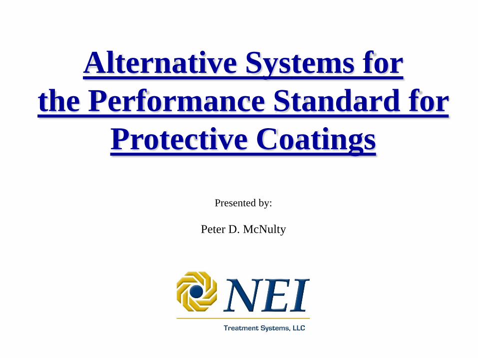
IMO Ballast Tank PSPC
• Extensive Documentation
• Tedious Preparation
• Difficult Application Conditions(e.g. humidity)
• Extensive Inspections (VLCC will have 50,000 inspection points)
• 2 Epoxy Coats w 320 um DFT
• Goal is 15 Years in “Good” Condition
• Expected to add 2 – 5% to Newbuild Cost
• Expected to Reduce Shipyard Productivity, AND…
IMO Ballast Tank PSPC
“Invites Governments to
encourage the development of
novel technologies aimed at
providing for Alternative Systems
and to keep the Organization
advised of any positive results.”
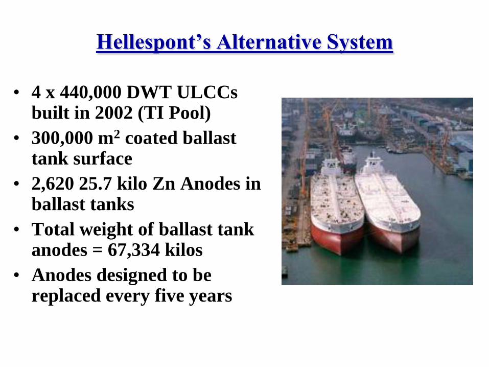
Hellespont’s Alternative System
• 4 x 440,000 DWT ULCCs built in 2002 (TI Pool)
• 300,000 m2 coated ballast tank surface
• 2,620 25.7 kilo Zn Anodes in ballast tanks
• Total weight of ballast tank anodes = 67,334 kilos
• Anodes designed to be replaced every five years
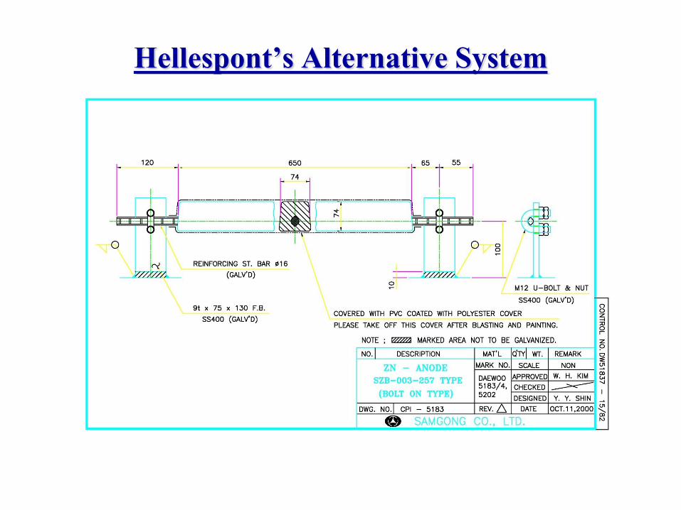
Hellespont’s Alternative System
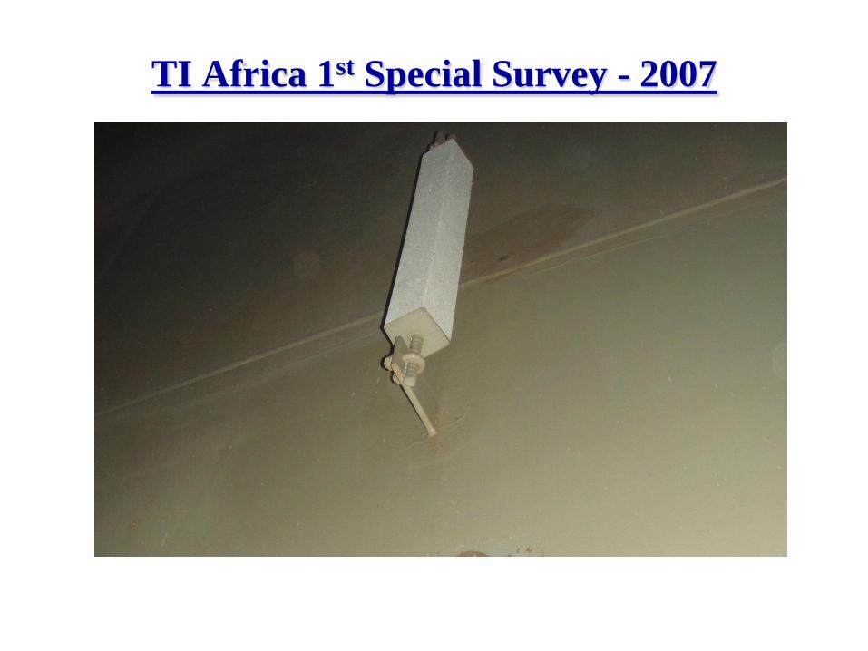
TI Africa 1st Special Survey - 2007
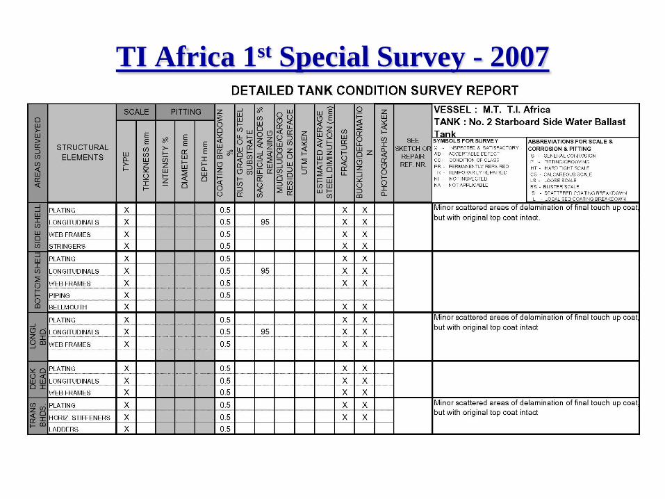
TI Africa 1st Special Survey - 2007
TI Africa 1st Special Survey - 2007
• CP Anodes Designed for 10% Remaining After 5
Years, but They Are 95% Intact
• Coating Breakdown Designed for 5% After 5 Years,
but Only 0.5% Breakdown Observed
• No note of observed rust staining in ballast tanks.
• ABS Surveyor stated that he had never seen ballast
tanks in such pristine condition after 5 years.
• How?
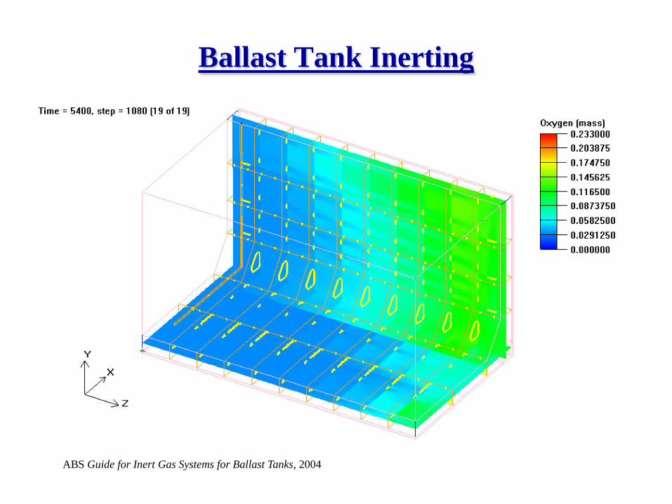
Ballast Tank Inerting
ABS Guide for Inert Gas Systems for Ballast Tanks, 2004
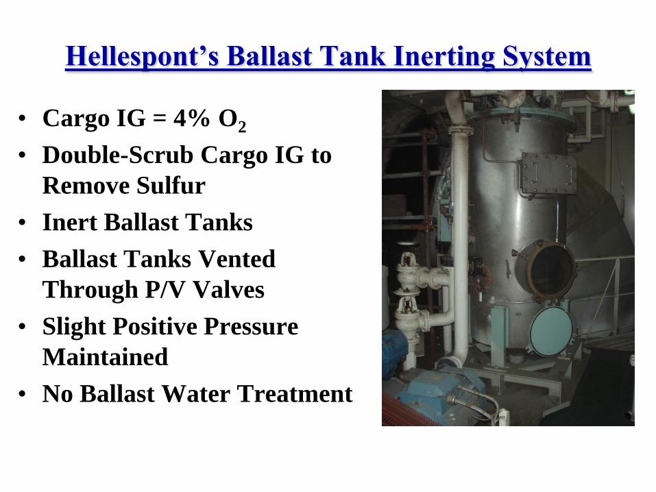
Hellespont’s Ballast Tank Inerting System
• Cargo IG = 4% O2
• Double-Scrub Cargo IG to
Remove Sulfur
• Inert Ballast Tanks
• Ballast Tanks Vented
Through P/V Valves
• Slight Positive Pressure
Maintained
• No Ballast Water Treatment
Why Is Such A System Needed?
• Sacrificial anodes only work when ballast tanks are full
• New design makes most cargo vessels double-hull with far
more (up to 5x) ballast tank surface area
• In double-hull vessels much of early ballast tank coating
breakdown results from impact damage from tugs, fenders,
floating debris, and (in bulkers) clamshell buckets
• Atmospheric conditions inside empty ballast tanks are often
above the dew point, resulting in a thin film of salt water and
high corrosion rate (well above CSR est. 0.2 mm/yr)
• Corrosion doesn’t just follow coating failure, corrosion
causes coating failure
• PSPC is expected to be expensive to implement
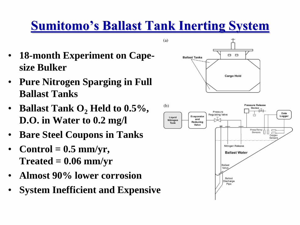
Sumitomo’s Ballast Tank Inerting System
• 18-month Experiment on Cape-
size Bulker
• Pure Nitrogen Sparging in Full
Ballast Tanks
• Ballast Tank O2 Held to 0.5%,
D.O. in Water to 0.2 mg/l
• Bare Steel Coupons in Tanks
• Control = 0.5 mm/yr,
Treated = 0.06 mm/yr
• Almost 90% lower corrosion
• System Inefficient and Expensive
OceanSaver apparently has
positive test results also.
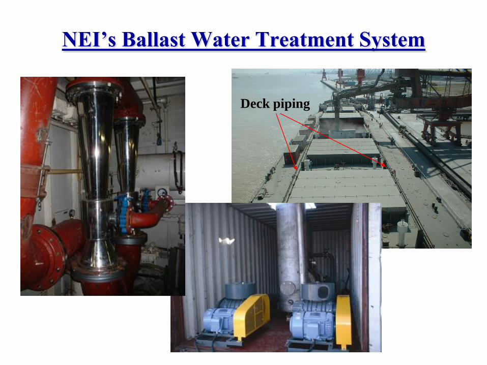
NEI’s Ballast Water Treatment System
Deck piping
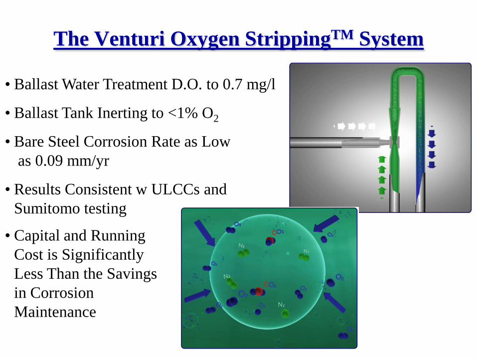
The Venturi Oxygen StrippingTM System
• Ballast Water Treatment D.O. to 0.7 mg/l
• Ballast Tank Inerting to <1% O2
• Bare Steel Corrosion Rate as Low
as 0.09 mm/yr
• Results Consistent w ULCCs and
Sumitomo testing
• Capital and Running
Cost is Significantly
Less Than the Savings
in Corrosion
Maintenance
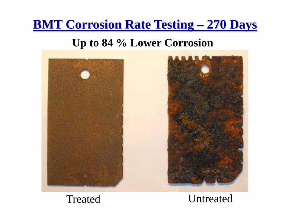
BMT Corrosion Rate Testing – 270 Days
Up to 84 % Lower Corrosion
Treated Untreated
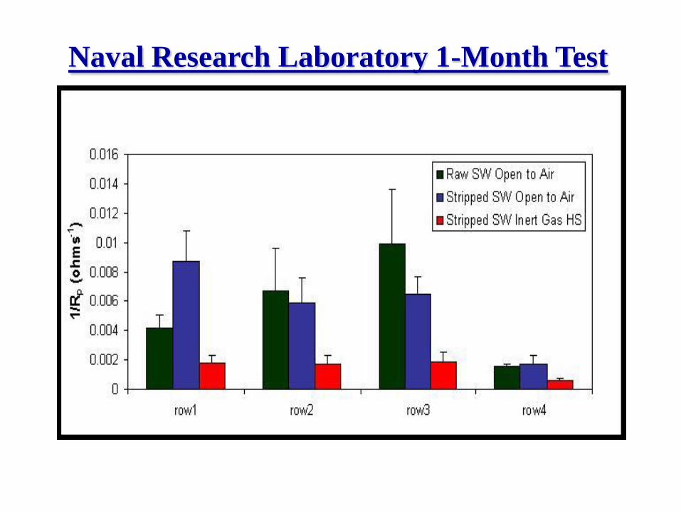
Naval Research Laboratory 1-Month Test
From 1 Month to 5 Years, Similar Results
• Shipboard Results are Better than Laboratory Testing
• Corrosion Reduction from 80 to 95 Percent
• The Longer the Trial the Better the Results
• “Aqueous corrosion of steels in natural waters
depends entirely upon the availability of
oxygen.” (ISSC 2005)
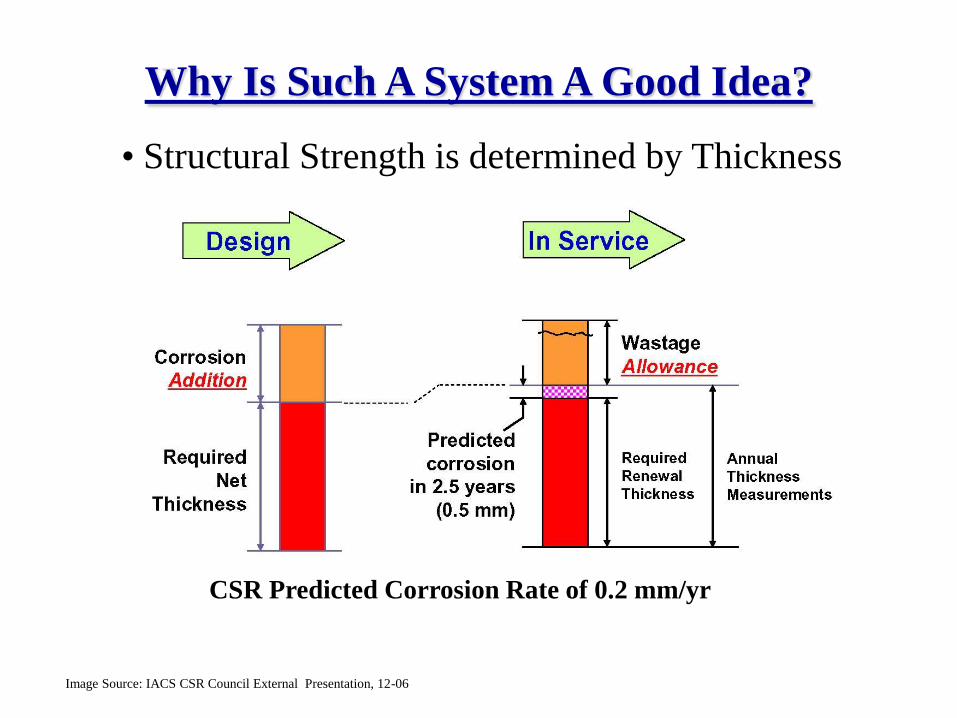
Why Is Such A System A Good Idea?
CSR Predicted Corrosion Rate of 0.2 mm/yr
Image Source: IACS CSR Council External Presentation, 12-06
• Structural Strength is determined by Thickness
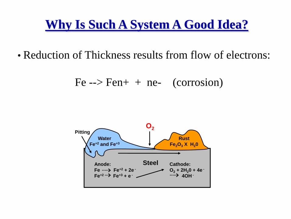
Why Is Such A System A Good Idea?
PittingO2
Anode:
Fe Fe+2 + 2e -
Fe+2 Fe+3 + e -
Cathode:
O2 + 2H20 + 4e -
4OH -
Steel
Water
Fe+2 and Fe+3
Rust
Fe2O3 X H20
• Reduction of Thickness results from flow of electrons:
Fe --> Fen+ + ne- (corrosion)
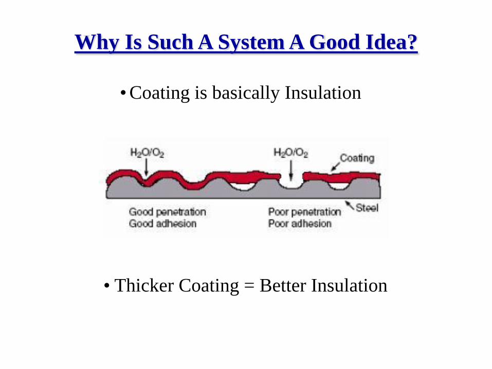
Why Is Such A System A Good Idea?
• Coating is basically Insulation
• Thicker Coating = Better Insulation
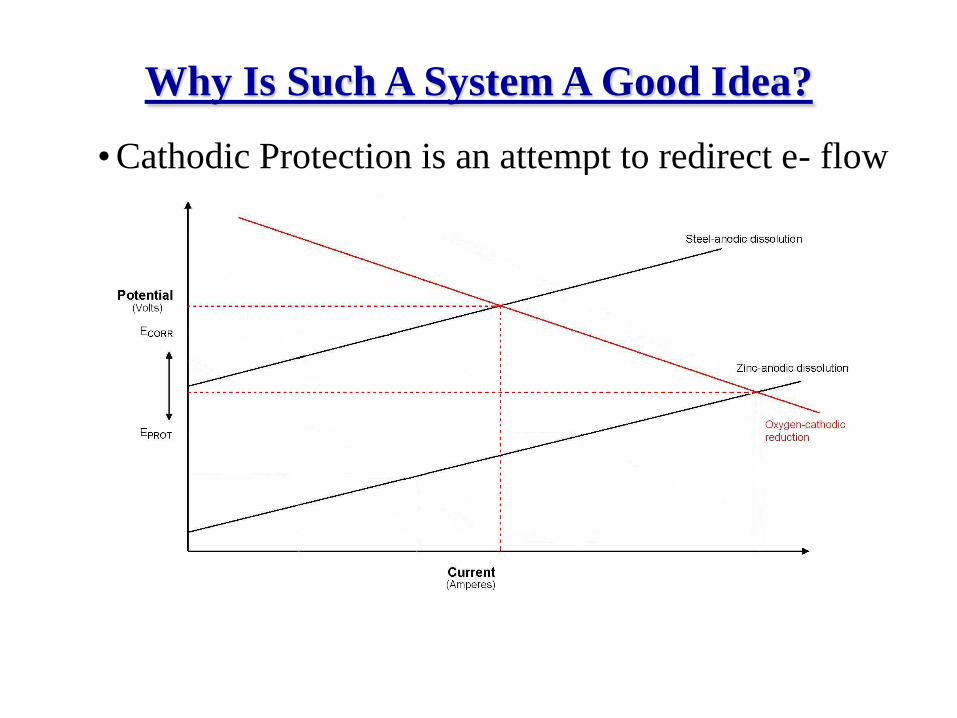
Why Is Such A System A Good Idea?
• Cathodic Protection is an attempt to redirect e- flow
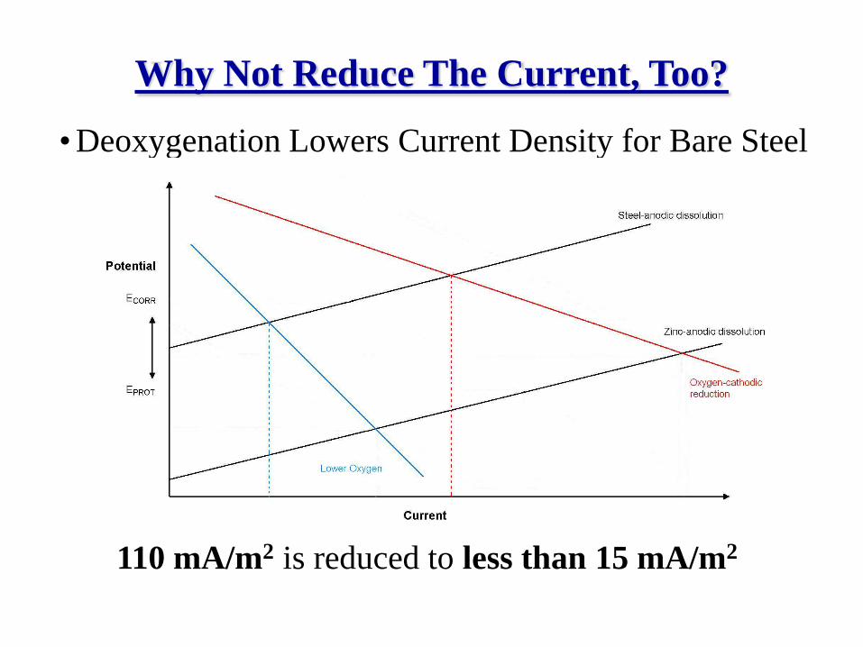
Why Not Reduce The Current, Too?
• Deoxygenation Lowers Current Density for Bare Steel
110 mA/m2 is reduced to less than 15 mA/m2
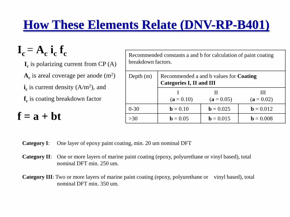
How These Elements Relate (DNV-RP-B401)
Ic = Ac ic fc
Ic is polarizing current from CP (A)
Ac is areal coverage per anode (m2)
ic is current density (A/m2), and
fc is coating breakdown factor
f = a + bt
Recommended constants a and b for calculation of paint coating
breakdown factors.
Depth (m) Recommended a and b values for Coating
Categories I, II and III
I II III
(a = 0.10) (a = 0.05) (a = 0.02)
0-30 b = 0.10 b = 0.025 b = 0.012
>30 b = 0.05 b = 0.015 b = 0.008
Category I: One layer of epoxy paint coating, min. 20 um nominal DFT
Category II: One or more layers of marine paint coating (epoxy, polyurethane or vinyl based), total
nominal DFT min. 250 um.
Category III: Two or more layers of marine paint coating (epoxy, polyurethane or vinyl based), total
nominal DFT min. 350 um.
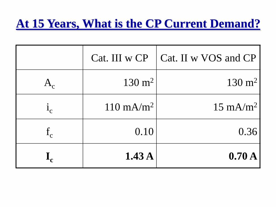
At 15 Years, What is the CP Current Demand?
Cat. III w CP Cat. II w VOS and CP
Ac 130 m2 130 m2
ic 110 mA/m2 15 mA/m2
fc 0.10 0.36
Ic 1.43 A 0.70 A
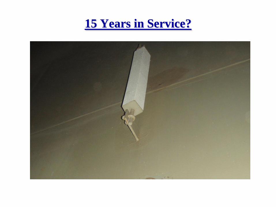
15 Years in Service?
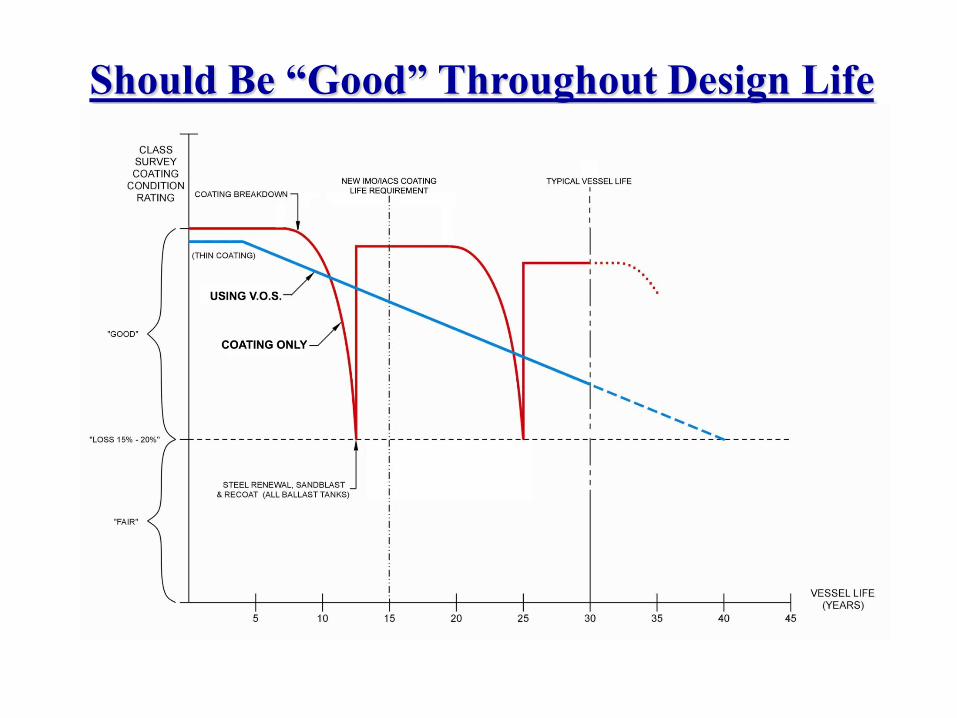
Should Be “Good” Throughout Design Life
www.nei-marine.com
Ballast Tank Deoxygenation Can
Reduce Life Cycle Cost