Embed Size (px)
Citation preview

Alternators and Starters(Correct) Diagnosis; Beyond the Quick‐Test …

“Electrical Challenges”

Electrical Diagnostics Is Challenging
Lack of understanding of this topic is the monkey on many technician's backSuper techs understand this topic very well!

Case Study:
2001 Monte Carlo Intermittent AC operation 3.8 ‐ V6 ‐manual AC ‐ 150,000 miles Previous repairs New AC condenser, hoses, pressure sensors Multiple recharges, new control head New clutch, new compressor, rewire clutch
Never able to duplicate in shop……..

Recorded Scan Data
AC request Yes
A/C relay command Off
A/C off for WOT No
Coolant temp 198⁰
A/C high side pressure sensor 210 psi
FC relay 1 command Yes

BCM Data Recording
During failure No A/C PID in BCM However BCM data did indicate “load shed level 2”
Only bi‐directional control available is A/C clutch function
HVAC controls are manual What would the next diagnostic step be?

Research “Load Shedding”:
Used by GM in standard and RVC systems Will selectively turn accessories down or off to help maintain battery state of charge (S.O.C.)
Based on: OCV at engine off and start‐up Battery temp Charge rate voltage

Load Shedding Strategy:
Power mode module Typically the BCM Can be the DIM or other modules
Monitors: Charge rate Battery voltage KOEO Calculates battery temperature from IAT

Load Shedding Strategy:
Determines that the battery will drop below 80% SOC Idle speed will increase Non‐critical loads will be cycled off in 2 ‐ 3 stages
Increases charge rate and decrease load This strategy does not have direct control over alternator function

Load Shed Level One

Load Shed Level Two
Load Shed Level Two

Load Shed Level Counter
22
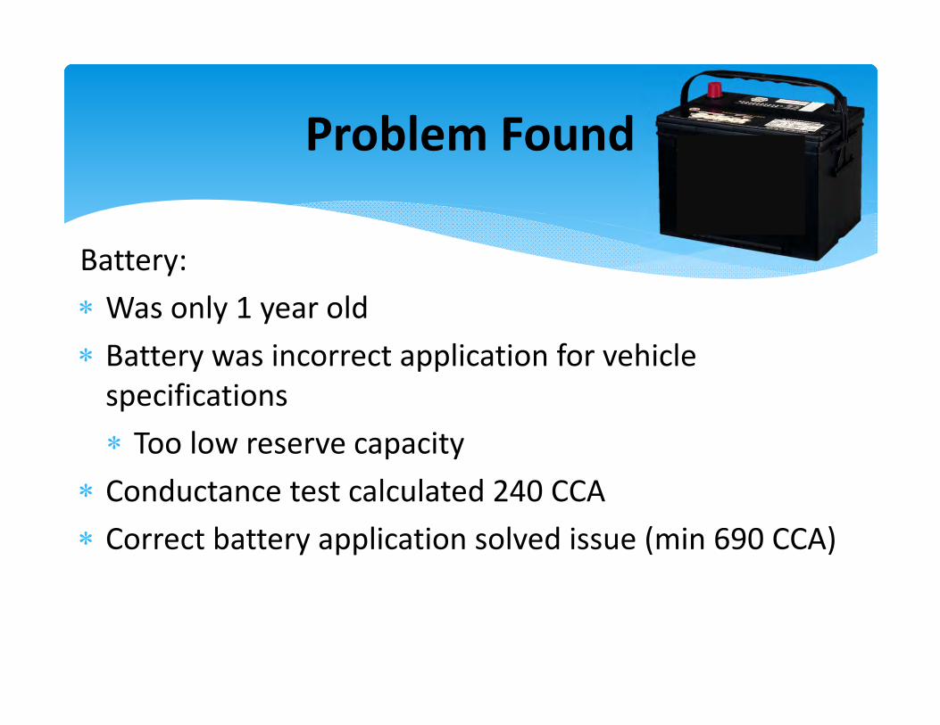
Problem Found
Battery: Was only 1 year old Battery was incorrect application for vehicle specifications Too low reserve capacity
Conductance test calculated 240 CCA Correct battery application solved issue (min 690 CCA)


It All Starts Here . . .
• Cranking current– Will it provide the necessary current?
• Cranking voltage– Above the minimum voltage requirement?
• Ability to charge– Will it recover?
• Reserve capacity– How long will it do all of the above?

Ratings
CCA “Cold Cranking Amps” Amps for 30 seconds at 0° F while maintaining post voltage of 7.2 v
CA “Cranking Amps” Same as CCA except it is measured at 32° F “Better marketing”
RC “Reserve Capacity” Minutes the battery will deliver 25 amps and still maintain A post voltage of 10.5 v
A/H “Amp Hour” Measures low current draw for 20 hours while maintaining A minimum voltage of 10.5 volts at 70° F

Temperature Plays A Role:
Normal cranking loads in moderate temps can require 125 ‐ 200 amps or more
At 0° F, that number increases 200 ‐ 250% At 0° F, most batteries can only deliver about 65% of their normal cranking amps

“FLA” vs “AGM” Batteries
Traditional automotive batteries are “FLA” type (flooded lead acid)
Newer tech choice may be AGM (absorbent glass mat), either spiral wound, or flat plate Longer lasting Higher performance More compact for given performance Must be kept at higher SOC No liquid, spill proof AGM Type
FLA Type

Testing “AGM” Batteries
AGM batteries must be tested with “conductance” testing Lead adapters must be used for accurate results
Steel bolts will disrupt conductance frequencies
No load testing (carbon pile). This type of testing can damage AGM batteries

Charging AGM Batteries
AGM batteries must be charged with voltage regulated chargers Standard high voltage chargers can damage AGM batteries
Charging voltage must be within 14.1 – 14.8 volts DC max

Charging AGM Batteries
AGM batteries must be charged with voltage regulated chargers Able to accept higher charging current than FLA
Must not allow to overheat when charging, damage will result

Don’t Rush It !Keep Battery Temp Below 125°
Don’t Rush It !

Battery State Of ChargeState Of Charge Open Circuit Voltage Specific Gravity
100% 12.6 Or Greater 1.265
75% 12.4 1.225
50% 12.2 1.190
25% 12.0 1.155
0% 11.7 Or Less 1.120 Or Lower
• State Of Charge voltages Change With Temperature
• At 0° F, A Lead Acid Battery Operates @ 40% Of Capacity
v

GoodWell defined imprint suggests A good cable to post connection
BadLack of imprint suggests A poor cable to post connection
Check bolt length
Check spacer condition
Battery Connections Are Important
Which one of theses has the signs of A good connection?

Connections Are Critical For Accurate Testing
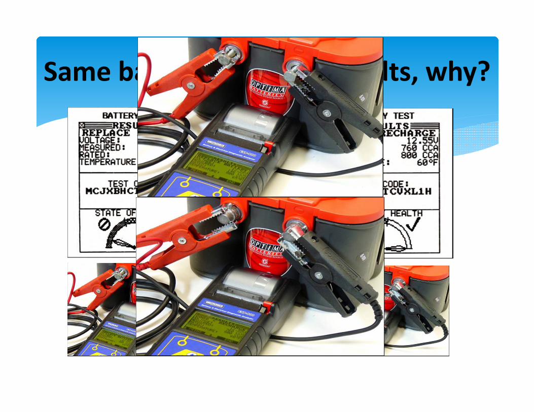
Same battery different results, why?

Battery Replacement Reset Procedures
This information details when and how to reset electrically operated components, accessories and modules for vehicles that have had battery service, replacement or loss of electrical power. Coverage is for U.S. domestic and import vehicles introduced or revised from the period 2000 – present (partial coverage from 1991 – 1999).

Battery Replacement Reset Procedures
Specifics include:Battery disconnection precautionsPower windows, locks and sunroof programming
Convenience accessory programmingSupplemental restraint, ABS system precautions
Engine and body control system resettingMain and auxiliary battery location illustrations
Illustrated hood and trunk release methods

Battery Reset Tool
Late model Fords including F‐Series trucksLate model BMWLate model Mini Cooper And more..


Voltage Drop Testing

Common Voltage Terminology
Open circuit voltage = potential voltage of a unloaded power circuit
Closed circuit voltage = voltage reading of a loaded circuit Is there a “voltage differential” Why?
Load

Voltage Testing “Voltage drop” testing Measurement of voltage differential between two points in circuit
Voltage must be measured while system is under load
Under Load

Negative Test Points During Crank

Excessive Negative Voltage Drop
Look for looseness or corrosion @ battery post to cable connection
Loose or corroded cable connection at the engine block Connections or starter mount

Battery Positive Voltage Drop
Battery positive post to the starter positive stud Disable fuel or ignition Crank engine Voltage drop should be .2 volts or less for cables under 36 inches in length .3 volts or less for cables over 36 inches in length .2 volts through a switch or relay .3 volts through a solenoid

Positive Test Points During Crank
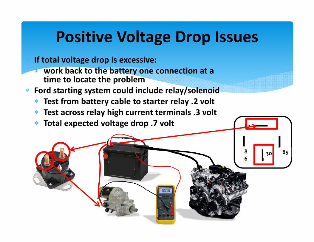
Positive Voltage Drop Issues If total voltage drop is excessive: work back to the battery one connection at a time to locate the problem
Ford starting system could include relay/solenoid Test from battery cable to starter relay .2 volt Test across relay high current terminals .3 volt Total expected voltage drop .7 volt 87
30 8586

Charging Diagnostics

Charge Rate

Output Voltage Testing
Generic spec 1.5 to 2 volts above open circuit voltage at high idle (at 70 degrees)
Colder temperatures should cause higher regulator set point
Is that a “fits all” spec? 1998 Accord = 13.5 volts @ normal engine temp 2010 Yukon = 12.6 to 15.0 volts @ 2,500 RPM 2008 Mustang = 13.2 to 15.5 volts @ 2,000 RPM

Crank Voltage
Stable Cranking Voltage For 15 Sec

Crank & Charge Voltage
OCV
Cranking
Chg Rate

Current Hit
150 Amps
WOW!
That Explains The Sharp Drop In Voltage

Changing Loads
Load ON Load Off

OK, Now What?
We have proven: We have good output and regulation W/no load We have good output and regulation loaded Regulation responds when loads are removed We probably do not have any excessive resistance in the circuit
But what if the results aren’t so good? Failed or marginal alternator Failed or marginal regulator or control circuit Excessive voltage drop in the output circuit

Voltage Drop For Resistance
Run @ 2,000 RPM W/loads ON Measure voltage drop from positive alternator output post to positive battery post (if available)
Measure voltage drop from the rear ½ of the alternator case to the battery negative post (if available)
Neither reading should exceed .2 volts Any higher indicates high resistance in the output circuit

2001 F‐150
• This is the wiring for our test vehicle
• Take a moment to trace the output wiring to see what the current path is to the battery and to the systems on the vehicle

2001 F‐150
• This is the wiring for our test vehicle
• Take a moment to trace the outputwiring to see what the current path is to the battery and to the systems on the vehicle
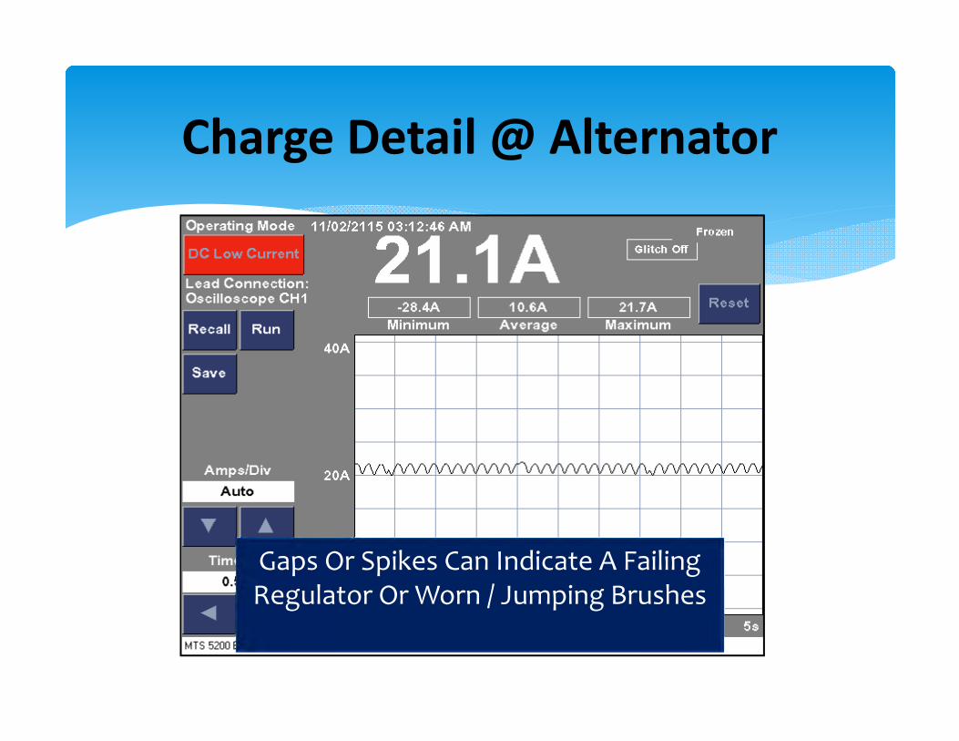
Charge Detail @ Alternator
Gaps Or Spikes Can Indicate A Failing Regulator Or Worn / Jumping Brushes
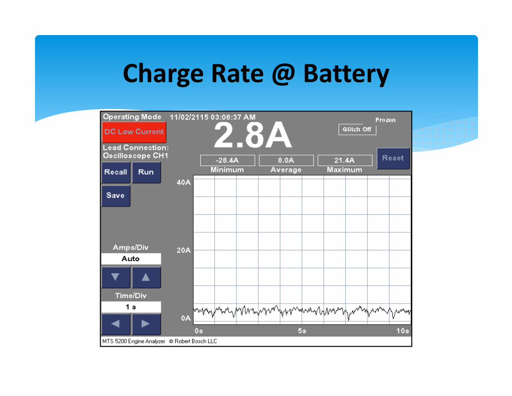
Charge Rate @ Battery

Voltage Quality
One of the most overlooked problems for intermittent drivability issues
A scope is the best way to test Set on AC coupling Turn filter ON
A DVOM set on AC voltage is better than not testing Should see less than 300 mv AC

Normal Scope Ripple
The Cursors Measure About 200 mV Peak To Peak

DVOM Ripple Test

Don’t replace that Alternator just yet !
Starting with the 2005 model year Regulated voltage control (RVC) system. RVC reduces the targeted output voltage to 12.6‐13.1 volts when in fuel economy mode to improve fuel economy.

Little Known Fact:
The generator may exit “ECON” mode if additional voltage is required. This causes the voltmeter to fluctuate between 12 and 14 volts

Integrated RVC and stand‐alone RVC (SARVC).
Diagnostics are specific for each vehicle that uses this system.

Diagnostics are specific for each vehicle that uses this system
Integrated RVC And Stand‐alone RVC (SARVC).

Cooling is Essential

Automatic Tensioners
Maintains proper tension for the life of the belt Reduce maintenance Eliminates the need to manually re‐tension belts
Provide consistent and correct belt tension Increases accessory bearing life
Prevent belt slip Reduces noise Increases service life Ensures proper accessory function

Not Just Tension

Decoupler Pulleys
Replaced As A Unit Special Tools Required Do Not Substitute A Solid Pulley

Solid vs. One Way vs. Decoupler

Stretch Belts
Used on 2 pulley systems One time use No tensioner Requires special installation tool

Tool In Use
Cut it off, roll it on