Embed Size (px)
Citation preview

Altitude Estimation and Control of anInsect-Scale Robot with an Onboard ProximitySensor
E. Farrell Helbling, Sawyer B. Fuller, and Robert J. Wood
Abstract Insect-scale micro-air vehicles (MAVs) require careful consideration ofthe size, weight and power for each component. The inherent instability of the sys-tem, exacerbated by the faster dynamics that result from increasing angular accel-erations with decreasing scale, requires high bandwidth sensing to maintain sta-ble flight. The Harvard RoboBee is the first MAV under 100 mg to demonstratecontrolled flight using external motion capture cameras to measure the positionand orientation of the vehicle during flight. Prior research into onboard sensinghas demonstrated several sensors that provide sufficiently high-bandwidth and low-latency feedback to stabilize the attitude of the robot. To achieve autonomous flight,the vehicle needs to sense its attitude, altitude, and either lateral position or velocity.Here we build on previous work by incorporating a sensor that is size- and power-compatible with insect-scale flight, capable of estimating distance by measuring thetime-of-flight of an infrared laser pulse. This sensor has sufficiently low latencyto allow the robot to maintain constant altitude over multiple flight experiments.This work on onboard altitude control represents the latest results in achieving au-tonomous control and visually-guided flight.
1 Introduction
Insect-scale MAVs (50-500 mg) are envisioned for many applications, includinghazardous environment exploration and assisted agriculture. However, flight at thisscale poses a control challenge for stability, as rotational acceleration increases witha decrease in the vehicle’s characteristic length, scaling as l�1 [15]. The vehicle’sflight dynamics are also unstable, requiring the flight controller to perform contin-
E. Farrell Helbling, Sawyer B. Fuller, and Robert J. WoodHarvard University John A. Paulson School of Engineering and Applied Sciences and the WyssInstitute for Biologically-Inspired Engineering, 60 Oxford Street, Cambridge, MA 02138 USA,e-mail: [email protected]
1

2 E. Farrell Helbling, Sawyer B. Fuller, and Robert J. Wood
Fig. 1 The Harvard RoboBeeis an 80 mg flapping-wingMAV that has demonstratedcontrolled flight using exter-nal motion capture camerasand reflective markers onthe base and nose of therobot. Here we incorporatean infrared (IR) time-of-flight(ToF) sensor mounted on thebase of the robot and useit to detect and control dis-tance from the ground duringflight. Inset: VL6180x (STMicroelectronics) mountedon a custom flex circuit. Thesensor is 5 mm in length.
uous corrective maneuvers [1]. Therefore, in addition to meeting the stringent massand power requirements for vehicles at this scale, onboard sensors must also providelow latency, high bandwidth information to the active controller.
The Harvard RoboBee (see Fig. 1) is the first MAV under 100 mg to lift its ownweight and demonstrate controlled flight under external power [16]; however, an ex-ternal, camera-based motion capture system (Vicon T040 System, Oxford UK) wasused to estimate the position and orientation of the robot. For the RoboBee to oper-ate in unstructured environments, it must be equipped with sensors that can estimatethe vehicle’s state to stabilize the dynamics and sense its external environment. In-sects are a key source of inspiration for flight control, they rely on a multitude ofsensory organs that provide estimates of relevant state variables to use in combi-nation with reflexive or high-level control architectures to adjust flight accordingly[21].
Vision has been shown to be particularly important for navigation at small scales;GPS is too imprecise, with an accuracy of 1-10 m, and currently available emissivesensors such as radar, scanning laser rangefinders, and sonar do not meet the weightrequirements (⇠40 mg) of the vehicle [4]. MAVs have adopted vision sensors fornavigation at scales one to two orders of magnitude larger than the RoboBee, includ-ing [7] and [3]. Other researchers have demonstrated high bandwidth, low latency,and lightweight biomimetic optical sensors with the goal of stabilizing many aspectsof the RoboBee’s flight, including altitude on fixed guide wires [9], and orientationafter takeoff [11].
In addition to these vision-based sensors, inertial measurement units (IMUs) – asystem consisting of gyroscopes, accelerometers, and magnetometers – have longbeen used for flight control and stabilization of larger aircraft. Demand for minia-turization by the consumer electronics industry has resulted in sensors that nowmeet the mass (⇠ 10-100 mg) and power (⇠10 mW) requirements of the RoboBeeand have been integrated onto the vehicle. These sensors demonstrated low-latencyfeedback and sufficient noise rejection, controlling motion about the pitch and yaw

Altitude Control of an Insect-Scale MAV 3
Fig. 2 Model of the altitudedynamics of the RoboBee anddiagram of the flight appa-ratus. The altitude controllerassumes upright orientation,reducing the model to a sin-gle dimension, z. The thrustforce, FT , generated by theflapping wings acts along thebody z�axis, with the gravita-tional force of the body actingat the center of mass. Therobot moves with velocity, z,along the z�axis. The sensor(mounted below the robot)estimates the distance of therobot from the ground, z, withVicon cameras estimating thelateral position and attitudeduring flight. The robot istethered for power and con-trol signals, as well as sensorcommunications.
z
mg
FT
x y
z
laser
ToF Range Sensor
z
axes [12], as well as providing flight stabilization at takeoff and hovering [10]. Inaddition to stabilizing the attitude of the vehicle, the hovering controller from [6]requires estimates of rotation rate about the body axes, the absolute orientation ofthe vehicle, the lateral velocity and position, as well as the altitude to hover withasymptotic stability.
In addition to facilitating altitude regulation, an altitude estimate, when combinedwith other sensors, can be used to estimate other aspects of the vehicle’s motion.Future research into autonomous, visually-guided flight at this scale will require ac-curate altitude estimation. An onboard, downward-facing optic flow sensor coupledwith an absolute altitude estimate can provide the vehicle’s forward velocity, as in[13] and demonstrated by landing honeybees in nature [21].
Here we consider a millimeter-scale infrared (IR) time-of-flight (ToF) sensor tomeasure the absolute position of the vehicle from the ground. We demonstrate thatthe sensor meets the mass and power requirements of the vehicle while providingfeedback at a sufficient rate (⇠50 Hz) to control the altitude of the vehicle duringhovering flight.
This paper describes the altitude dynamics of the RoboBee and estimates theminimum feedback rate necessary to stabilize this degree of freedom (Sect. 2); dis-cusses the sensors that meet the mass, power, and frequency requirements as wellas describes the integration and calibration of the ToF sensor onboard the vehicle(Sect. 3); and demonstrates controlled flight of the vehicle with onboard altitudeestimates from the sensor at multiple setpoints (Sect. 4).

4 E. Farrell Helbling, Sawyer B. Fuller, and Robert J. Wood
PID Controller RoboBee Dynamics Sensor Dynamics Filter
F(s)=ki + kps+ kds2
sG(s)=
1ms(s+b)
H(s)= 1ts+1e�td s
d zz
Fig. 3 The closed-loop dynamic model of the robot and sensor for perturbations away from thehovering setpoint. The PID controller (gains kp, ki, kd) computes a thrust force FT that minimizeserror between the desired setpoint zd and the measured altitude z. This thrust force acts as an inputto the dynamics of the robot (Eq. 1), forcing the robot to a new altitude. The sensor reads thisnew altitude with some time delay td and this response is filtered with a low pass filter with cutofffrequency fc = 20 Hz.
2 Altitude Dynamics
The RoboBee used in these experiments was first presented in [17]. Piezoelectricactuators drive each of the wings, and the system has been shown to produce liftand body torques to take off, land, hover and perform aggressive maneuvers [6].The hovering controller is composed of three sub-controllers – the lateral controller,the attitude controller, and the altitude controller. In this work, we eliminate the needfor an altitude estimate from Vicon by providing it instead from an onboard sensor(see Fig. 2).
The altitude controller assumes that the robot is always in the upright orientation– an assumption that is maintained by the attitude controller. This requires that thethrust vector is always aligned with the z�axis, along the same axis as the gravita-tional force. Assuming that the robot maintains an attitude that is nearly upright, thecontroller can be designed around a linearization of its dynamics at hover, neglectingsecond-order effects arising from perturbations from zero attitude.
An understanding of the vehicle dynamics along the body z�axis is required todetermine the maximum latency (sensor time delay) permissible for altitude control.The altitude dynamics can be described by a linear, second-order system:
z =FT
m�bz�g , (1)
where FT is the thrust force, m is the mass of the robot (m = 110⇥10�6 kg), b is thedamping constant (b = 1.2 s�1 [5]), and g is the gravitational acceleration.
To determine the maximum latency in sensor estimates, we computed the closedloop poles of the system and determined the maximum settling time. The altitudecontroller is a proportional-integral-derivative (PID) controller that reduces errorbetween a desired setpoint and the measured height of the robot. A feedforwardterm in the controller balances the gravitational force, and thus the input is the thrustforce. The sensor latency is modeled using a second-order Pade approximation ofpure time delay, and the raw sensor data is processed with a low-pass filter ( fc =20 Hz). We simulated multiple time delays in the range td = 0.01 – 0.5 s (see Fig. 3).
Altitude Control of an Insect-Scale MAV 5
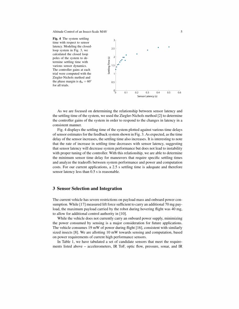
Fig. 4 The system settlingtime with respect to sensorlatency. Modeling the closed-loop system in Fig. 3, wecalculated the closed looppoles of the system to de-termine settling time withvarious sensor dynamics.The controller gains at eachtrial were computed with theZiegler-Nichols method andthe phase margin is fm = 60�for all trials.
0 0.1 0.2 0.3 0.4 0.5 0.60
0.5
1
1.5
2
2.5
3
Sett
ling
Tim
e (s
)
Sensor Latency (s)
As we are focused on determining the relationship between sensor latency andthe settling time of the system, we used the Ziegler-Nichols method [2] to determinethe controller gains of the system in order to respond to the changes in latency in aconsistent manner.
Fig. 4 displays the settling time of the system plotted against various time delaysof sensor estimates for the feedback system shown in Fig. 3. As expected, as the timedelay of the sensor increases, the settling time also increases. It is interesting to notethat the rate of increase in settling time decreases with sensor latency, suggestingthat sensor latency will decrease system performance but does not lead to instabilitywith proper tuning of the controller. With this relationship, we are able to determinethe minimum sensor time delay for maneuvers that require specific settling timesand analyze the tradeoffs between system performance and power and computationcosts. For our current applications, a 2.5 s settling time is adequate and thereforesensor latency less than 0.5 s is reasonable.
3 Sensor Selection and Integration
The current vehicle has severe restrictions on payload mass and onboard power con-sumption. While [17] measured lift force sufficient to carry an additional 70 mg pay-load, the maximum payload carried by the robot during hovering flight was 40 mg,to allow for additional control authority in [10].
While the vehicle does not currently carry an onboard power supply, minimizingthe power consumed by sensing is a major consideration for future applications.The vehicle consumes 19 mW of power during flight [16], consistent with similarlysized insects [8]. We are allotting 10 mW towards sensing and computation, basedon power requirements of current high performance sensors.
In Table 1, we have tabulated a set of candidate sensors that meet the require-ments listed above – accelerometers, IR ToF, optic flow, pressure, sonar, and IR

6 E. Farrell Helbling, Sawyer B. Fuller, and Robert J. Wood
Table 1 Altitude sensors for Centimeter-Scale Flapping-Wing MAVs
Sensors Mass Power Frequency Remarks
Accelerometer [10] 24 mg 1 mW 1 kHz Integration drift (2 m in 1 s)Time-of-Flight [18] 20 mg 6 mW 50 Hz VCSEL light source requires regulatorOptical Flow [9] 15 mg 15 mW 40 Hz Computationally expensivePressure [20] 40 mg 3 mW 125 Hz Insufficient resolution (20 cm)Sonar [19] 80 mg 10 mW 40 Hz Does not meet mass constraintsIR Range [14] 16 mg 6 mW 10 Hz Dependent on reflective material
range detectors – that are currently available. Our evaluation is as follows: ac-celerometers lose accuracy over time due to the drift in sensor estimate after inte-gration; additional velocity or distance sensors would need to be integrated onboardthe vehicle to compensate, increasing the sensor payload of the vehicle. Optic flowsensors have demonstrated relative altitude control on the RoboBee [9]. Becausethese sensors only provide the angular velocity, which depends on both distance andvelocity relative to an object, an additional sensor measuring absolute altitude or lat-eral velocity would need to be added to eliminate steady-state error [13]. Similarlyscaled vehicles such as the Delfly [7] have demonstrated controlled altitude withabsolute pressure sensors. The small vertical motion available (30 cm) in the flightarena is smaller than the precision of available pressure sensors which have a res-olution of approximately 20 cm [20]. Sonar shows promise for altitude estimation,but does not yet meet the mass requirements for this robot. The IR range detectormeasures the amount of reflected light in the receiver. This sensor meets the massand power requirements, but has a low feedback rate and is highly dependent onthe material off of which the IR light is reflecting. We also found that the sensorsignal can saturate in the presence of ambient light. The ToF sensor, while needingan external voltage regulator, has low mass, sufficient bandwidth, and low latencyfor altitude control in these experiments.
3.1 Time-of-Flight Sensor
As a first step in altitude control, we consider an IR ToF range detector (VL6180x,STMicroelectronics). Time-of-Flight sensors compute distance by measuring thetime between the transmission and reception of an IR signal generated by the sensor.This distinguishes them from the more common IR range detectors that measure theamount of reflected light in the receiver. This was an important consideration giventhat the vehicle’s other degrees of freedom are currently sensed using Vicon motioncapture cameras that emit IR light.

Altitude Control of an Insect-Scale MAV 7
3.1.1 Integration
To minimize component weight, we made a custom flex circuit using a copper-cladpolyimide film (18 µm copper, 12.7 µm kapton) with a capacitor on the powerline to help regulate the charge close to the sensor (see Fig. 1 inset). Five 51-gaugecopper wires (approximately 0.5 m long) provided power to the sensor and con-nect the data and clock lines for I2C communication. During operation, the sensordrew approximately 20 mA of current at regular intervals to pulse the IR VCSEL(Vertical-Cavity Surface-Emitting Laser) light source [18]. This amount of currenttraveling through the wire (approximately 80 W /m) caused the voltage at the sensorto drop below operating conditions. We connected a fifth wire to the input volt-age line which served as a feedback line to an off board linear voltage regulator(NCP3337, ON Semiconductor). This provided a smooth input voltage to the sen-sor. The weight of the entire structure was 27 mg. We mounted the sensor on thebase of the robot, with the transmitter and receiver directed at the ground (see Fig.1). This position is close to the center of mass, thus preventing significant momentsabout any of the body axes. Because the sensor is light-based, there are no interac-tions between the robot’s wing beat frequency and the sensor readings.
An ArduinoMega (ATMega256, Atmel Corporation) communicates with the sen-sor over I2C at approximately 60 Hz and sends the range response to a computerrunning xPC Target (Mathworks) through a serial (RS232) connection at 115 kbps.This communication scheme introduces about 20 ms of latency, 15 ms of whichare dedicated to the sensor’s ranging computation and 5 ms to communication. Thisproduces a feedback rate of approximately 50 Hz, a tenth of the speed of the Viconsystem that is currently being used to control the vehicle’s altitude, but nominallysufficient according to the calculations in Sect. 2.
3.1.2 Calibration
We calibrated the sensor measurements by manually adjusting the height of thesensor while attached to the robot in the flight arena. We tracked the vehicle’s al-titude using the Vicon system while simultaneously recording the sensor’s output.We made the decision to calibrate the sensor against the current Vicon estimates, asthis Vicon system has shown sufficient accuracy for altitude control in previous ex-periments [17] [6]. Fig. 5 displays sensor output (scaled to meters) recorded againstthe reference height for a number of these trials. A line of best fit was calculated forthis collection of measurements, z = Az+B, where A = 0.96 and B = 0.030 mm. Theslope of the line indicates that the sensor is accurately reading changes in altitude atthe millimeter scale. The offset compensates for both the sensor’s internal offset (thesensor is unable to detect distances less than 10 mm), as well as the calibration ofthe Vicon system. The estimates also become unreliable close to the surface as wellas above 14 cm, providing an operating range for accurate altitude estimation. Theerror in the sensor estimates increases with height at a roughly constant 3% rate.
8 E. Farrell Helbling, Sawyer B. Fuller, and Robert J. Wood
−0.05 0 0.05 0.1 0.15 0.20
0.02
0.04
0.06
0.08
0.1
0.12
0.14
0.16
0 1 2 3 4 5−0.05
0
0.05
0.1
0.15
0.2
Reference Height (m)
Mea
sure
d H
eigh
t (m
)
Time (s)
Hei
ght (
m)
a) b)
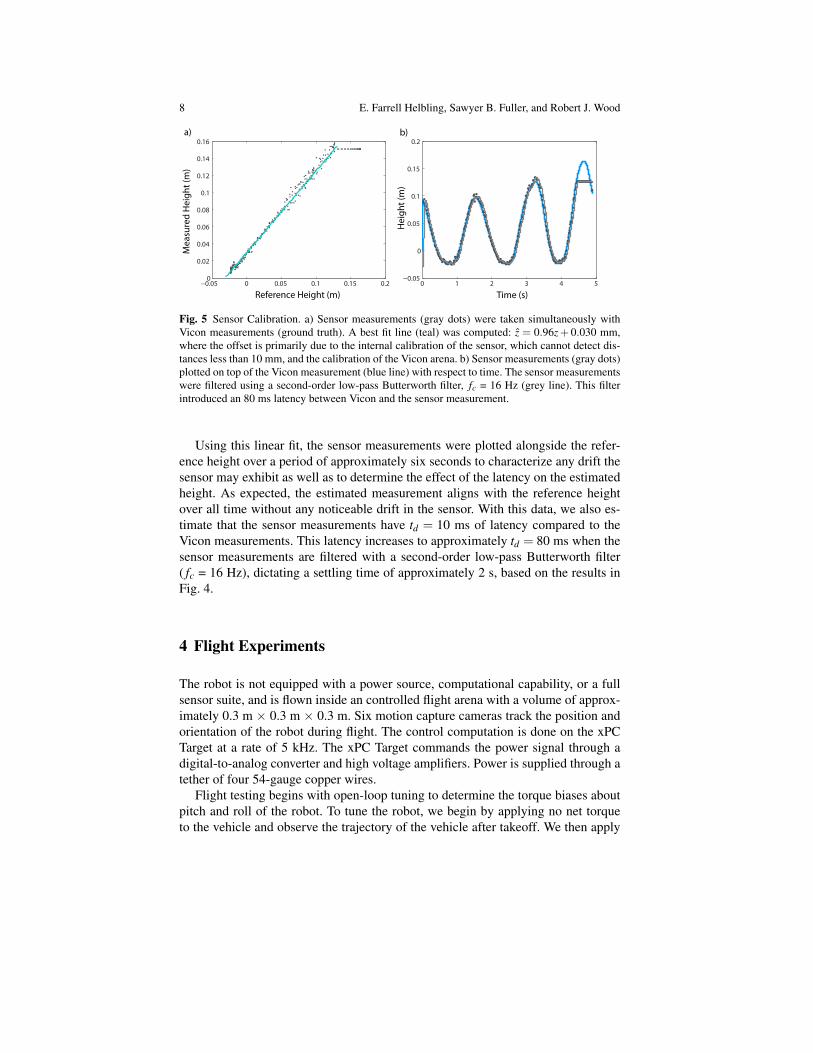
Fig. 5 Sensor Calibration. a) Sensor measurements (gray dots) were taken simultaneously withVicon measurements (ground truth). A best fit line (teal) was computed: z = 0.96z+ 0.030 mm,where the offset is primarily due to the internal calibration of the sensor, which cannot detect dis-tances less than 10 mm, and the calibration of the Vicon arena. b) Sensor measurements (gray dots)plotted on top of the Vicon measurement (blue line) with respect to time. The sensor measurementswere filtered using a second-order low-pass Butterworth filter, fc = 16 Hz (grey line). This filterintroduced an 80 ms latency between Vicon and the sensor measurement.
Using this linear fit, the sensor measurements were plotted alongside the refer-ence height over a period of approximately six seconds to characterize any drift thesensor may exhibit as well as to determine the effect of the latency on the estimatedheight. As expected, the estimated measurement aligns with the reference heightover all time without any noticeable drift in the sensor. With this data, we also es-timate that the sensor measurements have td = 10 ms of latency compared to theVicon measurements. This latency increases to approximately td = 80 ms when thesensor measurements are filtered with a second-order low-pass Butterworth filter( fc = 16 Hz), dictating a settling time of approximately 2 s, based on the results inFig. 4.
4 Flight Experiments
The robot is not equipped with a power source, computational capability, or a fullsensor suite, and is flown inside an controlled flight arena with a volume of approx-imately 0.3 m ⇥ 0.3 m ⇥ 0.3 m. Six motion capture cameras track the position andorientation of the robot during flight. The control computation is done on the xPCTarget at a rate of 5 kHz. The xPC Target commands the power signal through adigital-to-analog converter and high voltage amplifiers. Power is supplied through atether of four 54-gauge copper wires.
Flight testing begins with open-loop tuning to determine the torque biases aboutpitch and roll of the robot. To tune the robot, we begin by applying no net torqueto the vehicle and observe the trajectory of the vehicle after takeoff. We then apply

Altitude Control of an Insect-Scale MAV 9
trim values to oppose the observed torques. This process is repeated until the robot’stakeoff is vertically upright.
For all flights mentioned in this section, the robot is attached to a three-filamentkevlar thread and suspended above the surface to prevent wear on both the wings andwing hinges during crash landings. These filaments (approximately 30 cm in length)have negligible mass (0.2 mg) compared to that of the robot with the onboard sensor.In addition, we found that the filaments produce negligible torques on the robotduring flight. A 10 cm thread cannot support its own weight (20 µg) when extendedhorizontally, indicating that the bundle cannot exert more than 0.02 µNm of torqueon the robot – small compared to the 0.35 µNm of torque produced around the pitchand roll axes during hovering flight.
The altitude controller used during these flight experiments is described in de-tail in Sect. 2. The hovering flight experiments were done in multiple steps – firstthe vehicle was commanded to hover using Vicon estimates for altitude to tunethe controller gains and provide a baseline flight performance for our results. Alti-tude was then controlled with estimates from the onboard sensor – four flights werecommanded at an altitude of 8 cm to demonstrate repeatability and one flight at analtitude of 10 cm to test the range of the sensor. The attitude and lateral controllersused Vicon estimates of position and orientation for all flights. These are the firstdemonstrations of controlled altitude with onboard sensing in free flight.
4.1 Vicon Estimates
Once we determined the robot’s torque biases, we had to determine the controllergains in subsequent closed loop experiments. To first ensure that the robot had suf-ficient control authority to hover stably about a setpoint, Vicon was used to providethe estimated altitude measurement. The additional 27 mg at the base of the robotrequires larger thrust forces, and therefore larger flapping amplitudes, to lift off theground. The black line in Fig. 6 gives an example altitude trajectory of the vehi-cle during a hovering flight. The vehicle reaches and maintains the altitude setpointduring the 6 s flight (RMS error between the trajectory and the setpoint is 7 mm).
4.2 Sensor Estimates
Having determined that the loaded robot has the control authority to stably hoveraround a set point, the next step was to determine if the sensor feedback rate wassufficient to control altitude during free-flight. In these flight experiments, the fil-tered sensor measurements provided input to the altitude controller, while Viconestimates provided the lateral position and orientation of the robot to stabilize theattitude dynamics during flight. Fig. 6a provides an example of a hovering flightwith feedback from the ToF sensor. The robot takes off and reaches the setpoint in
10 E. Farrell Helbling, Sawyer B. Fuller, and Robert J. Wood
0.12
0.1
0.02
0.04
0.06
0.08
Time (s)
Hei
ght (
m)
a)
b)
0 1 2 3 4 5 6
0.12
0.1
0.02
0.04
0.06
0.08
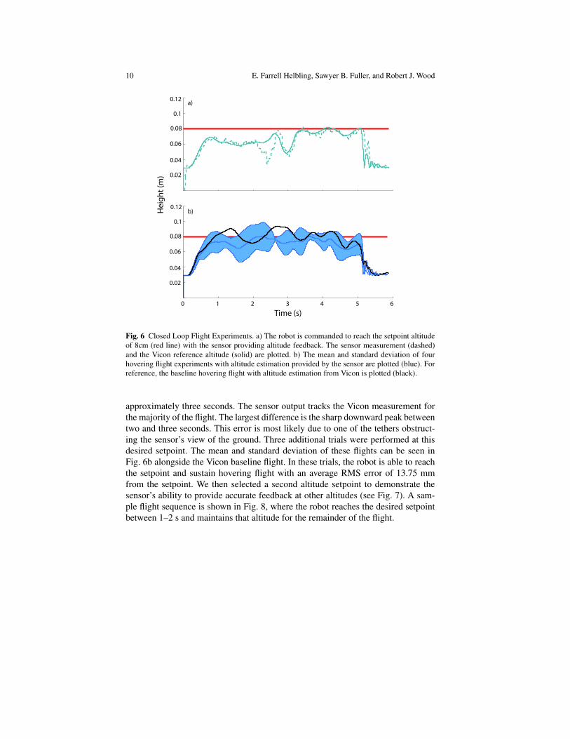
Fig. 6 Closed Loop Flight Experiments. a) The robot is commanded to reach the setpoint altitudeof 8cm (red line) with the sensor providing altitude feedback. The sensor measurement (dashed)and the Vicon reference altitude (solid) are plotted. b) The mean and standard deviation of fourhovering flight experiments with altitude estimation provided by the sensor are plotted (blue). Forreference, the baseline hovering flight with altitude estimation from Vicon is plotted (black).
approximately three seconds. The sensor output tracks the Vicon measurement forthe majority of the flight. The largest difference is the sharp downward peak betweentwo and three seconds. This error is most likely due to one of the tethers obstruct-ing the sensor’s view of the ground. Three additional trials were performed at thisdesired setpoint. The mean and standard deviation of these flights can be seen inFig. 6b alongside the Vicon baseline flight. In these trials, the robot is able to reachthe setpoint and sustain hovering flight with an average RMS error of 13.75 mmfrom the setpoint. We then selected a second altitude setpoint to demonstrate thesensor’s ability to provide accurate feedback at other altitudes (see Fig. 7). A sam-ple flight sequence is shown in Fig. 8, where the robot reaches the desired setpointbetween 1–2 s and maintains that altitude for the remainder of the flight.

Altitude Control of an Insect-Scale MAV 11
Fig. 7 Sensor Feedback forHovering Flight at 10 cmaltitude. The flight is plottedin time, with the setpointshown in red, sensor data(dashed line), and the Vicondata (solid line).
0.12
0.1
0.02
0.04
0.06
0.08
0 1 2 3 4 5 6
Time (s)
Hei
ght (
m)
Fig. 8 Sample Flight Sequence. The robot begins at the start altitude of approximately 3 cm, beginsflying to the desired altitude at 1 s, reaches the setpoint and maintains that altitude for the remainderof the flight, as demonstrated by the images at 3 s and 5 s.
4.3 Discussion
Closed loop flights with sensor estimates in the feedback loop controlled the alti-tude of the robot during hovering flight with altitude error of less than 1.5 cm, orwithin a half body length of the robot. These experiments also demonstrated thatcontrolled hovering with sensor estimates in the feedback loop had twice the RMSerror of the flights with Vicon feedback. To investigate this error, we verified thesensor measurements against the reference height from Vicon (see Fig. 9). The sen-sor performed as expected across all flights, with less than 5% of the measurementsdeviating from the linear trend. Outliers where the sensor measurement was lowerthan the expected value can be explained by an occluded view of the ground from thetether, and areas where the sensor measurement were higher are due to the attitudeof the vehicle moving away from the vertical axis. Practically, the robot does not tiltaway from the vertical axis more than 15�. At an altitude of approximately 10 cm,this second-order effect will cause deviations in sensor measurement of 4 mm largerthan the true value. In the future, accurate attitude estimation may not be availableand reliance on these estimates for correction may be impractical. However, giventhe limited number of outliers, this effect is negligible and the source of error is notsensor measurement.

12 E. Farrell Helbling, Sawyer B. Fuller, and Robert J. Wood
Fig. 9 Sensor CalibrationVerification. The sensor mea-surements for all flight exper-iments are plotted against theVicon ground truth estimate.The linear trend with unityslope held for all flights, withoutliers accounting for lessthan 5% of all measurements.
0 0.02 0.04 0.06 0.08 0.1 0.12 0.140
0.02
0.04
0.06
0.08
0.1
0.12
0.14
Reference Height (m)
Mea
sure
d H
eigh
t (m
)Previous studies [11] have shown that the power tether can produce large torques
on the robot during flight, making the vehicle more difficult to control during hover.The addition of a second power tether for sensor communication only increases thiseffect. Additional tuning will be necessary to compensate for these effects.
5 Conclusions
Altitude sensing is a necessary component for vision-based navigation. In thiswork, we determined a relationship between sensor latency and settling time forthe closed-loop altitude dynamics of this vehicle, elucidating the feedback require-ments for various altitude maneuvers. With this information, we selected a sensorthat met the mass, power, and latency constraints of the vehicle to perform altitudeestimation in free flight. The closed loop flights with sensor estimates in the feed-back loop are the first demonstrations of controlled altitude with onboard estimationfor an insect-scale robot in free flight. These flights, coupled with the results fromthe calibration experiments, demonstrate that the sensor is able to accurately mea-sure altitude, but further work is needed in tuning the controller gains to lower theaverage error about the desired setpoint.
The low mass of the sensor allows for additional payload, which can be used forcombinations of sensors. Future work into sensory fusion, including the integrationof an IMU to estimate attitude (as demonstrated in [10]) will enable the RoboBee toperform short hovering flights with only onboard sensory information. Additionally,autonomous visual navigation can be achieved with the integration of an onboardoptic flow sensor in combination with an attitude estimate from the IMU and anabsolute distance measure from the proximity sensor. These experiments will be thefirst demonstrations of sensor autonomy on an at-scale robotic insect. This work hasprovided an important step towards this goal.

Altitude Control of an Insect-Scale MAV 13
This work can also be applied to other MAVs, especially those with stringentpayload, power or computational requirements. Given the short range of this sensor,this sensor is impractical for altitude control over a large variation in height. How-ever, a ToF sensor could provide a precise measure of proximity and be combinedwith a pressure sensor to provide a coarse altitude estimate. We can envision thissensor being used for close range object detection or obstacle avoidance.
Acknowledgements The authors would like to thank Neel Doshi for his help in developing themodel for the closed loop dynamics. This material is based upon work supported by the NationalScience Foundation Graduate Research Fellowship under Grant No. (DGE1144152), and the WyssInstitute for Biologically Inspired Engineering. Any opinions, findings, and conclusions or recom-mendations expressed in this material are those of the authors and do not necessarily reflect theviews of the National Science Foundation.
References
1. Malcolm J. Abzug and Eugene E. Larrabee. Airplane stability and control, Second Edition: Ahistory of technologies that made aviation possible. Cambridge University Press, Cambridge,MA, 2002.
2. Karl Johan Astrom and Richard M. Murray. Feedback Systems: An Introduction for Scientistsand Engineers. Princeton University Press, 41 William Street, Princeton, NJ 08540, 2008.
3. Stanley S Baek, FL Garcia Bermudez, and Ronald S Fearing. Flight control for target seekingby 13 gram ornithopter. In Intelligent Robots and Systems (IROS), 2011 IEEE/RSJ Interna-tional Conference on, pages 2674–2681. IEEE, 2011.
4. Antoine Beyeler, Jean-Christophe Zufferey, and Dario Floreano. Vision-based control of near-obstacle flight. Autonomous Robots, 27:201–219, 2009. 10.1007/s10514-009-9139-6.
5. Pakpong Chirarattananon. Flight control of a millimeter-scale flapping-wing robot. 2014.6. Pakpong Chirarattananon, Kevin Y Ma, and Robert J Wood. Adaptive control of a millimeter-
scale flapping-wing robot. Bioinspiration & biomimetics, 9(2):025004, 2014.7. Christophe De Wagter, Sjoerd Tijmons, Bart DW Remes, and Guido CHE de Croon. Au-
tonomous flight of a 20-gram flapping wing mav with a 4-gram onboard stereo vision system.In Robotics and Automation (ICRA), 2014 IEEE International Conference on, pages 4982–4987. IEEE, 2014.
8. Robert Dudley. The biomechanics of insect flight: form, function, evolution. Princeton Uni-versity Press, 2002.
9. P.-E.J. Duhamel, N.O. Perez-Arancibia, G.L. Barrows, and R.J. Wood. Biologically in-spired optical-flow sensing for altitude control of flapping-wing microrobots. Mechatronics,IEEE/ASME Transactions on, 18(2):556–568, 2013.
10. Sawyer B Fuller, E Farrell Helbling, Pakpong Chirarattananon, and Robert J Wood. Usinga mems gyroscope to stabilize the attitude of a fly-sized hovering robot. In IMAV 2014:International Micro Air Vehicle Conference and Competition 2014, Delft, The Netherlands,August 12-15, 2014. Delft University of Technology, 2014.
11. Sawyer B. Fuller, Michael Karpelson, Andrea Censi, Kevin Y. Ma, and Robert J. Wood. Con-trolling free flight of a robotic fly using an onboard vision sensor inspired by insect ocelli.Journal of the Royal Society Interface, 2014. (in press).
12. E Farrell Helbling, Sawyer B Fuller, and Robert J Wood. Pitch and yaw control of a roboticinsect using an onboard magnetometer. In Robotics and Automation (ICRA), 2014 IEEE In-ternational Conference on, pages 5516–5522. IEEE, 2014.
13. James Sean Humbert. Bio-inspired visuomotor convergence in navigation and flight controlsystems. PhD thesis, California Institute of Technology, 2005.

14 E. Farrell Helbling, Sawyer B. Fuller, and Robert J. Wood
14. Intersil. Digital proximity sensor with interrupt function. Data Sheet, 2009.15. Vijay Kumar and Nathan Michael. Opportunities and challenges with autonomous micro aerial
vehicles. The International Journal of Robotics Research, 31(11):1279–1291, 2012.16. Kevin Y. Ma, Pakpong Chirarattananon, Sawyer B. Fuller, and Robert Wood. Controlled flight
of a biologically inspired, insect-scale robot. Science, May 2013.17. Kevin Y. Ma, Samuel M. Felton, and Robert J. Wood. Design, fabrication, and modeling of
the split actuator microrobotic bee. In Proceedings of the IEEE Int Robotics and AutomationConference, 2012.
18. ST Microelectronics. Vl6180x. proximity and ambient light sensing (als) module. Data Sheet,2014.
19. Murata. Ma40h1s-r. Product Specification of Ultrasonic Transducer, 2014.20. Measurement Specialties. Ms5607-02ba03. barometric pressure sensor, with stainless steel
cap. Data Sheet, 2012.21. Mandyam V Srinivasan. Honeybees as a model for the study of visually guided flight, navi-
gation, and biologically inspired robotics. Physiological Reviews, 91(2):413–460, 2011.