Embed Size (px)
Citation preview
Altralite™ Portable Low-Profile Floor Scale
Installation Manual
PN 202864 Rev AOctober 20, 2020

An ISO 9001 registered company© Rice Lake Weighing Systems. All rights reserved.
Rice Lake Weighing Systems® is a registered trademark of Rice Lake Weighing Systems.
All other brand or product names within this publication are trademarks or registered trademarks of their respective companies.
All information contained within this publication is, to the best of our knowledge, complete and accurate at the time of publication. Rice Lake Weighing Systems reserves the right to make
changes to the technology, features, specifications and design of the equipment without notice.
The most current version of this publication, software, firmware and all other product updates can be found on our website:
www.ricelake.com
Contents
© Rice Lake Weighing Systems ● All Rights Reserved i
Contents
Technical training seminars are available through Rice Lake Weighing Systems. Course descriptions and dates can be viewed at www.ricelake.com/trainingor obtained by calling 715-234-9171 and asking for the training department.
1.0 Introduction . . . . . . . . . . . . . . . . . . . . . . . . . . . . . . . . . . . . . . . . . . . . . . . . . . . . . . . . . . . . . . . . . . . . . . . . . . . . 11.1 Safety . . . . . . . . . . . . . . . . . . . . . . . . . . . . . . . . . . . . . . . . . . . . . . . . . . . . . . . . . . . . . . . . . . . . . . . . . . . . . . . . . . . . . . . . . . . . . 1
2.0 Installation . . . . . . . . . . . . . . . . . . . . . . . . . . . . . . . . . . . . . . . . . . . . . . . . . . . . . . . . . . . . . . . . . . . . . . . . . . . . . 22.1 Installation Overview . . . . . . . . . . . . . . . . . . . . . . . . . . . . . . . . . . . . . . . . . . . . . . . . . . . . . . . . . . . . . . . . . . . . . . . . . . . . . . . . . . 22.2 Site Preparation . . . . . . . . . . . . . . . . . . . . . . . . . . . . . . . . . . . . . . . . . . . . . . . . . . . . . . . . . . . . . . . . . . . . . . . . . . . . . . . . . . . . . 22.3 Unpacking . . . . . . . . . . . . . . . . . . . . . . . . . . . . . . . . . . . . . . . . . . . . . . . . . . . . . . . . . . . . . . . . . . . . . . . . . . . . . . . . . . . . . . . . . . 22.4 Assembly. . . . . . . . . . . . . . . . . . . . . . . . . . . . . . . . . . . . . . . . . . . . . . . . . . . . . . . . . . . . . . . . . . . . . . . . . . . . . . . . . . . . . . . . . . . 3
2.4.1 Installing and Adjusting Feet . . . . . . . . . . . . . . . . . . . . . . . . . . . . . . . . . . . . . . . . . . . . . . . . . . . . . . . . . . . . . . . . . . . . 32.4.2 Mounting Plate Installation . . . . . . . . . . . . . . . . . . . . . . . . . . . . . . . . . . . . . . . . . . . . . . . . . . . . . . . . . . . . . . . . . . . . . . 3
2.5 Junction Box Connections. . . . . . . . . . . . . . . . . . . . . . . . . . . . . . . . . . . . . . . . . . . . . . . . . . . . . . . . . . . . . . . . . . . . . . . . . . . . . . 42.5.1 Electrical Interface to Indicator . . . . . . . . . . . . . . . . . . . . . . . . . . . . . . . . . . . . . . . . . . . . . . . . . . . . . . . . . . . . . . . . . . . 4
2.6 Pit Installation . . . . . . . . . . . . . . . . . . . . . . . . . . . . . . . . . . . . . . . . . . . . . . . . . . . . . . . . . . . . . . . . . . . . . . . . . . . . . . . . . . . . . . . 52.7 Access Ramps . . . . . . . . . . . . . . . . . . . . . . . . . . . . . . . . . . . . . . . . . . . . . . . . . . . . . . . . . . . . . . . . . . . . . . . . . . . . . . . . . . . . . . 6
3.0 Calibration . . . . . . . . . . . . . . . . . . . . . . . . . . . . . . . . . . . . . . . . . . . . . . . . . . . . . . . . . . . . . . . . . . . . . . . . . . . . . 73.1 Mechanical Adjustments . . . . . . . . . . . . . . . . . . . . . . . . . . . . . . . . . . . . . . . . . . . . . . . . . . . . . . . . . . . . . . . . . . . . . . . . . . . . . . . 73.2 Corner Correction . . . . . . . . . . . . . . . . . . . . . . . . . . . . . . . . . . . . . . . . . . . . . . . . . . . . . . . . . . . . . . . . . . . . . . . . . . . . . . . . . . . . 73.3 Calibration Procedure . . . . . . . . . . . . . . . . . . . . . . . . . . . . . . . . . . . . . . . . . . . . . . . . . . . . . . . . . . . . . . . . . . . . . . . . . . . . . . . . . 8
4.0 Troubleshooting . . . . . . . . . . . . . . . . . . . . . . . . . . . . . . . . . . . . . . . . . . . . . . . . . . . . . . . . . . . . . . . . . . . . . . . . 94.1 Troubleshooting Guide . . . . . . . . . . . . . . . . . . . . . . . . . . . . . . . . . . . . . . . . . . . . . . . . . . . . . . . . . . . . . . . . . . . . . . . . . . . . . . . . 94.2 Periodic Maintenance . . . . . . . . . . . . . . . . . . . . . . . . . . . . . . . . . . . . . . . . . . . . . . . . . . . . . . . . . . . . . . . . . . . . . . . . . . . . . . . . . 94.3 Load Cell Replacement . . . . . . . . . . . . . . . . . . . . . . . . . . . . . . . . . . . . . . . . . . . . . . . . . . . . . . . . . . . . . . . . . . . . . . . . . . . . . . . 10
4.3.1 Load Cell Wiring to Junction Box . . . . . . . . . . . . . . . . . . . . . . . . . . . . . . . . . . . . . . . . . . . . . . . . . . . . . . . . . . . . . . . . 12
5.0 Limited Warranty . . . . . . . . . . . . . . . . . . . . . . . . . . . . . . . . . . . . . . . . . . . . . . . . . . . . . . . . . . . . . . . . . . . . . . . 136.0 Specifications . . . . . . . . . . . . . . . . . . . . . . . . . . . . . . . . . . . . . . . . . . . . . . . . . . . . . . . . . . . . . . . . . . . . . . . . . 14
Altralite Portable Low-Profile Floor Scale
ii Visit our website www.RiceLake.com
Rice Lake continually offers web-based video training on a growing selection of product-related topics at no cost. Visit www.ricelake.com/webinars
Introduction
© Rice Lake Weighing Systems ● All Rights Reserved 1
1.0 IntroductionThe Altralite Floor Scale is a fully electronic, low profile load receiver. The Altralite Floor Scale is available in 4' x 4' (1.22 m x 1.22 m) with the capacity of 5K (2267.96 kg). The Altralite Floor Scale uses four corner-mounted, FM-approved load cells, with the cells recessed into the frame channels for protection. A signal-trim summing board enclosed in a stainless steel, NEMA Type 4X junction box is included for corner corrections.
All models come pre-trimmed. Corner corrections should not be necessary.
Load cell cables are enclosed in conduit through the main channels, and held down with replaceable cable ties near each corner, eliminating the possibility of cable damage in portable applications. Also useful for portable applications are threaded corner holes in the deck for removable eye bolts to allow lifting the scale from above with chains.
The possibility of foot and load cell damage from forklift tines, the scale should always be lifted from above with chains through the eye bolts.
The adjustable feet are used to allow leveling the scale to make up for minor floor irregularities. For permanent installations, two of the four feet can be held in place on the floor with optional floor mounting plates to guard against deck movement.Other available options include custom frames for pit installations, and access ramps for all sizes and models of the Altralite Floor Scale. Decks designed for use in pits can be ordered with holes drilled in the deck directly above each foot for adjusting foot height with a screwdriver from above.
Manuals and additional resources are available from the Rice Lake Weighing Systems website at www.ricelake.comWarranty information can be found on the website at www.ricelake.com/warranties
1.1 SafetySafety Signal Definitions:
Indicates an imminently hazardous situation that, if not avoided, will result in death or serious injury. Includes hazards that are exposed when guards are removed.Indicates a potentially hazardous situation that, if not avoided, could result in serious injury or death. Includes hazards that are exposed when guards are removed.
Indicates a potentially hazardous situation that, if not avoided, could result in minor or moderate injury.
Indicates information about procedures that, if not observed, could result in damage to equipment or corruption to and loss of data.
General SafetyDo not operate or work on this equipment unless this manual has been read and all instructions are understood. Failure to follow the instructions or heed the warnings could result in injury or death. Contact any Rice Lake Weighing Systems dealer for replacement manuals.
Failure to heed could result in serious injury or death.Do not allow minors (children) or inexperienced persons to operate this unit.Do not operate without all shields and guards in place.Do not jump on the scale.Do not use for purposes other then weight taking.Do not place fingers into slots or possible pinch points.Do not use any load bearing component that is worn beyond 5% of the original dimension.Do not use this product if any of the components are cracked.Do not exceed the rated load limit of the unit.Do not make alterations or modifications to the unit.Do not remove or obscure warning labels.Do not use near water.Before opening the unit, ensure the power cord is disconnected from the outlet.Keep hands, feet and loose clothing away from moving parts.
Note
WARNING
DANGER
WARNING
CAUTION
IMPORTANT
WARNING
Altralite Portable Low-Profile Floor Scale
2 Visit our website www.RiceLake.com
2.0 InstallationThis section provides information regarding the installation of the Altralite Floor Scale.
2.1 Installation OverviewStandard installation of the Altralite Floor Scale consists of the following steps:
1. Select a site.2. Check levelness and smoothness of site.3. Unpack scale.4. Adjust the four feet on the scale.5. Install mounting plates to the floor.6. Connect cable to junction box and indicator.7. Calibrate the unit.
Pit installations and access ramps are described in Section 2.6 on page 5 and Section 2.7 on page 6.Consult factory for additional pit and access ramp information at www.ricelake.com.
2.2 Site PreparationThe scale must not be loaded beyond its capacity.
Do not select a site where overweight loads would have to maneuver to avoid crossing the platform.Avoid areas where the scale might receive damaging side impacts from wheels or forklift tines, or shock damage from falling objects. Avoid areas where water may damage a scale not meant for a washdown environment.
The interface cable between the scale and the indicator must be protected against crushing, cutting, or moisture damage. If the chosen site has potential dangers, some method of protection, such as running the cable in conduit, will be necessary.In operation, the scale must be level within 1/4''. Either choose a site where the floor is close to this standard to avoid excessive shimming, or modify the floor at the chosen site to meet this standard.
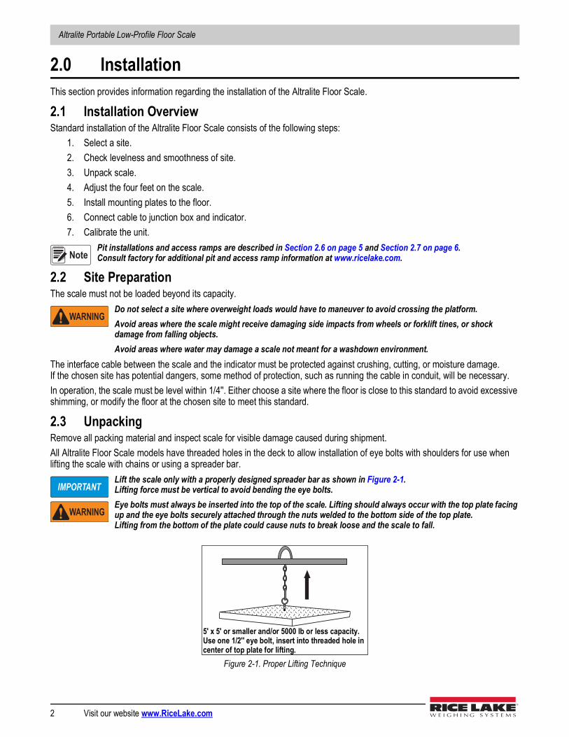
2.3 UnpackingRemove all packing material and inspect scale for visible damage caused during shipment.All Altralite Floor Scale models have threaded holes in the deck to allow installation of eye bolts with shoulders for use when lifting the scale with chains or using a spreader bar.
Lift the scale only with a properly designed spreader bar as shown in Figure 2-1. Lifting force must be vertical to avoid bending the eye bolts.Eye bolts must always be inserted into the top of the scale. Lifting should always occur with the top plate facing up and the eye bolts securely attached through the nuts welded to the bottom side of the top plate. Lifting from the bottom of the plate could cause nuts to break loose and the scale to fall.
Figure 2-1. Proper Lifting Technique
Note
WARNING
IMPORTANT
WARNING
5' x 5' or smaller and/or 5000 lb or less capacity.Use one 1/2'' eye bolt, insert into threaded hole in center of top plate for lifting.

Installation
© Rice Lake Weighing Systems ● All Rights Reserved 3
2.4 AssemblyThe following paragraphs present instructions for installing and adjusting the scale feet and mounting plate installation.2.4.1 Installing and Adjusting FeetFor load cell protection during shipping, the scale feet are shipped detached from the load cells. The feet are secured to the bottom of the shipping pallet along with the load cell cable, strain relief fitting and product literature.
1. Remove all parts from the envelope.2. Screw one foot into each load cell and turn until the foot touches either the load cell or the underside of the deck.3. Unscrew each foot with three complete turns.4. Place a spirit level on the deck.
Adjust any high corners not in contact with the floor by further unscrewing the feet on those corners until they just contact the floor surface.
5. When all feet are in contact with the floor, check the deck with the spirit level to be sure the scale is within 1/4'' of level.2.4.2 Mounting Plate InstallationFor permanent applications, the scale should be secured to the floor to prevent sideways movement. Two mounting plates, with holes that slightly exceed the foot diameter, are available as an option for that purpose.
1. Lift the scale so that the feet are approximately 1'' off the floor.2. Slide mounting plates under two diagonally opposed feet.3. Lower the scale back to the floor, and position the plates as shown in Figure 2-2 so that the bolt down holes are
accessible from above.4. Using the mounting plates as templates, drill pilot holes into the floor for suitable anchor bolts.5. Bolt the plates to the floor using 1/2'' anchor bolts.6. Recheck foot adjustment and deck level after this operation.
For installations using access ramps, mounting plates are not necessary as the ramps have built-in mounting plates to secure the scale feet.
Figure 2-2. Mounting Plate Installation
Note
Note
4.50"
.812" DIA
MOUNTING PLATE
SCALE DECK
FOOT
Altralite Portable Low-Profile Floor Scale
4 Visit our website www.RiceLake.com
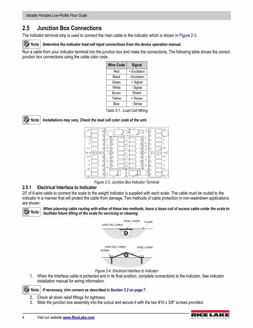
2.5 Junction Box ConnectionsThe indicator terminal strip is used to connect the main cable to the indicator which is shown in Figure 2-3.
Determine the indicator load cell input connections from the device operation manual.
Run a cable from your indicator terminal into the junction box and make the connections. The following table shows the correct junction box connections using the cable color code.
Installations may vary. Check the load cell color code of the unit.
Figure 2-3. Junction Box Indicator Terminal2.5.1 Electrical Interface to Indicator20' of 6-wire cable to connect the scale to the weight indicator is supplied with each scale. The cable must be routed to the indicator in a manner that will protect the cable from damage. Two methods of cable protection in non-washdown applications are shown.
When planning cable routing with either of these two methods, leave a loose coil of excess cable under the scale to facilitate future lifting of the scale for servicing or cleaning.
Figure 2-4. Electrical Interface to Indicator1. When the interface cable is protected and in its final position, complete connections to the indicator. See indicator
installation manual for wiring information.
If necessary, trim corners as described in Section 3.2 on page 7.
2. Check all strain relief fittings for tightness.3. Slide the junction box assembly into the cutout and secure it with the two #10 x 3/8'' screws provided.
Wire Code SignalRed + Excitation
Black - ExcitationGreen + SignalWhite - SignalBrown ShieldYellow + SenseBlue - Sense
Table 2-1. Load Cell Wiring
Note
Note
JP4
JP 2
PT4 PT3JP3
PT1
EXP
PT2JP1
1
CELL
4
1
CELL1
1
CELL
3
1
CELL2
IND
-EX
-SI
SHD
+SI
+EX
M
R
N
I
-SI
S2C
I
A
G
+EX
+SI
-SI
SHD
-EX
I
S
G
AL
T+SI
M
SI
N
L
TR
+EX
-EX
-SI
SHD
+SI
+EX
+SI
-EX
-SI
SHD
-EX
SHD
+SE
-SE
+EX
Note
LOAD CELL CABLE STEEL COVER
FLOOR
SCREW
LOAD CELL CABLE
STEEL COVER
Note

Installation
© Rice Lake Weighing Systems ● All Rights Reserved 5
2.6 Pit Installation Consult factory for additional pit information at www.ricelake.com.
The Altralite Floor Scale can be installed in a shallow pit using the optional Altralite Floor Scale pit frame.Optional height-adjustment holes are available. The following site considerations and pit frame drawings are meant only as a brief overview of the principles involved with mounting the scale in a floor-level pit.
The pit must be installed in a suitable poured-concrete foundation according to standard construction practices.
Figure 2-5. Cover Plate
Figure 2-6. Section Showing Installed Altralite Floor Scale and Pit Frame
Site ConsiderationsDebris, floor sweepings, or material spills may accumulate in the pit and interfere with scale operation. Periodically clean the pit.
The Altralite Floor Scale has threaded holes for eye bolts so the scale can be easily lifted from the pit.Plan the pit location out of main traffic areas to prevent such accidental damaging overloads.
Weight overloads, even momentary such as driving a loaded forklift over a scale corner, will damage load cells.
A 1:24 slope is recommended for the pit, with full grouting under the corner pads as shown in Figure 2-4 on page 4.
Corner pads must be fully grouted.
Note
Note
COVER PLATE
1:24 SLOPE
LOAD CELL
CUPFOOT ASSEMBLY
GROUT
IMPORTANT
WARNING
Note
Altralite Portable Low-Profile Floor Scale
6 Visit our website www.RiceLake.com
2.7 Access Ramps Consult factory for additional access ramp information at www.ricelake.com.
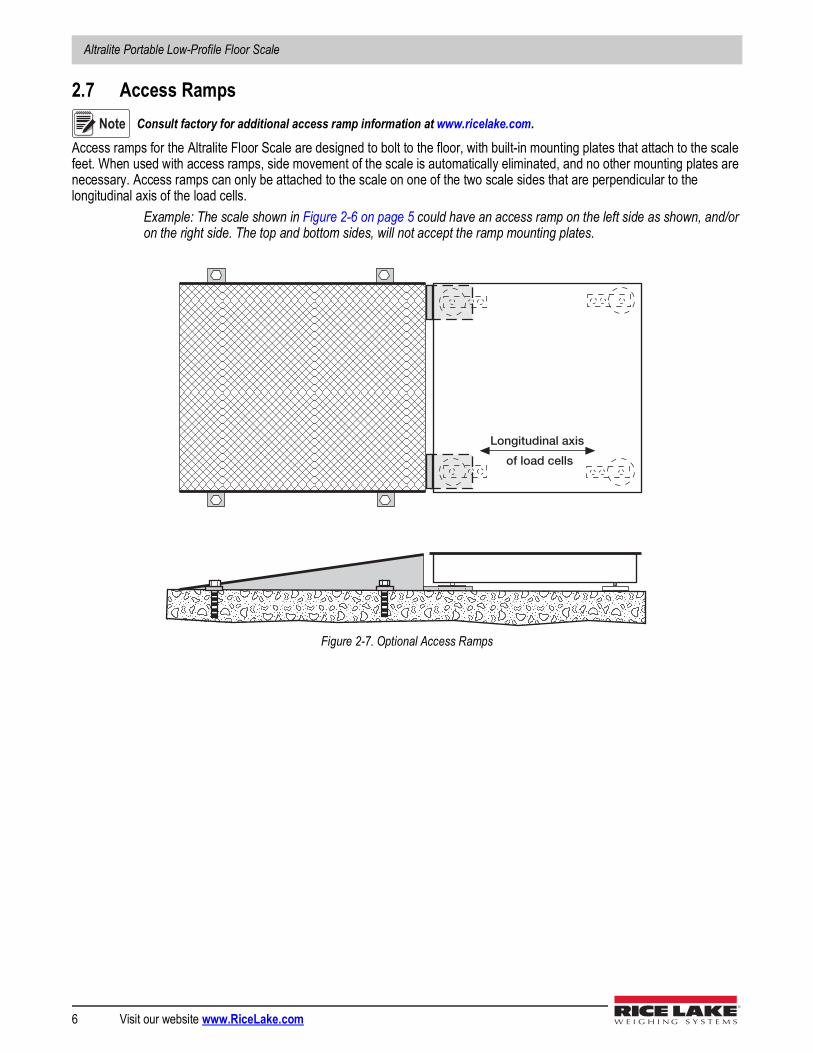
Access ramps for the Altralite Floor Scale are designed to bolt to the floor, with built-in mounting plates that attach to the scale feet. When used with access ramps, side movement of the scale is automatically eliminated, and no other mounting plates are necessary. Access ramps can only be attached to the scale on one of the two scale sides that are perpendicular to the longitudinal axis of the load cells.
Example: The scale shown in Figure 2-6 on page 5 could have an access ramp on the left side as shown, and/or on the right side. The top and bottom sides, will not accept the ramp mounting plates.
Figure 2-7. Optional Access Ramps
Note
Longitudinal axis
of load cells
Calibration
© Rice Lake Weighing Systems ● All Rights Reserved 7
3.0 CalibrationThis section provides information regarding calibration of the Altralite Floor Scale.
3.1 Mechanical AdjustmentsTo accommodate minor floor unevenness, scale feet can be used to adjust scale height up or down a fraction of an inch. Adjust the feet by hand (lift the scale corner slightly with a pry bar) until all feet are contacting the floor equally. No jam nuts are supplied for locking the feet, as there is a slight decrease in accuracy when jam nuts are tightened. If the application requires the feet to be secured, use Teflon tape or Loctite.
When adjusting scale feet, use care to prevent scale foot from bottoming out against the underside of the load cell. Also, the foot stem may be damaged by bending or stripping threads if extended beyond the maximum height adjustment.
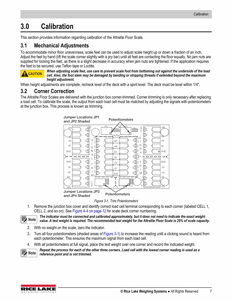
When height adjustments are complete, recheck level of the deck with a spirit level. The deck must be level within 1/4".3.2 Corner CorrectionThe Altralite Floor Scales are delivered with the junction box corner-trimmed. Corner trimming is only necessary after replacing a load cell. To calibrate the scale, the output from each load cell must be matched by adjusting the signals with potentiometers at the junction box. This process is known as trimming.
Figure 3-1. Trim Potentiometers1. Remove the junction box cover and identify correct load cell terminal corresponding to each corner (labeled CELL 1,
CELL 2, and so on). See Figure 4-4 on page 12 for scale deck corner numbering.The indicator must be connected and calibrated approximately, but it does not need to indicate the exact weight value. A test weight is required. The recommended test weight for the Altralite Floor Scale is 25% of scale capacity.
2. With no weight on the scale, zero the indicator.3. Turn all four potentiometers (shaded areas of Figure 3-1) to increase the reading until a clicking sound is heard from
each potentiometer. This ensures the maximum signal from each load cell.4. With all potentiometers at full signal, place the test weight over one corner and record the indicated weight.
Repeat the process for each of the other three corners. Load cell with the lowest corner reading is used as a reference point and is not trimmed.
CAUTION
JP4
JP2
PT4 PT3 JP3
PT1
EXP
PT2JP1
1
CELL
4
1
CELL1
1
CELL
3
1
CELL2
IND
-EX
-SI
SHD
+SI
+EX
M
R
N
I
-SI
S2C
I
A
G
+EX
+SI
-SI
SHD
-EX
I
S
G
AL
T+SI
M
SI
N
L
TR
+EX
-EX
-SI
SHD
+SI
+EX
+SI
-EX
-SI
SHD
-EX
SHD
+SE
-SE
+EX
PotentiometersJumper Locations JP3 and JP4 Shaded
Jumper Locations JP1 and JP2 Shaded Potentiometers
Note
Note
Altralite Portable Low-Profile Floor Scale
8 Visit our website www.RiceLake.com
5. Place the test weight over one of the other three corners and use that cell’s potentiometer to adjust the cell output down to the reference cell output.
Repeat this procedure with the other two high corners.
6. Adjustments are somewhat interactive, and adjusting the three higher outputs may affect the reference cell output, especially in smaller scale decks.
7. Rezero the indicator and repeat the test until all corners read within ±.1% of the test weight used.3.3 Calibration ProcedureRefer to the indicator manual to determine correct calibration procedures.
It is recommended that the scale be exercised before calibration to be certain that everything is seated. Load the scale to near capacity two or three times.
1. With no load on the scale, place the indicator in its calibration mode and perform a zero calibration.2. Place test weights on the platform equal to 70% – 80% of the scale’s capacity.
If several weights are used, they should be evenly distributed around the platform. Perform a span calibration.
3. Remove the test weights and check the zero reading.4. Repeat the calibration process if necessary.
Note
Note
Note

Troubleshooting
© Rice Lake Weighing Systems ● All Rights Reserved 9
4.0 TroubleshootingThis section provides information regarding the troubleshooting of the Altralite Floor Scale.
4.1 Troubleshooting Guide
4.2 Periodic MaintenanceThe space between the platform side and pit frame, and the surface beneath the platform must be periodically cleaned to prevent debris build up. More frequent cleaning of these areas is necessary with scales mounted in pits.
Do not attempt to use scales with load cells that are not hermetically sealed in washdown applications. Water damage is a common cause of failure in non-hermetically-sealed load cells. Use care with high pressure steam wash downs for hermetically-sealed load cells. The steam may not damage the load cells, but the elevated temperatures may cause incorrect readings until the unit cools to room temperature.
Issue Possible Cause SolutionSystem does not operate - no display Power disconnected Check and reconnect
Indicator fuse blown Replace fusel; Check for causeInterface cable cut or disconnected RepairSignal leads incorrectly installed at indicator Install according to indicator installation manual
Display stays at zero Indicator faulty Service indicatorLoad cell connections faulty Check cable connections in junction box and at indicator
Erratic weights Vibration near scale Remove source of vibration or move scalePlatform not level to within 1/4'' Level scale by adjusting feet or shimming if necessaryLoad cell or cable water damage ReplaceDebris under load cells or platform CleanIndicator faulty Use simulator to test indicator for stability;
Service indicatorConsistently high or low weights Indicator not properly adjusted to zero Zero the indicator according to indicator manual
Platform binding Obtain adequate clearance for free platform movementIndicator not calibrated Calibrate according to indicator manual and Section 3.3
on page 8Load cells are faulty Test and replace load cells if necessaryFeet touching deck underside Adjust feet downward to provide clearance
Table 4-1. Troubleshooting
CAUTION
Altralite Portable Low-Profile Floor Scale
10 Visit our website www.RiceLake.com
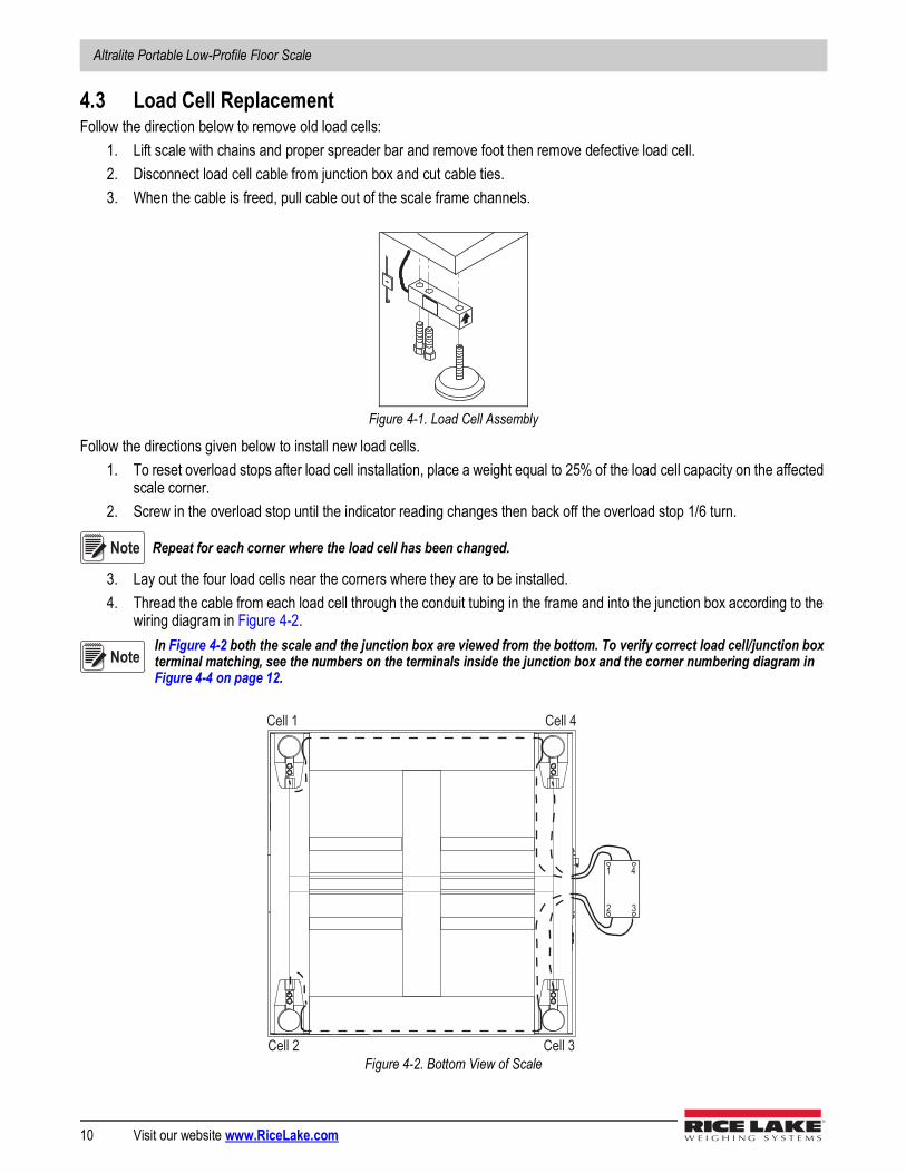
4.3 Load Cell ReplacementFollow the direction below to remove old load cells:
1. Lift scale with chains and proper spreader bar and remove foot then remove defective load cell.2. Disconnect load cell cable from junction box and cut cable ties.3. When the cable is freed, pull cable out of the scale frame channels.
Figure 4-1. Load Cell Assembly
Follow the directions given below to install new load cells.1. To reset overload stops after load cell installation, place a weight equal to 25% of the load cell capacity on the affected
scale corner.2. Screw in the overload stop until the indicator reading changes then back off the overload stop 1/6 turn.
Repeat for each corner where the load cell has been changed.
3. Lay out the four load cells near the corners where they are to be installed.4. Thread the cable from each load cell through the conduit tubing in the frame and into the junction box according to the
wiring diagram in Figure 4-2.In Figure 4-2 both the scale and the junction box are viewed from the bottom. To verify correct load cell/junction box terminal matching, see the numbers on the terminals inside the junction box and the corner numbering diagram in Figure 4-4 on page 12.
Figure 4-2. Bottom View of Scale
Note
Note
Cell 3Cell 2
Cell 4Cell 1
3
4
2
1
Troubleshooting
© Rice Lake Weighing Systems ● All Rights Reserved 11
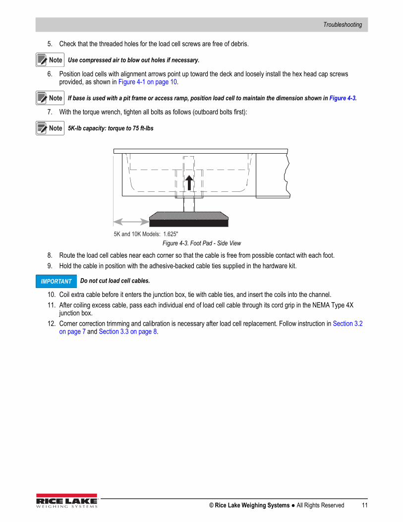
5. Check that the threaded holes for the load cell screws are free of debris.
Use compressed air to blow out holes if necessary.
6. Position load cells with alignment arrows point up toward the deck and loosely install the hex head cap screws provided, as shown in Figure 4-1 on page 10.
If base is used with a pit frame or access ramp, position load cell to maintain the dimension shown in Figure 4-3.
7. With the torque wrench, tighten all bolts as follows (outboard bolts first):
5K-lb capacity: torque to 75 ft-lbs
Figure 4-3. Foot Pad - Side View
8. Route the load cell cables near each corner so that the cable is free from possible contact with each foot.9. Hold the cable in position with the adhesive-backed cable ties supplied in the hardware kit.
Do not cut load cell cables.
10. Coil extra cable before it enters the junction box, tie with cable ties, and insert the coils into the channel.11. After coiling excess cable, pass each individual end of load cell cable through its cord grip in the NEMA Type 4X
junction box.12. Corner correction trimming and calibration is necessary after load cell replacement. Follow instruction in Section 3.2
on page 7 and Section 3.3 on page 8.
Note
Note
Note
5K and 10K Models: 1.625"
IMPORTANT
Altralite Portable Low-Profile Floor Scale
12 Visit our website www.RiceLake.com
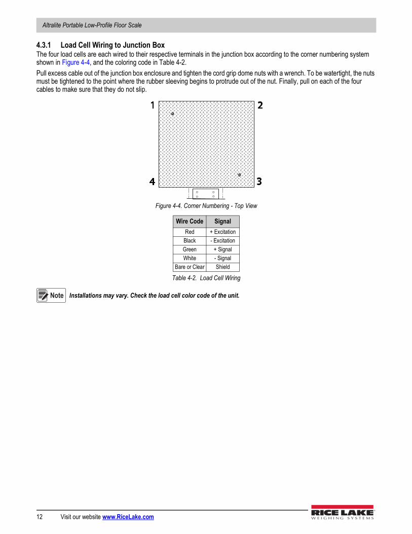
4.3.1 Load Cell Wiring to Junction BoxThe four load cells are each wired to their respective terminals in the junction box according to the corner numbering system shown in Figure 4-4, and the coloring code in Table 4-2.Pull excess cable out of the junction box enclosure and tighten the cord grip dome nuts with a wrench. To be watertight, the nuts must be tightened to the point where the rubber sleeving begins to protrude out of the nut. Finally, pull on each of the four cables to make sure that they do not slip.
Figure 4-4. Corner Numbering - Top View
Installations may vary. Check the load cell color code of the unit.
Wire Code SignalRed + Excitation
Black - ExcitationGreen + SignalWhite - Signal
Bare or Clear Shield
Table 4-2. Load Cell Wiring
1
4
2
3
Note
Limited Warranty
© Rice Lake Weighing Systems ● All Rights Reserved 13
5.0 Limited WarrantyRice Lake Weighing Systems (RLWS) warrants that all RLWS equipment and systems properly installed by a Distributor or Original Equipment Manufacturer (OEM) will operate per written specifications as confirmed by the Distributor/OEM and accepted by RLWS. Altralite fabricated platforms and weldments are warranted against defects in materials and workmanship for five years. Load cells are warranted for two year and all other components are warranted for one year.RLWS warrants that the equipment sold hereunder will conform to the current written specifications authorized by RLWS. RLWS warrants the equipment against faulty workmanship and defective materials. If any equipment fails to conform to these warranties, RLWS will, at its option, repair or replace such goods returned within the warranty period subject to the following conditions:
• Upon discovery by Buyer of such nonconformity, RLWS will be given prompt written notice with a detailed explanation of the alleged deficiencies.
• Individual electronic components returned to RLWS for warranty purposes must be packaged to prevent electrostatic discharge (ESD) damage in shipment. Packaging requirements are listed in a publication, “Protecting Your Components From Static Damage in Shipment,” available from RLWS Equipment Return Department.
• Examination of such equipment by RLWS confirms that the nonconformity actually exists, and was not caused by accident, misuse, neglect, alteration, improper installation, improper repair or improper testing; RLWS shall be the sole judge of all alleged non-conformities.
• Such equipment has not been modified, altered, or changed by any person other than RLWS or its duly authorized repair agents.
• RLWS will have a reasonable time to repair or replace the defective equipment. Buyer is responsible for shipping charges both ways.
• In no event will RLWS be responsible for travel time or on-location repairs, including assembly or disassembly of equipment, nor will RLWS be liable for the cost of any repairs made by others.
These warranties exclude all other warranties, expressed or implied, including without limitation warranties of merchantability or fitness for a particular purpose. Neither RLWS nor distributor will, in any event, be liable for incidental or consequential damages.RLWS and buyer agree that RLWS’ sole and exclusive liability hereunder is limited to repair or replacement of such goods.In accepting this warranty, the buyer waives any and all other claims to warranty.Should the seller be other than RLWS, the buyer agrees to look only to the seller for warranty claims.No terms, conditions, understanding, or agreements purporting to modify the terms of this warranty shall have any legal effect unless made in writing and signed by a corporate officer of RLWS and the Buyer.
Altralite Portable Low-Profile Floor Scale
14 Visit our website www.RiceLake.com
6.0 SpecificationsEnd Load Capacity100% full scale at 5000 lbs
Cable Length20' (6.1m) for connecting junction box to indicator
WarrantyAltralite Weldment: 5-yearsLoad Cell: 2-yearsOther Components: 1-year
Certifications and Approvals


230 W. Coleman St. • Rice Lake, WI 54868 • USAU.S. 800-472-6703 • Canada/Mexico 800-321-6703 • International 715-234-9171 • Europe +31 (0)26 472 1319
Rice Lake Weighing Systems is an ISO 9001 registered company. © Rice Lake Weighing Systems Specifications subject to change without notice.
www.ricelake.com PN 202864 Rev AOctober 20, 2020