Embed Size (px)
Citation preview
ALTRONIC GAS ENGINE GOVERNOR OPERATING MANUAL GOV10, GOV50 FORM GOV OM 10-02 WARNING: DEVIATION FROM THESE INSTALLATION INSTRUCTIONS MAY LEAD TO IMPROPER ENGINE OPERATION WHICH COULD CAUSE PERSONAL INJURY TO OPERATORS OR OTHER NEARBY PERSONNEL.
Version 5.02 November, 2002
ALTRONIC, INC. 712 Trumbull Ave.
Girard, Ohio 44420 USA
© Altronic, Inc. 2002
Form GOV OM 11-02.
1-1
Section 1
INTRODUCTION
Form GOV OM 11-02.
1-2
This manual provides instruction and maintenance information for the
GOV10/50. It is recommended that the user read this manual in its
entirety before commencing operations.
Do NOT attempt to operate, maintain, or repair the fuel control valve until
the contents of this document have been read and are thoroughly
understood.
Every attempt has been made to provide sufficient information in this
manual for the proper operation and maintenance of the GOV10/50.
If additional information is required, please contact:
Altronic, Inc. 712 Trumbull Ave. Girard, OH 44420 (330) 545-9768
INTRODUCTION
Form GOV OM 11-02.
1-3
The Altronic Gas Engine Governors are normally used with natural gas.
Natural gas and air, when combined together, become very combustible
and when contained within an enclosure, such as a fuel-injected
reciprocating engine or its exhaust system can explode in a violent
manner when ignited. It is necessary to always use extreme caution
when working with any fuel system. The control systems used with
natural gas fired, reciprocating engines should always be designed to be
“fail-safe”. Towards this goal, the GOV10/50 Gas Engine Governor plays
an important part in the safety of the whole system.
The GOV10/50 Gas Engine Governor is NOT a shutoff valve. Shutoff
valves should be used in addition to the Gas Engine Governor. The fuel
system should be designed in such a way that:
1. No single failure of a component will cause the fuel system to
admit fuel to the engine when the engine has been shutdown. 2. No single failure can result in grossly over-fueling the engine
when attempting to start. Failure to follow the above rules may lead to possibly serious damage to
equipment or to personnel.
WARNING

Form GOV OM 11-02
2-1
Section 2 THEORY OF OPERATION
Form GOV OM 11-02
2-2
The GOV10/50 Gas Engine Governor is a gas engine governor designed
to be used as the speed control on fuel-injected reciprocating natural gas
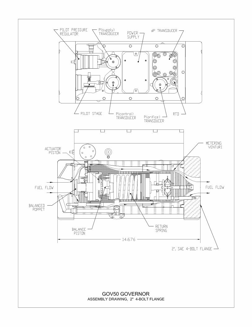
engines. The valve controls fuel flow by varying an orifice and uses fuel
gas pressure for actuation muscle. The valve consists of a tubular main
body, a poppet assembly, and an electronics component housing.
These three main sub-assemblies form a single integrated unit. The
GOV requires no separate actuators or mechanical linkage.
The main body contains an orifice plate (used for the optional flow
measurement feature) and the poppet assembly. Mounting flanges are
also bolted to the main body. The poppet assembly consists of the
following
• Poppet
• Poppet seat
• Oil-filled bellows section for dampening
• Return spring
The electronics housing contains
• Control gas pressure regulator
• Muscle gas controlling components
• Three (3) pressure transducers
• ∆P transducer
• Fuel temperature RTD
• 16-bit microprocessor board
The Governor Control Display Terminal accomplishes all necessary input
programming and data value read outs. The control module design
allows remote mounting at the operating or shutdown panel board of the
engine. RS-485 serial communications will allow up to 350 foot distance
for the remote terminal location.
Engine speed set point may be changed from the Display Terminal (part
no. TSA-100) or via a 4 to 20 mA signal input.
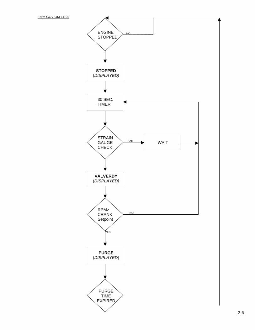
The GOV remains closed when the engine is not running. While in this
stopped mode, the GOV constantly monitors crankshaft speed. If the
crankshaft speed exceeds its programmed set point, the GOV assumes
that a start sequence is commencing, and begins its start up functions.
THEORY OF OPERATION

Form GOV OM 11-02
2-3
When the crankshaft speed exceeds the above mentioned set point and
there is no fuel supply pressure available (the fuel block valve is closed),
the GOV assumes that the engine is purging and remains closed. The
engine purge time begins when the RPM exceeds the crank set point.
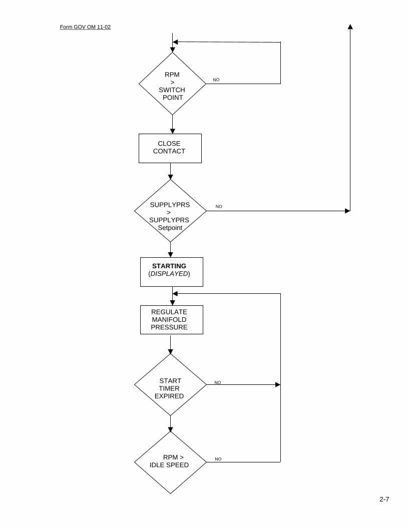
When the purge timer has expired and the supply pressure exceeds the
set point, the GOV begins controlling fuel manifold pressure for engine
starting. The fuel manifold pressure maintained for engine light off is
operator programmable. The GOV uses a separate dedicated PID control
loop to control fuel manifold pressure during starting.
After the engine fires off and achieves the programmable “IDLE SPEED”
(light-off speed) and a programmable warm-up timer expires, the GOV
uses a programmable rate internal ramp and increases fuel flow to the
engine until the minimum operating speed is achieved. When minimum
operating speed has been reached, the GOV begins to increase fuel flow
to the engine at the programmed ramp rate. When the engine speed set
point is reached, the GOV operates as an engine speed governor,
changing fuel flow as required to maintain the required speed set point.
The fuel flow will be increased until the engine speed set point has been
achieved. Thereafter, any time the speed set point is changed, the same
programmable ramp is used to accelerate or decelerate the engine. The
governor gains dynamically change based upon engine load. This feature
helps keep the engine speed as stable as possible, enhancing engine
performance and helping to keep exhaust emissions stable.
The GOV controls gas flow by changing the position of the poppet valve
very precisely. The poppet resides in a housing, which is O-ring mounted
inside the main valve body. The poppet stem is attached to a bellows.
Fuel gas pressure is admitted through a pressure regulator into the
control gas chamber. In the control gas chamber there are two small
nozzles. One of the nozzles is ported from the control gas chamber to the
enclosed side of the poppet bellowfram. The other nozzle is ported from
the control gas chamber to the down stream side of the poppet (into the
main fuel stream). One end of a small “paddle” moves between the two
nozzles.
Form GOV OM 11-02
2-4
The paddle pivots on a small torsion bar so the paddle movement is
frictionless. On the opposite end of the paddle is a voice coil. The voice
coil is surrounded by a rare earth magnet. When the computer sends
voltage through the voice coil, it moves in the magnet, pivoting the paddle
as it moves. This causes the other end of the paddle to cover one nozzle
and uncover the other. As the nozzle ported downstream of the poppet is
covered, pressure builds in the control gas chamber and on the enclosed
side of the bellowfram, forcing the poppet in the open direction. As the
nozzle ported downstream is uncovered, pressure bleeds from the control
gas chamber and the bellowfram, letting the return spring force the poppet
in the closed direction.
The GOV10/50 contain several engine safety features. The features are
listed below:
NOSIGNAL – No magnetic pick-up signal. If the frequency input from
the magnetic pick-up drops below 35 Hz for more than 250 ms while the
engine is starting or running, the governor will close and remain closed
until the start sequence is re-initiated. The terminal controls display will
annunciate the message “NOSIGNAL”. This message will be displayed
until the engine achieves a full stop and the operator presses any button
on the governor interface or the engine is restarted. LOWPRES – Low supply pressure. An alarm condition during starting or
running that if the upstream pressure drops below the governors
programmed “supply pressure setpoint”, the governor will close and
remain closed until the start sequence is re-initiated. The terminal control
display will annunciate the message “LOWPRES”. This message will
remain until the engine reaches a complete stop and the operator presses
any button the governor interface or the engine is restarted.
SAFETY SHUTDOWNS

Form GOV OM 11-02
2-5
OVRSPEED – Engine overspeed. This is an operator adjustable
setpoint for the shutdown of the engine based on RPM. If the engine
speed RPM exceeds this setpoint, the governor will shut in and remain
closed until the start sequence is re-initiated. The terminal control
display will annunciate the message “OVRSPEED”. This message will
be displayed until the engine reaches a complete stop and the operator
presses any button on the governor interface, or the engine is restarted.
THIS FEATURE SHOULD NOT BE USED AS THE PRIMARY OVERSPEED SHUTDOWN. IT IS MEANT AS A REDUNDANT SHUTDOWN DEVICE ONLY. HISTPRES – High start pressure. While starting and until the warmup
timer expires, if the manifold pressure exceeds the governor HISTPRES
setpoint, the governor will close and remain closed until the start
sequence is re-initiated. The terminal control display will annunciate
“HISTPRES” until the engine reaches a complete stop and the operator
presses any button on the governor interface, or the engine is restarted.
Form GOV OM 11-02
2-6
ENGINE NO STOPPED
STOPPED (DISPLAYED)
30 SEC. TIMER STRAIN GAUGE BAD WAIT CHECK
VALVERDY (DISPLAYED)
RPM> CRANK NO
Setpoint
YES
PURGE (DISPLAYED)
PURGE TIME
EXPIRED
Form GOV OM 11-02
2-7
RPM > NO
SWITCH POINT
CLOSE CONTACT
SUPPLYPRS NO >
SUPPLYPRS Setpoint
STARTING (DISPLAYED)
REGULATE MANIFOLD PRESSURE
START NO TIMER
EXPIRED
RPM > NO IDLE SPEED
Form GOV OM 11-02
2-8
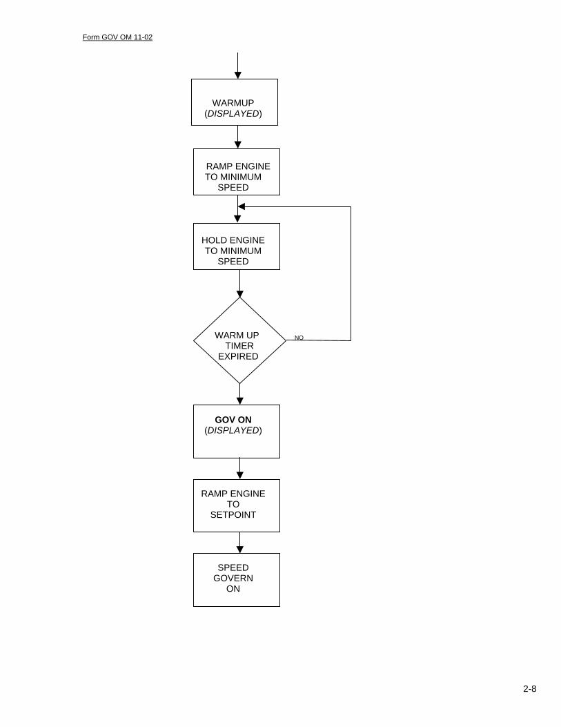
WARMUP (DISPLAYED)
RAMP ENGINE TO MINIMUM
SPEED
HOLD ENGINE TO MINIMUM
SPEED
WARM UP NO TIMER
EXPIRED
GOV ON (DISPLAYED)
RAMP ENGINE TO
SETPOINT
SPEED GOVERN
ON

Form GOV OM 11-02
3-1
Section 3 GOV INSTALLATION

Form GOV OM 11-02
3-2
1. Do not install the valve in such a manner that will trap gas pressure on the
downstream side of the valve.
2. Always provide an adequate supply pressure for the application.
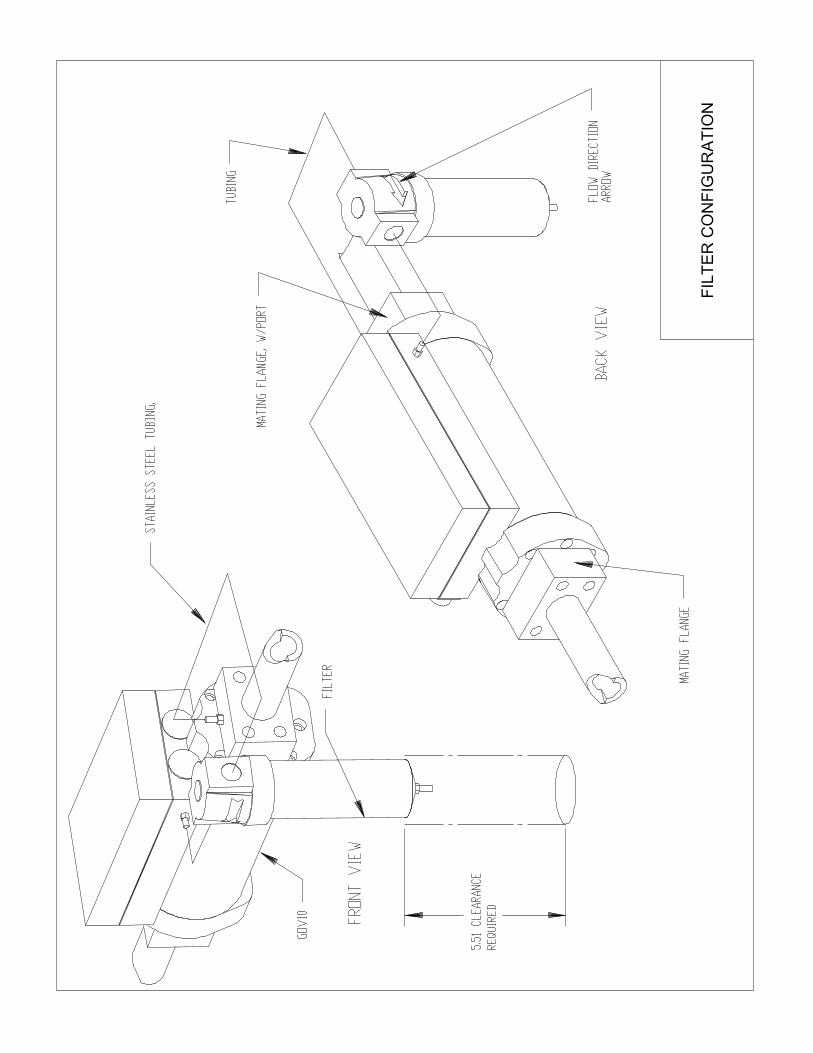
3. Where the gas is dirty, or has liquid suspension, install a separate pilot gas
supply with an external filter.
4. Supply the valve with +24 Vdc, 1.0 amp at the valve. Using small gauge
wire may cause a large voltage drop resulting in an inadequate power
supply.
5. Do not create ground loops when connecting the GOV.
6. Never install governor wires in the same conduit with any other wiring.
7. The flow signal on the GOV is loop powered.
8. Never paint the valve.
9. Never replace the valve with that of a different configuration.
10. Do not install the valve in such a manner where condensate may build up
inside the electronics housing.
NOTE: The use of resistor spark plugs and/or resistor spark plug leads is strongly recommended. This plus adherence to points 4 through 6 above will avoid most RFI noise problems.
INSTALLATION DO’S AND DON’TS

Form GOV OM 11-02
3-3
The GOV10 Gas Engine Governor is to meter fuel gas only and should not be used as a main fuel system shutoff valve. A separate fuel shutoff valve must be installed UPSTREAM of the GOV. If no venting is provided, the fuel system must be such that no gas is trapped downstream of the GOV. It is the customer’s responsibility to insure that purge times are completed and the ignition system is turned on before fuel pressure is allowed to reach the GOV.
The gas metering valve should be inspected immediately after unpacking.
Check for any damage that may have been incurred during shipping. If there
are any questions regarding the physical integrity of the valve, call the Altronic
distributor that supplied the Governor. If possible, keep the original shipping
container. If future transportation or storage of the valve is necessary, this
container will provide optimum protection.
Ensure that the GOV received matches the model no. and configuration of the
fuel valve to the packing list and if possible, to the purchase order. The top
plate of the GOV contains information pertinent to that particular valve, for
example, embedded acceleration schedule, external filter, flow feedback
information, ANSI 8-bolt flange, etc.
The GOV10/50 Governors are CSA certified for Class I, Group D, Division 1 or 2
hazardous locations.
SAFETY WARNING
VALVE PRE-INSPECTION

Form GOV OM 11-02
3-4
If the information matches correctly, then it is the appropriate Governor for your
engine application.
When considering where to place the GOV10 Gas Engine Governor it is
recommended that several issues be kept in mind.
• The valve should be located away from any extreme sources of heat.
Operating ambient temperature –40°F to +185°F / –40°C. to +85°C. Do not
expose the governor to temperatures higher than indicated here.
• Supply gas temperature will not have an effect on the flow of fuel through
the acceptable operating temperature range of the valve (see above). The
fuel gas temperature should not exceed 185°F / 85°C.
• Pressure variation in the fuel supply does not affect the gas flow through the
valve, providing that the pressure does not drop below the minimum
required for that fuel flow.
GENERAL CONSIDERATIONS

Form GOV OM 11-02
3-5
The GOV Gas Governor can be mounted in either a horizontal or vertical
position. Ideally, the installation will allow for at least 10 pipe diameters of
straight pipe (15” for 1.5” piping) on the downstream side of the valve. This
helps to ensure a consistent and smooth flow through the metering orifice,
providing a more accurate fuel flow measurement.
However, straight runs of piping to and from the valve are not required, though
some performance degradation in flow meter accuracy will result. Flow
measurement adjustments can be done to increase the accuracy of the flow
meter once the valve has been installed.
To optimize the engine’s response to fuel flow changes, mount the GOV no
more than 10 feet from the fuel manifold for optimum performance.
The valve is normally mounted and supported via the 4 or 8 bolt flanges, or the
optional mounting plate. Threaded holes (5/16”-18) are provided on the bottom
of the valve that can be used for securing the unit to a flat surface.
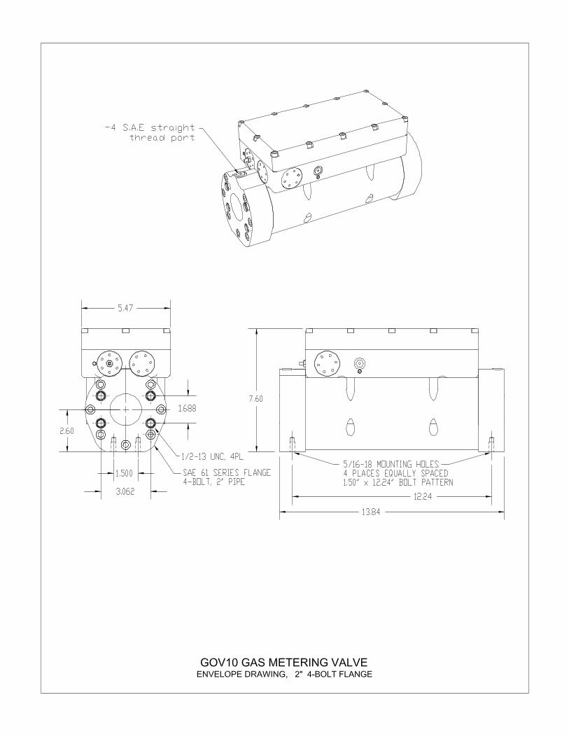
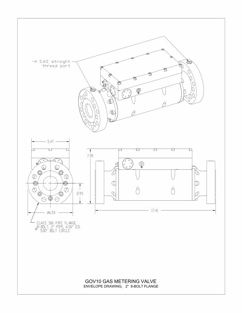
The GOV10 is supplied with SAE 61 series 4-bolt flanges for 2” pipe or ANSI
8-bolt, class 300 flanges for 2” pipe. The GOV50 is available only with the 2”,
SAE 61, 4 bolt type flanges.
Control gas pressure of at least 25 PSIG above fuel manifold pressure must be available at all times for valve actuation muscle. If fuel pressure to
the GOV inlet (upstream fuel pressure) is always the required 25 PSIG above
fuel manifold pressure (downstream pressure), the valve will operate with
internal control gas pressure from the fuel supplied to the engine. If the required
muscle gas is not available, an external gas line must be routed from an
adequate gas pressure source to the valve pilot port. Control gas is normally
bled to the downstream side of the valve. When using an external control gas
line, the line must have a shutoff valve that closes during engine shutdown.
Control gas volume required is 3 SCFM.
WARNING: Maximum gas pressure to the valve must not exceed 400 PSIG (CSA rating is for 400 PSIG).
INSTALLATION LOCATIONS
MOUNTING THE GOV GAS
METERING VALVE
GAS PRESSURE REQUIREMENTS

Form GOV OM 11-02
3-6
STANDARD INSTALLATION1
STANDARD NON-VENT INSTALLATION
1 This is the preferred installation of a GOV valve.
ANALOG FUEL CONTROL
SIGNAL
GOV10 GAS METERING
VALVE
NORMALLY CLOSED SHUTOFF VALVE
RELAY
SUPPLY ENGINE
NORMALLY OPEN VENT VALVE
VENT
s
s
ANALOG FUEL CONTROL
SIGNAL
GOV10 GAS METERING
VALVE
NORMALLY CLOSED SHUTOFF VALVE
RELAY
SUPPLY ENGINE
s s
NORMALLY CLOSED SHUTOFF VALVE

Form GOV OM 11-02
3-7
STANDARD NON-VENT INSTALLATION WITH EXTERNAL FILTER
STANDARD INSTALLATION WITH EXT. FILTER AND VENTING
ANALOG FUEL CONTROL
SIGNAL
GOV10 GAS METERING
VALVE
NORMALLY CLOSED SHUTOFF VALVE
RELAY
SUPPLY ENGINE
s s
PILOT GAS FILTER
NORMALLY CLOSED SHUTOFF VALVE
ANALOG FUEL CONTROL
SIGNAL
GOV10 GAS METERING
VALVE
NORMALLY CLOSED SHUTOFF VALVE
RELAY
SUPPLY ENGINE
NORMALLY OPEN VENT VALVE
VENT
s
s
PILOT GAS FILTER
Form GOV OM 11-02
3-8
The following sections apply to the electrical requirements of the installation of
the GOV Gas Metering Valve. All efforts should be made to conform to the
applicable electrical code with regard to hazardous environment installations.
CAUTION: The system power should be OFF before any of the valve
wiring is connected or disconnected. Failure to do so may result in
damage to your engine and/or the GOV10/50.
Hazardous locations are those areas where a potential for explosion and fire
exist because of flammable gases, vapors or finely pulverized dusts in the
atmosphere, or because of the presence of easily ignitable fibers or flyings2.
Because of the necessary requirements, the wiring methods to be used are
through threaded, ridged metal conduit with termination fittings approved for the
location. The entire assembly is to be explosion-proof and where necessary, to
employ flexible connections approved for Class I Division I.
The GOV10/50 requires 20 to 32 Vdc, 1 amp electrical power at the connector or harness. Power should be steady and uninterrupted. Power dips of any
duration below 20 volts will cause the GOV valves to close and to stay closed
until a new start sequence is initiated. The GOV electronics are electrically
isolated, but if excessive voltage noise (AC ripple) is found, it may be filtered out
using a capacitor (300 to 1000 microfarad at 50Vdc is suggested). The
capacitor should be placed at the source of the noise.
The GOV10/50 come standard with a 3/4” NPT conduit entry, and 10 feet of
leads. The threaded conduit entry is for use in electrically classified areas.
Connector pin assignments and wire colors are given in the chart on the
following page.
2 National Electric Code; articles 500-517. Canada Electric Code; section 18.
ELECTRICAL CONNECTIONS
HAZARDOUS LOCATIONS
POWER REQUIREMENTS
CONNECTION LEADS
Form GOV OM 11-02
3-9
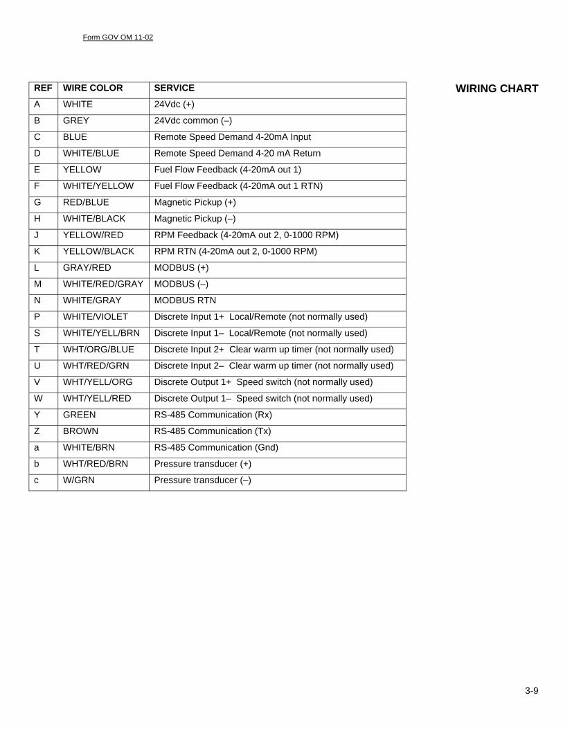
REF WIRE COLOR SERVICE
A WHITE 24Vdc (+)
B GREY 24Vdc common (–)
C BLUE Remote Speed Demand 4-20mA Input
D WHITE/BLUE Remote Speed Demand 4-20 mA Return
E YELLOW Fuel Flow Feedback (4-20mA out 1)
F WHITE/YELLOW Fuel Flow Feedback (4-20mA out 1 RTN)
G RED/BLUE Magnetic Pickup (+)
H WHITE/BLACK Magnetic Pickup (–)
J YELLOW/RED RPM Feedback (4-20mA out 2, 0-1000 RPM)
K YELLOW/BLACK RPM RTN (4-20mA out 2, 0-1000 RPM)
L GRAY/RED MODBUS (+)
M WHITE/RED/GRAY MODBUS (–)
N WHITE/GRAY MODBUS RTN
P WHITE/VIOLET Discrete Input 1+ Local/Remote (not normally used)
S WHITE/YELL/BRN Discrete Input 1– Local/Remote (not normally used)
T WHT/ORG/BLUE Discrete Input 2+ Clear warm up timer (not normally used)
U WHT/RED/GRN Discrete Input 2– Clear warm up timer (not normally used)
V WHT/YELL/ORG Discrete Output 1+ Speed switch (not normally used)
W WHT/YELL/RED Discrete Output 1– Speed switch (not normally used)
Y GREEN RS-485 Communication (Rx)
Z BROWN RS-485 Communication (Tx)
a WHITE/BRN RS-485 Communication (Gnd)
b WHT/RED/BRN Pressure transducer (+)
c W/GRN Pressure transducer (–)
WIRING CHART
Form GOV OM 11-02
3-10
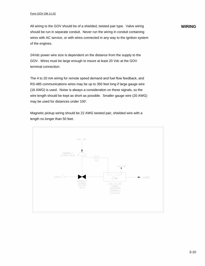
All wiring to the GOV should be of a shielded, twisted pair type. Valve wiring
should be run in separate conduit. Never run the wiring in conduit containing
wires with AC service, or with wires connected in any way to the ignition system
of the engines.
24Vdc power wire size is dependent on the distance from the supply to the
GOV. Wires must be large enough to insure at least 20 Vdc at the GOV
terminal connection.
The 4 to 20 mA wiring for remote speed demand and fuel flow feedback, and
RS-485 communications wires may be up to 350 feet long if large gauge wire
(16 AWG) is used. Noise is always a consideration on these signals, so the
wire length should be kept as short as possible. Smaller gauge wire (20 AWG)
may be used for distances under 100’.
Magnetic pickup wiring should be 22 AWG twisted pair, shielded wire with a
length no longer than 50 feet.
WIRING

Form GOV OM 11-02
3-11
The discrete output speed switch is used as a shutdown or malfunction feature
based upon low fuel gas pressure. If RPM exceeds the SPDSWICH setting and
the purge timer expires, the contact will close. In addition, the contact will open
upon any of the shutdown features programmed into the GOV 10. These
shutdowns are listed further in the manual. If engine speed drops 2 RPM below
the set point the contact will reset into the open position. This discrete output
has a 3 amp capability and is suitable for driving a small solenoid valve. Using
this contact makes possible the automation of the upstream block valve
operation. The discrete output is paralleled with the purge timer.
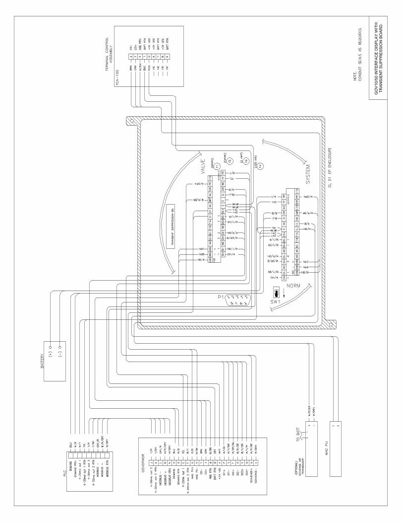
A transient suppression board (part no. TS-100) is available which provides
excellent isolation to/from the Governor and its associated control system. If
protection is necessary to achieve Class I, Division I or II electrical standards,
the transient suppression board and an approved explosion-proof (ExP) box
should be considered. The ExP box (part no. 810080) is available from Altronic
or may be supplied by the user. The recommended box for use with the
transient suppression board is Adalet model no. XJWH or equivalent
Wiring diagrams and layouts are available at the back of this manual.
TRANSIENT SUPPRESSION

Form GOV OM 11-02
4-1
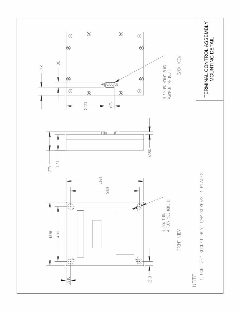
Section 4 DISPLAY TERMINAL ASSEMBLY (TCA-100)
SETPOINT
SPEED
- +DISPLAY
INPUT
MODE

Form GOV OM 11-02
4-2
The Governor Display Terminal Assembly is a small panel used for man-machine interface with the GOV governors. The front of the Display
Terminal consists of two (2) LED displays and six (6) function keys. The
top LED always displays numeric values and the bottom LED always
displays the name of the value being displayed on the top LED or a
status message such as “Valve ready” or “Gov On”. The function keys
are arranged in three (3) groups with two (2) keys in each group. The
function key groups are labeled DISPLAY, SET POINT, and MODE. In
the DISPLAY group the key functions are designated as INPUT and are
labeled with an UP ARROW on one key and a DOWN ARROW on the
other. These two keys are used to scroll up or down though the
parameters displayed on the terminal. In the SET POINT group, the
keys function is designated as SPEED (the most often used function
used is the changing of the speed setpoint). The associated keys are
labeled with a plus (+) and (-) signs. The purpose of these keys is to
change the value of any programmable parameter displayed in the LED
box. The (+) key will increment the value and the (-) key will decrement
the associated value. In the MODE group, the keys are designated SET
UP and NORM. When the NORM key is pressed, read only values are
displayed. When the SET UP key is used, the operator has access to
the programming values and may edit them.
The GOV Gas Engine Governor controls fuel flow to the engine, and thus
engine speed, by using PID control loops. PID control loops are
commonly used in the instrumentation/control industry to control a variety
of functions. PID stands for proportional, integral and derivative control.
These control loops are a way of combining three gains (though only
proportional and integral are the most commonly used) to change one
output level.
Proportional Control – proportional control is an adjustment of engine
speed determined by the relationship of engine speed (Ng) to the speed
set point. Actual RPM from the RPM set point causes an error signal.
This error signal is the engine speed adjustment. The control loop is
scaled to a full-scale output. The error signal is multiplied against the
proportional gain to generate a portion of the full-scale output.
DESCRIPTION
SETTING GAINS
Form GOV OM 11-02
4-3
Thus, the greater the error (Ng vs. set point), the greater the response
(an increase/decrease in speed). Due to response lags in the system
(includes engine), proportional control can only be adjusted a limited
amount. When proportional gain is set above the maximum the system
will tolerate, speed instability will result.
Integral Control – to add more gain to a PID control loop without
causing instability, an integrator is used. An integrator adds gain to the
control loop output in even integrals of time. Thus the larger the error,
the larger the integral contribution becomes, and the system output
increases more rapidly. Also, when the error returns to zero, the
integrator will not return to its original value until the error transitions from
a positive error to a negative error before an increasing integrator will
begin decreasing, or vice versa.
There are a few things to remember when setting governor gains. A
speed governor is receiving speed information only. A speed governor is
a reactionary device. The governor cannot anticipate when a speed
change is to occur, only after a speed change has occurred. A speed
governor only recognizes speed and the governor corrects fuel flow to
achieve the set point. On a loaded engine, if the power cylinders misfire,
speed will drop very rapidly (in one crankshaft revolution or less). The
GOV cannot prevent rapid speed drops caused by misfires, it can only
add fuel to the manifold to help the remaining cylinders pick up the load
and correct the engine speed back to the set point. DO NOT CONFUSE
ENGINE INSTABILITY CAUSED BY GAINS SET TOO HIGH WITH
SPEED CHANGES CAUSED BY MISFIRES. Gains instability is
characterized by steady speed oscillations, with error amplitude in both
directions (positive/negative) and remaining constant. Speed changes
caused by engine misfires are characterized by their erratic error
amplitude and frequency. If speed instability is present, gains need to be
lowered. If misfiring is present and cannot be corrected, the gains will
have to be as high as possible.

Form GOV OM 11-02
4-4
Governor gains set high enough to allow good load change response at
full load and speed conditions will often cause speed instability at
minimum speed and no load. To compensate for this fact, the GOV Gas
Engine Governor has available a separate set of PID gains for use at
minimum speed and no load. These gains are called IDLE GAIN and
IDLE INTG. To set the IDLE GAIN and IDLE INTG the following steps
should be done:
1. Set the GOV to LOCAL MODE.
2. The GOV factory default for these gains is 25. With a gain this low
it may take the engine far too long to accelerate to minimum speed.
If this is the case, set the IDLE GAIN and IDLE INTG to 30. The
IDLE GAIN and IDLE INTG may be changed while the engine is
running.
3. Unload the engine and set the speed set point to the minimum
speed value.
4. While watching engine speed fluctuation, begin to raise the IDLE
GAIN by a value of ten at a time. At this time, do not be concerned
with how long a speed error persists (corrected later), only with
how great the error amplitude is. If speed fluctuation does not
change, keep raising the IDLE GAIN until the fluctuation gets either
better or worse. If speed fluctuation lessens (gets better), keep
raising IDLE GAIN until the fluctuations starts to increase (get
worse). When this happens, lower the IDLE GAIN by a value of 1
or 2 at a time until such time as the engine speed fluctuation is at a
minimum. IDLE GAIN is now at its optimum setting. If speed
fluctuations increase the first time you raise IDLE GAIN, work this
procedure in reverse, i.e. lower IDLE GAIN until an improvement is
made, then worsens, then raise IDLE GAIN gradually until the
optimum setting is reached.
5. Now when a speed error occurs (even if the error is a small one)
notice how long the engine speed remains off the set point. Begin
raising the IDLE INTG by a value of ten at a time until recovery to
set is faster (gets better). Keep raising the IDLE INTG until the
engine speed begins to “overshoot” each time the governor makes
a correction. Then lower the IDLE INTG by values of 1 or 2 until
the “overshoot” disappears. IDLE INTG is then at its optimum
setting.
GAINS WITH THE ENGINE IDLING
AND AT NO LOAD
Form GOV OM 11-02
4-5
Once most engines are running well unloaded at minimum speed, they
must be sped up before attempting a load. When an engine is running
above minimum speed, different gains are needed to run the engine well
at operating speed during and after loading. Some engines are hard to
keep stable at operating speed unloaded if the gains are set to work well
when the engine is loaded. To ease this situation, the GOV uses a
function called LOAD GAIN. LOAD GAIN is a number, which is
multiplied against the fuel flow and is added to the integral gain, thus
increasing integral gain more when the engine is loaded then when it is
unloaded.
The Governor Terminal Interface Assembly displays the GOV’s
proportional gain as PROP GAIN and its integral gain as INTR GAIN.
Initially, run the engine at normal operating speed unloaded. To set
PROP GAIN and INTR GAIN the following procedure should be
performed.
1. Set LOAD GAIN as in previous section above.
2. Using the previous procedure, adjust the PROP GAIN instead of
IDLE GAIN and INTR GAIN in place of IDLE INTR. Get the engine
speed as stable as possible with the engine unloaded.
3. Load the engine. If the engine will not load up without dying, try
increasing LOAD GAIN value by 2 each time. If the engine speed
becomes unstable at no load before the engine loads well, you will
have to start lowering the LOAD GAIN and increasing INTG GAIN
until both conditions have been satisfied. PROP GAIN and INTR
GAIN may be adjusted while the engine is running.
4. Usually, once an engine is loading up it will unload satisfactorily
also. Watch the engine RPM’s as the engine unloads. Engine
speed will increase some, but should return to the setpoint quickly.
USING LOAD GAIN EFFECTIVELY
GAINS WITH THE ENGINE AT SPEED
AND LOADED
Form GOV OM 11-02
4-6
The GOV10/50 Governors provide fuel flow measurement as an option.
The measurement is calculated using differential pressure across an
orifice plate in the valve body. The governors are calibrated to a flow
standard using compressed air on a flow bench assembly. The accuracy
of orifice plate measurements is always subject to piping configuration
errors. Normally at least 10 pipe diameters of straight pipe is required
before the orifice plate to maintain accuracy. This is often impractical to
do when installing the GOV on an engine. The best way to insure
accuracy is to measure fuel flow to the engine with a meter run, turbine
meter or other flow measurement device. Compare the resultant flow
values with those of the GOV Gas Engine Governor. If an error is
present the FLOW OFFSET and FLOW ADJUST settings can be used to
correct the error.
1. Run the engine unloaded and at minimum speed. Record the flow
readings from the GOV and the independent flow measurement
device.
2. Run the engine at full load and at maximum speed, again recording
the fuel flow values.
3. Increase or decrease the FLOW ADJUST value until the flow
readings are acceptably close.
4. If flow accuracy is a concern while the engine is unloaded, re-record flow values when the engine is running unloaded. Use the
FLOW OFFSET (increase or decrease) until the readings are again
acceptably close.
5. Load the engine again and compare the fuel flow readings. If
necessary, change the FLOW ADJUST value until the readings are
matching.
6. Continue the procedure until the fuel flow readings in both the
unloaded and loaded conditions. This procedure is similar to setting
zero and span on other measurement devices. Changing the
FLOW OFFSET at the low end will change the flow reading at the
upper limit. Changing FLOW ADJUST at the upper limits will also
change the fuel flow readings on the lower limits. Each repetition
of changes will decrease the error on both ends until the loaded
and unloaded fuel flow readings are acceptable.
FUEL FLOW MEASUREMENT
Form GOV OM 11-02
4-7
VIEWING DATA NAMES AND VALUES
The Governor Terminal Interface Assembly’s bottom LED always
displays the parameter name of the value displayed in the top LED. For
instance, when the bottom LED displays “RPM”, the value being
displayed in the top LED is engine speed in revolutions per minute.
SCROLLING DATA POINTS
Press the NORM button. Press the key slowly several times. Notice
the parameter names change in the bottom LED and the corresponding
numeric values in the top LED. Pressing the key will scroll through
the display in the reverse order. By pressing the SET UP key, then the
arrow keys, a different list of parameters is available for display.
CHANGING VALUES
Press the SET UP key. Using the key, scroll the data points until
reaching “SET RPM”. If the top LED value is less than the maximum
engine RPM, use the + key until the value reaches the desired setting.
The same is available with the – key if the desired value is less than the
current setting. All programmable settings of the GOV Gas Engine
Governors are set in this manner. If the operator presses no key within
45 seconds of accessing another menu (setup or programming), the
control interface display will default to the NORM operating position (see
next page).
KEY PAD OPERATIONS
Form GOV OM 11-02
4-8
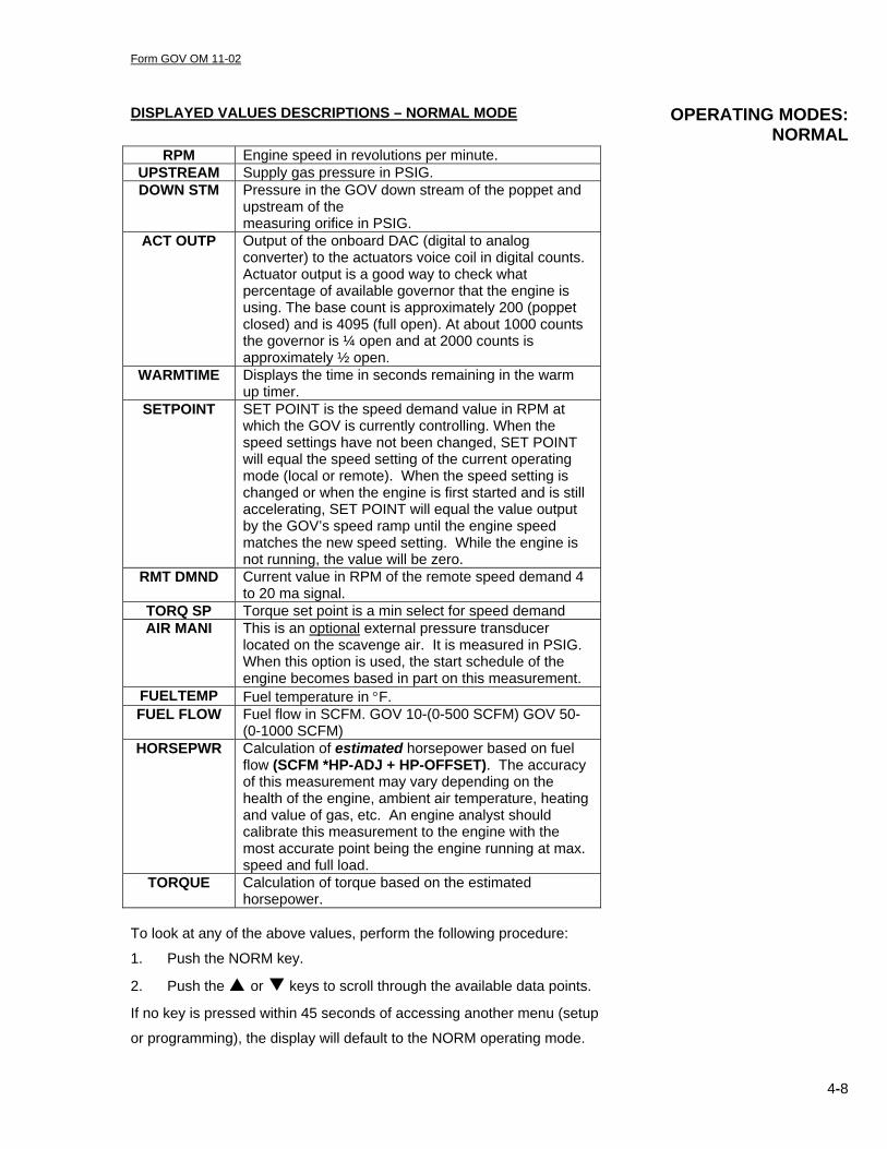
DISPLAYED VALUES DESCRIPTIONS – NORMAL MODE
RPM Engine speed in revolutions per minute. UPSTREAM Supply gas pressure in PSIG. DOWN STM Pressure in the GOV down stream of the poppet and
upstream of the measuring orifice in PSIG.
ACT OUTP Output of the onboard DAC (digital to analog converter) to the actuators voice coil in digital counts. Actuator output is a good way to check what percentage of available governor that the engine is using. The base count is approximately 200 (poppet closed) and is 4095 (full open). At about 1000 counts the governor is ¼ open and at 2000 counts is approximately ½ open.
WARMTIME Displays the time in seconds remaining in the warm up timer.
SETPOINT SET POINT is the speed demand value in RPM at which the GOV is currently controlling. When the speed settings have not been changed, SET POINT will equal the speed setting of the current operating mode (local or remote). When the speed setting is changed or when the engine is first started and is still accelerating, SET POINT will equal the value output by the GOV’s speed ramp until the engine speed matches the new speed setting. While the engine is not running, the value will be zero.
RMT DMND Current value in RPM of the remote speed demand 4 to 20 ma signal.
TORQ SP Torque set point is a min select for speed demand AIR MANI This is an optional external pressure transducer
located on the scavenge air. It is measured in PSIG. When this option is used, the start schedule of the engine becomes based in part on this measurement.
FUELTEMP Fuel temperature in °F. FUEL FLOW Fuel flow in SCFM. GOV 10-(0-500 SCFM) GOV 50-
(0-1000 SCFM) HORSEPWR Calculation of estimated horsepower based on fuel
flow (SCFM *HP-ADJ + HP-OFFSET). The accuracy of this measurement may vary depending on the health of the engine, ambient air temperature, heating and value of gas, etc. An engine analyst should calibrate this measurement to the engine with the most accurate point being the engine running at max. speed and full load.
TORQUE Calculation of torque based on the estimated horsepower.
To look at any of the above values, perform the following procedure:
1. Push the NORM key.
2. Push the or keys to scroll through the available data points.
If no key is pressed within 45 seconds of accessing another menu (setup
or programming), the display will default to the NORM operating mode.
OPERATING MODES: NORMAL

Form GOV OM 11-02
4-9
SCALING The scaling for fuel flow feed back is as follows
• GOV10 0-500 SCFM
• GOV50 0-1000 SCFM
The scaling for RPM feedback is 0-1000 RPM.
The scaling for HP feedback is 0-10,000 HP.
The scaling for Torque feedback is 0-180,000 ft.lbs. DISPLAYED DIAGNOSTIC MESSAGE POWER UP Displayed when the valve is powered up with >19Vdc
and remains displayed until any key is depressed. WAIT Displayed when pressure is trapped downstream of
the valve or if a transducer has failed. OVERPRESS Displayed when down stream pressure exceeds the
over pressure set point. HI PRESS Displayed when down stream pressure exceeds the
Hi start pressure set point. OVERSPED Displayed when RPM exceeds over speed set point. NOSIGNAL No magnetic pickup signal. If the frequency input
from the magnetic pickup drops below 35Hz from more than 250ms, the governor will close and remain closed until the start sequence is reinitiated. The control interface display will annunciate the message NOSIGNAL. This message will be displayed until the engine reaches a complete stop and the operator presses any button on the governor interface or the engine is restarted.
LOWPRES Low supply pressure. An alarm condition during starting or running. If the upstream pressure drops below the governors programmed “supply pressure” set point, the governor will close and remain closed until the start sequence is reinitiated. The control interface display will annunciate the message LOWPRES. This message will remain until the engine reaches a complete stop and the operator presses any button on the display or the engine is restarted.
TORQ S/D Unit has reached the Torque shut down set point, the Governor will close and remain closed, until the unit reaches a complete stop and the start sequence is reinitiated. The control interface display will annunciate the message TORQ S/D. this message will be displayed until the engine reaches a complete stop and the operator presses any button on the governor interface or the engine is restarted.
NOTE: Loss of 24Vdc or voltage dropping below 19Vdc will be annunciated with Version 1 software by a flashing display of OVERPRESS; with Version 2 software, the display will show POWER UP. Both flashing annunciations may be cleared by depressing NORM key after 45 seconds.

Form GOV OM 11-02
4-10
Press the SET UP key to use the setup mode. Setup mode provides a list of programmable values that the operator may change.
The following is the procedure to change the numeric values in the SET
UP mode.
1. Push the SET UP key.
2. Push the or keys to scroll through the available data
points.
3. Use the + or – keys to increment/decrement the value
indicated till the desired value is reached. For
LOCAL/REMOTE, pushing the + key will select remote
operations. Pressing the – key will enable local operations.
4. Press the NORM key to return to the Normal mode.
5. Any changes made while in the Setup Mode must be
SAVED by entering the Programming Mode and then using
the SAVE function. Unless this procedure is used, values
entered in the setup mode will take effect but will be lost if
the power is lost or cycled.
DISPLAYED VALUES DESCRIPTIONS – SETUP MODE
SET RPM 0-999 RPM
Default = 270
Governor speed set point in RPM. While in Local mode, the engine will run at the speed entered in the SET RPM.
START PS 0-50.00 PSIG Default = 4.50
The GOV will maintain fuel manifold pressure at the START PS while the engine is cranking.
SRTRATIO 0-10.00
Default = 0.00
For engines that do not have “jet assisted” starting but rather are using the equivalent of chain driven turbo chargers. This is a numeric ratio multiplied against the measured air pressure and added to the start pressure to create the starting set point (see START PS). Using the value of 0 will negate the effect of the start ratio.
SRT TIME 0-99.0 Secs. Default = 3.0
During engine start the GOV acts as a fuel regulator against the set point value (see START PS). When the engine reaches minimum operating speed the GOV switches over to a speed governor. This parameter determines the length of time (in seconds) that the GOV maintains the START PS setting (typically 3-5 seconds).
HiStPres 0-50.00 PSIG
Default = 30.00
Shut down on high fuel manifold pressure during start.
OvrPress 0-50.00 PSIG
Default = 60.00
Shut down on high fuel manifold pressure while running.
OPERATING MODES: SETUP
Form GOV OM 11-02
4-11
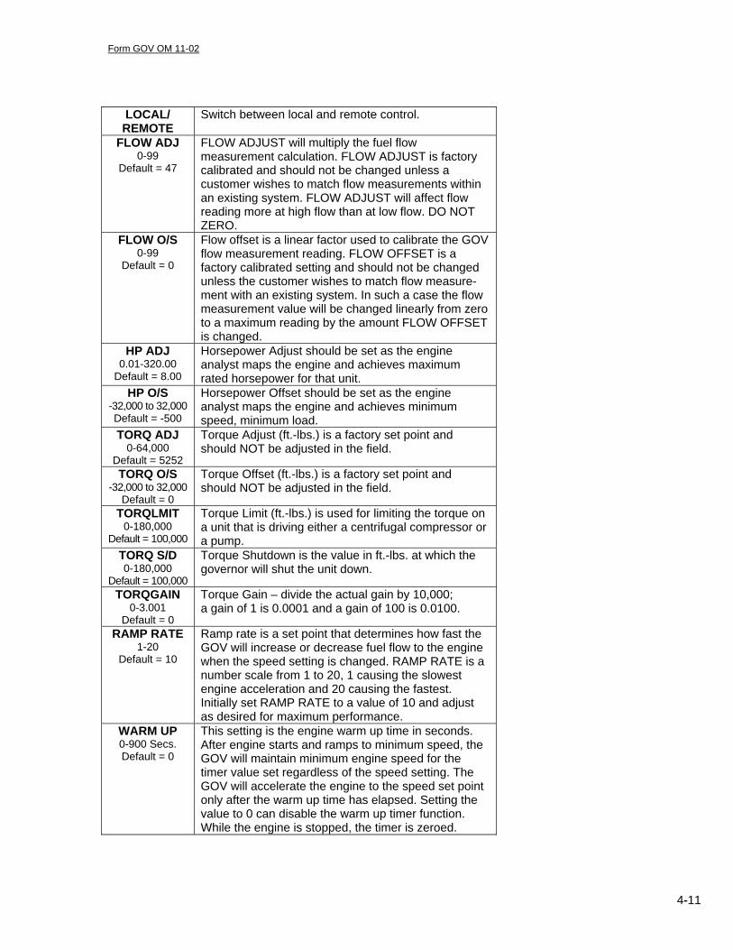
LOCAL/ REMOTE
Switch between local and remote control.
FLOW ADJ 0-99
Default = 47
FLOW ADJUST will multiply the fuel flow measurement calculation. FLOW ADJUST is factory calibrated and should not be changed unless a customer wishes to match flow measurements within an existing system. FLOW ADJUST will affect flow reading more at high flow than at low flow. DO NOT ZERO.
FLOW O/S 0-99
Default = 0
Flow offset is a linear factor used to calibrate the GOV flow measurement reading. FLOW OFFSET is a factory calibrated setting and should not be changed unless the customer wishes to match flow measure-ment with an existing system. In such a case the flow measurement value will be changed linearly from zero to a maximum reading by the amount FLOW OFFSET is changed.
HP ADJ 0.01-320.00
Default = 8.00
Horsepower Adjust should be set as the engine analyst maps the engine and achieves maximum rated horsepower for that unit.
HP O/S -32,000 to 32,000 Default = -500
Horsepower Offset should be set as the engine analyst maps the engine and achieves minimum speed, minimum load.
TORQ ADJ 0-64,000
Default = 5252
Torque Adjust (ft.-lbs.) is a factory set point and should NOT be adjusted in the field.
TORQ O/S -32,000 to 32,000
Default = 0
Torque Offset (ft.-lbs.) is a factory set point and should NOT be adjusted in the field.
TORQLMIT 0-180,000
Default = 100,000
Torque Limit (ft.-lbs.) is used for limiting the torque on a unit that is driving either a centrifugal compressor or a pump.
TORQ S/D 0-180,000
Default = 100,000
Torque Shutdown is the value in ft.-lbs. at which the governor will shut the unit down.
TORQGAIN 0-3.001
Default = 0
Torque Gain – divide the actual gain by 10,000; a gain of 1 is 0.0001 and a gain of 100 is 0.0100.
RAMP RATE 1-20
Default = 10
Ramp rate is a set point that determines how fast the GOV will increase or decrease fuel flow to the engine when the speed setting is changed. RAMP RATE is a number scale from 1 to 20, 1 causing the slowest engine acceleration and 20 causing the fastest. Initially set RAMP RATE to a value of 10 and adjust as desired for maximum performance.
WARM UP 0-900 Secs. Default = 0
This setting is the engine warm up time in seconds. After engine starts and ramps to minimum speed, the GOV will maintain minimum engine speed for the timer value set regardless of the speed setting. The GOV will accelerate the engine to the speed set point only after the warm up time has elapsed. Setting the value to 0 can disable the warm up timer function. While the engine is stopped, the timer is zeroed.
Form GOV OM 11-02
4-12
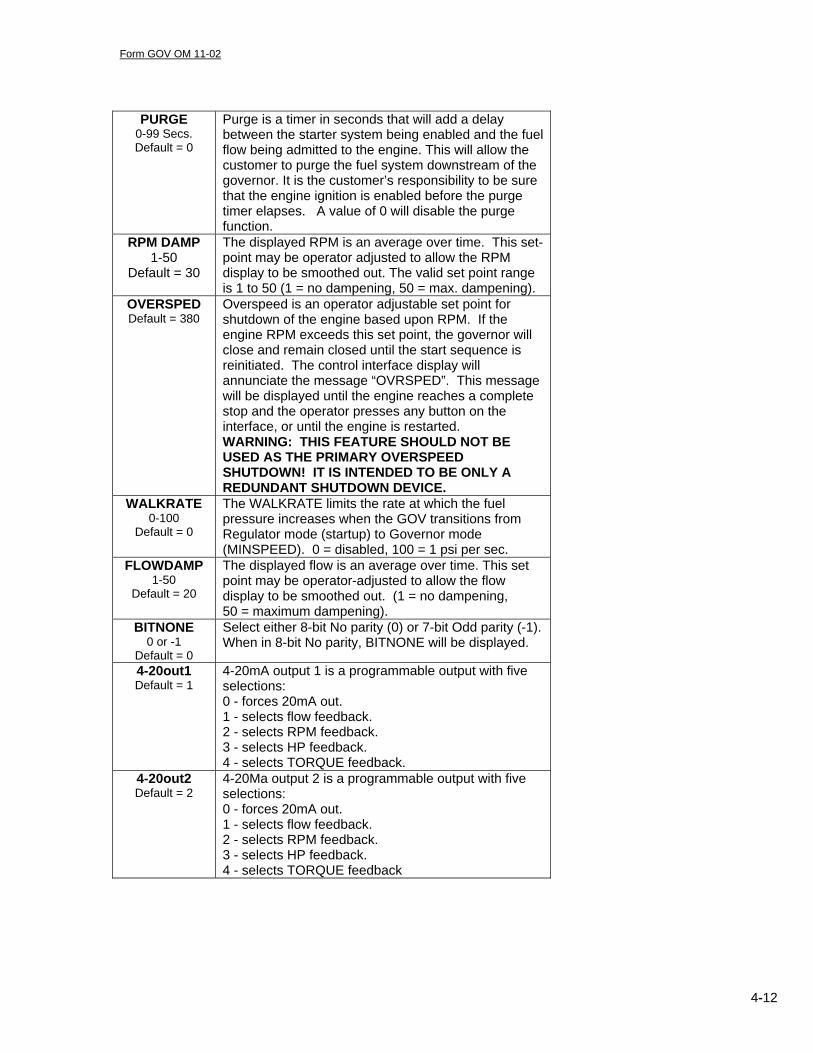
PURGE
0-99 Secs. Default = 0
Purge is a timer in seconds that will add a delay between the starter system being enabled and the fuel flow being admitted to the engine. This will allow the customer to purge the fuel system downstream of the governor. It is the customer’s responsibility to be sure that the engine ignition is enabled before the purge timer elapses. A value of 0 will disable the purge function.
RPM DAMP 1-50
Default = 30
The displayed RPM is an average over time. This set- point may be operator adjusted to allow the RPM display to be smoothed out. The valid set point range is 1 to 50 (1 = no dampening, 50 = max. dampening).
OVERSPED Default = 380
Overspeed is an operator adjustable set point for shutdown of the engine based upon RPM. If the engine RPM exceeds this set point, the governor will close and remain closed until the start sequence is reinitiated. The control interface display will annunciate the message “OVRSPED”. This message will be displayed until the engine reaches a complete stop and the operator presses any button on the interface, or until the engine is restarted. WARNING: THIS FEATURE SHOULD NOT BE USED AS THE PRIMARY OVERSPEED SHUTDOWN! IT IS INTENDED TO BE ONLY A REDUNDANT SHUTDOWN DEVICE.
WALKRATE 0-100
Default = 0
The WALKRATE limits the rate at which the fuel pressure increases when the GOV transitions from Regulator mode (startup) to Governor mode (MINSPEED). 0 = disabled, 100 = 1 psi per sec.
FLOWDAMP 1-50
Default = 20
The displayed flow is an average over time. This set point may be operator-adjusted to allow the flow display to be smoothed out. (1 = no dampening, 50 = maximum dampening).
BITNONE 0 or -1
Default = 0
Select either 8-bit No parity (0) or 7-bit Odd parity (-1). When in 8-bit No parity, BITNONE will be displayed.
4-20out1 Default = 1
4-20mA output 1 is a programmable output with five selections: 0 - forces 20mA out. 1 - selects flow feedback. 2 - selects RPM feedback. 3 - selects HP feedback. 4 - selects TORQUE feedback.
4-20out2 Default = 2
4-20Ma output 2 is a programmable output with five selections: 0 - forces 20mA out. 1 - selects flow feedback. 2 - selects RPM feedback. 3 - selects HP feedback. 4 - selects TORQUE feedback
Form GOV OM 11-02
4-13
Some set points in the GOV software are critical to the governor
operation and once set should not be changed. These set points can
only be accessed in the programming mode. If changing programming
mode set points is required by the customer, they should be changed
only after fully reading the description of the values.
To change the settings in programming mode do the following steps:
1. Enter programming mode by simultaneously pressing the
3RD , 4TH and 6TH keys, counting left to right.
2. Use the or keys to scroll to the appropriate setting.
3. Use the + or – keys to adjust the numeric value to the new
value.
4. Use SAVE function of the programming mode to save value.
When the display reads “SAVE”, press the NORM key to
save all values entered in the setup and/or programming
modes, and to resume operations.
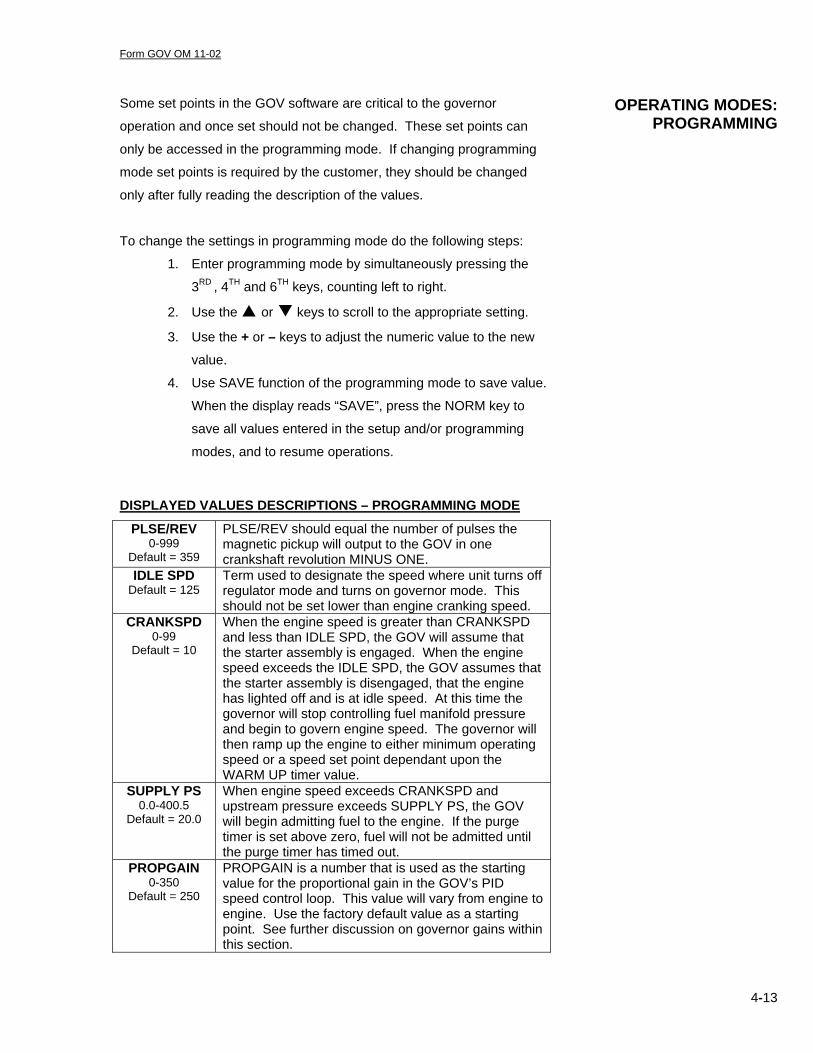
DISPLAYED VALUES DESCRIPTIONS – PROGRAMMING MODE
PLSE/REV 0-999
Default = 359
PLSE/REV should equal the number of pulses the magnetic pickup will output to the GOV in one crankshaft revolution MINUS ONE.
IDLE SPD Default = 125
Term used to designate the speed where unit turns off regulator mode and turns on governor mode. This should not be set lower than engine cranking speed.
CRANKSPD 0-99
Default = 10
When the engine speed is greater than CRANKSPD and less than IDLE SPD, the GOV will assume that the starter assembly is engaged. When the engine speed exceeds the IDLE SPD, the GOV assumes that the starter assembly is disengaged, that the engine has lighted off and is at idle speed. At this time the governor will stop controlling fuel manifold pressure and begin to govern engine speed. The governor will then ramp up the engine to either minimum operating speed or a speed set point dependant upon the WARM UP timer value.
SUPPLY PS 0.0-400.5
Default = 20.0
When engine speed exceeds CRANKSPD and upstream pressure exceeds SUPPLY PS, the GOV will begin admitting fuel to the engine. If the purge timer is set above zero, fuel will not be admitted until the purge timer has timed out.
PROPGAIN 0-350
Default = 250
PROPGAIN is a number that is used as the starting value for the proportional gain in the GOV’s PID speed control loop. This value will vary from engine to engine. Use the factory default value as a starting point. See further discussion on governor gains within this section.
OPERATING MODES: PROGRAMMING
Form GOV OM 11-02
4-14
INTRGAIN 0-350
Default = 0
INTRGAIN is a number that is used as the starting value for the integral gain in the GOV’s PID speed control loop. This value will vary from engine to engine. See further discussion on governor gains within this section.
LOADGAIN 0-99
Default = 25
LOADGAIN is a value that is multiplied by fuel flow in SCFM and is added to the integral gain in the GOV’s PID speed control loop. LOADGAIN allows higher gains to be used when the engine is under load vs. unloaded conditions.
IDLEGAIN 0-999
Default = 25
IDLEGAIN is the starting value used for proportional gain when SETPOINT equals MINSPEED. IDLEGAIN has no effect on governor performance when the engine is running above the minimum speed. See further discussion on governor gains within this section.
IDLEINTG 0-999
Default = 25
IDLEINTG is the starting value used for integral gain when SETPOINT equals MINSPEED. IDLEINTG has no effect on governor performance when the engine is running above the minimum speed. See further discussion on governor gains within this section.
POS PROP 40-125
Default = 70
Proportional gain for position control.
PRESGAIN 0-350
Default = 100
Proportional gain for pressure control.
PRES INTR 0-350
Default = 50
Integral gain for pressure control.
MAX INTR 0-16,000
Default = 16,000
MAXINTR is used as a limit on the GOV’s PID loop integrator value. This limit prevents integrator windup. The default value is 16000 and works well in most cases.
MAXSPEED 0-999
Default = 330
MAXSPEED should be programmed to the maximum normal operating speed of the engine. The GOV will not allow the LOCAL MODE speed set point to be set greater than MAXSPEED.
MINSPEED 0-999
Default = 270
MINSPEED should be programmed to the minimum normal operating speed of the engine. The GOV will not allow the LOCAL MODE speed set point to be set less than MINSPEED.
SWTCHRPM 0-999
Default = 167
Threshold for dry contact closure, Discrete output 1.
ModbsAdr Default = 1
ModBus Address.
SAVE When the display reads SAVE, press the NORM button to store all parameters currently programmed in the GOV into non-volatile flash memory. After SAVE has been performed, all values will be retained even if power to the GOV is turned off. Use the SAVE function only with the engine stopped. If the display should “lock up” when the SAVE feature is used during running conditions (due to RFI noise), the engine must be shut down and the power reset to the GOV.

Form GOV OM 11-02
4-15
It is recommended that the operator have a good working knowledge of
the engine to initialize these values. The values of starting pressures for
the listed engines below are for guideline purposes only.
• Clark 5 to 6 PSIG • Cooper Bessemer 2-cycle1 7 to 8 PSIG • Cooper Bessemer GMV/GMW2 See note 2 • Ingersoll Rand KVS, KVSR 3 to 4.5 PSIG • Ingersoll Rand KVT 1.5 to 2 PSIG • Superior 0.5 to 1.5 PSIG
The engines will usually light off with these pressures. If the engine
ignites but does not gain enough speed to keep running, increase the
START PS not more than 1 PSIG at a time until the engine maintains a
running condition.
If the engine lights off and immediately gains too much speed, decrease
START PS by ½ to 1 PSIG at a time until the engine ramps up speed
smoothly to the idle speed set point.
If the engine does not seem to be firing at all, do NOT arbitrarily increase
the START PS until ignition occurs. Be sure that the ignition system is
turned on. Watch the UPSTREAM pressure to be sure the fuel is being
turned on to the GOV. Be sure that the GOV has the required 25 PSIG
supply pressure above the manifold pressure.
SAVE and re-enter the NORM mode.
NOTE: DO NOT START THE ENGINE WHILE IN SETUP MODE.
1 Cooper 2-cycle engines with air injection valves may leak starting air pressure into the fuel manifold. On these units, roll the engine on starting air and leave the fuel turned off. Read DWNSTREAM on the display. Set START PS 7 to 8 PSIG above the DWNSTREAM pressure with the fuel turned off. 2 Procedure for determining start pressure on GMV-GMW engines: The start pressure on these engines will vary greatly depending on the amount of manifold backpressure. This backpressure is caused during the crank sequence by the starting air in the cylinders, which bleeds through the fuel inlet valve to the manifold. The correct start pressure is 2 to 8 psig above the backpressure. To determine the backpressure, crank the engine with the main fuel valve upstream of the GOV in the off position. View the DWNSTRM reading on the governor display during an attempted start. This value corresponds to the manifold backpressure. Re-enable the fuel system. Set the starting pressure at 2.0 psi above the measured backpressure reading. Attempt an engine start. If the fuel is too lean, increase the start pressure by 1 psi. If 8 psi or more is programmed the manifold backpressure, other errors exist within the engine control system. System checks on ignition, turbo and/or jet assist are necessary. DO NOT START THE ENGINE WITH THE ABOVE CONDITION AS ENGINE DAMAGE MAY OCCUR.
SETTING START PRESSURE

Form GOV OM 11-02
4-16
To set the pulses per revolution (PLSE/REV), the number of holes on the
engine flywheel must be known or how many gear teeth will pass the
magnetic pickup in one crankshaft revolution. If a gear is being used, the
gear ratio must be used in calculating the revolutions.
1. Enter programming mode from the Terminal Interface Assembly.
2. Use the or keys to scroll to the appropriate setting.
3. Use the + or – keys to adjust the numeric value to the new value.
The value must be one less than the actual number of pulses
present from the engine.
4. SAVE and re-enter NORM mode.
CRANK SPD tells the GOV Gas Engine Governor that a start sequence
has been initiated. CRANK SPD is a numeric value entered as RPM. A
value of 10 to 25 is generally acceptable. If the engine does not turn
very fast on the starter mechanism (50 RPM or less), set the CRANK
SPD closer towards a value of 10 RPM. If the engine turns faster on the
starter (90 to 100 RPM), set the CRANK SPD value towards 25 RPM.
1. Enter programming mode from the Terminal Interface Assembly.
2. Use the or keys to scroll to the appropriate setting.
3. Use the + or – keys to adjust the numeric value to the new value.
4. SAVE and re-enter NORM mode.
SUPPLYPRS tells the GOV when the main fuel block valve has been
opened. SUPPLYPRS is a numeric value entered in PSIG. When
UPSTREAM (pressure) is greater than SUPPLYPRS, the GOV will begin
to admit fuel to the manifold and maintaining DWNSTRM to START
PRS. The initial SUPPLY PRS value should be 10 psi below the actual
operating pressure.
The following is the sequence to set the SUPPLY PRS.
1. Enter programming mode from the Terminal Interface Assembly.
2. Use the or keys to scroll to the appropriate setting.
3. Use the + or – keys to adjust the numeric value to the new value.
4. SAVE and re-enter NORM mode.
SETTING PULSES PER REVOLUTION
SETTING CRANK SPEED VALUE

Form GOV OM 11-02
5-1
Section 5 GOV MAINTENANCE

Form GOV OM 11-02
5-2
The GOV10/50 Gas Engine Governor has been designed to provide
reliable operation with a minimum amount of maintenance. To ensure
optimum performance, periodic inspection and cleaning is necessary.
Preventative maintenance issues can be integrated into the current
maintenance schedule of the engine. Most maintenance requires little
effort and no downtime of the GOV10/50 valve.
Corrective maintenance is to be done when the GOV10/50 Gas
Engine Governor begins to behave erratically. Procedures have been
generated to troubleshoot and to repair most minor issues.
• External Visual Inspection – Inspect the exterior of the valve for
loose connections, frayed wires, or major structural damage.
• Cleaning – Exterior cleaning will aid in the visual inspection of the
external casing and ensure good connections. Ethyl alcohol or
mild soapy water can be used as cleaning agents.
• Maintenance Log – To facilitate troubleshooting and to establish
service schedules, a maintenance log should be kept on the fuel-
metering valve.
• Calibration – Flow calibration of the GOV 10/50 is performed in a
controlled environment before shipment. Since calibration of the
valve requires equipment not normally available in the field, it is
recommended that the valve be returned to the Altronic distributor
serving your area.
• Pilot Gas Filter – The internal pilot gas filter, if installed should be
changed every six (6) months or more frequently if necessary.
The only corrective maintenance procedures that field personnel may
be able to perform on the GOV 10/50 Gas Engine Governor are that of
regulator and pilot filter cleaning/replacing and poppet valve assembly
removal. Any other actions taken on the GOV 10/50 valve may cause
physical damage or loss of calibration and would require that the valve
be serviced for refitting or re-calibration.
MAINTENANCE OF THE GOV10/50 GAS ENGINE
GOVERNOR
PREVENTATIVE MAINTENANCE OF THE GOV10/50 GAS ENGINE
GOVERNOR
CORRECTIVE
MAINTENANCE ON THE GOV10/50 GAS ENGINE
GOVERNOR

Form GOV OM 11-02
5-3
The following section will cover the replacement or cleaning of the
Regulator assembly. Before starting it is recommended that a clean
flat work surface be prepared and the proper tools available. It is also
recommended that Valve Repair Kit be purchased which contains
items such as a spanner wrench, replacement O-rings, replacement
filter and O-ring lube.
Procedure for the cleaning/replacing of pilot filter 1. Using the spanner wrench, apply pressure in a counter-clockwise
motion and remove the regulator assembly.
2. DO NOT remove the regulator adjustment screw and nut. If these
are removed, the correct regulator settings (42 psid) cannot be
reset without returning the valve for re-calibration.
3. Check to see that the regulator does not interfere with the end
flanges. If there is no interference, continue to step 5. If there is
interference, the inlet flanges need to be removed (step 4).
4. Remove the 7 cap screws holding the inlet flange on using a 5/16”
Allen wrench. Remove the flange.
5. The filter O-ring (size 4470-200-012) and filter should now be
visible.
REGULATOR & FILTER CLEANING OR
REPLACEMENT

Form GOV OM 11-02
5-4
6. Carefully remove the O-ring for later use. Inspect the O-ring for
cuts and abrasions before reuse. If there is any physical damage
to the O-ring, it is to be replaced.
7. If you have a replacement filter and DO NOT want to reuse the
current filter, puncture the filter with a sharp object and remove it.
Continue to step 11.
8. If the filter is to be reused, use a dental pick to carefully ease the
filter out by its edges.
9. Backflush the filter with stoddard solvent or other cleaner.
10. Place the new or cleaned filter into the housing filter cavity, course
side down.
Form GOV OM 11-02
5-5
11. Place the O-ring in front of the filter to fasten it. When replacing or reusing an O-ring, the proper lubricant should be used at all times (i.e. Dow Corning lubricant #55).
12. Tighten the regulator assembly using the spanner wrench in
conjunction with a torque wrench (30 lb-ft of torque).
13. If the end flange had to be removed, place a small amount of O-
ring grease on the flange O-ring and re-install.
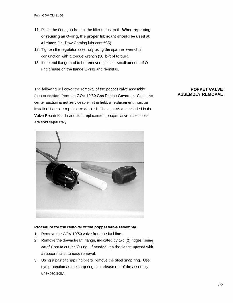
The following will cover the removal of the poppet valve assembly
(center section) from the GOV 10/50 Gas Engine Governor. Since the
center section is not serviceable in the field, a replacement must be
installed if on-site repairs are desired. These parts are included in the
Valve Repair Kit. In addition, replacement poppet valve assemblies
are sold separately.
Procedure for the removal of the poppet valve assembly
1. Remove the GOV 10/50 valve from the fuel line.
2. Remove the downstream flange, indicated by two (2) ridges, being
careful not to cut the O-ring. If needed, tap the flange upward with
a rubber mallet to ease removal.
3. Using a pair of snap ring pliers, remove the steel snap ring. Use
eye protection as the snap ring can release out of the assembly
unexpectedly.
POPPET VALVE ASSEMBLY REMOVAL
Form GOV OM 11-02
5-6
4. Using the soft, rubber coated side of the snap ring pliers, pry out
the orifice metering plate (DO NOT DAMAGE THE INNER EDGE IN ANY WAY).
5. Remove the upstream flange, being careful not to cut the O-ring.
Again, tap the flange with a rubber hammer to ease removal.
6. Put a 2” diameter PVC pipe over the downstream portion of the
center section. Using a rubber mallet, tap the PVC pipe until the
center section is removed from the housing. Do not press or turn the poppet itself.
7. Coat the O-rings (3) of the new center section with O-ring
lubricant.
8. Insert the poppet assembly into the valve body with the cone
facing in the upstream direction.
9. Align the control pressure inlet of the poppet assembly with the
dowel insert of the control pressure transducer.
10. NOTE: The cone of the assembly, which does not have a cap
screw, is in line with the control pressure inlet of the assembly.
11. Click the center section in place by providing sufficient downward
force on the center section cone. In the field, this can be done by
CAREFULLY standing on the cone portion of the center section
when it is oriented vertically.
12. Replace the upstream flange (it has two ridges). Tighten down the
7 cap screws (6 lb-ft torque each).
13. Apply O-ring lubricant to the orifice O-ring. Firmly press the orifice
into the valve body at the downstream end. Ensure that the taper
faces the downstream side of the valve.
14. Replace the snap ring.
15. Replace the downstream flange. Tighten down the 7 cap screws
(6 lb-ft torque each).
16. Return the malfunction center section for refitting.

Form GOV OM 11-02
5-7
Occasionally some form of foreign debris will make its way into the
metering housing and will become lodged inside. This will cause the
GOV 10/50 to malfunction in such ways as failure to shut-off (leakage)
and incorrect transducer readings affecting valve accuracy. Any
debris should be removed by using compressed air.
Procedure for removing foreign debris from the metering housing and poppet assembly 1. Upon the removal of the poppet assembly from the metering
housing of the GOV 10/50, inspect the housing for any internal
damage that may have occurred.
2. Shop air can be used to blow away and clean any loose particles
that may have accumulated. DO NOT use any hard-edged
instrument to clean the valve housing.
3. Holding the center section in hand, apply instrument air to the
poppet assembly through the control pressure port (Pc).
4. The poppet valve will open with 30 to 70 psi air applied. Do not
exceed this range.
5. Using a soft edged device (i.e. Popsicle stick, Q-Tip, etc) hold
open the poppet valve. Do NOT use any hard-edged instruments
(i.e. screwdrivers) as this will damage the assembly.
6. Ensuring that the poppet assembly is clear of debris, release the
poppet valve.
7. Re-lubricate the O-ring seals of the poppet assembly and reinstall
as instructed.
CAUTION: Due to the strong nature of the shutoff spring within the
center section, DO NOT place your fingers near the poppet valve if it is
in an open position.
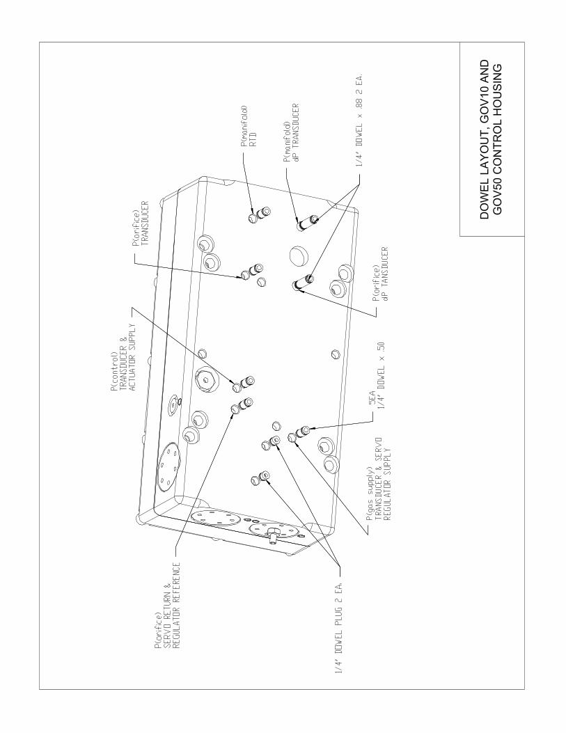
Replacement of the GOV 10/50 Fuel Gas Valve transducers can be
done in the field under the direction of the distributor or Altronic
personnel. The transducers that may be replace are the
• P(control) transducer
• P(offset) transducer
• P(supply) transducer
By replacing a transducer in the field, accuracy of the GOV 10/50 may
be slightly affected due to the small variances in transducer parts.
REMOVAL OF FOREIGN
DEBRIS FROM THE POPPET ASSEMBLY
TRANSDUCER REPLACEMENT
Form GOV OM 11-02
5-8
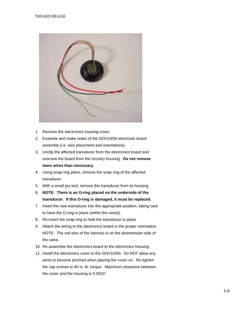
1. Remove the electronics housing cover.
2. Examine and make notes of the GOV10/50 electronic board
assembly (i.e. wire placement and orientations).
3. Unclip the affected transducer from the electronics board and
unscrew the board from the circuitry housing. Do not remove more wires than necessary.
4. Using snap ring pliers, remove the snap ring of the affected
transducer.
5. With a small pry tool, remove the transducer from its housing. 6. NOTE: There is an O-ring placed on the underside of the
transducer. If this O-ring is damaged, it must be replaced. 7. Insert the new transducer into the appropriate position, taking care
to have the O-ring in place (within the cavity).
8. Re-insert the snap ring to hold the transducer in place.
9. Attach the wiring to the electronics board in the proper orientation.
NOTE: The red wire of the harness is on the downstream side of
the valve.
10. Re-assemble the electronics board to the electronics housing.
11. Install the electronics cover to the GOV10/50. Do NOT allow any
wires to become pinched when placing the cover on. Re-tighten
the cap screws to 40 in.-lb. torque. Maximum clearance between
the cover and the housing is 0.0015”.

Form GOV OM 11-02
6-1
Section 6 DRAWINGS
Form GOV OM 11-02
6-2
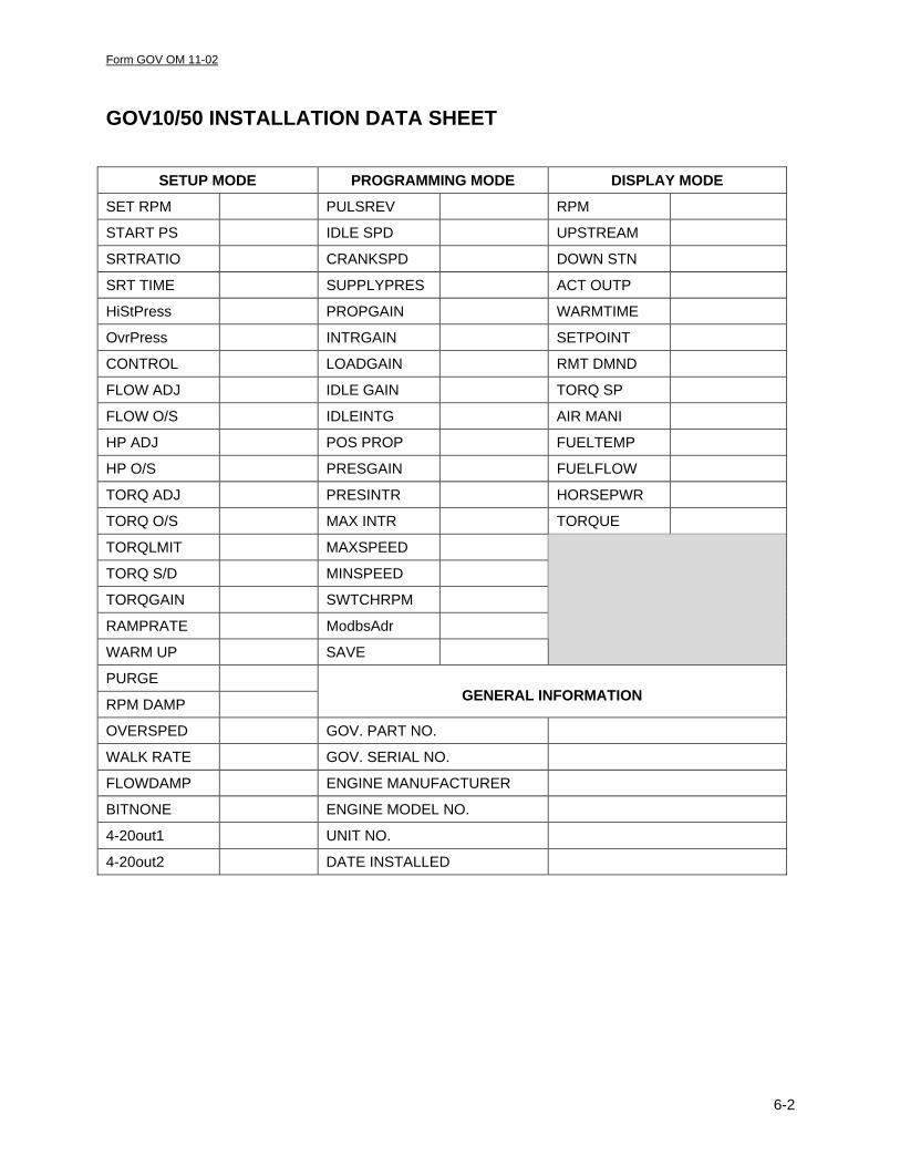
GOV10/50 INSTALLATION DATA SHEET
SETUP MODE PROGRAMMING MODE DISPLAY MODE
SET RPM PULSREV RPM
START PS IDLE SPD UPSTREAM
SRTRATIO CRANKSPD DOWN STN
SRT TIME SUPPLYPRES ACT OUTP
HiStPress PROPGAIN WARMTIME
OvrPress INTRGAIN SETPOINT
CONTROL LOADGAIN RMT DMND
FLOW ADJ IDLE GAIN TORQ SP
FLOW O/S IDLEINTG AIR MANI
HP ADJ POS PROP FUELTEMP
HP O/S PRESGAIN FUELFLOW
TORQ ADJ PRESINTR HORSEPWR
TORQ O/S MAX INTR TORQUE
TORQLMIT MAXSPEED
TORQ S/D MINSPEED
TORQGAIN SWTCHRPM
RAMPRATE ModbsAdr
WARM UP SAVE
PURGE
RPM DAMP
GENERAL INFORMATION
OVERSPED GOV. PART NO.
WALK RATE GOV. SERIAL NO.
FLOWDAMP ENGINE MANUFACTURER
BITNONE ENGINE MODEL NO.
4-20out1 UNIT NO.
4-20out2 DATE INSTALLED