Embed Size (px)
DESCRIPTION
alu DESIGN
Citation preview

ALU Design
Lecturer: Dr. Hui Annie Guo
K17-501F (ext. 57136)
COMP3211/9211 2010S1 wk3_1 P2
Overview
• Design process
• Design approaches
• Typical design techniques/tricks
– ALU
– Integer Multiplier
– Shifter
COMP3211/9211 2010S1 wk3_1 P3
Design Process
• Design begins with requirements
– Functional capabilities: what it will do
– Performance characteristics: speed, power, area, . . .
• Design finishes as assembly
– A representation that describes components used and how those components are assembled in order to meet design requirements
– To design is in fact to present
• Design is a "creative process," not a simple, linear process
– May need to iterate many times to achieve a successful design
COMP3211/9211 2010S1 wk3_1 P4
Design Approaches
• Two basic approaches used in design:– Describe via a Top-Down decomposition of complex
functions (behaviors) into more primitive functions[analysis]
– Construct through Bottom-Up composition of primitivebuilding blocks into more complex assemblies [synthesis]
• The real design approach used by designers may be a creative employment of both Top-Down and Bottom-Up approaches in the design process
CPU
Datapath Control
ALU Regs Shifter
NandGate

COMP3211/9211 2010S1 wk3_1 P5
Design as Search
• Design involves educated guesses and verification
– Given the goals, how should these be prioritized?
– Given alternative design pieces, which should be selected?
– Given design space of components & assemblies, which part will yield the best solution?
Feasible (good) choices vs. Optimal choices
Problem A
Strategy 1 Strategy 2
SubProb 1 SubProb2 SubProb3
COMP3211/9211 2010S1 wk3_1 P6
Problem: Design a “fast” ALU for the MIPS ISA
• Requirements
– Must support the Arithmetic / Logic operations
– Tradeoffs of cost and speed based on frequency of occurrence, hardware budget
COMP3211/9211 2010S1 wk3_1 P7
MIPS ALU requirements
• Add, AddU, Sub, SubU, AddI, AddIU
– 2’s complement adder/sub with overflow detection
• And, Or, AndI, OrI, Xor, Xori
– Logical AND, logical OR, XOR
• SLT, SLTI, SLTIU (set less than)
– 2’s complement adder with inverter, check sign bit of result
• Mult, MultU, Div, DivU
– Need 32-bit multiply and divide, signed and unsigned
• Sll, Srl, Sra
– Need left shift, right shift, right shift arithmetic by 0 to 31 bits
Please refer to “MIPS reference data” and Ch. 2 of P&H textbook for the instruction definition
COMP3211/9211 2010S1 wk3_1 P8
Abstraction
• Functional Specification
inputs: 2 x 32-bit operands A, B, 4-bit mode
outputs: 32-bit result S, 1-bit carry, 1 bit overflow
operations: add, addu, sub, subu, and, or, xor, slt, sltU
• Block Diagram (schematic symbol, VHDL entity)
ALUALUA B
movf
S
32 32
32
4c
COMP3211/9211 2010S1 wk3_1 P9
ALU Interface Description: VHDL
library IEEE;use IEEE.STD_LOGIC_1164.ALL;
Entity ALU is
port ( signal A, B: in std_logic_vector (0 to 31);signal m: in std_logic_vector (0 to 3);signal S: out std_logic_vector (0 to 31);signal c: out std_logic;signal ovf: out std_logic)
end ALU;
COMP3211/9211 2010S1 wk3_1 P10
Behavioral Representation: VHDL
Architecture fun_des of ALU isSignal result: std_logic(32 downto 0);Begin
...
result <= ( ‘0’& A) + (‘0’& B);S <= result(31 downto 0);
carry <= result(32);
Ovf <= '1' when (A(31)=B(31))and (result(31)/= A(31)) else '0';
...End fun_des;
COMP3211/9211 2010S1 wk3_1 P11
How to design the ALU?
• Divide and conquer
– Break the problem into simpler problems, solve them and glue together the solutions
• E.g. divide a multiple bit operation into single bit operations.
COMP3211/9211 2010S1 wk3_1 P12
Bit Based Design
• Design trick 1: Design one “slice”, capable of computing the result for 2 1-bit inputs and duplicate the design 32 times
A B
M
S
32 32
32
4
Ovflw
ALU0
a0 b0
m
cincos0
ALU0
a31 b31
m
cincos31

COMP3211/9211 2010S1 wk3_1 P13
Design with Building Blocks
• Design trick 2: take pieces you know (or can imagine) and try to put them together
A
B
1-bit
Full
Adder
CarryOut
Mu
x
CarryIn
Result
add
and
or
S-select
1-bit ALU
COMP3211/9211 2010S1 wk3_1 P14
Additional Operations (refinement)
• Design trick 3: solve part of the problem and extend
– A - B = A + (– B)
• form two’s complement by invert and add one
A
B
1-bit
Full
Adder
CarryOut
Mu
x
CarryIn
Result
add
and
or
S-selectinvert
COMP3211/9211 2010S1 wk3_1 P15
Revised Diagram
• LSB and MSB need to do a little extra
A B
M
S
32 32
32
4
Ovflw
ALU0
a0 b0
cincos0
ALU0
a31 b31
cincos31
C/L to
produce
select,
comp,
c-in
?
COMP3211/9211 2010S1 wk3_1 P16
Overflow Detection Logic
• Carry into MSB ⊕⊕⊕⊕ Carry out of MSB– For a N-bit ALU: Overflow = CarryIn[N-1] XOR CarryOut[N-1]
A0
B0
1-bit
ALUResult0
CarryIn0
CarryOut0
A1
B1
1-bit
ALUResult1
CarryIn1
CarryOut1
A2
B2
1-bit
ALUResult2
CarryIn2
A3
B3
1-bit
ALUResult3
CarryIn3
CarryOut3
Overflow
X Y X XOR Y
0 0 0
0 1 1
1 0 1
1 1 0

COMP3211/9211 2010S1 wk3_1 P17
What about performance?
• Critical Path of n-bit Ripple-carry adder is n*Td– Time complexity: O(n)
• Design Trick 4: throw hardware at it
A0
B0
1-bit
ALUResult0
CarryIn0
CarryOut0
A1
B1
1-bit
ALUResult1
CarryIn1
CarryOut1
A2
B2
1-bit
ALUResult2
CarryIn2
CarryOut2
A3
B3
1-bit
ALUResult3
CarryIn3
CarryOut3
COMP3211/9211 2010S1 wk3_1 P18
Carry Look Ahead• Design trick 5: peek
A B C-out0 0 0 “kill”0 1 C-in “propagate”1 0 C-in “propagate”1 1 1 “generate”
A0
B0
S
G0
P0
G = A and BP = A xor B
A
B
S
G
P
A
B
S
G
P
A
B
S
G
P
Cin
C1 =G0 + C0 •••• P0
C2 = G1 + G0 •••• P1 + C0 •••• P0 •••• P1
C3 = G2 + G1 •••• P2 + G0 •••• P1 •••• P2 + C0 •••• P0 •••• P1 •••• P2
G
C4 = . . .
P
COMP3211/9211 2010S1 wk3_1 P19
Cascaded Carry Look-ahead (16-bit): Abstraction
CLA
4-bitAdder
4-bitAdder
4-bitAdder
C1 =G0 + C0 •••• P0
C2 = G1 + G0 •••• P1 + C0 •••• P0 •••• P1
C3 = G2 + G1 •••• P2 + G0 •••• P1 •••• P2 + C0 •••• P0 •••• P1 •••• P2
G
P
G0
P0
C4 = . . .
C0
COMP3211/9211 2010S1 wk3_1 P20
Carry-select Adder
• Design Trick 6: Guess
n-bit adder n-bit adderO(2n) = 2*CP(n)
n-bit adder n-bit addern-bit adder 1 0
Cout
CP(2n) = CP(n) + CP(mux)
Carry-select adder
mux

COMP3211/9211 2010S1 wk3_1 P21
Carry Skip Adder
• Design Trick 7 : reduce worst case delay
4-bit Ripple Adder
A0B
SP0P1P2P3
4-bit Ripple Adder
A4B
SP0P1P2P3
Just speed up the slowest case for each block
COMP3211/9211 2010S1 wk3_1 P22
Multiply (unsigned)
• Paper and pencil example (unsigned):Multiplicand 1000
Multiplier 10011000
00000000
1000 Product 01001000
• m bits x n bits = m+n bit product
• Binary makes it easy:
– 0 => place 0 ( 0 x multiplicand)
– 1 => place a copy ( 1 x multiplicand)
• 4 versions of multiply hardware & algorithm:
– successive refinement
Implement thisprocess!
COMP3211/9211 2010S1 wk3_1 P23
Unsigned Multiplier (version 0)
Combinational logic
– Stage i accumulates A*2i if Bi=1
• How much hardware for 32 bit multiplier? Critical path length (maximum delay on any path through circuit)?
B0
A0A1A2A3
A0A1A2A3
A0A1A2A3
A0A1A2A3
B1
B2
B3
P0P1P2P3P4P5P6P7
0 0 0 0
n-bit adder
(n+1)-bit sum
COMP3211/9211 2010S1 wk3_1 P24
Unsigned Multiplier (version 1)
• Sequential logic
– 64-bit Multiplicand reg, 64-bit ALU, 64-bit Product reg, 32-bit multiplier reg
Product
Multiplier
Multiplicand
64-bit ALU
Shift Left
Shift Right
WriteControl
32 bits
64 bits
64 bits
Multiplier = datapath + control

COMP3211/9211 2010S1 wk3_1 P25
Multiply Algorithm (version 1)
Iter Product Multiplier Multiplicand
0. 0000 0000 0011 0000 0010
1. 0000 0010 0001 0000 0100
2. 0000 0110 0000 0000 1000
3. 0000 0110…
3. Shift the Multiplier register right 1 bit.
Done
Yes: 32 repetitions
2. Shift the Multiplicand register left 1 bit.
No: < 32 repetitions
1. TestMultiplier0
Multiplier0 = 0Multiplier0 = 1
1a. Add multiplicand to product &
place the result in Product register
32nd
repetition?
Start
Product
Multiplier
Multiplicand
64-bit ALU
Shift Left
Shift Right
Write
Control
32 bits
64 bits
64 bits
COMP3211/9211 2010S1 wk3_1 P26
Observations on Multiply Version 1
• 1 clock per bit => O(n) for n-bit multiply
• 1/2 bits in multiplicand register always 0
– 64-bit adder is wasted
• 0’s inserted in the right of multiplicand register as left-shifted
– least significant bits of product never changed once formed
• Instead of shifting multiplicand to left, shift product to right?
COMP3211/9211 2010S1 wk3_1 P27
Unsigned Multiplier (version 2)
• 32-bit Multiplicand reg, 32 -bit ALU, 64-bit Product reg, 32-bit Multiplier reg
Product
Multiplier
Multiplicand
32-bit ALU
Shift Right
Write
Control
32 bits
32 bits
64 bits
Shift Right
COMP3211/9211 2010S1 wk3_1 P28
Multiply Algorithm (version 2)
3. Shift the Multiplier register right 1 bit.
Done
Yes: 32 repetitions
2. Shift the Product register right 1 bit.
No: < 32 repetitions
1. TestMultiplier0
Multiplier0 = 0Multiplier0 = 1
1a. Add multiplicand to the left half of product &
place the result in the left half of Product register
32nd
repetition?
Start
Product Multiplier Multiplicand 0000 0000 0011 0010
COMP3211/9211 2010S1 wk3_1 P29
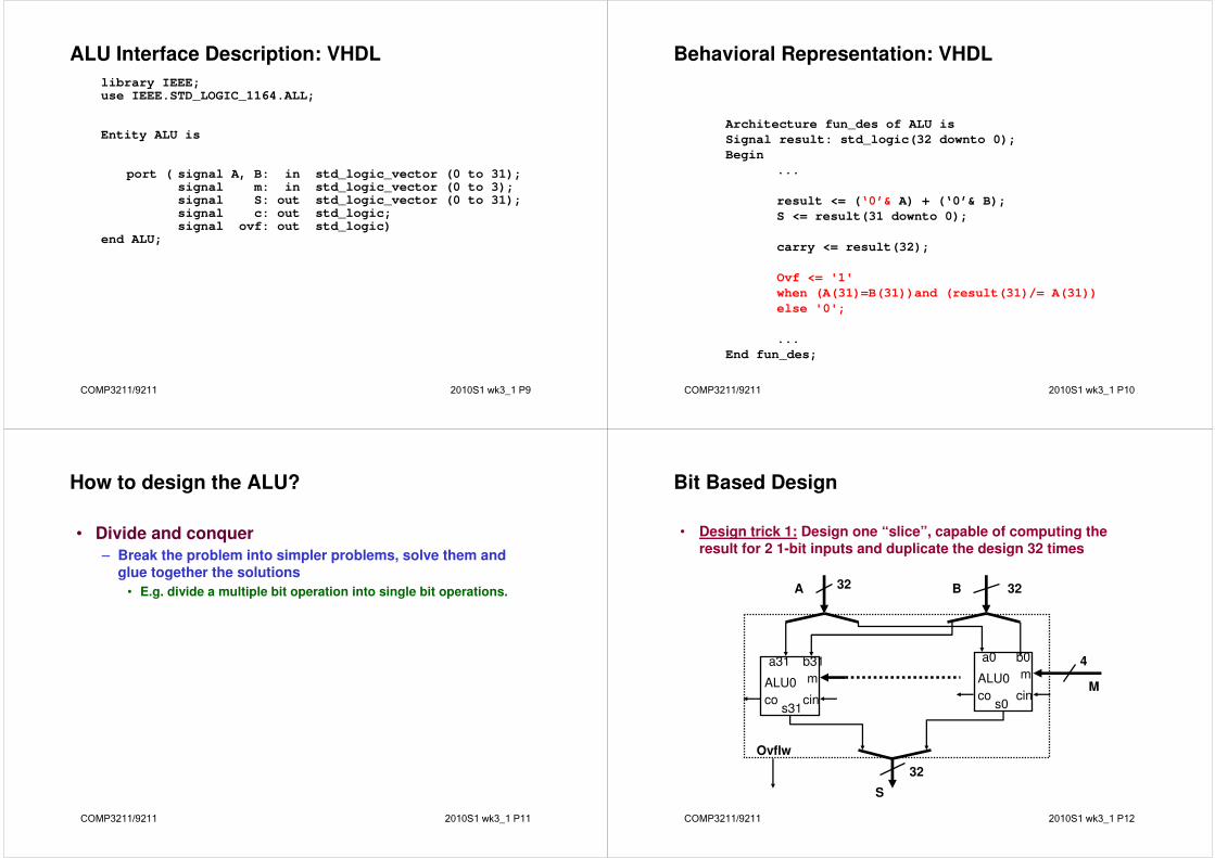
Observations on Multiply Version 2
• Product register wastes space that exactly matches size of multiplier
– combine Multiplier register and Product register
COMP3211/9211 2010S1 wk3_1 P30
Unsigned Multiplier (version 3)
• 32-bit Multiplicand reg, 32 -bit ALU, 64-bit Product reg, (0-bit Multiplier reg)
Product (Multiplier)
Multiplicand
32-bit ALU
WriteControl
32 bits
64 bits
Shift Right
COMP3211/9211 2010S1 wk3_1 P31
Multiply Algorithm (version 3)
Multiplicand Product0010 0000 0011
Done
Yes: 32 repetitions
2. Shift the Product register right 1 bit.
No: < 32 repetitions
1. TestProduct0
Product0 = 0Product0 = 1
1a. Add multiplicand to the left half of product &
place the result in the left half of Product register
32nd
repetition?
Start
COMP3211/9211 2010S1 wk3_1 P32
Observations on Multiply Version 3
• 2 steps per bit because Multiplier & Product combined
• MIPS registers Hi and Lo are left and right half of Product register
• The multiplier is for MIPS instruction MultU. What about signed multiplication?
– Booth’s Algorithm is elegant way to multiply signed numbers using same hardware as before and save cycles
• can handle multiple bits at a time

COMP3211/9211 2010S1 wk3_1 P33
Motivation for Booth’s Algorithm
Example 2 x 6 = 0010 x 0110:0010
x 0110+ 0000 shift (0 in multiplier)+ 0010 add (1 in multiplier)+ 0010 add (1 in multiplier)+ 0000 shift (0 in multiplier)
00001100
• ALU with add or subtract gets same result in more than one way:
6 = – 2 + 8 0110 = – 00010 + 01000 = 11110 + 01000
• For example
0010
x 0 1100000 shift (0 in multiplier)
– 0010 sub (first 1 in multpl.) 0000 shift (mid string of 1s)
+ 0010 add (prior step had last 1) 00001100
COMP3211/9211 2010S1 wk3_1 P34
Booth’s Algorithm
Replace a string of 1s in multiplier with an initial subtract when
we first see a one and then later add for the bit after the last one
Current Bit to Explanation Example Op
Bit the Right
1 0 Begins run of 1s 0001111000 sub
1 1 Middle of run of 1s 0001111000 none
0 1 End of run of 1s 0001111000 add
0 0 Middle of run of 0s 0001111000 none
Originally for Speed (when shift was faster than add)
–1+ 10000
01111
0 1 1 1 1 0beginning of run
end of runmiddle of run
COMP3211/9211 2010S1 wk3_1 P35
Recall: Multiply Algorithm
Done
Yes: 32 repetitions
2. Shift the Product register right 1 bit.
No: < 32 repetitions
1. TestProduct0
Product0 = 0Product0 = 1
1a. Add multiplicand to the left half of product &
place the result in the left half of Product register
32nd
repetition?
Start
COMP3211/9211 2010S1 wk3_1 P36
Booths Example (2 x 7)
1a. P = P - m 1110 + 11101110 0111 0 shift P (sign ext)
1b. 0010 1111 0011 1 11 -> nop, shift
2. 0010 1111 1001 1 11 -> nop, shift
3. 0010 1111 1100 1 01 -> add
4a. 0010 + 0010
0001 1100 1 shift
4b. 0010 0000 1110 0 done
Operation Multiplicand Product next?
0. initial value 0010 0000 0111 0 10 -> sub
Current bit
Bit to right
COMP3211/9211 2010S1 wk3_1 P37
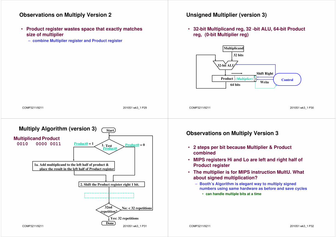
Booths Example (2 x -3)
1a. P = P - m 1110 +11101110 1101 0 shift P (sign ext)
1b. 0010 1111 0110 1 01 -> add+ 0010
2a. 0001 0110 1 shift P
2b. 0010 0000 1011 0 10 -> sub+ 1110
3a. 0010 1110 1011 0 shift
3b. 0010 1111 0101 1 11 -> nop
4a 1111 0101 1 shift
4b. 0010 1111 1010 1 done
Operation Multiplicand Product next?
0. initial value 0010 0000 1101 0 10 -> sub
Current bit
Bit to right
COMP3211/9211 2010S1 wk3_1 P38
Wallace Tree*
• An efficient hardware implementation of a digital circuit that multiplies two integers.
• Has O(logn) complexity for nxn two integer complications
• Three steps
– Bit multiply (AND)
– Reduce the bit-wise sum to multiple layers of HA or FA
• Each leave FA/HA producing one-bit sum and 1-bit carry, two wires
– Group the wires from the in two numbers, and add them with a conventional adder.
COMP3211/9211 2010S1 wk3_1 P39
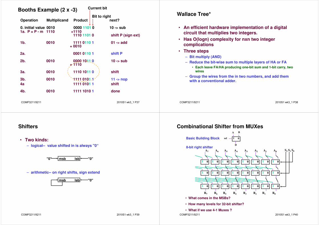
Shifters
• Two kinds:
– logical-- value shifted in is always "0“
– arithmetic-- on right shifts, sign extend
msb lsb"0" "0"
msb lsb "0"
COMP3211/9211 2010S1 wk3_1 P40
Combinational Shifter from MUXes
• What comes in the MSBs?
• How many levels for 32-bit shifter?
• What if we use 4-1 Muxes ?
1 0sel
A B
D
Basic Building Block
8-bit right shifter
1 0 1 0 1 0 1 0 1 0 1 0 1 0 1 0
1 0 1 0 1 0 1 0 1 0 1 0 1 0 1 0
1 0 1 0 1 0 1 0 1 0 1 0 1 0 1 0
S2 S1 S0A0A1A2A3A4A5A6A7
R0R1R2R3R4R5R6R7

COMP3211/9211 2010S1 wk3_1 P41
Funnel Shifter*
• A funnel shifter can do all three types shifts
• Selects N-bit field R from 2N-bit input Y and X
– Shift by k bits (0 ≤ k < N)
• Example
– Right shift input A by k bits
Logical: Y=0, X=A, offset=k
Arithmetic?
Rotate?
Left shifts?
XY
R
Shift Right
Shift Right
32 32
32
Y X
R
offsetoffset+N-1